fea project-tower analysis
TRANSCRIPT
ME/AE 408: Advanced Finite Element Analysis
Table of contents
• Project summary • Procedure • Numerical results and discussion • ABAQUS output Solid cross section – No mass Solid cross section – m1 Solid cross section – m2 Hollow cross section – No mass Hollow cross section – m1 Hollow cross section – m2
Project summary:
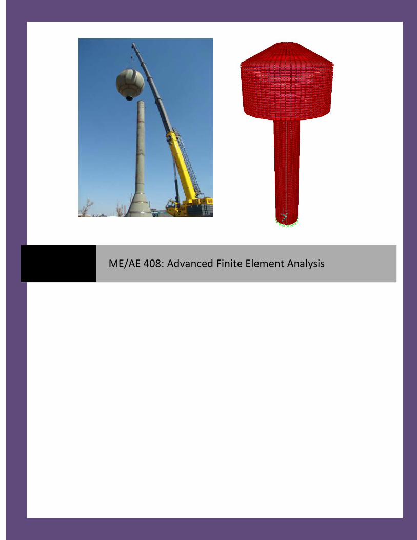
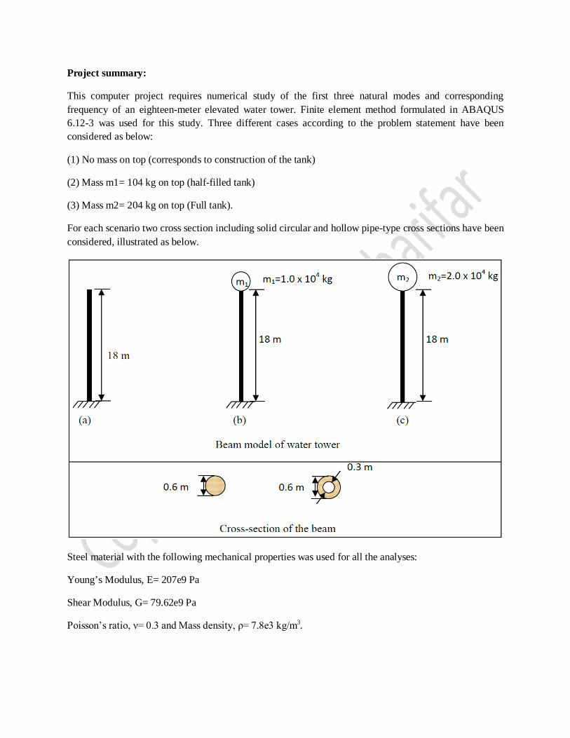
This computer project requires numerical study of the first three natural modes and corresponding frequency of an eighteen-meter elevated water tower. Finite element method formulated in ABAQUS 6.12-3 was used for this study. Three different cases according to the problem statement have been considered as below:
(1) No mass on top (corresponds to construction of the tank)
(2) Mass m1= 104 kg on top (half-filled tank)
(3) Mass m2= 204 kg on top (Full tank).
For each scenario two cross section including solid circular and hollow pipe-type cross sections have been considered, illustrated as below.
Steel material with the following mechanical properties was used for all the analyses:
Young’s Modulus, E= 207e9 Pa
Shear Modulus, G= 79.62e9 Pa
Poisson’s ratio, ν= 0.3 and Mass density, ρ= 7.8e3 kg/m3.
Procedure:
The commercially available finite element software package, ABAQUS was used for all the analyses in this project. The water tower was modelled as the cantilever beam, fixed at base for all the degrees of freedom and no constraint at the beam’s tip. According the project requirement, 100 elements were used to constitute the whole length of the cantilever beam.
Three different cases for analyses we considered, as (1) No mass on top (corresponds to construction of the tank), (2) Mass m1= 104 kg on top (half-filled tank) and (3) Mass m2= 204 kg on top (Full tank). All of these cases were analyzed considering two different cross sections configuration including: (a) A 0.6-meter diameter solid circular cross section and (b) a hollow pipe type circular cross section with an outside diameter of 0.6 meter and inside diameter of 0.3 meter.
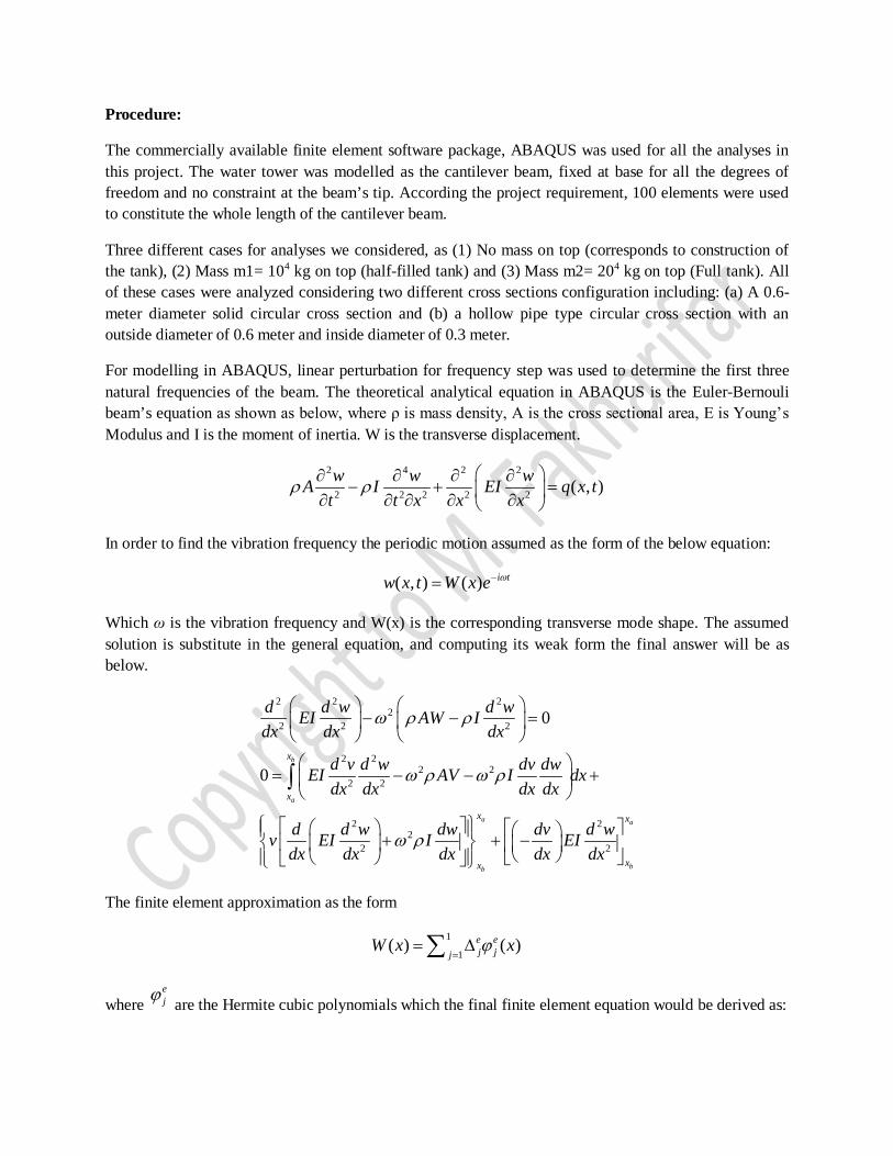
For modelling in ABAQUS, linear perturbation for frequency step was used to determine the first three natural frequencies of the beam. The theoretical analytical equation in ABAQUS is the Euler-Bernouli beam’s equation as shown as below, where ρ is mass density, A is the cross sectional area, E is Young’s Modulus and I is the moment of inertia. W is the transverse displacement.
2 4 2 2
2 2 2 2 2 ( , )w w wA I EI q x tt t x x x
ρ ρ ∂ ∂ ∂ ∂
− + = ∂ ∂ ∂ ∂ ∂
In order to find the vibration frequency the periodic motion assumed as the form of the below equation:
( , ) ( ) i tw x t W x e ω−=
Which ω is the vibration frequency and W(x) is the corresponding transverse mode shape. The assumed solution is substitute in the general equation, and computing its weak form the final answer will be as below.
2 2 22
2 2 2
2 22 2
2 2
2 22
2 2
0
0b
a
a a
bb
x
x
x x
xx
d d w d wEI AW Idx dx dx
d v d w dv dwEI AV I dxdx dx dx dx
d d w dw dv d wv EI I EIdx dx dx dx dx
ω ρ ρ
ω ρ ω ρ
ω ρ
− − =
= − − +
+ + −
∫
The finite element approximation as the form
1
1( ) ( )e e
j jjW x xϕ
== ∆∑
where ejϕ are the Hermite cubic polynomials which the final finite element equation would be derived as:
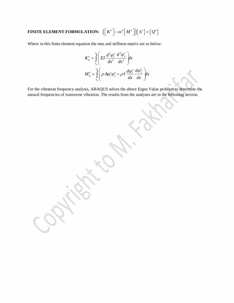
FINITE ELEMENT FORMULATION: ( ){ } { }2e e e eK M Qω − ∆ =
Where in this finite element equation the mas and stiffness matrix are as below:
22
2 2
b
a
b
a
x eeje i
ijx
x eeje e e i
ij i jx
ddK EI dxdx dx
ddM A I dxdx dx
ϕϕ
ϕϕρ ϕ ϕ ρ
=
= +
∫
∫
For the vibration frequency analysis, ABAQUS solves the above Eigen Value problem to determine the natural frequencies of transverse vibration. The results from the analyses are in the following section.
Results and discussion:
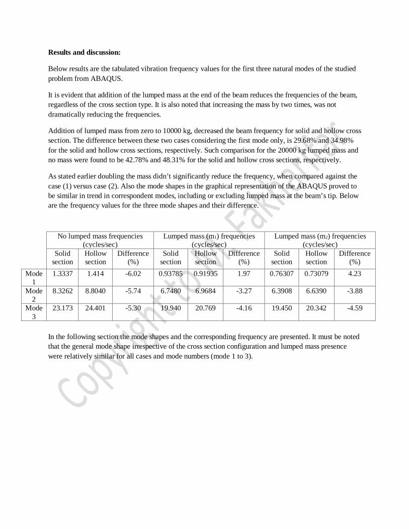
Below results are the tabulated vibration frequency values for the first three natural modes of the studied problem from ABAQUS.
It is evident that addition of the lumped mass at the end of the beam reduces the frequencies of the beam, regardless of the cross section type. It is also noted that increasing the mass by two times, was not dramatically reducing the frequencies.
Addition of lumped mass from zero to 10000 kg, decreased the beam frequency for solid and hollow cross section. The difference between these two cases considering the first mode only, is 29.68% and 34.98% for the solid and hollow cross sections, respectively. Such comparison for the 20000 kg lumped mass and no mass were found to be 42.78% and 48.31% for the solid and hollow cross sections, respectively.
As stated earlier doubling the mass didn’t significantly reduce the frequency, when compared against the case (1) versus case (2). Also the mode shapes in the graphical representation of the ABAQUS proved to be similar in trend in correspondent modes, including or excluding lumped mass at the beam’s tip. Below are the frequency values for the three mode shapes and their difference.
In the following section the mode shapes and the corresponding frequency are presented. It must be noted that the general mode shape irrespective of the cross section configuration and lumped mass presence were relatively similar for all cases and mode numbers (mode 1 to 3).
No lumped mass frequencies (cycles/sec)
Lumped mass (m1) frequencies (cycles/sec)
Lumped mass (m2) frequencies (cycles/sec)
Solid section
Hollow section
Difference (%)
Solid section
Hollow section
Difference (%)
Solid section
Hollow section
Difference (%)
Mode 1
1.3337 1.414 -6.02 0.93785 0.91935 1.97 0.76307 0.73079 4.23
Mode 2
8.3262 8.8040 -5.74 6.7480 6.9684 -3.27 6.3908 6.6390 -3.88
Mode 3
23.173 24.401 -5.30 19.940 20.769 -4.16 19.450 20.342 -4.59
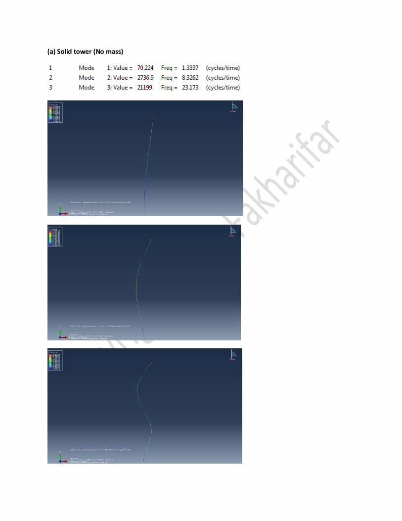
(a) Solid tower (No mass)
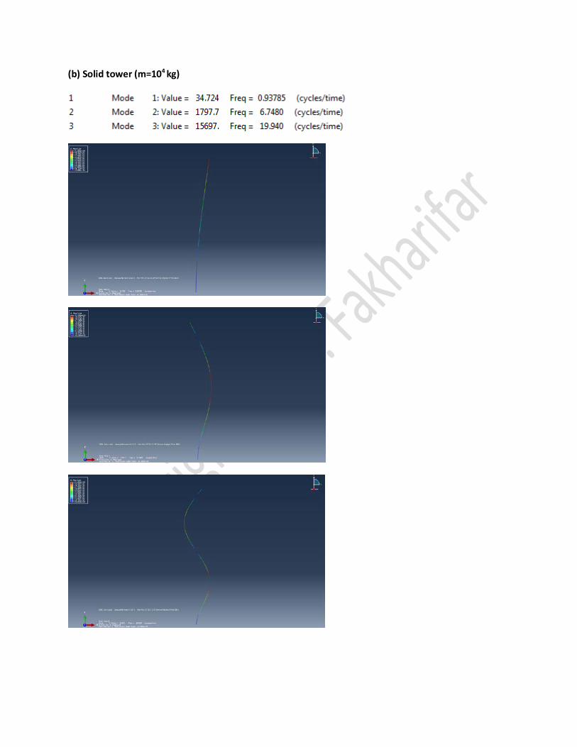
(b) Solid tower (m=104 kg)
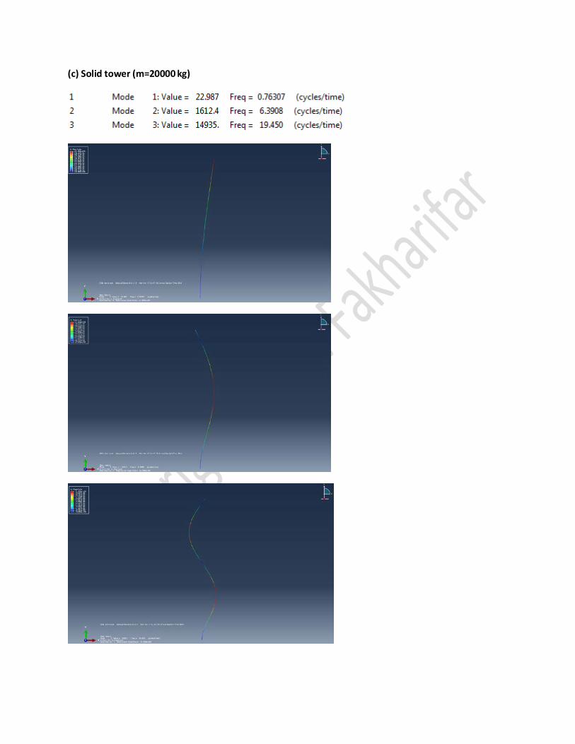
(c) Solid tower (m=20000 kg)
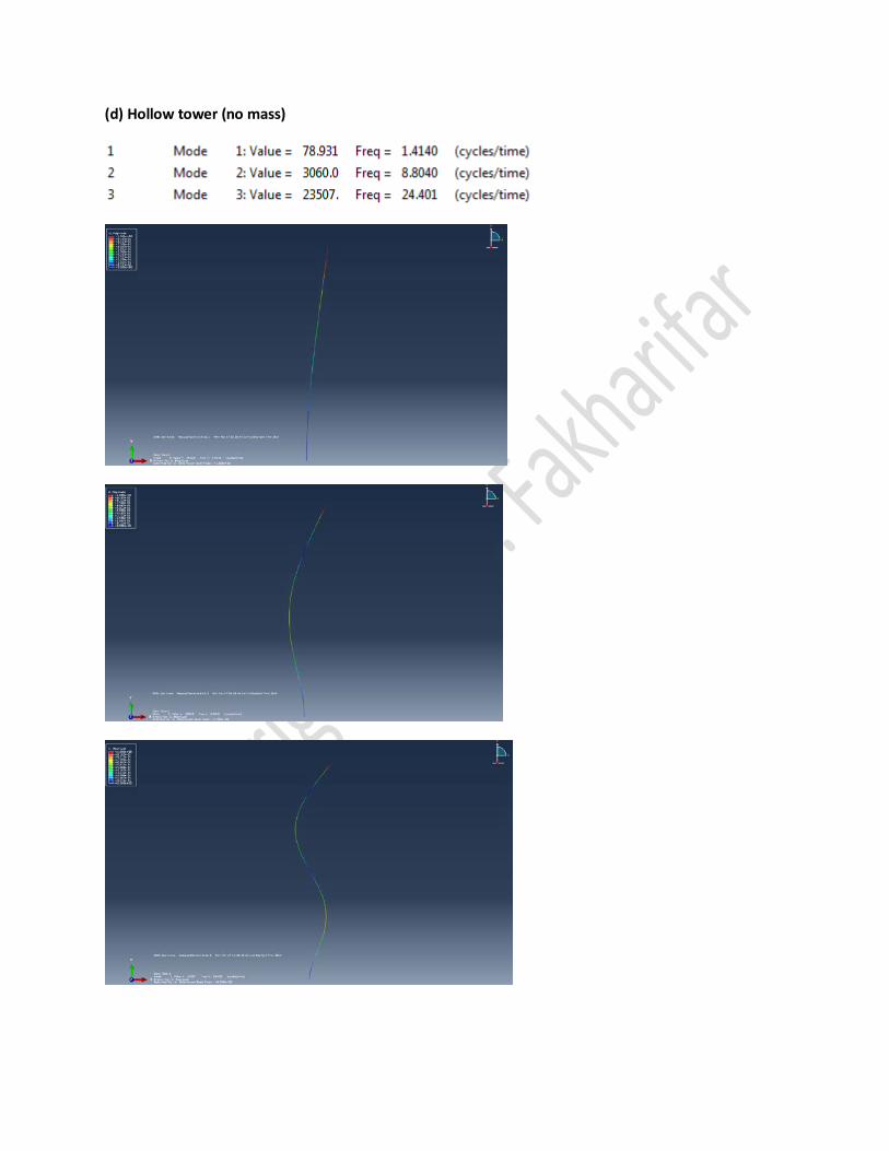
(d) Hollow tower (no mass)
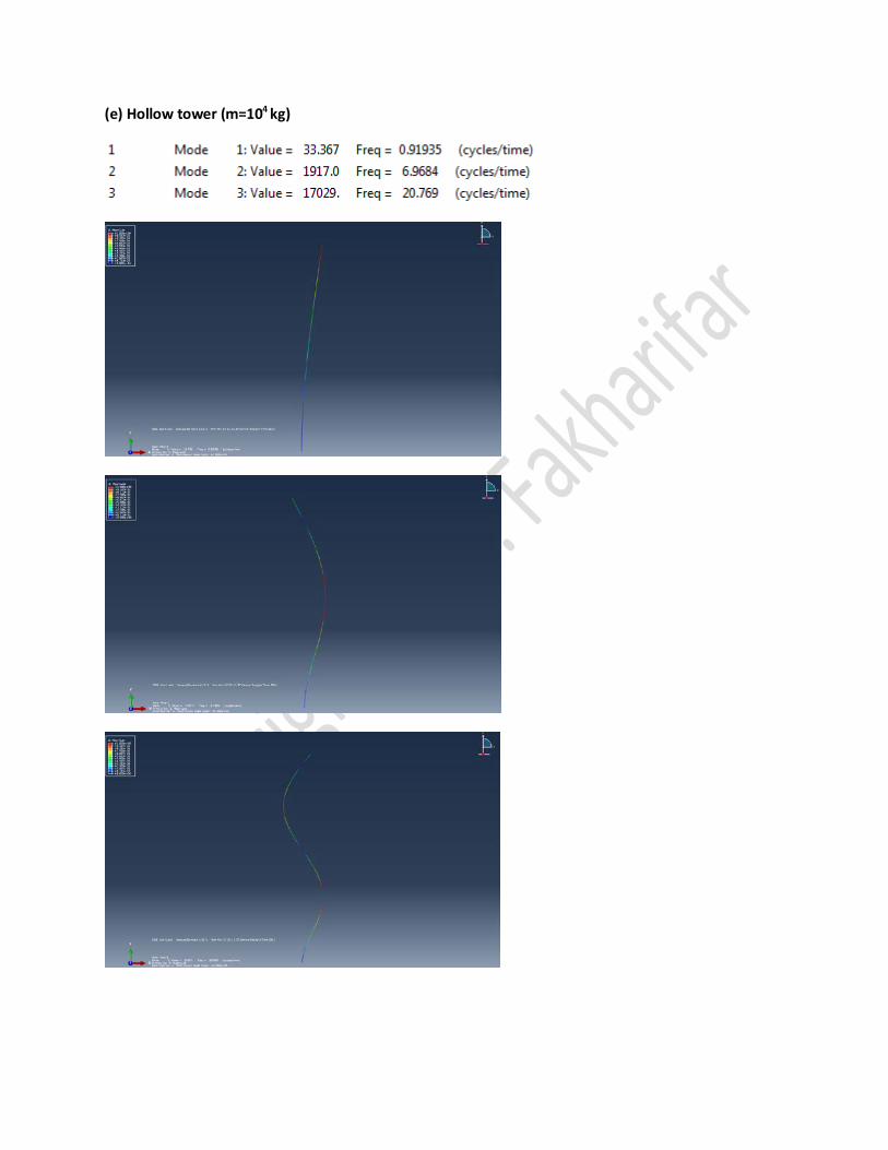
(e) Hollow tower (m=104 kg)
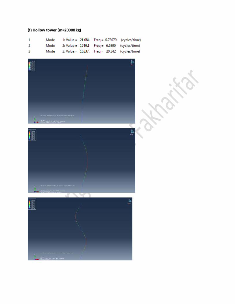
(f) Hollow tower (m=20000 kg)