fatigue of ti-6al-4v · fatigue notch factor, notch sensitivity and effect of ultimate strength and...
TRANSCRIPT
Chapter 3
© 2012 Hosseini, licensee InTech. This is an open access chapter distributed under the terms of the Creative Commons Attribution License (http://creativecommons.org/licenses/by/3.0), which permits unrestricted use, distribution, and reproduction in any medium, provided the original work is properly cited.
Fatigue of Ti-6Al-4V
Shabnam Hosseini
Additional information is available at the end of the chapter
http://dx.doi.org/10.5772/45753
1. Introduction
Metallic biomaterials have essentially three fields of use; these are the artificial hip joints, screw, plates and nails for internal fixation of fractures, and dental implants. Any of these devices must support high mechanical load and resistance of material against breakage is essential. High mechanical properties are needed for structural efficiency of surgical and dental implants. But their volume is restricted by anatomic realities what require good yield and fatigue strengths of metal [1].
The use of titanium alloys is due to their excellent corrosion resistance. Also, that is because of their tensile strength, a high strength to weight ratio and low elastic modulus. Titanium continues to be widely used in biomedical applications. Ti-6Al-4V alloy is the most frequently used these days [2].
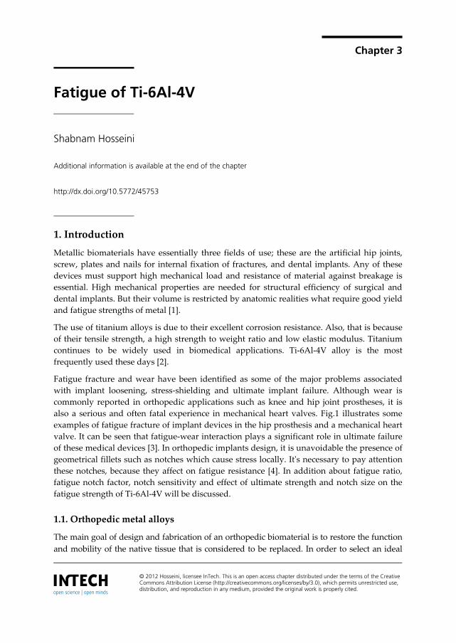
Fatigue fracture and wear have been identified as some of the major problems associated with implant loosening, stress-shielding and ultimate implant failure. Although wear is commonly reported in orthopedic applications such as knee and hip joint prostheses, it is also a serious and often fatal experience in mechanical heart valves. Fig.1 illustrates some examples of fatigue fracture of implant devices in the hip prosthesis and a mechanical heart valve. It can be seen that fatigue-wear interaction plays a significant role in ultimate failure of these medical devices [3]. In orthopedic implants design, it is unavoidable the presence of geometrical fillets such as notches which cause stress locally. It's necessary to pay attention these notches, because they affect on fatigue resistance [4]. In addition about fatigue ratio, fatigue notch factor, notch sensitivity and effect of ultimate strength and notch size on the fatigue strength of Ti-6Al-4V will be discussed.
1.1. Orthopedic metal alloys
The main goal of design and fabrication of an orthopedic biomaterial is to restore the function and mobility of the native tissue that is considered to be replaced. In order to select an ideal
Biomedical Engineering – Technical Applications in Medicine 76
biomaterial for orthopedic and dental applications specific property requirements must be fulfilled. The ideal materials for hard tissue replacement should be biocompatible and bioadhesive, possess adequate mechanical properties to tolerate the applied physiological load, be corrosion/wear resistant and finally show good bioactivity to ensure sufficient bonding at the material/bone interface. The materials used in orthopedic surgery can be divided into five major classes of metals, polymers, ceramics, composites, and natural materials [5].
Figure 1. Some examples of fatigue failure of medical devices: (a) hip prosthesis; (b) explanted Bjo¨rk–Shiley polyacetal disc mechanical heart valve(arrow indicates fatigue-wear mark)[1].
Compared to other biomaterials like ceramics and polymers, the metallic biomaterials offer a wider range of mechanical properties such as high strength, ductility, fracture toughness, hardness, formability, as well as corrosion resistance, and biocompatibility. These are the required properties for most load-bearing applications in fracture fixation and bone replacement (total joint arthroplasty) [5].
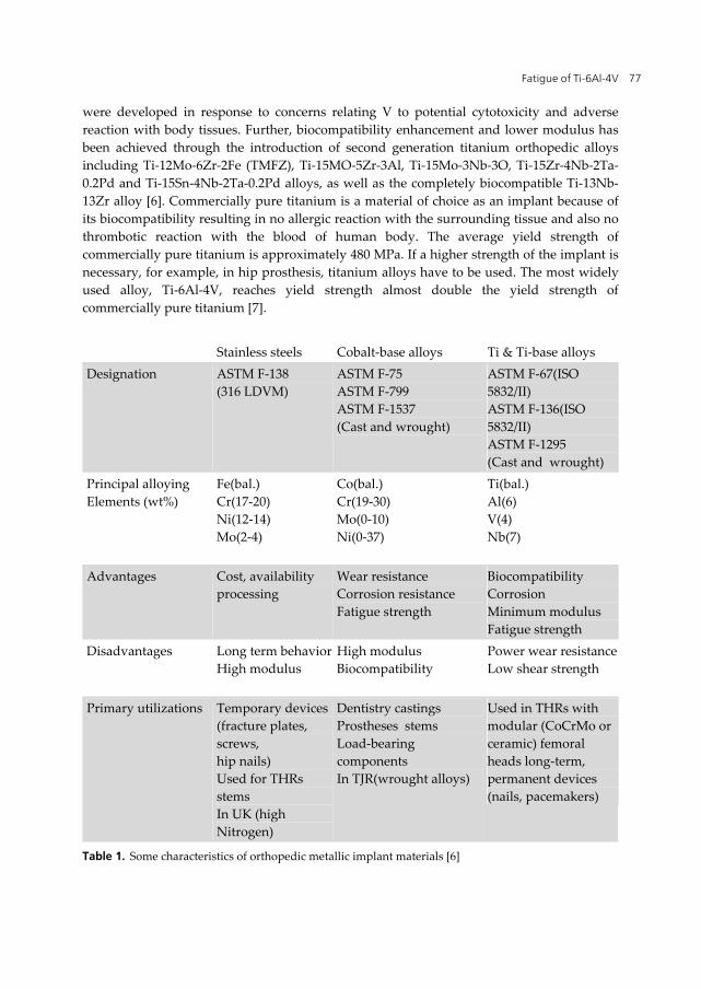
Standard metallic orthopedic materials include stainless steels, cobalt-base alloys, and titanium base alloys (table 1), with an increasing number of devices being made of titanium and titanium alloys. The latter alloys are generally preferred to stainless steel and Co-alloys because of their lower modulus, superior biocompatibility and corrosion resistance [6].
1.2. Titanium and its alloy as orthopedic biomaterials
The need to find more reliable materials to replace broken or deteriorating parts of the human body is increasing with the increase in number of both younger and older recipients. Modern surgery and dentistry need metals and alloys of extreme chemical inertness and adequate mechanical strength. Metals and alloys in use include stainless steel, Co-Ni-Cr alloy, cast and wrought Co-Cr-Mo alloy, commercially pure titanium, Ti-6Al-4V alloy and other titanium alloys [7]. Recently, new titanium alloy compositions, specifically tailored for biomedical applications, have been developed. These first generation orthopedic alloys included Ti-6Al-7Nb and Ti-5Al-2.5Fe. Two alloys with properties similar to Ti-6Al-4V that
Fatigue of Ti-6Al-4V 77
were developed in response to concerns relating V to potential cytotoxicity and adverse reaction with body tissues. Further, biocompatibility enhancement and lower modulus has been achieved through the introduction of second generation titanium orthopedic alloys including Ti-12Mo-6Zr-2Fe (TMFZ), Ti-15MO-5Zr-3Al, Ti-15Mo-3Nb-3O, Ti-15Zr-4Nb-2Ta-0.2Pd and Ti-15Sn-4Nb-2Ta-0.2Pd alloys, as well as the completely biocompatible Ti-13Nb-13Zr alloy [6]. Commercially pure titanium is a material of choice as an implant because of its biocompatibility resulting in no allergic reaction with the surrounding tissue and also no thrombotic reaction with the blood of human body. The average yield strength of commercially pure titanium is approximately 480 MPa. If a higher strength of the implant is necessary, for example, in hip prosthesis, titanium alloys have to be used. The most widely used alloy, Ti-6Al-4V, reaches yield strength almost double the yield strength of commercially pure titanium [7].
Stainless steels Cobalt-base alloys Ti & Ti-base alloys Designation ASTM F-138
(316 LDVM) ASTM F-75 ASTM F-799 ASTM F-1537 (Cast and wrought)
ASTM F-67(ISO 5832/II) ASTM F-136(ISO 5832/II) ASTM F-1295 (Cast and wrought)
Principal alloying Elements (wt%)
Fe(bal.) Cr(17-20) Ni(12-14) Mo(2-4)
Co(bal.) Cr(19-30) Mo(0-10) Ni(0-37)
Ti(bal.) Al(6) V(4) Nb(7)
Advantages Cost, availability processing
Wear resistance Corrosion resistance Fatigue strength
Biocompatibility Corrosion Minimum modulus Fatigue strength
Disadvantages Long term behaviorHigh modulus
High modulus Biocompatibility
Power wear resistance Low shear strength
Primary utilizations Temporary devices(fracture plates, screws, hip nails) Used for THRs stems In UK (high Nitrogen)
Dentistry castings Prostheses stems Load-bearing components In TJR(wrought alloys)
Used in THRs with modular (CoCrMo or ceramic) femoral heads long-term, permanent devices (nails, pacemakers)
Table 1. Some characteristics of orthopedic metallic implant materials [6]
Biomedical Engineering – Technical Applications in Medicine 78
Titanium is a transition metal with an incomplete shell in its electronic structure enables it to form solid solution with most substitutional elements having a size factor within ±20%. In its elemental form titanium has a high melting point (1678˚C), exhibiting a hexagonal close packed crystal structure (hcp) α up to the beta (882.5˚C), transforming to a body centered cubic structure(bcc) β above this temperature.
Titanium alloys may be classified as either α, near-α, α+β, metastable β or stable β depending upon their room temperature microstructure. IN this regard alloying elements for titanium fall into three categories: α-stabilizers, such as Al, O, N, C, β-stabilizer such as Mo, V, Nb, Ta, Fe, W, Cr, Si, Ni, Co, Mn, H and neutral, such as Zr. Α and near-α titanium alloys exhibit superior corrosion resistance with their utility as biomedical materials being principally limited by their low ambient temperature strength. In contrast, α+β alloys exhibit higher strength due to the presence of both α and β phases. Their properties depend upon composition, the relative proportions of the α/β phases, and the alloy’s prior thermal treatment and thermo-mechanical processing conditions. β alloys(metastable or stable) are titanium alloys with high strength, good formability and high hardenability. β alloys also offer the unique possibility of combined low elastic modulus and superior corrosion resistance[8].
Ti alloys were first used in orthopedics in the mid-1940s and have continued to gain attention because of their unique properties, including high specific strength, light weight, excellent corrosion resistance and biocompatibility. Due to the aforementioned properties, this class of materials exhibits tremendous clinical advantages in terms of reduced recovery time and rehabilitation, and improved comfort for patients. However, for bone replacement components, the strength of pure Ti is not sufficient and Ti alloys are preferred due to their superior mechanical properties. In general, alloying elements would lead to an improvement in the properties of Ti for orthopedic applications. Ti-6Al-4V ELI and NiTi shape memory alloys (SMA) are the most commonly used Ti alloys in orthopedic applications because of their good combination of mechanical properties and corrosion resistance. However, the possible release of toxic ions from aluminum (Al), vanadium (V) and nickel (Ni) during in vivo corrosion of the implant remains the matter of concern. Al for exceeding content of 7% at low temperature would lead to possible embrittlement and it may also cause severe neurological, e.g. Alzheimer’s disease and metabolic bone diseases, e.g. osteomalacia. Similarly, V can alter the kinetics of the enzyme activity associated with the cells and results in potential cytotoxic effects and adverse tissue reactions. Moreover, the oxide layer of Al2O3 and VO2 are less thermodynamically stable than that of TiO2, as their harmful debris may take place in living organism. Evident cytotoxic and allergic responses of Ni have also been reported. Thus, it is necessary to develop new Ti alloys that contain non-toxic elements [5]. New titanium alloys are being introduced to change the chemical composition and the mechanical properties. Some titanium alloys that are in use today or are being considered for use as implant materials are listed in table 1 along with their mechanical properties. The properties in table 2 result from specific heat treatments and will vary depending on their processing parameters. Information in this table permits a comparison of mechanical properties of pure titanium, some alpha/beta titanium alloys and some beta titanium alloys [7].
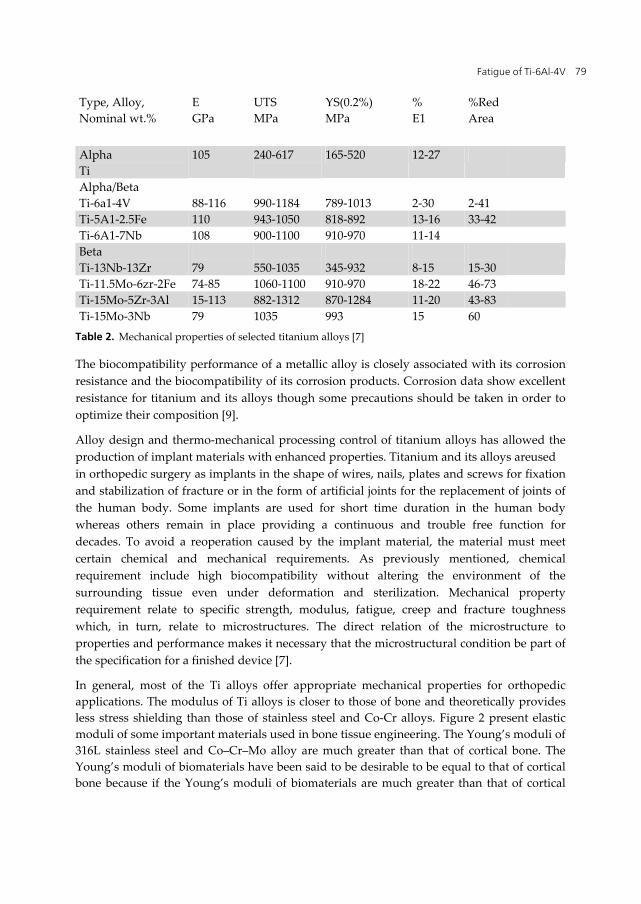
Fatigue of Ti-6Al-4V 79
Type, Alloy, Nominal wt.%
E GPa
UTS MPa
YS(0.2%) MPa
% E1
%Red Area
Alpha Ti
105 240-617
165-520 12-27
Alpha/Beta Ti-6a1-4V
88-116
990-1184
789-1013
2-30
2-41
Ti-5A1-2.5Fe 110 943-1050 818-892 13-16 33-42 Ti-6A1-7Nb 108 900-1100 910-970 11-14 Beta Ti-13Nb-13Zr
79
550-1035
345-932
8-15
15-30
Ti-11.5Mo-6zr-2Fe 74-85 1060-1100 910-970 18-22 46-73 Ti-15Mo-5Zr-3Al 15-113 882-1312 870-1284 11-20 43-83 Ti-15Mo-3Nb 79 1035 993 15 60
Table 2. Mechanical properties of selected titanium alloys [7]
The biocompatibility performance of a metallic alloy is closely associated with its corrosion resistance and the biocompatibility of its corrosion products. Corrosion data show excellent resistance for titanium and its alloys though some precautions should be taken in order to optimize their composition [9].
Alloy design and thermo-mechanical processing control of titanium alloys has allowed the production of implant materials with enhanced properties. Titanium and its alloys areused in orthopedic surgery as implants in the shape of wires, nails, plates and screws for fixation and stabilization of fracture or in the form of artificial joints for the replacement of joints of the human body. Some implants are used for short time duration in the human body whereas others remain in place providing a continuous and trouble free function for decades. To avoid a reoperation caused by the implant material, the material must meet certain chemical and mechanical requirements. As previously mentioned, chemical requirement include high biocompatibility without altering the environment of the surrounding tissue even under deformation and sterilization. Mechanical property requirement relate to specific strength, modulus, fatigue, creep and fracture toughness which, in turn, relate to microstructures. The direct relation of the microstructure to properties and performance makes it necessary that the microstructural condition be part of the specification for a finished device [7].
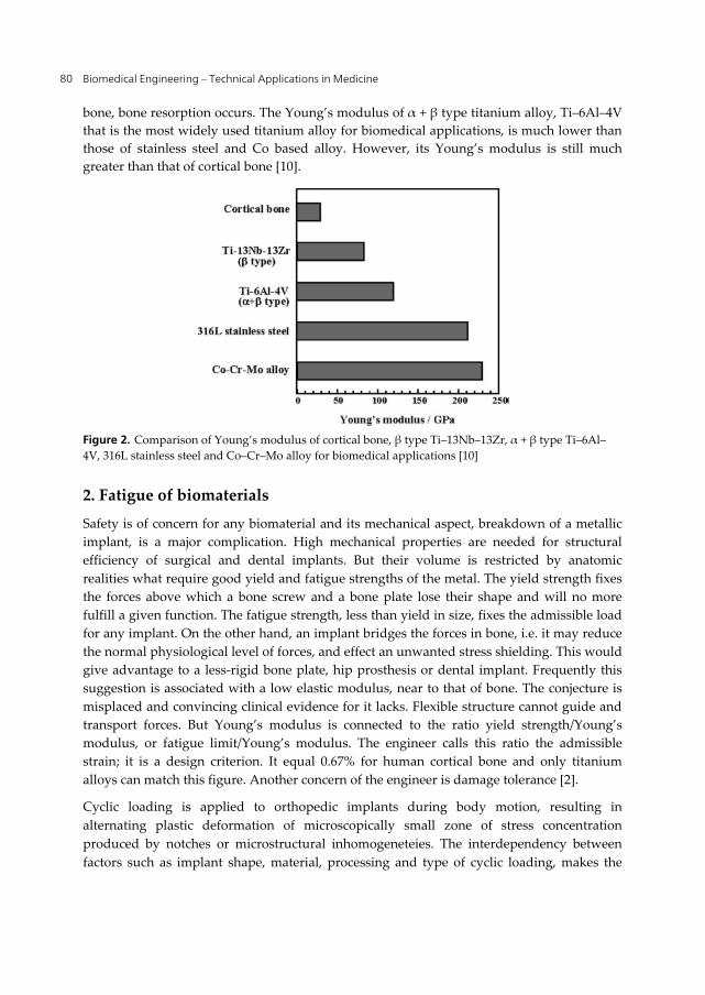
In general, most of the Ti alloys offer appropriate mechanical properties for orthopedic applications. The modulus of Ti alloys is closer to those of bone and theoretically provides less stress shielding than those of stainless steel and Co-Cr alloys. Figure 2 present elastic moduli of some important materials used in bone tissue engineering. The Young’s moduli of 316L stainless steel and Co–Cr–Mo alloy are much greater than that of cortical bone. The Young’s moduli of biomaterials have been said to be desirable to be equal to that of cortical bone because if the Young’s moduli of biomaterials are much greater than that of cortical
Biomedical Engineering – Technical Applications in Medicine 80
bone, bone resorption occurs. The Young’s modulus of α + β type titanium alloy, Ti–6Al–4V that is the most widely used titanium alloy for biomedical applications, is much lower than those of stainless steel and Co based alloy. However, its Young’s modulus is still much greater than that of cortical bone [10].
Figure 2. Comparison of Young’s modulus of cortical bone, β type Ti–13Nb–13Zr, α + β type Ti–6Al–4V, 316L stainless steel and Co–Cr–Mo alloy for biomedical applications [10]
2. Fatigue of biomaterials
Safety is of concern for any biomaterial and its mechanical aspect, breakdown of a metallic implant, is a major complication. High mechanical properties are needed for structural efficiency of surgical and dental implants. But their volume is restricted by anatomic realities what require good yield and fatigue strengths of the metal. The yield strength fixes the forces above which a bone screw and a bone plate lose their shape and will no more fulfill a given function. The fatigue strength, less than yield in size, fixes the admissible load for any implant. On the other hand, an implant bridges the forces in bone, i.e. it may reduce the normal physiological level of forces, and effect an unwanted stress shielding. This would give advantage to a less-rigid bone plate, hip prosthesis or dental implant. Frequently this suggestion is associated with a low elastic modulus, near to that of bone. The conjecture is misplaced and convincing clinical evidence for it lacks. Flexible structure cannot guide and transport forces. But Young’s modulus is connected to the ratio yield strength/Young’s modulus, or fatigue limit/Young’s modulus. The engineer calls this ratio the admissible strain; it is a design criterion. It equal 0.67% for human cortical bone and only titanium alloys can match this figure. Another concern of the engineer is damage tolerance [2].
Cyclic loading is applied to orthopedic implants during body motion, resulting in alternating plastic deformation of microscopically small zone of stress concentration produced by notches or microstructural inhomogeneteies. The interdependency between factors such as implant shape, material, processing and type of cyclic loading, makes the
Fatigue of Ti-6Al-4V 81
determination of the fatigue resistance of a component an intricate, but critical, task. Since testing an actual implant under simulated implantation and load conditions is a difficult and expensive process, standardized fatigue tests have been selected for initial screening of orthopedic material candidates, joint simulator trials being generally reserved for a later stage in the implant development process. Standard fatigue tests include tension/compression, bending, torsion, and rotating bending fatigue (RBF) testing, the latter, a relatively simple test, being widely used to evaluate orthopedic metallic materials. Unfortunately, no standard for fatigue evaluation of biomaterials testing has yet been established, a variety of testing conditions being encountered in reported fatigue studies of orthopedic materials [6].
One of the main reasons for concern about fatigue of biomaterials arises from the adverse host-tissue response to wear debris generated by the fatigue process. This appears to be a natural defence mechanism of the body. The wear debris often invokes an inflammatory and immunological response. This in turn causes blood clotting processes, leukocytes, macrophages and, for severe cases, giant cells to move in on the foreign wear particles resulting in interfacial problems between the implant and the host tissue. Numerous biochemical activities occur at this stage. These include a change in the local environment to a highly acidic one (pH less than 3) [1].
Metal fatigue has been extensively studied [1,2,11]. The fatigue strengths of common metallic implant alloys used in hip replacements such as stainless steel, cobalt chrome and titanium, and their relationship to their microstructures, surface and corrosion properties have been reported [1].
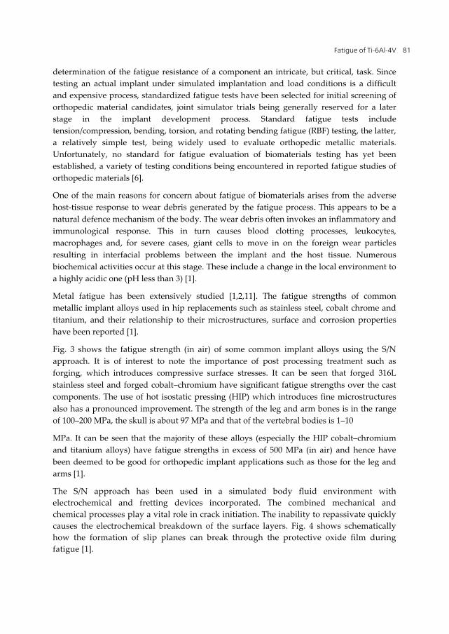
Fig. 3 shows the fatigue strength (in air) of some common implant alloys using the S/N approach. It is of interest to note the importance of post processing treatment such as forging, which introduces compressive surface stresses. It can be seen that forged 316L stainless steel and forged cobalt–chromium have significant fatigue strengths over the cast components. The use of hot isostatic pressing (HIP) which introduces fine microstructures also has a pronounced improvement. The strength of the leg and arm bones is in the range of 100–200 MPa, the skull is about 97 MPa and that of the vertebral bodies is 1–10
MPa. It can be seen that the majority of these alloys (especially the HIP cobalt–chromium and titanium alloys) have fatigue strengths in excess of 500 MPa (in air) and hence have been deemed to be good for orthopedic implant applications such as those for the leg and arms [1].
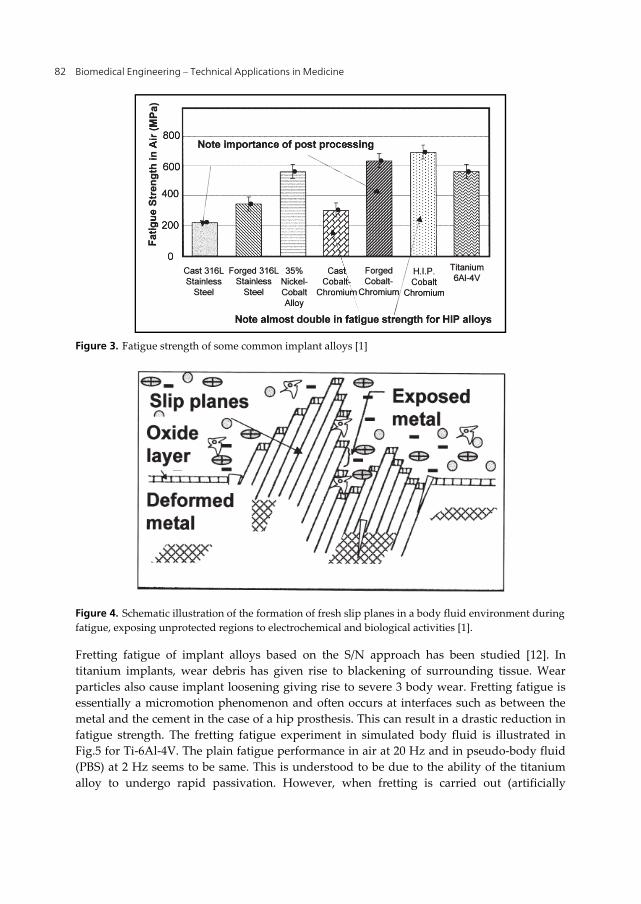
The S/N approach has been used in a simulated body fluid environment with electrochemical and fretting devices incorporated. The combined mechanical and chemical processes play a vital role in crack initiation. The inability to repassivate quickly causes the electrochemical breakdown of the surface layers. Fig. 4 shows schematically how the formation of slip planes can break through the protective oxide film during fatigue [1].
Biomedical Engineering – Technical Applications in Medicine 82
Figure 3. Fatigue strength of some common implant alloys [1]
Figure 4. Schematic illustration of the formation of fresh slip planes in a body fluid environment during fatigue, exposing unprotected regions to electrochemical and biological activities [1].
Fretting fatigue of implant alloys based on the S/N approach has been studied [12]. In titanium implants, wear debris has given rise to blackening of surrounding tissue. Wear particles also cause implant loosening giving rise to severe 3 body wear. Fretting fatigue is essentially a micromotion phenomenon and often occurs at interfaces such as between the metal and the cement in the case of a hip prosthesis. This can result in a drastic reduction in fatigue strength. The fretting fatigue experiment in simulated body fluid is illustrated in Fig.5 for Ti-6Al-4V. The plain fatigue performance in air at 20 Hz and in pseudo-body fluid (PBS) at 2 Hz seems to be same. This is understood to be due to the ability of the titanium alloy to undergo rapid passivation. However, when fretting is carried out (artificially
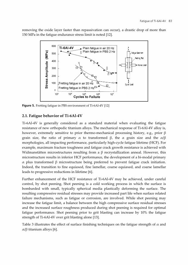
Fatigue of Ti-6Al-4V 83
removing the oxide layer faster than repassivation can occur), a drastic drop of more than 150 MPa in the fatigue endurance stress limit is noted [12].
Figure 5. Fretting fatigue in PBS environment of Ti-6Al-4V [12]
2.1. Fatigue behavior of Ti-6Al-4V
Ti-6Al-4V is generally considered as a standard material when evaluating the fatigue resistance of new orthopedic titanium alloys. The mechanical response of Ti-6Al-4V alloy is, however, extremely sensitive to prior thermo-mechanical processing history, e.g., prior β grain size, the ratio of primary α to transformed β, the α grain size and the α/β morphologies, all impacting performance, particularly high-cycle fatigue lifetime (HCF). For example, maximum fracture toughness and fatigue crack growth resistance is achieved with Widmanstätten microstructures resulting from a β recrystallization anneal. However, this microstructure results in inferior HCF performance, the development of a bi-modal primary α plus transformed β microstructure being preferred to prevent fatigue crack initiation. Indeed, the transition to fine equiaxed, fine lamellar, coarse equiaxed, and coarse lamellar leads to progressive reductions in lifetime [6].
Further enhancement of the HCF resistance of Ti-6Al-4V may be achieved, under careful control, by shot peening. Shot peening is a cold working process in which the surface is bombarded with small, typically spherical media plastically deforming the surface. The resulting compressive residual stresses may provide increased part life when surface related failure mechanisms, such as fatigue or corrosion, are involved. While shot peening may increase the fatigue limit, a balance between the high compressive surface residual stresses and the increased surface roughness produced during shot peening is required for optimal fatigue performance. Shot peening prior to grit blasting can increase by 10% the fatigue strength of Ti-6Al-4V over grit blasting alone [13].
Table 3 illustrates the effect of surface finishing techniques on the fatigue strength of α and α/β titanium alloys [6].
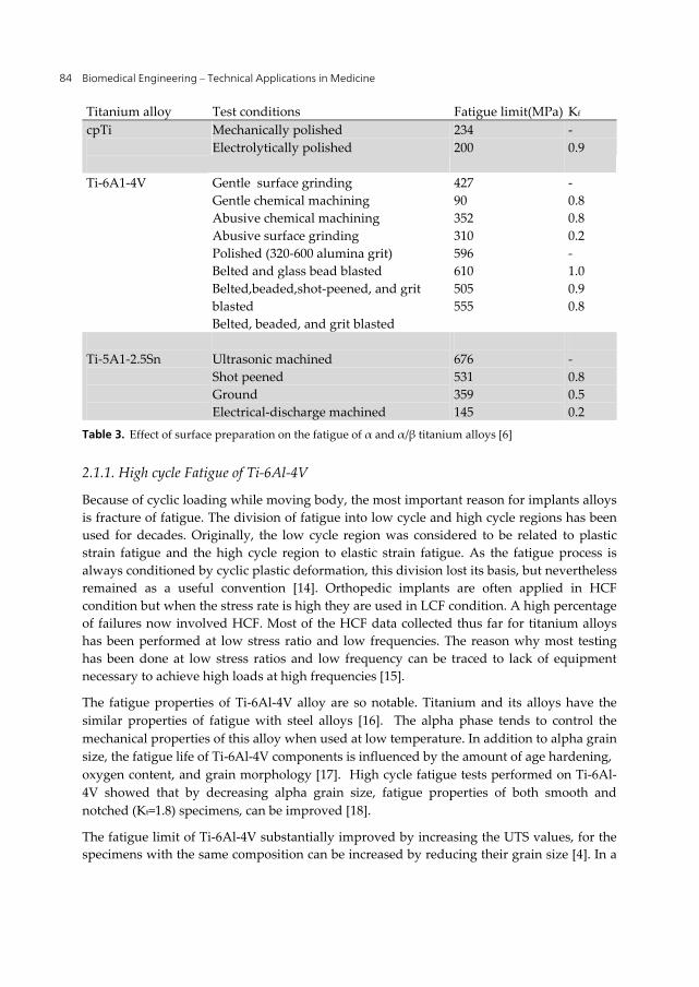
Biomedical Engineering – Technical Applications in Medicine 84
Titanium alloy Test conditions Fatigue limit(MPa) Kf cpTi
Mechanically polished Electrolytically polished
234 200
- 0.9
Ti-6A1-4V
Gentle surface grinding Gentle chemical machining Abusive chemical machining Abusive surface grinding Polished (320-600 alumina grit) Belted and glass bead blasted Belted,beaded,shot-peened, and grit blasted Belted, beaded, and grit blasted
427 90 352 310 596 610 505 555
- 0.8 0.8 0.2 - 1.0 0.9 0.8
Ti-5A1-2.5Sn
Ultrasonic machined Shot peened Ground Electrical-discharge machined
676 531 359 145
- 0.8 0.5 0.2
Table 3. Effect of surface preparation on the fatigue of α and α/β titanium alloys [6]
2.1.1. High cycle Fatigue of Ti-6Al-4V
Because of cyclic loading while moving body, the most important reason for implants alloys is fracture of fatigue. The division of fatigue into low cycle and high cycle regions has been used for decades. Originally, the low cycle region was considered to be related to plastic strain fatigue and the high cycle region to elastic strain fatigue. As the fatigue process is always conditioned by cyclic plastic deformation, this division lost its basis, but nevertheless remained as a useful convention [14]. Orthopedic implants are often applied in HCF condition but when the stress rate is high they are used in LCF condition. A high percentage of failures now involved HCF. Most of the HCF data collected thus far for titanium alloys has been performed at low stress ratio and low frequencies. The reason why most testing has been done at low stress ratios and low frequency can be traced to lack of equipment necessary to achieve high loads at high frequencies [15].
The fatigue properties of Ti-6Al-4V alloy are so notable. Titanium and its alloys have the similar properties of fatigue with steel alloys [16]. The alpha phase tends to control the mechanical properties of this alloy when used at low temperature. In addition to alpha grain size, the fatigue life of Ti-6Al-4V components is influenced by the amount of age hardening, oxygen content, and grain morphology [17]. High cycle fatigue tests performed on Ti-6Al-4V showed that by decreasing alpha grain size, fatigue properties of both smooth and notched (Kt=1.8) specimens, can be improved [18].
The fatigue limit of Ti-6Al-4V substantially improved by increasing the UTS values, for the specimens with the same composition can be increased by reducing their grain size [4]. In a
Fatigue of Ti-6Al-4V 85
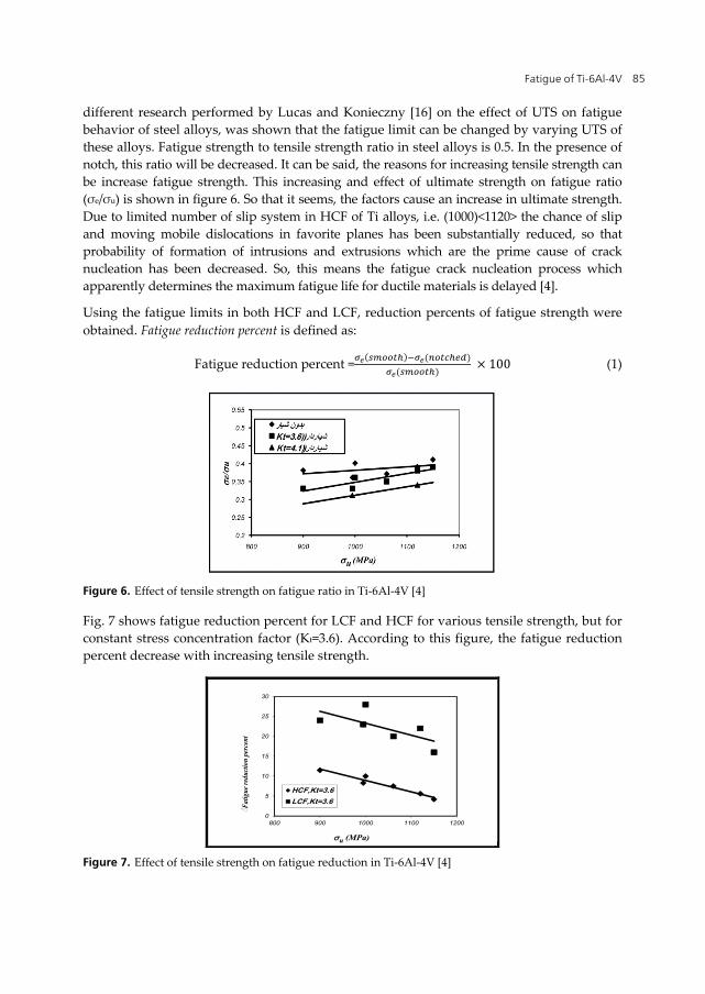
different research performed by Lucas and Konieczny [16] on the effect of UTS on fatigue behavior of steel alloys, was shown that the fatigue limit can be changed by varying UTS of these alloys. Fatigue strength to tensile strength ratio in steel alloys is 0.5. In the presence of notch, this ratio will be decreased. It can be said, the reasons for increasing tensile strength can be increase fatigue strength. This increasing and effect of ultimate strength on fatigue ratio (σe/σu) is shown in figure 6. So that it seems, the factors cause an increase in ultimate strength. Due to limited number of slip system in HCF of Ti alloys, i.e. (1000)<1120> the chance of slip and moving mobile dislocations in favorite planes has been substantially reduced, so that probability of formation of intrusions and extrusions which are the prime cause of crack nucleation has been decreased. So, this means the fatigue crack nucleation process which apparently determines the maximum fatigue life for ductile materials is delayed [4].
Using the fatigue limits in both HCF and LCF, reduction percents of fatigue strength were obtained. Fatigue reduction percent is defined as:
Fatigue reduction percent = ( ) ( )( ) × 100 (1)
Figure 6. Effect of tensile strength on fatigue ratio in Ti-6Al-4V [4]
Fig. 7 shows fatigue reduction percent for LCF and HCF for various tensile strength, but for constant stress concentration factor (Kt=3.6). According to this figure, the fatigue reduction percent decrease with increasing tensile strength.
900 11.5995 8.3
1000 101061 7.51120 5.61150 4.2900 24995 23
1000 281061 201120 221150 16
0
5
10
15
20
25
30
800 900 1000 1100 1200
◌Fat
igue
red
uctio
n pe
rcen
t
u (MPa)
HCF,Kt=3.6LCF,Kt=3.6
Figure 7. Effect of tensile strength on fatigue reduction in Ti-6Al-4V [4]
Biomedical Engineering – Technical Applications in Medicine 86
2.1.2. Fatigue notch factor and notch sensitivity
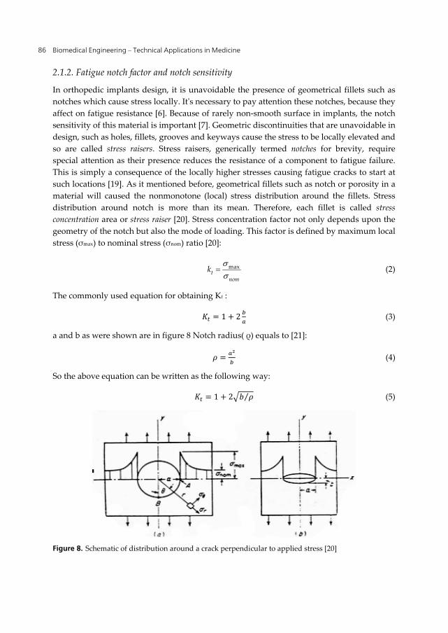
In orthopedic implants design, it is unavoidable the presence of geometrical fillets such as notches which cause stress locally. It's necessary to pay attention these notches, because they affect on fatigue resistance [6]. Because of rarely non-smooth surface in implants, the notch sensitivity of this material is important [7]. Geometric discontinuities that are unavoidable in design, such as holes, fillets, grooves and keyways cause the stress to be locally elevated and so are called stress raisers. Stress raisers, generically termed notches for brevity, require special attention as their presence reduces the resistance of a component to fatigue failure. This is simply a consequence of the locally higher stresses causing fatigue cracks to start at such locations [19]. As it mentioned before, geometrical fillets such as notch or porosity in a material will caused the nonmonotone (local) stress distribution around the fillets. Stress distribution around notch is more than its mean. Therefore, each fillet is called stress concentration area or stress raiser [20]. Stress concentration factor not only depends upon the geometry of the notch but also the mode of loading. This factor is defined by maximum local stress (σmax) to nominal stress (σnom) ratio [20]:
maxt
nomk (2)
The commonly used equation for obtaining Kt :
= 1 + 2 (3)
a and b as were shown are in figure 8 Notch radius( ρ) equals to [21]:
= (4)
So the above equation can be written as the following way:
= 1 + 2 ⁄ (5)
Figure 8. Schematic of distribution around a crack perpendicular to applied stress [20]
Fatigue of Ti-6Al-4V 87
The actual reduction factor at long fatigue lives, specifically at Nf =106 to 107 cycles or greater, is called the fatigue notch factor and is denoted Kf [19].
= (6)
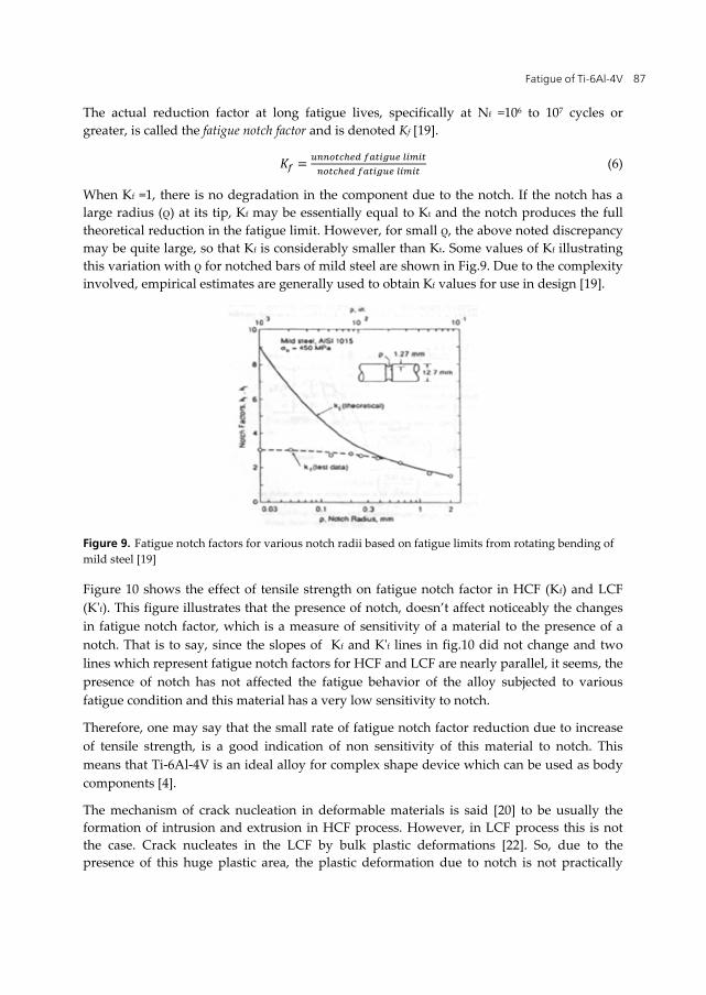
When Kf =1, there is no degradation in the component due to the notch. If the notch has a large radius (ρ) at its tip, Kf may be essentially equal to Kt and the notch produces the full theoretical reduction in the fatigue limit. However, for small ρ, the above noted discrepancy may be quite large, so that Kf is considerably smaller than Kt. Some values of Kf illustrating this variation with ρ for notched bars of mild steel are shown in Fig.9. Due to the complexity involved, empirical estimates are generally used to obtain Kf values for use in design [19].
Figure 9. Fatigue notch factors for various notch radii based on fatigue limits from rotating bending of mild steel [19]
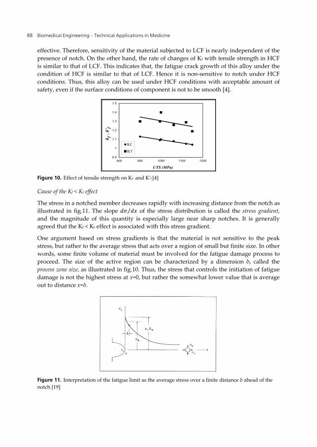
Figure 10 shows the effect of tensile strength on fatigue notch factor in HCF (Kf) and LCF (K'f). This figure illustrates that the presence of notch, doesn’t affect noticeably the changes in fatigue notch factor, which is a measure of sensitivity of a material to the presence of a notch. That is to say, since the slopes of Kf and K'f lines in fig.10 did not change and two lines which represent fatigue notch factors for HCF and LCF are nearly parallel, it seems, the presence of notch has not affected the fatigue behavior of the alloy subjected to various fatigue condition and this material has a very low sensitivity to notch.
Therefore, one may say that the small rate of fatigue notch factor reduction due to increase of tensile strength, is a good indication of non sensitivity of this material to notch. This means that Ti-6Al-4V is an ideal alloy for complex shape device which can be used as body components [4].
The mechanism of crack nucleation in deformable materials is said [20] to be usually the formation of intrusion and extrusion in HCF process. However, in LCF process this is not the case. Crack nucleates in the LCF by bulk plastic deformations [22]. So, due to the presence of this huge plastic area, the plastic deformation due to notch is not practically
Biomedical Engineering – Technical Applications in Medicine 88
effective. Therefore, sensitivity of the material subjected to LCF is nearly independent of the presence of notch. On the other hand, the rate of changes of Kf with tensile strength in HCF is similar to that of LCF. This indicates that, the fatigue crack growth of this alloy under the condition of HCF is similar to that of LCF. Hence it is non-sensitive to notch under HCF conditions. Thus, this alloy can be used under HCF conditions with acceptable amount of safety, even if the surface conditions of component is not to be smooth [4].
0.9
1
1.1
1.2
1.3
1.4
1.5
800 900 1000 1100 1200
Kf
, K' f
UTS (MPa)
Kf
K'f
Figure 10. Effect of tensile strength on Kf and K'f [4]
Cause of the Kf < Kt effect
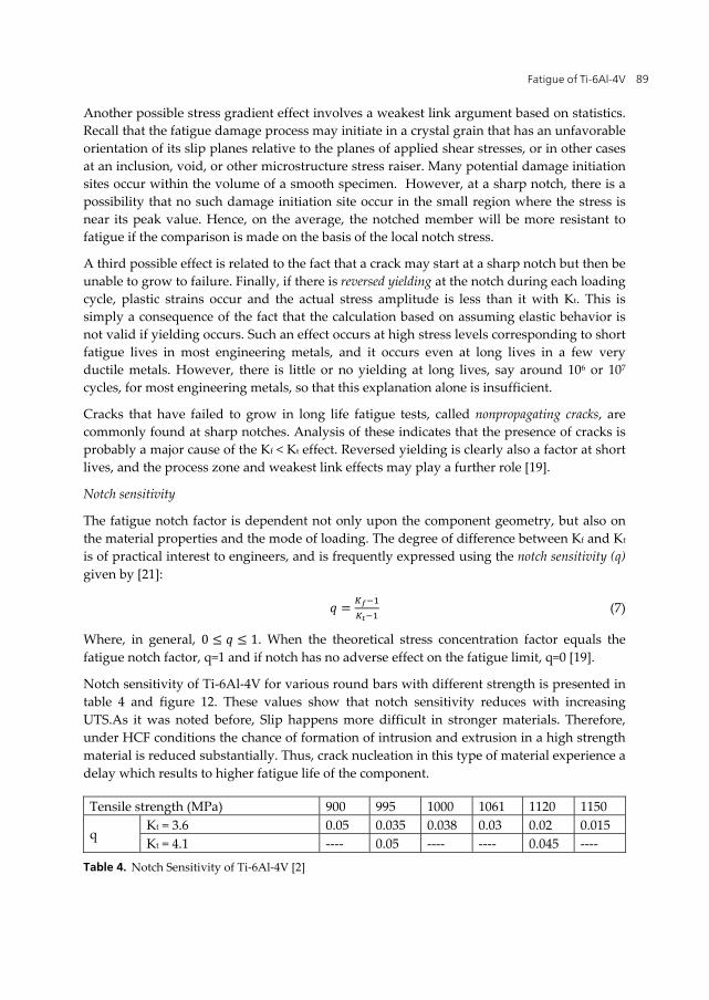
The stress in a notched member decreases rapidly with increasing distance from the notch as illustrated in fig.11. The slope ⁄ of the stress distribution is called the stress gradient, and the magnitude of this quantity is especially large near sharp notches. It is generally agreed that the Kf < Kt effect is associated with this stress gradient.
One argument based on stress gradients is that the material is not sensitive to the peak stress, but rather to the average stress that acts over a region of small but finite size. In other words, some finite volume of material must be involved for the fatigue damage process to proceed. The size of the active region can be characterized by a dimension δ, called the process zone size, as illustrated in fig.10. Thus, the stress that controls the initiation of fatigue damage is not the highest stress at x=0, but rather the somewhat lower value that is average out to distance x=δ.
Figure 11. Interpretation of the fatigue limit as the average stress over a finite distance δ ahead of the notch [19]
Fatigue of Ti-6Al-4V 89
Another possible stress gradient effect involves a weakest link argument based on statistics. Recall that the fatigue damage process may initiate in a crystal grain that has an unfavorable orientation of its slip planes relative to the planes of applied shear stresses, or in other cases at an inclusion, void, or other microstructure stress raiser. Many potential damage initiation sites occur within the volume of a smooth specimen. However, at a sharp notch, there is a possibility that no such damage initiation site occur in the small region where the stress is near its peak value. Hence, on the average, the notched member will be more resistant to fatigue if the comparison is made on the basis of the local notch stress.
A third possible effect is related to the fact that a crack may start at a sharp notch but then be unable to grow to failure. Finally, if there is reversed yielding at the notch during each loading cycle, plastic strains occur and the actual stress amplitude is less than it with Kt. This is simply a consequence of the fact that the calculation based on assuming elastic behavior is not valid if yielding occurs. Such an effect occurs at high stress levels corresponding to short fatigue lives in most engineering metals, and it occurs even at long lives in a few very ductile metals. However, there is little or no yielding at long lives, say around 106 or 107 cycles, for most engineering metals, so that this explanation alone is insufficient.
Cracks that have failed to grow in long life fatigue tests, called nonpropagating cracks, are commonly found at sharp notches. Analysis of these indicates that the presence of cracks is probably a major cause of the Kf < Kt effect. Reversed yielding is clearly also a factor at short lives, and the process zone and weakest link effects may play a further role [19].
Notch sensitivity
The fatigue notch factor is dependent not only upon the component geometry, but also on the material properties and the mode of loading. The degree of difference between Kf and Kt is of practical interest to engineers, and is frequently expressed using the notch sensitivity (q) given by [21]:
= (7)
Where, in general, 0 ≤ ≤ 1. When the theoretical stress concentration factor equals the fatigue notch factor, q=1 and if notch has no adverse effect on the fatigue limit, q=0 [19].
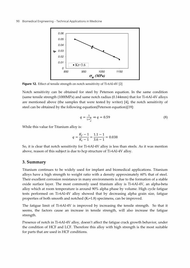
Notch sensitivity of Ti-6Al-4V for various round bars with different strength is presented in table 4 and figure 12. These values show that notch sensitivity reduces with increasing UTS.As it was noted before, Slip happens more difficult in stronger materials. Therefore, under HCF conditions the chance of formation of intrusion and extrusion in a high strength material is reduced substantially. Thus, crack nucleation in this type of material experience a delay which results to higher fatigue life of the component.
Tensile strength (MPa) 900 995 1000 1061 1120 1150
q Kt = 3.6 0.05 0.035 0.038 0.03 0.02 0.015 Kt = 4.1 ---- 0.05 ---- ---- 0.045 ----
Table 4. Notch Sensitivity of Ti-6Al-4V [2]
Biomedical Engineering – Technical Applications in Medicine 90
900 0.05995 0.035
1000 0.0381061 0.031120 0.021150 0.015
0
0.01
0.02
0.03
0.04
0.05
0.06
850 950 1050 1150
q
u (MPa)
Kt=3.6
Figure 12. Effect of tensile strength on notch sensitivity of Ti-6Al-4V [2]
Notch sensitivity can be obtained for steel by Peterson equation. In the same condition (same tensile strength (1000MPa) and same notch radius (0.144mm) that for Ti-6Al-4V alloys are mentioned above (the samples that were tested by writer) [4], the notch sensitivity of steel can be obtained by the following equation(Peterson equation)[19]:
= ⇒ = 0.59 (8)
While this value for Titanium alloy is:
= − 1− 1 = 1.1 − 13.6 − 1 = 0.038
So, it is clear that notch sensitivity for Ti-6Al-4V alloy is less than steels. As it was mention above, reason of this subject is due to hcp structure of Ti-6Al-4V alloy.
3. Summary
Titanium continues to be widely used for implant and biomedical applications. Titanium alloys have a high strength to weight ratio with a density approximately 60% that of steel. Their excellent corrosion resistance in many environments is due to the formation of a stable oxide surface layer. The most commonly used titanium alloy is Ti-6Al-4V, an alpha-beta alloy which at room temperature is around 90% alpha phase by volume. High cycle fatigue tests performed on Ti-6Al-4V alloy showed that by decreasing alpha grain size, fatigue properties of both smooth and notched (Kt=1.8) specimens, can be improved.
The fatigue limit of Ti-6Al-4V is improved by increasing the tensile strength. So that it seems, the factors cause an increase in tensile strength, will also increase the fatigue strength.
Presence of notch in Ti-6Al-4V alloy, doesn’t affect the fatigue crack growth behavior, under the condition of HCF and LCF. Therefore this alloy with high strength is the most suitable for parts that are used in HCF conditions.
Fatigue of Ti-6Al-4V 91
Notch sensitivity of Ti-6Al-4V alloy reduces with increasing tensile strength for a constant concentration factor (Kt), and this value is less than steel alloys in the same condition.
Author details
Shabnam Hosseini Department of Metallurgy, Ayatollah Amoli Branch, Islamic Azad University, Amol, Iran
4. References
[1] S.H.Teoh, “Fatigue of biomaterials: a revie”", International journal of fatigue, 22, 2000, 825-837.
[2] Shabnam Hosseini, M.B.Limooei,“Investigation of fatigue behavior and notch sensitivity of Ti-6Al-4V”, Applied Mechanics and Materials, 80-81, 7, 2001.
[3] S.G.Steinemann, “Fatigue of biomaterials”, Fatigue 96,1793-1798. [4] Shabnam Hosseini, H. Arabi, M. Tamizifar and A. Zeyaei, “Effect of tensile strength on
behavior and notch sensitivity of Ti-6Al-4V”, Iranian journal of materials science and engineering, Vol.3, Winter & Spring 2006, PP.12-16.
[5] Alireza Nouri, Peter D.Hodgson and Cui'e Wen, “Biomimetic Porous Titanium Scaffolds for Orthopedic and Dental Applications”, InTech. pp.415-450.
[6] Marc Long, H.J.Rack, “Titanium Alloys in Total Joint Replacement- A Materials Science Perspective”, Biomaterials 19 (1998) 1621-1639.
[7] M.Ashraf Imam and A.C.Fraker, "Titanium alloys as implant materials", Medical application of titanium and it's alloy: The material and biological Issues, ASTM STP 1272,1996, 1-16.
[8] I.J.Polmear,"Light Alloys",ASM,1989, pp.211-271. [9] Steinemann SG, “Corrosion of Titanium and Titanium Alloys for Surgical Implants”,
Titanium 84 Science and Technology, Vol.2, Munich, Germany, 1985, 2, 1373-9. [10] Mitsuo Niinomi, “Recent research and development in titanium alloys for biomedical
applications and healthcare goods”, Science and Technology of Advanced Materials 4 (2003) 445–454.
[11] S.Suresh, “Fatigue of Material”, New York, Cambridge University Press, 1998. [12] A.Yamamoto, T. Kobayashi, N. Maryama, K. Nakazawa , M.Sumita, “Fretting Fatigue
Properties of Ti–6Al–4V Alloy in Pseudo body Fluid and Evaluation of Biocompatibility by Cell Culture Method”. J Japan Inst Metals 1995, 59, 463–70.
[13] AW.Eberhardt, BS.Kim, ED.Rigney, GL.Kutner, CR. Harte, “Effect of Precoating Surface Temperatures on Fatigue of Ti-6Al-4V”, J Appl Biomat, 1995, 6,171-4.
[14] Mirko Klesnil, Petr LUKĂŠ, “Fatigue of Metallic Materials”, Elsevier Scientific Publishing Company”, Amsterdam, Oxsford,New York, 1980.
[15] R.J.Morrissey, D.L.McDowell, T.Nicholas, “Frequency and stress ratio effects in high cycle fatigue of Ti-6Al-4V”, International of Fatigue, 21,1999, 679-685.
[16] J.J.Lucas, P.P. Konieczny, “Relation between Alpha Grain Size and Crack Initiation on Fatigue Strength in Ti-6Al-4V”, Metal Trans., 1971, 2 (March).
Biomedical Engineering – Technical Applications in Medicine 92
[17] ASM Metals Handbook, “Fatigue and Fracture”, 1996. [18] D.B.Lanning, G.K.Haritos, T.Nicholas, “Influence of Stress State in HCF of Notched Ti-
6Al-4V Specimens”, Int.J.of Fatige, Vol.21, 1999, S87-S95. [19] N.E. Dowling, “Mechanical Behavior of Material, Engineering Method for Deformation,
Fracture and Fatigue”, Prentice hall, 1999, PP. 397-449. [20] G. E. Dieter, “Mechanical Metallurgy”, Mc Grow-Hill, 1976. [21] G.K. Haritos, T. Nicholas, D.B. Lanning, “Notch Size Effect in HCF Behaviour of Ti-6Al-
4V”, Int. J. of Fatigue, 21, 1999, PP. 643-652. [22] Shabnam Hosseini, “Effect of Mechanical Parameter on Fatigue Behavior of Ti-6Al-4V”,
Master of Science Theseis, Fall 2002.