fast pyrolysis and bio-oil upgrading - ascension · pdf filefast pyrolysis and bio-oil...
TRANSCRIPT

Fast Pyrolysis and Bio-Oil Upgrading
Robert C. BrownIowa State University
andJennifer Holmgren
UOP

Fast Pyrolysis
• Rapid thermal decomposition of organic compounds in the absence of oxygen to produce liquids, char, and gas– Dry feedstock: <10%– Small particles: <3 mm– Short residence times: 0.5 - 2 s– Moderate temperatures (400-500 oC)– Rapid quenching at the end of the process– Typical yields
Oil: 60 - 70%Char: 12 -15%Gas: 13 - 25%

Source: Piskorz, J., et al. In Pyrolysis Oils from Biomass, Soltes, E. J., Milne, T. A., Eds., ACS Symposium Series 376, 1988.
White Spruce
Poplar
Moisture content, wt% 7.0 3.3
Particle size, µm (max) 1000 590
Temperature 500 497
Apparent residence time 0.65 0.48
Product Yields, wt %, m.f.
Water 11.6 12.2
Gas 7.8 10.8
Bio-char 12.2 7.7
Bio-oil 66.5 65.7
Bio-oil composition, wt %, m.f.
Saccharides 3.3 2.4
Anhydrosugars 6.5 6.8
Aldehydes 10.1 14.0
Furans 0.35 --
Ketones 1.24 1.4
Alcohols 2.0 1.2
Carboxylic acids 11.0 8.5
Water-Soluble – Total Above 34.5 34.3
Pyrolytic Lignin 20.6 16.2
Unaccounted fraction 11.4 15.2
Bio-OilPyrolysis liquid (bio-oil) from flash pyrolysis is a low viscosity, dark-brown fluid with up to 15 to 20% water

Multiple reaction pathways for pyrolysis of cellulose
Cellulose
Fast
Slow
Alkali-catalyzeddehydration
Char + water
Levoglucosan
Hydroxyacetaldehyde
Depolymerization

Fast Pyrolysis• Advantages
– Operates at atmospheric pressure and modest temperatures (450 C)
– Yields of bio-oil can exceed 70 wt-%• Disadvantages
– High oxygen and water content of pyrolysis liquids makes them inferior to conventional hydrocarbon fuels
– Phase-separation and polymerization of the liquids and corrosion of containers make storage of these liquids difficult

Several Kinds of Fast Pyrolysis Reactors
• Bubbling fluidized bed• Circulating fluidized beds/transport reactor• Rotating cone pyrolyzer• Ablative pyrolyzer• Vacuum pyrolysis• Auger reactor

Bubbling Fluidized BedGas, Char, and Oil Vapors and Aerosol
Freeboard
Fluid bed
Fluidizing gas
Biomass
Feeder
Distributorplate
Heat
• Heat supplied externally to bed
• Good mass & heat transfer
• Requires small biomass particles (2-3 mm)

Circulating Fluidized Bed/Transport Reactor
Gas and Oil Vapors and Aerosol
Fluidizing gas
Biomass
FeederDistributorplate
Air
Flue Gas
Pyrolyzer
Combustor
Sand & char
Hot Sand
• Hot sand circulated between combustor and pyrolyzer
• Heat supplied from burning char
• High throughputs but more char attrition

Rotating Cone Pyrolyzer
Hot SandBiomass Vapors and
Aerosol
Rotation
• Sand and biomass brought into contact within rotating cone
• Compact design and does not need carrier gas
• Requires very small biomass particles and is hard to scale-up
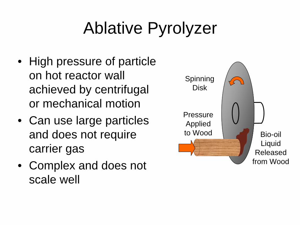
Ablative Pyrolyzer
• High pressure of particle on hot reactor wall achieved by centrifugal or mechanical motion
• Can use large particles and does not require carrier gas
• Complex and does not scale well
Spinning Disk
Pressure Applied to Wood Bio-oil
Liquid Released
from Wood

Vacuum Pyrolysis
• Biomass moved by gravity and rotating scrappers through multiple hearth pyrolyzer with temperature increasing from 200 C to 400 C
• Can use larger particles and employs little carrier gas
• Expensive vacuum pump and difficult to scale-up
Scrapper Driver Biomass
Char
Vacuum pump
Multiple hearth vacuum pyrolysis
reactor
Condensers

Auger Reactor
Biomass
Auger driver
Char & sand
Vapors & aerosol to condenser
Hot sand
Auger reactor
• Hot sand and biomass mixed by auger
• Suitable for small scale
• Requires hot sand heating and circulation system

Relative Merits of Various Reactors
Property Status Bio-oil
wt%
Comp-lexity
Feed size
Inert gas
need
Specific size
Scaleup
Fluid bed Demo 75 Medium Small High Medium Easy
CFB Pilot 75 High Medium High Large Easy
Entrained None 65 High Small High Large Easy
Rotating cone
Pilot 65 High V small Low Small Hard
Ablative Lab 75 High Large Low Small Hard
Auger Lab 65 Low Small Low Medium Easy
Vacuum Demo 60 High Large Low Large Hard
The darker the cell color, the less desirable the process.
Lab: 1 – 20 kg h-1
Pilot: 20 – 200 kg h-1
Demo: 200 – 2000 kg h-1
Adapted from PYNE IEA Bioenergy http://www.pyne.co.uk

Which will dominate?TECHNOLOGY STRENGTH
Strong Average Weak
Ablative
Cyclonic
Rotating cone
Entrained flow
Fluid bed
Circulating fluid bedand transport reactor
AugerMA
RK
ET
AT
TR
AC
TIV
EN
ES
S
High
Low
Adapted from PYNE IEA Bioenergy http://www.pyne.co.uk

Fast Pyrolysis System
Mill
Air
Quencher
Bio-oil Bio-oilstorage
Hopper
Fluidizing gas
Flue gas
Vapor, gas, char products
Cyclone
Combustor
Pyrolysis gases
Lignocellulosicfeedstock
Pyrolysisreactor Char
FeederMotor

Scale
$0
$1,000
$2,000
$3,000
$4,000
$5,000
$6,000
$7,000
$8,000
0.0 1.0 2.0 3.0 4.0 5.0Biomass Input (million US tons/yr)
Cap
ital C
ost (
mill
ion
2005
US
dolla
rs)
0 50 100 150 200 250Diesel Output (million US gallons/yr)
Small gasification (multiple units 110,000US ton/yr) + small FT multiple unitsSmall pyrolysis (multiple units 110,000US ton/yr) + large FTLarge gasification + large FT
$400,000 pbpd
$100,000 pbpd
Adapted from: Bridgwater, ACS Meeting, Washington, D.C., 2005

Suitable Feedstocks
• Wide variety of feedstocks can be used• Fibrous biomass usually employed• Wood higher yielding than herbaceous
biomass

Storage & Transportation
• Distributed preprocessing allows transport and storage as liquid
• High acidity requires storage in stainless steel or plastic
• Stability problems need to be solved

Post Processing to Motor Fuels
• Direct application of bio-oil• Hydrocracking of bio-oil• Gasification of bio-oil• Fermentation of Bio-oil

Bio-Oil Burned in Diesel Engines
• Bio-oil used as directly as diesel fuel substitute• Only suitable for stationary power applications
Pyr
olyz
er
Bio-Oil Recovery
Bio-Oil Storage
Stationary Diesel Engine
Fibrous biomass
Bio-oil vaporCyclone
Bio-OilChar

Bio-Oil Hydrocracking• Directly converts biomass into liquid bio-oil (lignin,
carbohydrate derivatives, and water) and char• Bio-oil catalytically converted into hydrocarbon fuel
(green diesel)
Pyr
olyz
er Carbohydrate derived aqueous phase
Bio-Oil Recovery
Phase Separation
Steam Reformer
Hyd
rocr
acke
r
Fibrous biomass
Bio-oil vapor
Hydrogen
Green diesel
Cyclone
Lignin
Char

Bio-Oil Gasification• Bio-oil and char slurried together to recover 90% of
the original biomass energy• Slurry transported to central processing site where it is
gasified in an entrained flow gasifier to syngas• Syngas is catalytic processed into green diesel (F-T
liquids)
Pyr
olyz
er
Bio-Oil Recovery
Slurry Preparation
Pump
Ent
rain
ed F
low
G
asifi
er
Fibrous biomass
Bio-oil vapor
Slag
Cyclone
Bio-Oil
Char
Fisc
her T
rops
ch
Rea
ctor
Green Diesel

Bio-Oil Fermentation
Fermenter
Fiber
Pyr
olyz
er
Anhydrosugar & other carbohydrate
Bio-Oil Recovery
Phase Separation
Detoxification
Lignin
Hot water extraction
Pentose
Fibe
r byp
rodu
ct Bio-oil vapor
Fermenter
Distillation
Water
Ethanol
Cyclone
Char
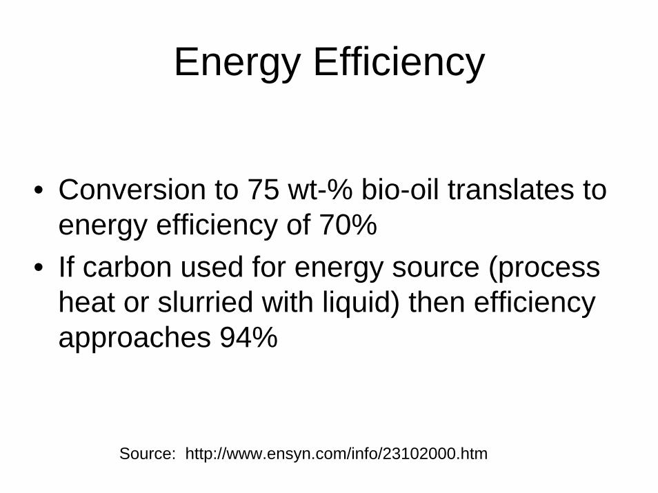
Energy Efficiency
• Conversion to 75 wt-% bio-oil translates to energy efficiency of 70%
• If carbon used for energy source (process heat or slurried with liquid) then efficiency approaches 94%
Source: http://www.ensyn.com/info/23102000.htm

Co-Products
• Gas (CO, H2, light hydrocarbons)– Can be used to heat
pyrolysis reactor• Char: Several potential
applications– Process heat– Activated carbon– Soil amendment

Potential Co-Products from Bio-OilProducts of pyrolysis for several different pretreatments of cornstover (Brown et al. 2001)
No Pretreatment
Acid Hydrolysis
Acid Wash Acid Wash with catalyst
Products (Wt% maf)
Char 15.8 13.2 13.2 15.9
Water 2.57 10.6 10.4 7.96
Organics 59.1 67.2 68.5 67.7
Gases 22.6 9.02 7.88 8.44
Organics (Wt %)
Cellobiosan trace 4.55 3.34 4.97
Levoglucosan 2.75 17.69 20.12 23.10
Hydroxy-acetaldehyde 11.57 5.97 3.73 3.93
Formic acid 2.61 Trace Trace 0.73
Acetic acid 3.40 1.51 1.26 0.40
Acetol 4.53 trace trace trace
Formaldehyde 2.75 1.63 trace 0.70
Pyrolytic lignin 33.40 16.89 17.74 20.08

Quality Assurance
• Bio-oil quality issues:– Moisture content– Particulate content– Sulfur and nitrogen content– Stability

Equipment Maintenance
• Potential problems with pyrolysis equipment– Bed agglomeration– Clogging of condensers– ESP performance
• Catalytic reactors– Poisoning by sulfur and chlorine– Coking

Waste Streams
• Main products (gas, char, bio-oil) account for all mass of biomass feedstock

Technical Barriers
• Preparing dry, finely divided biomass particles
• Maintaining high bio-oil yields• Improving bio-oil stability • Determining optimal scale of facility

Alternative Fuels: TargetsAlternative Fuels: TargetsAlternative fuels may need to target:Alternative fuels may need to target:
–– < 100 gm CO< 100 gm CO22/km WTW /km WTW –– GTL, DME from gas GTL, DME from gas –– close, but close, but
not there yetnot there yet
Several other alternatives in study Several other alternatives in study (not shown for simplicity)(not shown for simplicity)Engine manufacturers developing Engine manufacturers developing more efficient advanced more efficient advanced ICEICE’’ss in in addition to hybrids and FCaddition to hybrids and FC’’ss
–– Variable DI gasolineVariable DI gasoline–– ““Part HomogeneousPart Homogeneous”” diesel diesel
combustioncombustion–– ““Combined CombustionCombined Combustion”” systemssystems–– Improve fuel efficiencyImprove fuel efficiencySource: CONCAWE / EU CAR / Source: CONCAWE / EU CAR /
EU EU CommComm’’nn, , DecDec 20032003
WTW Energy /GHG Emissions Clusters WTW Energy /GHG Emissions Clusters
00
5050
100100
150150
200200
250250
300300
350350
400400
00 200200 400400 600600 800800 10001000Energy, MJ/kmEnergy, MJ/km
GH
G, C
OG
HG
, CO
22E
quiv
alen
t, gm
/km
Equ
ival
ent,
gm/k
m
HydrogenHydrogenfrom coal, FCfrom coal, FCDME from NGDME from NG
FAMEFAMEConventional Conventional EtOHEtOHHydrogen fromHydrogen frombio, ICEbio, ICEGasoline & DieselGasoline & Diesel
GTL from NGGTL from NG
Green DieselGreen Diesel
Gasoline & Diesel in Advanced Gasoline & Diesel in Advanced ICEICE’’ss Set Tough Targets!Set Tough Targets!

Biorenewables and Petroleum Biorenewables and Petroleum Feeds: Relative AvailabilityFeeds: Relative Availability
00
1010
2020
3030
4040
5050
CurrentCurrent PotentialPotential
Liquid Transport FuelsLiquid Transport FuelsDieselDieselAvailable Oil/GreaseAvailable Oil/GreaseCellulosic WasteCellulosic Waste
MB
PDM
BPD
GlobalGlobal USUS
00
22
44
66
88
1010
CurrentCurrent PotentialPotentialM
BPD
MB
PD
Liquid Transport FuelsLiquid Transport FuelsGasolineGasolineDieselDieselAvailable Oil/GreaseAvailable Oil/GreaseCellulosic WasteCellulosic Waste
1212
1414
Available Cellulosic Biomass Could Make a Available Cellulosic Biomass Could Make a Significant Impact in Fuels PoolSignificant Impact in Fuels Pool
UOP 4434A-09

PyPy Oil PortfolioOil Portfolio
SolidCellulosicBiomass
Pyrolysis Oil/Lignin Hydrogen/
Power Generation
Diesel
Gasoline

Lignin Molecular Structure

Treating TechnologiesTreating TechnologiesHydrotreatingHydrotreating
• Hydrotreating is the key process to meet quality specifications for refinery fuel products
• Removes sulfur, nitrogen, olefins, and metals using hydrogen
• Hydrogen addition also improves the quality of distillate fuels (poly aromatics, cetane, smoke point)
• Treating feedstocks for other processing units

Conversion TechnologiesConversion TechnologiesHydrocrackingHydrocracking
• Hydrocracking upgrades heavy feeds including gas oils and cycle oils into lighter, higher value, low sulfur products
• High pressure is used to add hydrogen and produce premium distillate products
• Naphtha products normally are low octane and are upgraded in a reformer
• Product volume is 10-20% higher than the feedstock

Dis
tilla
tes S
elec
tivity
Activity
New GenerationNew Generation
Max Max DieselDiesel DistillatesDistillates
FlexibleFlexible Max Max NaphthaNaphtha
Hydrocracking Catalyst PortfolioHydrocracking Catalyst Portfolio
HCHC--150150
HCHC--2929
HCHC--215215
HCHC--115115
DHCDHC--3232
HCHC--3333
DHCDHC--88
HCHC--2424
HCHC--4343
Current GenerationCurrent Generation
DHCDHC--3939DHC-41DHCDHC--4141
HCHC--3434HCHC--2626
Distillate Selectivity Decreases with Increasing ActivityDistillate Selectivity Decreases with Increasing Activity
HCHC--170170HCHC--190190
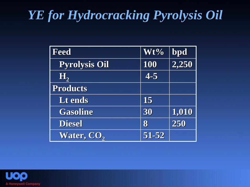
YE for YE for HydrocrackingHydrocracking Pyrolysis OilPyrolysis Oil
FeedFeed Wt%Wt% bpdbpdPyrolysis OilPyrolysis Oil 100100
44--55
15153030885151--5252
2,2502,250HH22
ProductsProductsLt endsLt endsGasolineGasoline 1,0101,010DieselDiesel 250250Water, COWater, CO22

Gasoline Production from Gasoline Production from PyPy OilOil($40/bbl crude)($40/bbl crude)
FeedFeed $/D$/D bpdbpdPyrolysis OilPyrolysis Oil 40,50040,500HH22 25,68025,680 21.4 T21.4 T
19,30319,30352,52052,52012,00012,000
UtilitiesUtilities --4,8004,800Net Net 12,84312,843
2,2502,250
ProductsProductsLt HydrocarbonsLt Hydrocarbons 64T/D64T/DGasolineGasoline 1,0101,010DieselDiesel 250250
$ 4.2 million/year

Hydroprocessing costs: Hydroprocessing costs: Effect of ScaleEffect of Scale
HDT Capital Cost vs Capacity
$0.0$5.0
$10.0$15.0$20.0$25.0
$30.0$35.0
0 5000 10000 15000 20000 25000 30000 35000
Capacity, BPD
Capi
tal C
ost,
$MM
(200
6)Unit size (bpd)
Cost, $MM
Cost/ 1000 bpd
$MM30000 $28.9 0.96$ 27500 $27.4 1.00$ 25000 $25.9 1.04$ 22500 $24.3 1.08$ 20000 $22.7 1.13$ 17500 $20.9 1.19$ 15000 $19.1 1.27$ 12500 $17.1 1.37$ 10000 $14.9 1.49$ 7500 $12.6 1.68$ 5000 $9.9 1.97$ 2500 $6.5 2.60$
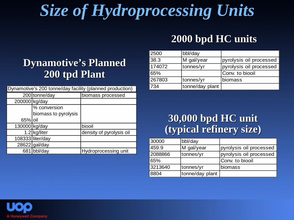
Size of Hydroprocessing UnitsSize of Hydroprocessing Units2000 bpd HC units2000 bpd HC units
2500 bbl/day38.3 M gal/year pyrolysis oil processed174072 tonnes/yr pyrolysis oil processed65% Conv. to biooil267803 tonnes/yr biomass734 tonne/day plant
DynamotiveDynamotive’’ss Planned Planned 200 200 tpdtpd PlantPlant
Dynamotive's 200 tonne/day facility (planned production)200 tonne/day biomass processed
200000 kg/day
65%
% conversion biomass to pyrolysis oil
130000 kg/day biooil1.2 kg/liter density of pyrolysis oil
108333 liter/day28622 gal/day
681 bbl/day Hydroprocessing unit
30,000 bpd HC unit 30,000 bpd HC unit (typical refinery size)(typical refinery size)
30000 bbl/day459.9 M gal/year pyrolysis oil processed2088866 tonnes/yr pyrolysis oil processed65% Conv. to biooil3213640 tonnes/yr biomass8804 tonne/day plant

Example: Example: Potential from logging residuesPotential from logging residues
41 Million dry tons logging residue available (Billion ton annual study)10% % water of biomass for pyrolysis unit
46 Million tons of logging residue feed65% % conversion to pyrolysis oil29.6 million tons of pyrolysis oil
6519 M gallons of pyrolysis oil from logging residue425271 bbl/day
~14 30,000 bpd hydroprocessing units~14 30,000 bpd hydroprocessing units–– Estimated cost: $405 MMEstimated cost: $405 MM
~170 2500 bpd hydroprocessing units~170 2500 bpd hydroprocessing units–– Estimated cost: $1105 MMEstimated cost: $1105 MM

Distributed Pyrolysis Plants; Centralized RefiningDistributed Pyrolysis Plants; Centralized Refining
Integrated into traditionalIntegrated into traditionalnatural gas conversionnatural gas conversion
process or refineryprocess or refinery
Gasif
ier
P P
P P
P P Biomass
Gasification
Natural Gas
DME
Methanol
H2
GTL, BTL
Synthesis GasReforming
Key Decision: What are we planning to Key Decision: What are we planning to transport?transport?

Technical BarriersTechnical Barriers
Securing a consistent Securing a consistent pypy Oil feedstock Oil feedstock Logistics Logistics Balance of distributed vs. centralized Balance of distributed vs. centralized Catalyst and process Catalyst and process invention/development/commercialization invention/development/commercialization

SummarySummaryVegetable oils, grease and pyrolysis oil could be Vegetable oils, grease and pyrolysis oil could be feasible feedstocks for conventional petroleum feasible feedstocks for conventional petroleum refineriesrefineries
–– Other feedstocks and processing options also look Other feedstocks and processing options also look promisingpromising
–– Increased volumes of biobased feedstocks requiredIncreased volumes of biobased feedstocks required•• Consistent source of pyrolysis oil or other Consistent source of pyrolysis oil or other lignocellulosiclignocellulosic
biomassbiomass
Biorenewable processing options identified are Biorenewable processing options identified are not limited to refinery integrationnot limited to refinery integration
–– Stand alone units possibleStand alone units possible•• BiorefineriesBiorefineries; ; BiofeedstockBiofeedstock sourcesource•• Portable HPortable H22
UOP 4434A-36

AcknowledgementsAcknowledgementsDOE, Project DEDOE, Project DE--FG36FG36--05GO15085 05GO15085
Contributors Contributors MTUMTU
–– David David ShonnardShonnardNREL NREL
–– Stefan Stefan CzernikCzernik–– Richard BainRichard Bain
Contributors Contributors PNNL PNNL
–– Doug Elliott Doug Elliott –– Don StevensDon Stevens
UOP UOP –– Tom Kalnes Tom Kalnes –– Terry MarkerTerry Marker–– Dave Mackowiak Dave Mackowiak –– Mike McCallMike McCall–– John PetriJohn Petri
Project Manager: Rich MarinangeliProject Manager: Rich Marinangeli