fast-fission tokamak breeder reactors
TRANSCRIPT
Journal of Fusion Energy, Vol. 5, No. 3, 1986
Fast-Fission Tokamak Breeder Reactors
D. L. Jassby, 1 D. H. Berwald, 2 J. Garner, 2 R. H. Whitley, 2 I. Maya, 3 C. P. C. Wong, 3 J. D. Lee, 4 and R. W. Moir 4
Received December 7, 1985," revised February 12, 1986
A fast-fission blanket around a fusion plasma exploits high neutron multiplication for superior breeding and high-energy multiplication to generate significant net electrical power. A major improvement over previous fast-fission blanket concepts is the use of mobile fuel, namely a pebble-bed configuration with helium cooling. Upon loss of coolant, the mobile fuel can be gravity-dumped to a separately cooled dump tank before excessive temperatures are reached. The pebble bed is also compatible with rapid fuel exchange and a low-cost reprocessing method. With the ignited tokamak plasma producing 620 MW of fusion power, the net electric power is 1600 MW e and the annual fissile production exceeds 3 tonnes.
KEY WORDS: breeder; fast-fission; hybrid; pebble bed; tokamak.
1. INTRODUCTION
The motivations for pursuing a fast-fission blanket for a tokamak fissile breeder are, first, to exploit the high neutron multiplication of U for fissile breeding, and second, to generate significant electrical power output resulting from the substantial blanket energy multiplication M. The large neutron multiplication compared with non fissioning blankets compensates for the inevitably imperfect blanket coverage and parasitic losses in structural material. While fission products are introduced, the problems associated with using beryllium in suppressed- fission blankets (1~ (radiation damage, fabrication
1Princeton Plasma Physics Laboratory, Princeton, New Jersey, 08544.
2Energy Development Group, TRW, Redondo Beach, California 90278.
3GA Technologies, San Diego, California 92138. 4Lawrence Livermore National Laboratory, Livermore, California
94550.
difficulties, uncertain neutronics performance) are avoided.
The high blanket M allows the fast-fission tokamak breeder (FFTB) to have much smaller fu- sion power, wall loading, and physical size than breeders with suppressed-fission blankets in order to be electrically self-sufficient, or to produce a given level of net electrical power. Much larger coil losses and pumping powers per unit of fusion power can be tolerated. In fact, there is considerable excess power for sale, which is probably a more valuable product than the fissile material.
The relatively large afterheat of fast-fission blankets gives rise to more serious concerns (2~. That drawback is addressed by the present improved de- sign concept, which uses a mobile form of uranium that permits rapid draining in case of loss of coolant. Also, a second cooling circuit consisting of tubes immersed in the uranium pebble bed can carry away afterheat. The blanket would be fueled only with natural or depleted uranium, and thus offers a major advantage over competing fission breeders, which must use highly enriched fuel.
171 0164-0313/86/0900-0171505.00/0�9 Plenum Publishing Corporation
172 Jassby et aL
2400
2300
-~ 2200
21oo
2000
1900
b 18oo
1900
1600
I I I I
Fusion Power=3,000 M W / I n d u c t i v ~
Inducfve Drive
1500 I I I I 4 5 6 7 8
MAJOR RADIUS (m)
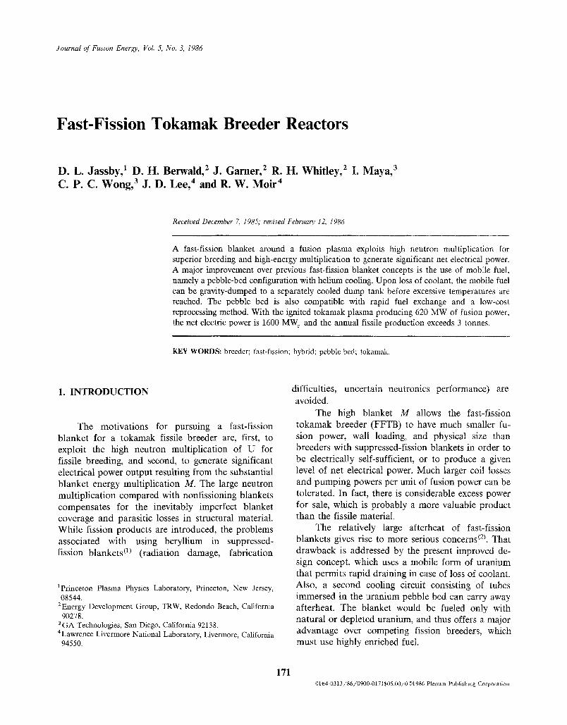
Fig. 1. Variation of direct capital cost with reactor size.
2. TOKAMAK DRIVER DEFINITION
Because of the large blanket M, the fusion plasma could operate with energy gain Q = 10 without seriously affecting the net plant efficiency. That would allow steady-state operation with rf or neutral-beam current drive, and also alleviate ther- mal stability problems. However, cost analysis with a systems code showed that the least capital-intensive machines use ignited plasmas. Furthermore, realizing efficient steady-state current drive is problematical from both physics and engineering considerations, even compared with the difficulties of attaining igni- tion. Thus, the present study opted for fully ignited operation with a transformer-driven current.
2.1. Size Selection
Figure 1 gives the results of a systems study analysis of reactor cost vs. size. Provided that the burn length is at least 1000 sec, the least expensive machine as measured by direct cost per net kW-elec- tric has an ignited plasma with inductive current drive and 5.2-m major radius. The systems model accounts for the duty factor and the increased struc- ture necessary to ensure adequate component life- time in the face of cyclic operation. (The value of the fissile fuel product was not factored into the optimi- zation study.)
2.2. Operating Mode
In the baseline operating mode, the plasma cur- rent is initiated by rf waves at lower hybrid frequency,
the plasma is heated to ignition by ion cyclotron waves, and the plasma current is sustained by the OH (Ohmic heating) primary windings. The OH system drives 2000-sec pulses for a duty factor ex- ceeding 95%. The principal drawback of this mode is its pulsed nature, which introduces serious thermal and mechanical cycling problems. (A larger machine would operate with multihour pulses.)
Current startup by lower hybrid waves has been well-documented experimentally. (31 An optional steady-state operating mode specifies steady-state current drive by 60 MW of 500-keV neutral beams. The electrical power to drive the beams would be 110 MW, or about 6% of the gross electric power output. However, this mode would require development of high-power, steady-state, negative-ion beams, and the extra equipment would result in larger capital cost of the reactor.
2.3. Plasma Systems Description
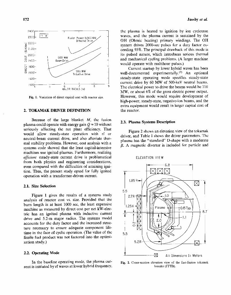
Figure 2 shows an elevation view of the tokamak driver, and Table I shows the driver parameters. The plasma has the "standard" D-shape with a moderate /3. A magnetic divertor is included for particle and
5.5
ELEVATION VIEW
5.5
T [ ] All Dimensions in Meters
Fig. 2. Cross-section elevation view of the fast-fission tokamak breeder (FFTB).
Fast Fission Tokamak Breeder Reactors 173
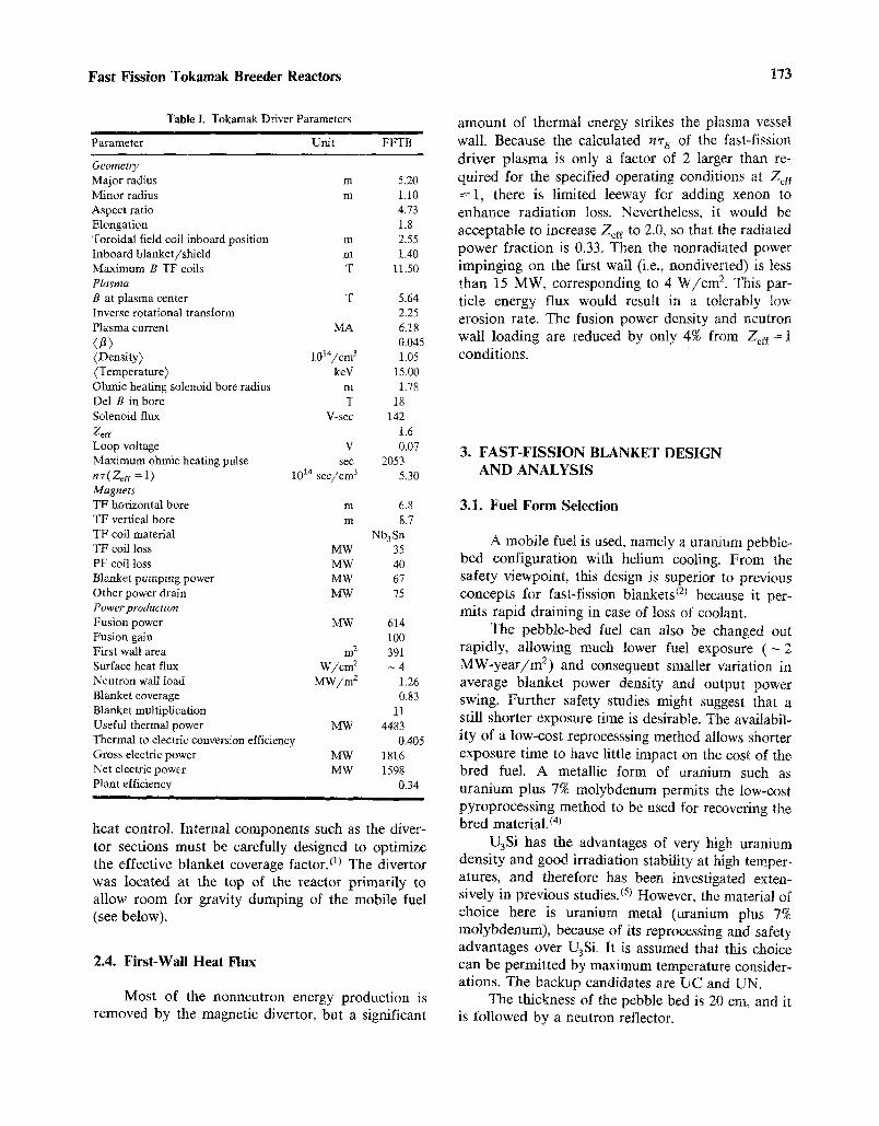
Table I. Tokamak Driver Parameters
Parameter Unit FFTB
Geometry Major radius Minor radius Aspect ratio Elongation Toroidal field coil inboard position Inboard blanket/shield m Maximum B TF coils T Plasma B at plasma center T Inverse rotational transform Plasma current MA
(8) (Density) 1014/cm 3 (Temperature) key Ohmic heating solenoid bore radius m Del B in bore T Solenoid flux V-sec Zeff Loop voltage V Maximum ohmic heating pulse sec n'r( Zeff = 1) 10 TM sec/cm 3 Magnets TF horizontal bore m TF vertical bore m TF coil material TF coil loss MW PF coil loss MW Blanket pumping power M-W Other power drain MW Power production Fusion power MW Fusion gain First wall area m 2 Surface heat flux W/cm 2 Neutron wall load MW/m a Blanket coverage Blanket multiplication Useful thermal power MW Thermal to electric conversion efficiency Gross electric power MW Net electric power MW Plant efficiency
I I I I I
m 5.20 m 1.10
4.73 1.8
m 2.55 1.40
11.50
5.64 2.25 6.18 0.045 1.05
15.00 1.78
18 142
1.6 0.07
2053 5.30
6.8 8.7
Nb 3 Sn 35 40 67 75
614 100 391 - 4
1.26 0.83
11 4483
0.405 1816 1598
0.34
heat control. Internal components such as the diver- tor sections must be carefully designed to optimize the effective blanket coverage factor. 0) The divertor was located at the top of the reactor primarily to allow room for gravity dumping of the mobile fuel (see below).
2.4. First-Wall Heat Flux
Most of the nonneutron energy production is removed by the magnetic divertor, but a significant
amount of thermal energy strikes the plasma vessel wall. Because the calculated n ' r e of the fast-fission driver plasma is only a factor of 2 larger than re- quired for the specified operating conditions at Zaf --1, there is limited leeway for adding xenon to enhance radiation loss. Nevertheless, it would be acceptable to increase Zaf to 2.0, so that the radiated power fraction is 0.33. Then the nonradiated power impinging on the first wall (i.e., nondiverted) is less than 15 MW, corresponding to 4 W/cm 2. This par- ticle energy flux would result in a tolerably low erosion rate. The fusion power density and neutron wall loading are reduced by only 4% from Zef f = I conditions.
3. FAST-FISSION BLANKET DESIGN AND ANALYSIS
3.1. Fuel Form Selection
A mobile fuel is used, namely a uranium pebble- bed configuration with helium cooling. From the safety viewpoint, this design is superior to previous concepts for fast-fission blankets (2) because it per- mits rapid draining in case of loss of coolant.
The pebble-bed fuel can also be changed out rapidly, allowing much lower fuel exposure ( - 2 MW-year/m 2) and consequent smaller variation in average blanket power density and output power swing. Further safety studies might suggest that a still shorter exposure time is desirable. The availabil- ity of a low-cost reprocesssing method allows shorter exposure time to have little impact on the cost of the bred fuel. A metallic form of uranium such as uranium plus 7% molybdenum permits the low-cost pyroprocessing method to be used for recovering the bred material. (4)
U3Si has the advantages of very high uranium density and good irradiation stability at high temper- atures, and therefore has been investigated exten- sively in previous studies. (s) However, the material of choice here is uranium metal (uranium plus 7% molybdenum), because of its reprocessing and safety advantages over U3Si. It is assumed that this choice can be permitted by maximum temperature consider- ations. The backup candidates are UC and UN.
The thickness of the pebble bed is 20 cm, and it is followed by a neutron reflector.
174 Jassby et aL
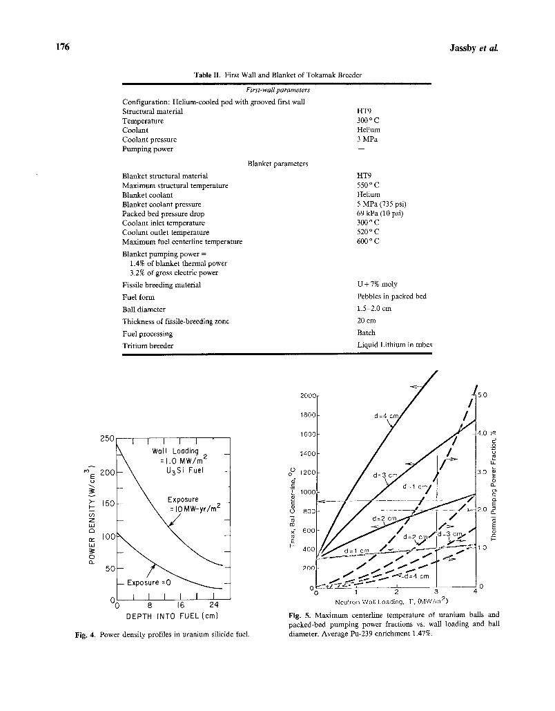
3.2. Mechanical Configuration
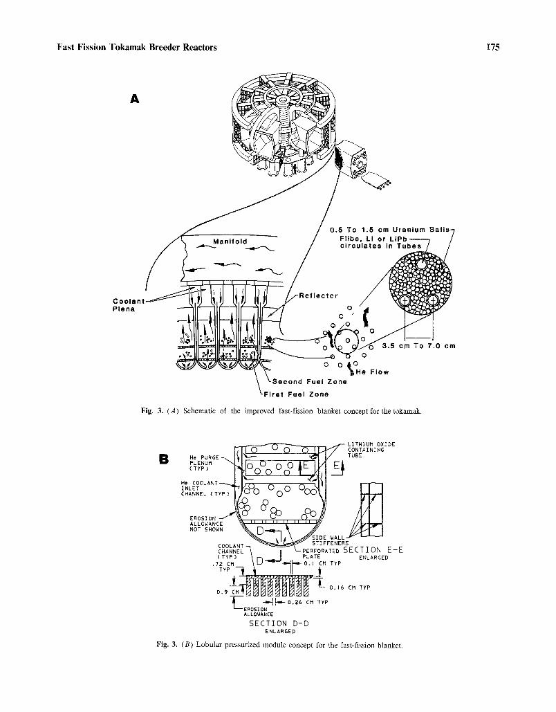
Figure 3a shows the modular blanket concept adopted for the FFTB. The uranium pebbles are contained in lobular pressurized submodules having a thin first wall, as shown in Fig. 3b. The submodules are arranged poloidally around the reactor so that fissile fuel removal can be accomplished without removal of the entire module. Unlike pressure-tube approaches, a relatively small number of joints and connections are needed for helium cooling of the submodules.
The pressure load is carried very efficiently as a pure tensile load in the first-wall structure. This technique results in a thin first wall that provides superior neutron economy for the blanket. The curved shape of the first wall allows coolant to be flowed smoothly across it. The semicircular shape is also naturally swelling-tolerant; thermal expansion and neutron swelling cause only a small bending moment and very small stresses. Mechanical strength for the submodule is provided by a strongback structure at the rear that can be part of the helium inlet/outlet plenum system.
3.3. Tritium Breeder
Tritium-breeding material, which can be lithium, flibe, lithium-lead, LiA102, or Li20, is contained in tubes within and behind the uranium pebble bed. The spacing between the tubes is 3.5-7 cm. Liquid lithium is the tentative choice for the tritium breeder. Most of the lithium is located in a region of relatively soft spectrum, and is highly enriched to reduce the volume required. The lithium is nearly stagnant; its flow rate is only large enough so that the bred tritium can be removed, and the lithium pumping power is insignificant. The nuclear heat deposited in the lithium is eventually transported out of the system by the helium coolant.
3.4. Heat Transfer
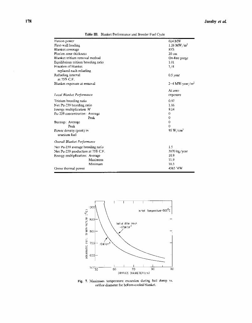
First-wall and blanket thermal characteristics are given in Table II. Heat transfer was evaluated for a helium-cooled U3Si-ball blanket zone of 26 cm thickness. (6~ The volumetric power generation of Pu-239 at a typical enrichment of 1.47% was used in the calculation. Figure 4 shows the power density profile in the uranium fuel bed.
The U3Si ball centerline temperature and ther- mal pumping power fraction were calculated as a function of neutron wall loading and U3Si ball diam- eter, and the results are shown in Fig. 5. At the design value of 1.25 MW/m 2 and a ball diameter of 2 cm, the ball maximum temperature is about 600 ~ C, and the pumping power for the packed bed is 1.4% of the reactor thermal power.
The preferred breeding materials, uranium metal, UN, or UC, will also operate satisfactorily at the power densities considered here. Further study is needed to determine whether uranium metal (uranium plus 7% molybdenum) can be retained as the material of choice.
3.5 Neutronics
The neutronics performance of the pebble-bed blanket is essentially the same as that of the helium- cooled fast-fission blanket analyzed in refs. 5 and 6, provided that the relative atomic concentrations are similar. The uranium for this previous blanket was in the form of Inconel-clad U3Si, but performance should be approximately the same for uranium metal, UN, or UC.
Figure 6 gives the blanket performance as a function of exposure (integrated fluence). Table lII summarizes the blanket performance parameters and breeder fuel cycle.
4. MOBILE FUEL SAFETY ISSUES
The afterheat in the uranium carbide fuel near end-of-life (2 MW-year/m 2) is 5-10 W/cm 3, result- ing in an adiabatic heating rate of - 5 ~ at shutdown. Thermal analysis indicates that the breeder fuel must be removed relatively quickly from the reactor in a loss-of-coolant event, in order to prevent melting, structural damage, or radioactive aerosal release. (7) In the present concept, the helium-cooled fuel is gravity-dumped to a separately cooled dump tank before excessive temperatures are reached.
Gravity dumping of the fuel is limited by space considerations. Fuel temperature rise vs. dump orifice diameter is analyzed in ref. 7. Figure 7 gives the required diameter of the dump orifice as a function of maximum adiabatic fuel temperature for the helium-cooled blanket. (8~ An opening diameter of 40-50 cm will allow the fuel to be gravity-dumped before the fuel or structure is damaged by excessive temperatures. Ducts of this diameter are difficult to
Fast Fission Tokamak Breeder Reactors 175
A
Coolant Plena
Manifold
0 .5 To 1.5 cm Uranium Balls-
/ Flibe, Li or L iPb- - - - - - 7 c i rcula tes in Tubes /
o( 0 '
0 / 0
~@ ~ 0 0 0
e Flow Second Fuel Zone
t-First Fuel Zone
Fig. 3. (A) Schematic of the improved fast-fission blanket concept for the tokamak.
. ~,-- LITHIUM OXIDE CONTAINING
I He PURGE -~ TUBE
PLENUM " ' ~ 1 Ir'i C) r~ ( ~ I/1 ~"
He COOLANT-~..L_I)F. ~ ,~ _ ,--, "~1 | [ INLET -'[~I"f"~'",""h u _ 0 v,--v-,"i I I I I CHANNEL ( TYP~((@ v ( ~ 2 .,--.~ I) / / ~
EROSION --I- \\ ~ // /4 1 I ALLOWANCE \ \ / / / / ~ NOT SHO.N ~ D " - ~ "~ f Y/JIll_ I
~.~ ,1~ \ ~.~SIDE WALL ~ "-'--~-- COOLANT ~ ~ ' ~ STIFFENERS ~I~EL'-~ ~--f'k--PERFORATED SECTION E-E ( TYP ) ~ r-', __ I PLATE ENLARGED
.72 CM \LP''~"-i~'II--i- O.I CM TYP TYP , ~ i
0,9 E M ~ M ~ - ~ - ~ - - ' - L 0. '6 CM TYP -1"---- - - u N ~ E ~ O S ~ -' '~l~l~I- 0 .26 CM TYP
ALLOWANCE
SECTION D-D ENLARGED
Fig. 3. (B) Lobular pressurized module concept for the fast-fission blanket.
176 Jassby et al.
Table II. First Wall and Blanket of Tokamak Breeder
First-wall parameters
Configuration: Helium-cooled pod with grooved first wall Structural material Temperature Coolant Coolant pressure Pumping power
Blanket structural material Maximum structural temperature Blanket coolant Blanket coolant pressure Packed bed pressure drop Coolant inlet temperature Coolant outlet temperature Maximum fuel centerline temperature
Blanket pumping power = 1.4% of blanket thermal power 3.2% of gross electric power
Fissile breeding material
Fuel form
Ball diameter
Thickness of fissile-breeding zone
Fuel processing
Tritium breeder
Blanket parameters
HT9 300 o C Helium 3 MPa
HT9 550 o C Helium 5 MPa (735 psi) 69 kPa (10 psi) 300 o C 520 o C 600 o C
U + 7% moly
Pebbles in packed bed
1.5-2.0 cm
20 cm
Batch
Liquid Lithium in tubes
250
200 E
>- 150 F-
Z
C I
a: I00 t./,.l
12) I1
50
I ] I I I I
_ _ ~ W a l l 2 - Loading = 1.0 MW/m
_ U3Si Fuel _ -
Exposure _
-- Exposure =0 ~ -
I I I I I 1 ) 8 16 24
DEPTH INTO FUEL(cm)
Fig. 4. Power density profiles in uranium silicide fuel.
c" o
Lt_
O o
c o-
L a
f-) O_ % -~ m E
k-
~ 0 1 2 3 4 Neutron WaITLoadlng, r,(tdW/m 2)
Fig. 5. Maximum centerline temperature of uranium balls and packed-bed pumping power fractions vs. wall loading and ball diameter. Average Pu-239 enrichment 1.47%.

Fast Fission Tokamak Breeder Reactors 177
2_
= o"
- 2 z z ~ F - , <::' < LJ
m,_ 7 , m;
> - - J
l..u - - t---
2 . 5 1 1 1 1 1 1 1 1 i I I
2.0
1.5
r .O
0.5
T/n ~ '~ ~ Standard Oeviafi0n ~5% :~
O 0
- ] . 0 4 ~ ~
,,=,~
-~ ).03 co co oo
0.02 m m El_ [ I ] a_m"
~0.01 c~z J E l : t
[~Cr]
taJUa
0 2 4 6 8 I0 coco COO') E X P O S U R E - M W Y / m 2 ~ -
Fig. 6. Local blanket performance vs. neutron exposure. Fission zone thickness 26 cm.
incorporate on the inboard side of the plasma, but still appear feasible.
The "af terheat" in the lithium tubes is very small. Furthermore, in the event of loss of the helium coolant the pumping rate of the lithium can be increased in order to remove heat from the reactor. This capability in effect provides an additional emergency cooling system.
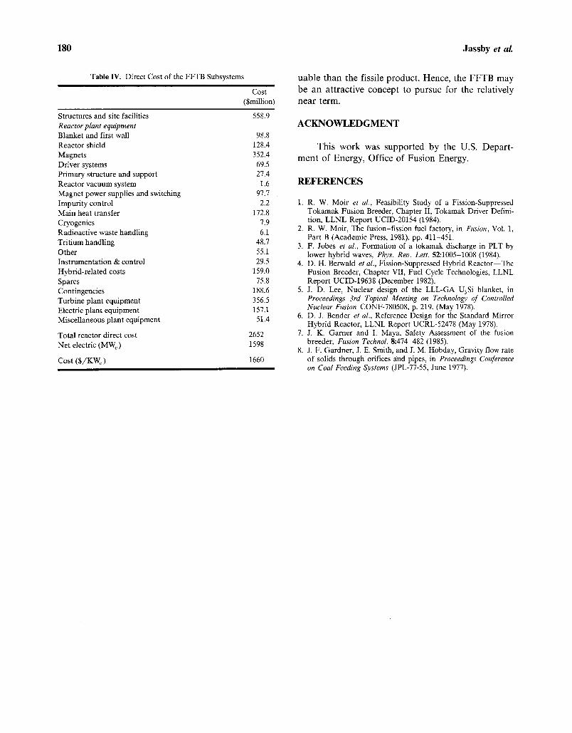
5.2. Direct Cost
Table IV summarizes the direct costs of the reactor components and facilities. The total direct plant cost is estimated as $2700 million (1984). In- cluding indirect costs, the unit capital cost is in the range $2500-3000/kW e (net), or the same range as present LW R capital costs in the United States.
5. C O S T ANALYSIS
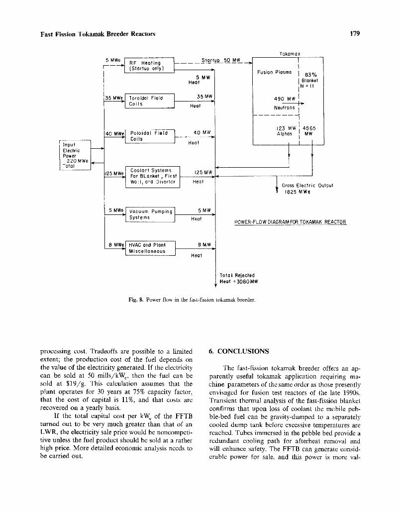
5.1. Power Flow
Figure 8 gives the power flow diagram for the plant. The net electrical efficiency, defined as the ratio of net electric power to the total thermal power, is 0.34 for a conversion efficiency of 0.40, assuming that none of the nonnuclear thermal power (125 MW) is converted.
5.3. Cost of Fissile Fuel and Electricity Products
Using the production numbers given in Table III, we obtain a ratio of electricity revenue to plutonium revenue of 3.4P 1 (mi l l s /kW-hr) /p 2 (S/g). For typical values of electricity (P1 = 30-60) and fuel (P2 = 20-50), more than 3 /4 of the revenue would come from electricity sales.
The total capital cost of the FFTB determines the prices at which it must sell net electricity and fissile fuel, although the latter depends also on re-
178 Jassby et aL
Table III. Blanket Performance and Breeder Fuel Cycle
Fusion power First-wall loading Blanket coverage Fission zone thickness Blanket tritium removal method Equilibrium tritium breeding ratio Fraction of blanket
replaced each refueling Refueling interval
at 7570 C.F. Blanket exposure at removal
Local Blanket Performance
Tritium breeding ratio Net Pu-239 breeding ratio Energy multiplication M Pu-239 concentration: Average
Peak Burnup: Average
Peak Power density (peak) in
uranium fuel
Overall Blanket Performance
Net Pu-239 average breeding ratio Net Pu-239 production at 75% C.F. Energy multiplication: Average
Maximum Minimum
Gross thermal power
614 MW 1.26 M W / m 2 8370 20 cm On-line purge 1.01 1 /4
0.5 year
2-4 MW-year/m 2
At zero exposure
0.97 1.86 9.14 0 0 0 0 95 W//cm 3
1.5
3070 kg/year 10.9 11.9 10.3 4565 MW
IOOC
o v
90C
:~ 80C
d u_ 70C C~
60C
50C
I I I I I I I
Initial Temperature = 500~
\ \ Initial After Heat \ \ :lrW/cm ~
I I I I I I I ,0 50 70 90 I10
ORIFICE DIAMETER (cm)
Fig. 7. Maximum temperature excursion during fuel dump vs. orifice diameter for helium-cooled blanket.
Fast Fission Tokamak Breeder Reactors 179
Input Electric Power
220 MWe Total
5MWe I RF Heating I - - - - - ~ (Stortup only) /
•W._• To ro ida I Field Coils
Poloidal Field J Coils
Coolant Systems 125MWe For BLanket, First
v Wall, and Divertor
Vacuum Pumping Systems
~ HVAC end Plant Miscellaneous
Star tuL50 _MW_._ -
5 MW Heat
35 MW
Heat
40 MW
Heat
125 MW
Heat
5MW IP
Heat
8MW
Heat
Tokamak I I
Fusion Plasma I 83% Blanket
M=I I
490 MW ]
Neutrons
123 MW 4565 Alphas MW
I Gross Electric Output 1825 MWe
POWER-FLOW DIAGRAM FOR TOKAMAK REACTOR
Tota I Rejected Heat = 3080MW
Fig. 8. Power flow in the fast-fission tokamak breeder.
processing cost. Tradeoffs are possible to a limited extent; the production cost of the fuel depends on the value of the electricity generated. If the electricity can be sold at 50 mills/kWe, then the fuel can be sold at $19/g. This calculation assumes that the plant operates for 30 years at 75% capacity factor, that the cost of capital is 11%, and that costs are recovered on a yearly basis.
If the total capital cost per kWe of the FFTB turned out to be very much greater than that of an LWR, the electricity sale price would be noncompeti- tive unless the fuel product should be sold at a rather high price. More detailed economic analysis needs to be carried out.
6. CONCLUSIONS
The fast-fission tokamak breeder offers an ap- parently useful tokamak application requiring ma- chine parameters of the same order as those presently envisaged for fusion test reactors of the late 1990s. Transient thermal analysis of the fast-fission blanket confirms that upon loss of coolant the mobile peb- ble-bed fuel can be gravity-dumped to a separately cooled dump tank before excessive temperatures are reached. Tubes immersed in the pebble bed provide a redundant cooling path for afterheat removal and will enhance safety. The FFTB can generate consid- erable power for sale, and this power is more val-
180 Jassby et al.
Table IV. Direct Cost of the FFTB Subsystems
Cost ($million)
Structures and site facilities 558.9 Reactor plant equipment Blanket and first wall 98.8 Reactor shield 128.4 Magnets 352.4 Driver systems 69.5 Primary structure and support 27.4 Reactor vacuum system 1.6 Magnet power supplies and switching 97.7 Impurity control 2.2 Main heat transfer 172.8 Cryogenics 7.9 Radioactive waste handling 6.1 Tritium handling 48.7 Other 55.1 Instrumentation & control 29.5 Hybrid-related costs 159.0 Spares 75.8 Contingencies 188.6 Turbine plant equipment 356.5 Electric plant equipment 157.1 Miscellaneous plant equipment 51.4
Total reactor direct cost 2652 Net electric (MW e) 1598
Cost ($/KW e) 1660
u a b l e t h a n the fissile p roduc t . Hence , the F F T B m a y
b e a n a t t r ac t ive concep t to p u r s u e for the re la t ively n e a r te rm.
ACKNOWLEDGMENT
Thi s w o r k was suppo r t ed by the U.S. Depa r t - m e n t of Ene rgy , Off ice of F u s i o n Energy.
REFERENCES
1. R. W. Moir et al., Feasibility Study of a Fission-Suppressed Tokamak Fusion Breeder, Chapter II, Tokamak Driver Defini- tion, LLNL Report UCID-20154 (1984).
2. R. W. Moir, The fusion-fission fuel factory, in Fusion, Vol. 1, Part B (Academic Press, 1981). pp. 411-451.
3. F. Jobes et al., Formation of a tokamak discharge in PLT by lower hybrid waves, Phys. Rev. Lett. 52:1005-1008 (1984).
4. D. H. Berwald et al., Fission-Suppressed Hybrid Reactor--The Fusion Breeder, Chapter VII, Fuel Cycle Technologies, LLNL Report UCID-19638 (December 1982).
5. J. D. Lee, Nuclear design of the LLL-GA U3Si blanket, in Proceedings 3rd Topical Meeting on Technology of Controlled Nuclear Fusion CONF-780508, p. 219. (May 1978). D. J. Bender et al., Reference Design for the Standard Mirror Hybrid Reactor, LLNL Report UCRL-52478 (May 1978). J. K. Garner and I. Maya, Safety Assessment of the fusion breeder, Fusion Technol. 8:474-482 (1985). J. F. Gardner, J. E. Smith, and J. M. Hobday, Gravity flow rate of solids through orifices and pipes, in Proceedings Conference on Coal Feeding Systems JPL-77-55, June 1977).
6.
7.
8.