fall 2010 engineering dynamics corporation … · · 2014-08-21fall 2010 engineering dynamics...
TRANSCRIPT
FALL 2010 ENGINEERING DYNAMICS CORPORATION
Version 8.1 of HVE, HVE-2D and the new HVE-CSI iscurrently undergoing final development and testingprograms, with the expectation they will be released bythe end of the year. This latest version offers usersexciting new features, such as:
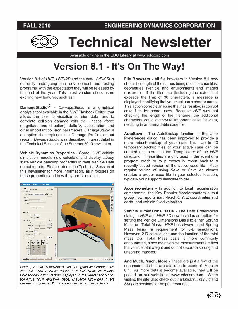
DamageStudio� - DamageStudio is a graphicalanalysis tool available in the HVE Playback Editor, thatallows the user to visualize collision data, and tocorrelate collision damage with the kinetics (forcemagnitude and direction), delta-V, acceleration andother important collision parameters. DamageStudio isan option that replaces the Damage Profiles outputreport. DamageStudio was described in great detail inthe Technical Session of the Summer 2010 newsletter.
Vehicle Dynamics Properties - Some HVE vehiclesimulation models now calculate and display steadystate vehicle handling properties in their Vehicle Dataoutput reports. Please refer to the Technical Session ofthis newsletter for more information, as it focuses onthese properties and how they are calculated.
File Browsers - All file browsers in Version 8.1 nowcheck the length of the names being used for case files,geometries (vehicle and environment) and images(textures). If the filename (including the extension)exceeds the limit of 30 characters, a message isdisplayed identifying that you must use a shorter name.This action corrects an issue that has resulted in corruptcase files for some users. Because HVE was notchecking the length of the filename, the additionalcharacters could over-write important case file data,resulting in an unreadable case file.
AutoSave - The AutoBackup function in the UserPreferences dialog has been improved to provide amore robust backup of your case file. Up to 10temporary backup files of your active case can becreated and stored in the Temp folder of the HVEdirectory. These files are only used in the event of aprogram crash or to purposefully revert back to arecently saved version of the active case file. Yourregular routine of using Save or Save As alwayscreates a proper case file in your selected location,typically your supportFiles/case folder.
Accelerometers - In addition to local accelerationcomponents, the Key Results Accelerometers outputgroup now reports earth-fixed X, Y, Z coordinates andearth- and vehicle-fixed velocities.
Vehicle Dimensions Basis - The User Preferencesdialog in HVE and HVE-2D now includes an option forsetting the Vehicle Dimensions Basis to either SprungMass or Total Mass. HVE has always used SprungMass basis (a requirement for 3-D simulation).However, 2-D calculations use the location of the totalmass CG. Total Mass basis is more commonlyencountered, since most vehicle measurements reflectthe vehicle total weight and do not separate sprung andunsprung masses.
And Much, Much, More - These are just a few of theenhancements that are available to users of Version8.1. As more details become available, they will beposted on our website at www.edccorp.com. Whenvisiting the site, also check out the Library, Training andSupport sections for helpful resources.
Available on-line in the EDC Library at www.edccorp.com
Technical Newsletter
Version 8.1 - It's On The Way!
����������� �� ����� ������� �� � �� ��� ��� � ���� ������� �� ���� � ����� ���� ��� ��� ����� ����������������� ����� ������ �� ����� � ��� ����� ��� ������ ������ ����� ��� ���� � ���� ��� ����� ���� ��� � ������� ��� �� ���� �� ! ��� � ���� ������� ��� ��������

Technical SessionThis Technical Session provides an overview of thevehicle dynamics properties now presented by someHVE vehicle simulation models. The following steadystate vehicle handling properties are now calculatedand displayed in the Vehicle Data output report:
�Understeer Gradient�Roll Gradient�Roll Couple Distribution� Steering Wheel Sensitivity�Weight Distribution
These properties may be new to some users, so we’llexplain what they mean and how they are calculated.Notice that they are called steady state handlingproperties. That means that these properties describethe handling of a vehicle driven under control and wellbelow the limit threshold.
Understeer GradientUndersteer Gradient, or simply Understeer, U (commonunits, deg/g) is perhaps the single most importantdescriptor of vehicle handling. Understeer describeshow much steering (at the tire) is required in addition tothe theoretical amount predicted by simple Ackermannsteering. Ackermann steering is defined solely by thegeometry of a turning vehicle, as shown in Figure 1.
For example, if a vehicle has a 10 ft. wheelbase andattempts to negotiate a 200 ft. radius turn, the amount ofAckermann steering at the tire is:
δ = ⎛
⎝⎜
⎞
⎠⎟ =
⎛
⎝⎜
⎞
⎠⎟ =atan atan deg
WB
R
10
200286.
Note that this value is defined at the tire. If you want toknow how much steering is required at the steeringwheel, simply multiply the steer angle at the tire by thevehicle’s steering gear ratio. For example, if thesteering gear ratio is 18.0 (degrees at the steeringwheel per degree at the tire), the required steeringwheel angle is
δ�� = × =286 180 515. . . deg
If, because of various vehicle loading, suspension,steering system and tire effects, the driver needs tosteer more than 51.5 degrees at the steering wheel tonegotiate the 200 ft radius turn, the vehicle hasundersteer. If, for the same reasons, the driver needs tosteer less than 51.5 degrees at the steering wheel, thevehicle has oversteer. It’s that simple. (By the way,oversteer is simply negative understeer.) If the requiredsteer angle is exactly equal to the Ackermann steerangle, the vehicle has neutral steer.
So how is understeer calculated? Total understeer isthe sum of several individual understeer components:
Weight Distribution and Tires, U� – This is by far thesingle most important handling predictor, a function ofthe tire loads and cornering stiffness at the front andrear tires:
UW
C
W
C
� �
� �
� = −α α
whereW��� = load on the front and rear axlesC���� = tire cornering stiffness for the
front and rear tires (sum of rightand left sides)
F,R = subscripts for front and rear axles
Inspection of the above equation for U� reveals someincredibly useful information. It shows that if front andrear cornering stiffness are equal, a vehicle will beundersteer if the weight on the front axle is greater thanthe weight on the rear axle. It shows that as you addweight to the rear axle (e.g., put a large load in the trunkor the bed of a pickup) or reduce the cornering stiffnessof a rear tire (e.g., reduce the inflation pressure), avehicle normally having understeer handlingcharacteristics can become oversteer! There are lots ofvariations on this theme.
Technical Newsletter FALL 2010
2
������ � � ����� ����� � ��� ���� ����
δ = ⎛
⎝⎜
⎞
⎠⎟atan
WB
R

Suspension and Tires, U� – A smaller but importantcontributor to understeer is caused by the suspensionroll camber and tire stiffness:
UC
C
d
d
C
C
d
d
d
da� �
� =⎛
⎝⎜⎜
⎞
⎠⎟⎟ −
⎛
⎝⎜⎜
⎞
⎠⎟⎟
⎛
⎝
⎜⎜
⎞
⎠
⎟⎟
γ
α
γ
α
γ
φ
γ
φ
φ
�
whereC� = tire cornering stiffness for the
front and rear tires (sum of rightand left sides)
C� = tire camber stiffness for thefront and rear tires (sum of rightand left sides)
d
d
γ
φ= Camber change coefficient (a function
of suspension design) for the frontand rear suspensions (see below)
d
da�
φ= Roll Gradient (see below) for the
front and rear suspensions
d
d
γ
φIs a change in wheel camber due to vehicle body roll.
It occurs in nearly all independent suspension, and hasa value near unity (slightly + or -, depending on whethercamber increases or decreases due to roll.
Suspension, U� – Roll steer in the suspensionincreases or decreases understeer, depending onsuspension and steering linkage design:
( )Ud
da� �
�
� = +ε εφ
where
� = Roll steer coefficient (due to sus-pension and steering linkage design)
There are four additional factors that typically play alesser role and are not included in our calculation:
Suspension Compliance, U� – Compliance in suspensionbushings increases or decreases understeer, againdepending on suspension design.
Steering Compliance, U� – Compliance in the steeringlinkage increases understeer.
Tire Self-aligning Torque, U� – Self-aligning torque issmall in today’s radial tires. Inside and outside tires tendto offset each other.
Tire Rolling Resistance, U� – Rolling resistance also verysmall, but can become a factor for under-inflated tires.
The HVE Vehicle Model does not include suspension orsteering compliance.
U� - U� are ignored in HVE’s Total Understeercalculation, thus:
U U U U� = + +� � �
Roll Gradient
Roll Gradient,d
da�
φ, (common units, deg/g) is the vehicle
roll angle per unit of lateral acceleration. In simpleterms, it defines how much the vehicle rolls whenturning. Roll Gradient is calculated as follows:
d
da
W h W hd
dW h
d
d
K�
� � � �
�
� �
�
�
φ
γ
φ
γ
φ
φ
=
+⎛
⎝⎜⎜
⎞
⎠⎟⎟ +
⎛
⎝⎜⎜
⎞
⎠⎟⎟
+K W h W hd
dW h
d
d�� � � �
�
� �
�
φ
γ
φ
γ
φ− −
⎛
⎝⎜⎜
⎞
⎠⎟⎟ −
⎛
⎝⎜⎜
⎞
⎠⎟⎟
� �
whereW� = Sprung weighth� = Distance from sprung mass CG
to roll center axis, downward +W� = Unsprung weight for front and
rear axlesh� = Elevation of unsprung mass CG
for the front and rear axlesK� = Roll stiffness for the front and rear
suspensions
Roll Couple Distribution
Roll Couple Distribution (common units, %/100) is thefraction of the total vertical load shift to the outside tiresof each axle during a steering maneuver. It isdetermined by the vehicle’s suspension properties andweight distribution. It is calculated as follows:
RCDTW
TW
W z W hd
d
W z W hd
�
�
� � � �
� � � �
=
+ −⎛
⎝⎜⎜
⎞
⎠⎟⎟ +
⎛
⎝⎜⎜
+ −
1
1
γ
φ
γ
φd
⎛
⎝⎜⎜
⎞
⎠⎟⎟ +
⎛
⎝⎜⎜
⎧
⎨
⎪⎪
⎩
⎪⎪
K W hd
d
d
d
d
da
K W hd
d
� �
� �
� �
φ
φ
γ
φ
γ
φ
φ
γ
φ
+ −⎛
⎝⎜⎜
⎞
⎠⎟⎟⎞
⎠⎟⎟
+
1
1−⎛
⎝⎜⎜
⎞
⎠⎟⎟⎞
⎠⎟⎟
⎫
⎬
⎪⎪
⎭
⎪⎪
d
d
d
da� �
γ
φ
φ
FALL 2010 Technical Newsletter
3

whereTW = Track width for the front and
rear axles
Roll Couple Distribution should be slightly greater thanthe fraction of total vehicle weight on the front axle.That’s because during cornering, if the weight shift isgreater on the front axle, the vehicle’s understeertendency will increase. This is desirable, sinceincreasing oversteer under heavy cornering wouldpotentially lead to a spin-out.
Roll Couple Distribution is a parameter that allows a2-D simulation model (i.e., a model that does notdirectly include the effects of suspension rates andanti-sway bars) to approximate the effects of lateralload transfer during cornering. This approach, used byEDSMAC4, is referred to as quasi-static load transfer.
Steering Wheel SensitivitySteering Wheel Sensitivity (units, deg/g) is the amountsteering wheel input required to produce a given lateralacceleration at a given speed (it is sometimespresented as the reciprocal and called LateralAcceleration Gain, g/deg, but the concept is identical).Steering Wheel Sensitivity is calculated as follows:
SWSWB g
VU�=
×+⎛
⎝⎜
⎞
⎠⎟η
�
where
� = Steering gear ratioV = Velocityg = Gravity constant
The velocity used in the equation is arbitrary (HVE uses60 mph). However, it is important to use the samevelocity when comparing the Steering Wheel Sensitivityof different vehicles.
An ExampleThe handling descriptors described above arepresented as part of the Vehicle Data output report forsome physics programs, e.g., SIMON (see Figure 2).
The information in Figure 2 may be interpreted asfollows:
� The vehicle, a 1984 Honda Accord 2-DrHatchback, has understeer characteristicsduring steady-state steering maneuvers (U� hasa positive value). The front tires will need to besteered 1.65 degrees more than the angledefined by Ackermann steering in order toperform a 1-g turn (of course, the vehicle cannotachieve that level of lateral acceleration, but theconcept of understeer has nothing to do withwhat happens during a limit maneuver).
� The Steering Wheel Sensitivity tells us the drivermust turn the steering wheel 68.18 degrees toperform a 1-g turn at 60 mph (same comment asabove applies regarding limit maneuvers).
� The Roll Gradient tells us the vehicle roll anglewill be 2.84 degrees during a 1-g steeringmaneuver (same comment as above).
� The Roll Couple Distribution tells us that whilecornering, 69 percent of the lateral load shift istransferred to the outside front tire and 31percent is transferred to the outside rear tire.
� The Weight Distribution tells us the static load onthe front tires is 59 percent of the total vehicleweight; the static load on the rear tires is 41percent of the total weight.
� The static load on the front tires is 1317.7 lb; thestatic load on the rear tires is 900.23 lb.
Want to learn more about how these andother vehicle dynamics properties affect
vehicle handling and controllability?
Sign up now to attend theTheoretical & Applied VehicleDynamics workshops at the
2011 HVE Forum.
4
Technical Newsletter FALL 2010
������ � � �"# $ ������ ���� ������ ���� �������������� ��� � ���������� �����
2011 HVE FORUMSign Up Today!
The 2011 HVE Forum is the perfect opportunity to gettrained on using the latest features and capabilities ofHVE, HVE-2D and the newest member of the HVEfamily, HVE-CSI. The 2011 HVE Forum offers a wideselection of workshops designed for beginning,intermediate and advanced users, along with User’sGroups, the HVE White Paper session and social hoursat the end of each day. Highly anticipated workshopsat this year's event include:
Advanced HVE
If you’re looking to make the most of HVE‘s newesttools and capabilities using a hands-on approach, thisis the workshop for you. The Advanced HVE Workshopfor 2011 focuses on DamageStudio. The followingtopics are covered:
�High-level Overview
�Description of CollisionData
�Description of DamageStudio
�DamageStudio Applications and Examples(Hands-on)
Introduction to HVE-CSI
This workshop series is designed for the new HVE-CSIuser who wants to gain a basic understanding of how touse HVE-CSI to reconstruct vehicle crashes andloss-of-control scenarios with the EDCRASH andEDSMAC physics programs. The following topics arecovered:
� Introduction to the HVE-CSI User Interface.
�Creating Vehicles
�Creating Environments
�Creating EDCRASH Events
�Creating EDSMAC Events
�Creating Outputs
Environment Modeling for theProfessional Graphic Artist
This workshop is designed to give the professionalgraphic artist using 3D Studio Max the backgroundrequired to properly build 3-D environment models foruse in HVE. The course content will providestep-by-step instructions for the construction of customenvironments that are easily imported into HVE.
3-D Humans: GATB
This workshop provides an overall understanding ofhow to use the GATB model to study occupants andpedestrians in car crashes. The following topics arecovered:
�HVE Human Editor
�Human Parameters
�GATB - Graphical Articulated Total Body
� Examples - Occupants and Pedestrians
The 2011 HVE Forum Registration Booklet, containingthe workshop schedule, descriptions, registration formand hotel information, is available to download fromwww.edccorp.com/2011HVEForum. If you have anyquestions about the events for the week or would likeassistance with selecting your workshops, pleasecontact EDC Customer Service at 503.644.4500.
5
FALL 2010 Technical Newsletter

The Hottest Add-ons andUpgrades of 2010
Thinking about additional capabilities for your systemsoftware or an upgrade to the next level? With the endof the year approaching, now is the perfect time tocontact EDC for options to enhance your software.Here are the "hottest" add-ons and upgrades of 2010:
SIMON and DyMESH
SIMON was specifically designed to take advantage ofthe rich feature set available in the HVE 3-D simulationenvironment, including the HVE Brake Designer, ABSSimulation Model, HVE Driver Model, Tire-TerrainModels, Tire Blow-out Model and the patentedDyMESH 3-D Collision Model. SIMON has beenvalidated against several well-instrumented vehiclehandling studies, including combined steering andbraking, severe irregular terrain traversal, rollover tests,staged crash tests and tire blow-out experiments.
HVE-2D+
HVE-2D users now have the option to upgrade toHVE-2D+. This option converts the regular HVE-2Dviewers to those used by HVE, allowing the user toposition the camera anywhere and look everywhere in a3-D world. This also allows HVE-2D+ users to easilywork with ground level views and target-followingcameras, such as those used for displaying the driver’sview of an impending crash.
HVE-CSI
HVE-CSI is now the first choice for law enforcementcrash reconstructionists and long-time EDC softwareusers upgrading from their trusted EDVAP DOSprograms. HVE-CSI provides momentum- anddamage-based reconstruction calculations, as well astime-based simulation calculations, to confirm vehiclespeeds at loss of control and impact. EDCRASH andEDSMAC, the two reconstruction software toolsincluded with HVE-CSI, have been extensivelyvalidated using actual crash tests. Results have beenaccepted in courts worldwide for over 25 years.
6
Technical Newsletter FALL 2010
��� ��� %�� ������ �� � &'(�)�* ����� ��� ������ ��� ����� ����� ��������� ���� �� ����� �� ��+����� � ��� (��#,�- ���� ������ ����� ����������� �����
��� ��������� � ��� � ����������� � &'(���" ����
(��.,�& � ��������� � ��� � ���� ��� ��� ������' � ��
�������������� ����������/'��� � �0� � ��� � ���
��� ���� ���� ���� � ��� ������� ���� ���� � ���
��� ��������� ��� &'( � � � �"# $ ������� ���� �
������� �� ��������� ����� ������� �� �/' ��� �
�0� � ,� ����� ������ � �"# $ � ���������� %�� ������
������� ��� ��� ��#(�&%�� ��������� � ����������
����� ��� � ��� �������� � ��� ������� �������� ���
������ ������ � � ���� %�� ����� ��������

HVE and HVE-2D F.A.Q.This section contains answers to frequently asked
questions submitted to EDC Technical Support staff by
HVE and HVE-2D users.
Q. I am an HVE-2D user working with the Distance Toolto measure the distance between two vehicles in anEDSMAC4 simulation. When I select a point on onevehicle and then select a point on the other vehicle, Isee the Distance Tool dialog reports a distance thatincludes a Z value and also a Zenith angle. If I lookcloser at the coordinates displayed for the two points, Isee that there are non-zero values in the Zcoordinates? Why is this occurring and what do I haveto do to get an absolute horizontal distance between thepoints on the two vehicles?
A. No matter which system software you are using, theDistance Tool provides information between twoselected points on the geometries of vehicles or theenvironment. Vehicles in HVE-2D and HVE-CSI have3-dimensional shape to them, which are reflected in thecoordinates of the points selected on each object. Youmay have selected the roof of one vehicle and the lowerfront fender of the other vehicle. There will be anelevation difference between the two selected points,which will be displayed in the results. If you want to seethe absolute horizontal distance between any twopoints using the Distance Tool, simply edit the From/ToZ coordinates for both points to be exactly the same.When you press Apply, you'll see that the Z distanceand the zenith angle results are now shown as 0.0.
Q. At the end of my simulation run, I am seeing anunexpected rotation or sideways motion of my vehicle.The vehicles are at low velocities, almost at a stop,when this motion is displayed. I believe my inputs arecorrect for all the driver controls and other set-upoptions, so why am I getting this unexpected behaviorat the end of my run?
A. If your simulation involves heavy vehicles or thosewith large numbers of tires, such as commercial truckconfigurations, it may be that the default integrationtimestep for the vehicle trajectory calculations may notbe fine enough to limit the range of change in calculatedtire forces at low velocities. The default setting for theVehicle Trajectory Integration Timestep found in theSimulation Controls dialog is 0.0025 seconds. Whilethis is suitable for a lot of simulations, the conditions inyour specific simulation event are producing acalculated tire force at low velocities that is causing thevehicle to rotate or shift sideways unexpectedly. Theeasy solution to your situation is to simply adjust the
Vehicle Trajectory Integration Timestep to be 0.001seconds, which is the same as the default value for theVehicle Collisions Integration Timestep. This simplechange will reduce the potential for instability in theresults of the calculation routine and your vehicles willbehave as expected.
Q. I am looking to buy a new computer to run my HVEsoftware. Any recommendations?
A. Based upon anecdotal reports from users, a widevariety of makes and models of desktop and laptop(notebook) computers are great platforms for runningHVE. Our main advice is that we still recommendNVIDIA graphics chipsets over Intel Integrated or ATIchipsets. Users have reported the most stableoperation of their HVE software when running oncomputers with NVIDIA graphics cards, especially theNVIDIA GeForce line. If you have a question about aspecific make and model, please call EDC TechnicalSupport for advice.
Q I recently installed my Version 8.00 software on mynew computer running the Windows 7 operating system(I'm finally moving up from Windows XP). During theinstallation, I noticed that the default installationlocation is now C:\HVE, rather than C:\ProgramFiles\HVE. I'm so used to installing all of myapplications under the Program Files directory. Whyhas it changed for Windows 7?
A. Starting with the Windows Vista operating systemand continuing on in Windows 7, the Program Filesdirectory location has security settings that make it verydifficult or impossible for applications like HVE to createand store necessary operating files within theinstallation tree. When you run HVE, you generatetemporary files, case files and other supporting filesdirectly within the HVE directory. If you had fullAdministrator privileges, then you may be able tooverride the security settings of the Program Filesdirectory. However, your user created files may stillwind up being placed into a virtual store under yourlogged in User directory. To keep your access to casefiles and your overall use of HVE simple, we havechanged the default installation location to be justC:\HVE (or C:\HVE-2D or C:\HVE-CSI depending uponyour system software).
Visit the Support section ofwww.edccorp.com for the latest
Downloads and answers to F.A.Q.’s
7
FALL 2010 Technical Newsletter

EDC Training CoursesEDC Reconstruction & EDC Simulations
EDC offers excellent one-week courses on the use ofthe EDCRASH reconstruction program or the use ofsimulation programs, such as EDSMAC, EDSMAC4,EDSVS and EDVTS. The EDC Reconstruction andthe EDC Simulations courses are designed to fullyinvestigate the inner workings of the physics programs .Lectures are full of helpful hints gained from years ofexperience. During the course, students will use thephysics programs to complete several workshopshighlighting the capabilities of each program discussedin the course.
Both new and long-time users of HVE and HVE-2Dagree that these courses are extremely beneficial andchallenging. It’s the fastest way to learn what you reallyneed to know – how to effectively use the physicsprograms and get the right results. Note: Thesecourses focus on the physics programs, not on the userinterface. For courses on using HVE, HVE-2D orHVE-CSI, check out the HVE Forum.
Vehicle Dynamics
The Theoretical & Applied Vehicle Dynamics courseextends the scope of a general vehicle dynamicsdiscussion by including several direct applicationsusing the SIMON vehicle dynamics simulation programwithin HVE and providing a solid theoreticalbackground for such simulations. The course isfocused towards engineers and safety researchers withan interest in an understanding of vehicle dynamics andautomotive chassis systems development.
HVE Forum
The HVE Forum offers workshops designed to helpHVE, HVE-2D and HVE-CSI users improve theirmodeling and application skills. By participating inworkshops, attendees learn new techniques and alsohow to use the latest advancements in the software.The HVE Forum is also a great opportunity to meetother users and expand your network of resources.
Course Registration
To register for a course, download a registration formfrom the Training page at edccorp.com or contact EDCCustomer Service at 503.644.4500 or by email [email protected]. All courses are eligible forContinuing Education Units and ACTAR credits.
HVE Training PartnersHVE, HVE-2D and HVE-CSI users looking to improvetheir skills, but unable to attend one of EDC’s regularlyscheduled courses, can contact an HVE TrainingPartner for assistance. HVE Training Partners areexperienced HVE and HVE-2D users who offerintroductory and custom training courses on the use ofHVE, HVE-2D, HVE-CSI and compatible physicsprograms.
HVE Discussion GroupsWebsites hosted by experienced HVE Users offerinformation about using HVE as well as moderatedonline discussions with other users. Be sure to visit:
tech.groups.yahoo.com/group/HVErecon - Discussiongroup hosted by Roman Beck of Casteel, Beck &Associates.
DiscoverHVE.com - Online training and discussiongroup hosted by Wes Grimes of Collision EngineeringAssociates
Engineering Dynamics Corporation
8625 SW Cascade Blvd, Suite 200
Beaverton, Oregon 97008 USA
Phone 503.644.4500 / FAX 503.526.0905
Email: [email protected]
Website: www.edccorp.com
������ ��� � ��� �� ������ ������ ������ ���� � ������ ������
������ ���� ������� ������� ��� ����� ������ �� ���������������� ���
��� ����� �� ��������� ������ ����������� ��� �!� ���"� �
�� ��� �� ��� �#����� ���$�� %&�'(&%�(� �� ������������ ��� ������� ��� �����
�� ��������� ������ ����������� ��� �!� ���"� �
��)�& ��*& ���"��+,����� �� #!�������+,� ��� ��� ����� �� ������ ���������
������& ����
Technical Newsletter FALL 2010
8
Engineering Dynamics Corporation
Training Course Schedule
EDC Simulations
Los Angeles, CA . . . . . . . . . January 24 - 28, 2011
Miami, FL . . . . . . . . . . . . . . November 7 - 11, 2011
EDC Reconstruction
Los Angeles, CA . . . . . . . . . . January 2012
Miami, FL . . . . . . . .. . . . . November 2012
Theoretical & Applied Vehicle Dynamics
Upon Request
2011 HVE FORUM
Scottsdale, AZ. . . . . . . . . . . February 21 - 25, 2011