factorytalk historian machine edition module · 10 factorytalk historian machine edition module...
TRANSCRIPT
Installation Instructions
FactoryTalk Historian Machine Edition
Module
Catalog Number 1756-HIST1G and 1756-HIST2G
Use this document as a guide to install the FactoryTalk Historian Machine
Edition Module. Note that this document describes hardware installation
only. For configuration information, refer to the FactoryTalk Historian ME
User’s Guide, publication number 1756-UM611A-EN-E, available on the
FactoryTalk Historian ME Installation CD.
The following table lists the contents of this document and where to find
specific information.
Topic See Page
Important User Information 3
Environment and Enclosure Information 4
Prevent Electrostatic Discharge Information 4
Removal and Insertion Under Power (RIUP) Capability 5
North American Hazardous Location Approval 6
North American Hazardous Location Approval 7
Identify FactoryTalk Historian ME Module Components 9
Prepare the Chassis for Module Installation 11
Determine Module Slot Location 12
Install the Module in the Chassis 13
Remove or Replace the Module (when applicable) 14
Install or Remove the Module Under Power 15
Wire the Ethernet Connector 16
Publication 1756-IN611A-EN-P - February 2010
2 FactoryTalk Historian Machine Edition Module
Connect the Module to the Ethernet Network 16
Apply Chassis Power 17
Check Power Supply and Module Status 17
LED Indicator Information 18
Four-character LED Display 19
Application Status 21
Port (Ethernet) LED Information 23
Where to Find Information on Configuring the Module 23
How to Upgrade and Reinstall the Firmware 22
Specifications 24
Topic See Page
Publication 1756-IN611A-EN-P - February 2010
FactoryTalk Historian Machine Edition Module 3
I
Important User Information
Solid state equipment has operational characteristics differing from those of electromechanical equipment. Safety Guidelines for the Application, Installation and Maintenance of Solid State
Controls (Publication SGI-1.1 available from your local Rockwell Automation sales office or online at http://www.ab.com/manuals/gi) describes some important differences between solid state equipment and hard-wired electromechanical devices. Because of this difference, and also because of the wide variety of uses for solid state equipment, all persons responsible for applying this equipment must satisfy themselves that each intended application of this equipment is acceptable.
In no event will Rockwell Automation, Inc. be responsible or liable for indirect or consequential damages resulting from the use or application of this equipment.
The examples and diagrams in this manual are included solely for illustrative purposes. Because of the many variables and requirements associated with any particular installation, Rockwell Automation, Inc. cannot assume responsibility or liability for actual use based on the examples and diagrams.
No patent liability is assumed by Rockwell Automation, Inc. with respect to use of information, circuits, equipment, or software described in this manual.
Reproduction of the contents of this manual, in whole or in part, without written permission of Rockwell Automation, Inc. is prohibited.
Throughout this manual we use notes to make you aware of safety considerations when necessary.
WARNINGIdentifies information about practices or circumstances that can cause an explosion in a hazardous environment, which may lead to personal injury or death, property damage, or economic loss.
IMPORTANTIdentifies information that is critical for successful application and understanding of the product.
AttentionIdentifies information about practices or circumstances that can lead to personal injury or death, property damage, or economic loss. Attentions help you:
• identify a hazard.• avoid a hazard.• recognize the consequence.
Shock HazardLabels may be located on or inside the equipment (e.g., drive or motor) to alert people that dangerous voltage may be present.
Publication 1756-IN611A-EN-P - February 2010

4 FactoryTalk Historian Machine Edition Module
Environment and Enclosure Information
Burn Hazard Labels may be located on or inside the equipment (e.g., drive or motor) to alert people that surfaces may have dangerous temperatures.
AttentionThis equipment is intended for use in a Pollution Degree 2 industrial environment in overvoltage Category II applications (as defined in IEC publication 60664-1) at altitudes up to 2000 meters without derating.
This equipment is considered Group 1, Class A industrial equipment according to IEC/CISPR 11. Without appropriate precautions, there may be difficulties with electromagnetic compatibility in residential and other environments due to conducted and radiated disturbances.
This equipment is supplied as open-type equipment. It must be mounted within an enclosure that is suitably designed for those specific environmental conditions that will be present and appropriately designed to prevent personal injury resulting from accessibility to live parts.The enclosure must have suitable flame-retardant properties to prevent or minimize the spread of flame, complying with a flame spread rating of 5VA, V2, V1, V0 (or equivalent) if non-metallic. The interior of the enclosure must be accessible only by the use of a tool. Subsequent sections of this publication may contain additional information regarding specific enclosure type ratings that are required to comply with certain product safety certifications.
NOTE: See NEMA Standards publication 250 and IEC publication 60529, as applicable, for explanations of the degrees of protection provided by different types of enclosure. Also, see the appropriate sections in this publication, as well as the Allen-Bradley publication 1770-4.1 (“Industrial Automation Wiring and Grounding Guidelines”), for additional installation requirements pertaining to this equipment.
Important User Information
Publication 1756-IN611A-EN-P - February 2010
FactoryTalk Historian Machine Edition Module 5
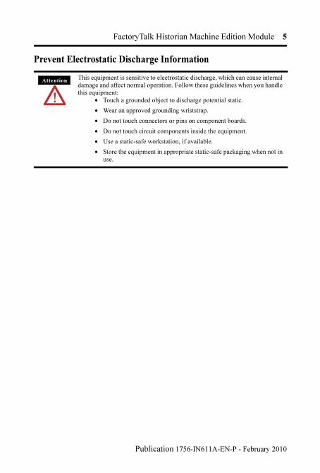
Prevent Electrostatic Discharge Information
AttentionThis equipment is sensitive to electrostatic discharge, which can cause internal damage and affect normal operation. Follow these guidelines when you handle this equipment:
• Touch a grounded object to discharge potential static.
• Wear an approved grounding wriststrap.
• Do not touch connectors or pins on component boards.
• Do not touch circuit components inside the equipment.
• Use a static-safe workstation, if available.
• Store the equipment in appropriate static-safe packaging when not in use.
Publication 1756-IN611A-EN-P - February 2010
6 FactoryTalk Historian Machine Edition Module
Removal and Insertion Under Power (RIUP) Capability
Ethernet Network Communications Connections
North American Hazardous Location Approval
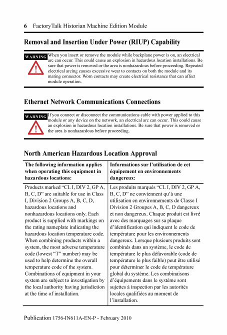
WARNINGWhen you insert or remove the module while backplane power is on, an electrical arc can occur. This could cause an explosion in hazardous location installations. Be sure that power is removed or the area is nonhazardous before proceeding. Repeated electrical arcing causes excessive wear to contacts on both the module and its mating connector. Worn contacts may create electrical resistance that can affect module operation.
WARNINGIf you connect or disconnect the communications cable with power applied to this module or any device on the network, an electrical arc can occur. This could cause an explosion in hazardous location installations. Be sure that power is removed or the area is nonhazardous before proceeding.
The following information applies
when operating this equipment in
hazardous locations:
Informations sur l’utilisation de cet
équipement en environnements
dangereux:
Products marked “CL I, DIV 2, GP A,
B, C, D” are suitable for use in Class
I, Division 2 Groups A, B, C, D,
hazardous locations and
nonhazardous locations only. Each
product is supplied with markings on
the rating nameplate indicating the
hazardous location temperature code.
When combining products within a
system, the most adverse temperature
code (lowest “T” number) may be
used to help determine the overall
temperature code of the system.
Combinations of equipment in your
system are subject to investigation by
the local authority having jurisdiction
at the time of installation.
Les produits marqués “CL I, DIV 2, GP A,
B, C, D” ne conviennent qu’à une
utilisation en environnements de Classe I
Division 2 Groupes A, B, C, D dangereux
et non dangereux. Chaque produit est livré
avec des marquages sur sa plaque
d’identification qui indiquent le code de
température pour les environnements
dangereux. Lorsque plusieurs produits sont
combinés dans un système, le code de
température le plus défavorable (code de
température le plus faible) peut être utilisé
pour déterminer le code de température
global du système. Les combinaisons
d’équipements dans le système sont
sujettes à inspection par les autorités
locales qualifiées au moment de
l’installation.
Publication 1756-IN611A-EN-P - February 2010

FactoryTalk Historian Machine Edition Module 7
WARNINGEXPLOSION
HAZARD
• Do not disconnect equipment unless power has been removed or the area is known to be nonhazardous.
• Do not disconnect connections to this equipment unless power has been removed or the area is known to be nonhazardous. Secure any external connections that mate to this equipment by using screws, sliding latches, threaded connectors, or other means provided with this product.
• Substitution of components may impair suitability for Class I, Division 2.
• If this product contains batteries, they must only be changed in an area known to be nonhazardous.
AVERTISSEMENT RISQUE D’EXPLOSION
• Couper le courant ou s’assurer que l’environnement est classé non dangereux avant de débrancher l'équipement.
• Couper le courant ou s'assurer que l’environnement est classé non dangereux avant de débrancher les connecteurs. Fixer tous les connecteurs externes reliés à cet équipement à l'aide de vis, loquets coulissants, connecteurs filetés ou autres moyens fournis avec ce produit.
• La substitution de composants peut rendre cet équipement inadapté à une utilisation en environnement de Classe I, Division 2.
• S’assurer que l’environnement est classé non dangereux avant de changer les piles.
The following information applies
when operating this equipment in
hazardous locations:
Informations sur l’utilisation de cet
équipement en environnements
dangereux:
Publication 1756-IN611A-EN-P - February 2010
8 FactoryTalk Historian Machine Edition Module
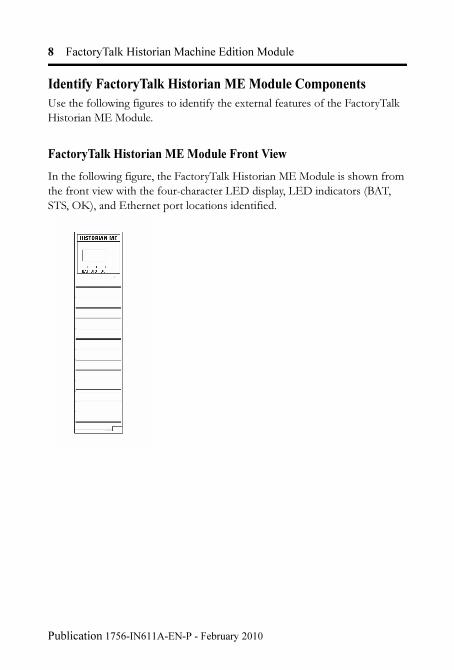
Identify FactoryTalk Historian ME Module Components
Use the following figures to identify the external features of the FactoryTalk
Historian ME Module.
FactoryTalk Historian ME Module Front View
In the following figure, the FactoryTalk Historian ME Module is shown from
the front view with the four-character LED display, LED indicators (BAT,
STS, OK), and Ethernet port locations identified.
Publication 1756-IN611A-EN-P - February 2010
FactoryTalk Historian Machine Edition Module 9
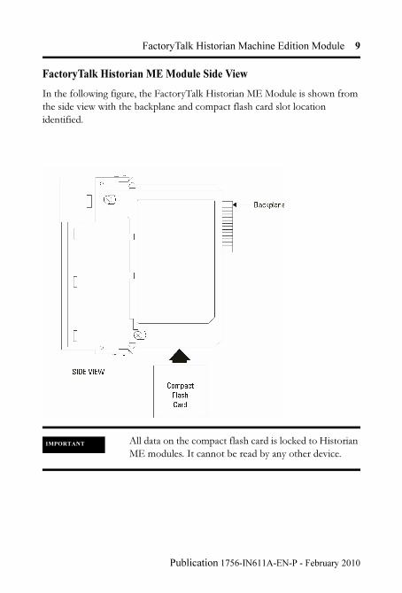
FactoryTalk Historian ME Module Side View
In the following figure, the FactoryTalk Historian ME Module is shown from
the side view with the backplane and compact flash card slot location
identified.
IMPORTANT All data on the compact flash card is locked to Historian
ME modules. It cannot be read by any other device.
Publication 1756-IN611A-EN-P - February 2010
10 FactoryTalk Historian Machine Edition Module
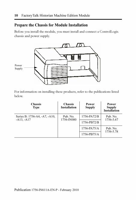
Prepare the Chassis for Module Installation
Before you install the module, you must install and connect a ControlLogix
chassis and power supply.
For information on installing these products, refer to the publications listed
below.
ChassisType
Chassis Installation
PowerSupply
Power Supply
Installation
Series B: 1756-A4, -A7, -A10, -A13, -A17
Pub. No. 1756-IN080
1756-PA72/B Pub. No. 1756-5.67
1756-PB72/B
1756-PA75/A Pub. No. 1756-5.78
1756-PB75/A
Power Supply
Publication 1756-IN611A-EN-P - February 2010
FactoryTalk Historian Machine Edition Module 11
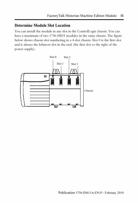
Determine Module Slot Location
You can install the module in any slot in the ControlLogix chassis. You can
have a maximum of two 1756-HIST modules in the same chassis. The figure
below shows chassis slot numbering in a 4-slot chassis. Slot 0 is the first slot
and is always the leftmost slot in the rack (the first slot to the right of the
power supply).
Slot 0
Slot 1
Slot 2
Slot 3
Chassis
Publication 1756-IN611A-EN-P - February 2010
12 FactoryTalk Historian Machine Edition Module
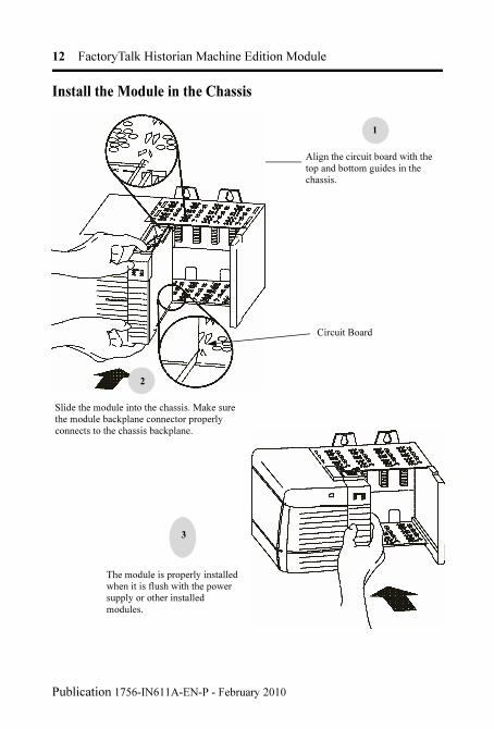
Install the Module in the Chassis
1
Slide the module into the chassis. Make sure the module backplane connector properly connects to the chassis backplane.
2
The module is properly installed when it is flush with the power supply or other installed modules.
Circuit Board
3
Align the circuit board with the top and bottom guides in the chassis.
Publication 1756-IN611A-EN-P - February 2010

FactoryTalk Historian Machine Edition Module 13
Remove or Replace the Module (when applicable)
IMPORTANT If you are replacing an existing module with an identical
one, and you want to resume identical system operation,
you must install the new module in the same slot.
Push on the upper and lower module tabs to disengage them.
1
Slide the module out of the chassis.
2
Publication 1756-IN611A-EN-P - February 2010

14 FactoryTalk Historian Machine Edition Module
Install or Remove the Module Under Power
This module is designed to be installed or removed while chassis power is
applied. Rockwell Automation recommends that you stop all data collection
services before you remove the module.
Wire the Ethernet Connector
Use an RJ45 connector to connect to the Ethernet. Wire the connector
according to the following illustration:
WARNINGWhen you insert or remove a module while backplane power is on, an electrical arc may occur. An electrical arc can cause personal injury or property damage by:
• sending an erroneous signal to your system’s field device causing unintended machine motion or loss of process control.
• causing an explosion in a hazardous environment.
Repeated electrical arcing causes excessive wear to contacts on both the module and its mating connector. Worn contacts may create electrical resistance that can affect module operation.
RJ 45
8
1
8 ------ NC
7 ------ NC
6 ------ RD-
5 ------ NC
4 ------ NC
3 ------ RD+
2 ------ TD-
1 ------ TD+
Publication 1756-IN611A-EN-P - February 2010
FactoryTalk Historian Machine Edition Module 15
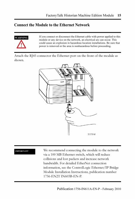
Connect the Module to the Ethernet Network
Attach the RJ45 connector the Ethernet port on the front of the module as
shown.
WARNINGIf you connect or disconnect the Ethernet cable with power applied to this module or any device on the network, an electrical arc can occur. This could cause an explosion in hazardous location installations. Be sure that power is removed or the area is nonhazardous before proceeding.
IMPORTANT We recommend connecting the module to the network
via a 100 MB Ethernet switch, which will reduce
collisions and lost packets and increase network
bandwidth. For detailed EtherNet connection
information, see the ControlLogic Ethernet/IP Bridge
Module Installation Instructions, publication number
1756-EN2T IN603B-EN-P.
Publication 1756-IN611A-EN-P - February 2010
16 FactoryTalk Historian Machine Edition Module
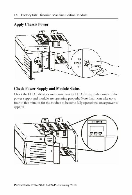
Apply Chassis Power
Check Power Supply and Module Status
Check the LED indicators and four-character LED display to determine if the
power supply and module are operating properly. Note that it can take up to
four to five minutes for the module to become fully operational once power is
applied.
Publication 1756-IN611A-EN-P - February 2010
FactoryTalk Historian Machine Edition Module 17
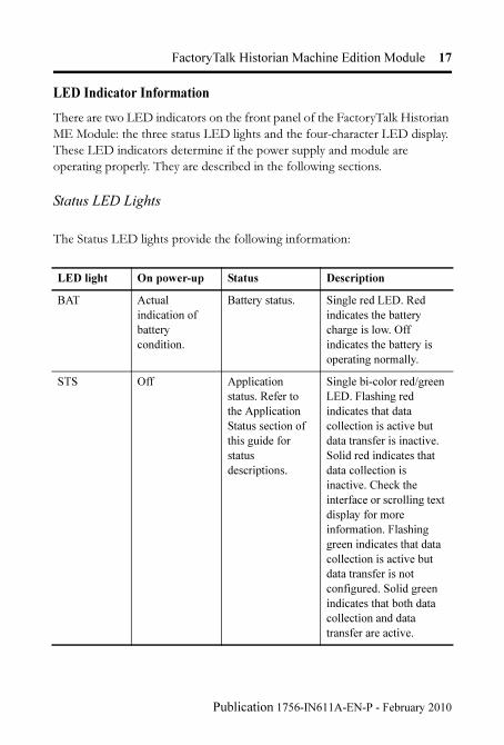
LED Indicator Information
There are two LED indicators on the front panel of the FactoryTalk Historian
ME Module: the three status LED lights and the four-character LED display.
These LED indicators determine if the power supply and module are
operating properly. They are described in the following sections.
Status LED Lights
The Status LED lights provide the following information:
LED light On power-up Status Description
BAT Actual
indication of
battery
condition.
Battery status. Single red LED. Red
indicates the battery
charge is low. Off
indicates the battery is
operating normally.
STS Off Application
status. Refer to
the Application
Status section of
this guide for
status
descriptions.
Single bi-color red/green
LED. Flashing red
indicates that data
collection is active but
data transfer is inactive.
Solid red indicates that
data collection is
inactive. Check the
interface or scrolling text
display for more
information. Flashing
green indicates that data
collection is active but
data transfer is not
configured. Solid green
indicates that both data
collection and data
transfer are active.
Publication 1756-IN611A-EN-P - February 2010
18 FactoryTalk Historian Machine Edition Module
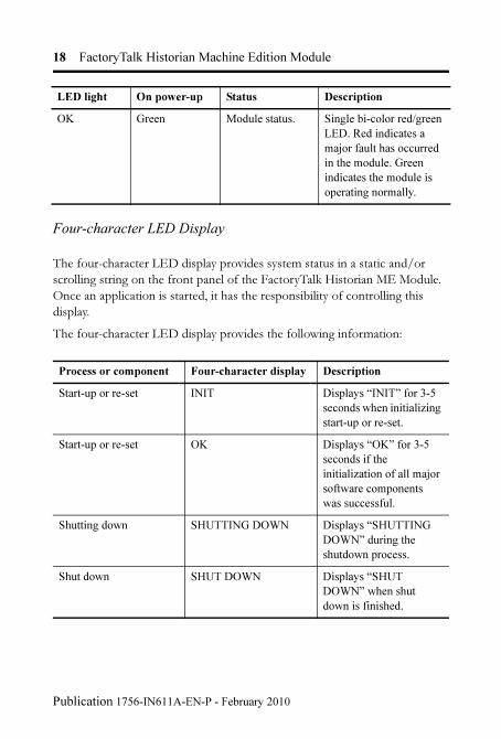
Four-character LED Display
The four-character LED display provides system status in a static and/or
scrolling string on the front panel of the FactoryTalk Historian ME Module.
Once an application is started, it has the responsibility of controlling this
display.
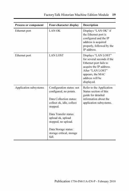
The four-character LED display provides the following information:
OK Green Module status. Single bi-color red/green
LED. Red indicates a
major fault has occurred
in the module. Green
indicates the module is
operating normally.
Process or component Four-character display Description
Start-up or re-set INIT Displays “INIT” for 3-5
seconds when initializing
start-up or re-set.
Start-up or re-set OK Displays “OK” for 3-5
seconds if the
initialization of all major
software components
was successful.
Shutting down SHUTTING DOWN Displays “SHUTTING
DOWN” during the
shutdown process.
Shut down SHUT DOWN Displays “SHUT
DOWN” when shut
down is finished.
LED light On power-up Status Description
Publication 1756-IN611A-EN-P - February 2010
FactoryTalk Historian Machine Edition Module 19
Ethernet port LAN OK Displays “LAN OK” if
the Ethernet port is
configured and the IP
address is acquired
properly, followed by the
IP address.
Ethernet port LAN LOST Displays “LAN LOST”
for several seconds if the
Ethernet port fails to
acquire the IP address.
After “LAN LOST”
appears, the MAC
address will be
displayed.
Application subsystems Configuration status: not
configured, no points.
Data Collection status:
collect ok, idle, collect
stopped.
Data Transfer status:
upload ok, upload
stopped, no upload.
Data Storage status:
storage critical, storage
full.
Refer to the Application
Status section of this
guide for detailed
information about the
application subsystems.
Process or component Four-character display Description
Publication 1756-IN611A-EN-P - February 2010
20 FactoryTalk Historian Machine Edition Module
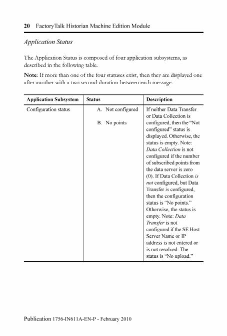
Application Status
The Application Status is composed of four application subsystems, as
described in the following table.
Note: If more than one of the four statuses exist, then they are displayed one
after another with a two second duration between each message.
Application Subsystem Status Description
Configuration status A. Not configured
B. No points
If neither Data Transfer
or Data Collection is
configured, then the “Not
configured” status is
displayed. Otherwise, the
status is empty. Note:
Data Collection is not
configured if the number
of subscribed points from
the data server is zero
(0). If Data Collection is
not configured, but Data
Transfer is configured,
then the configuration
status is “No points.”
Otherwise, the status is
empty. Note: Data
Transfer is not
configured if the SE Host
Server Name or IP
address is not entered or
is not resolved. The
status is “No upload.”
Publication 1756-IN611A-EN-P - February 2010

FactoryTalk Historian Machine Edition Module 21
Data collection status A. collect ok
B. collect stopped
If Data Collection is
active and properly
configured, then the
“collect ok.” If Data
Collection is configured
but not active, then the
“collect stopped” status
is displayed.
Data transfer status A. upload ok
B. upload stopped
If Data Transfer is active
and configured, then the
Data Transfer status is
“upload ok.” If Data
Transfer is configured
but not active, and the
Data Collection status is
not “idle,” then the Data
Transfer status is “upload
stopped.” Otherwise, the
Data Transfer status is
empty.
Data storage status A. storage critical
B. storage full
If Data Storage reaches
50% capacity (default
value for the first
threshold), then the Data
Storage status is “storage
critical.” If Data Storage
reaches 75% capacity
(default value for the
second threshold), then
the Data Storage status is
“storage full.” Otherwise,
the status is empty.
Application Subsystem Status Description
Publication 1756-IN611A-EN-P - February 2010
22 FactoryTalk Historian Machine Edition Module
Port (Ethernet) LED Information
The Port (Ethernet) LED on the 10/100 BASET connector supports IEEE
802.3, has a green LED for link activity, and an amber LED for 10/100 link
speed indication.
Where to Find Information on Configuring the Module
To configure your module, refer to the FactoryTalk Historian ME User’s
Guide, publication number 1756-UM611A, available on the FactoryTalk
Historian ME Installation CD and online at
www.rockwellautomation.com/literature.
How to Upgrade and Reinstall the Firmware
To upgrade the FactoryTalk Historian ME firmware (or reinstall it in case it
becomes corrupted), you must use the ControlFLASH Firmware upgrade kit.
Before you upgrade, please back up your log files by going to the Web
Diagnostics interface > Firmware > Upload Logs. Please see the FactoryTalk
Historian ME User's Guide for more information. For instructions on how to
perform the upgrade, please refer to the ControlFLASH Firmware Upgrade
Kit Quick Start Guide, publication number 1756-QS105C-EN-E. Before you
perform the upgrade, collect the following information, as you will need it
during the upgrade:
– The catalog number of the FactoryTalk Historian ME Module. This is
either 1756-HIST1G or 1756-HIST2G, depending on the size of the
compact flash drive.
– The network configuration information.
– The network path to the FactoryTalk Historian ME Module.
Publication 1756-IN611A-EN-P - February 2010
FactoryTalk Historian Machine Edition Module 23
– The firmware version number, which is listed on the FactoryTalk
Historian ME Module’s home page.
IMPORTANT Any kind of firmware upgrade or reinstall will clear out
all logs. A firmware upgrade will preseve archived data
and application configuration information, but a reinstall
will clear out all application configuration information
and archived data. If you want to save your settings,
therefore, download and back up your configuration and
logs. For more information, refer to the FactoryTalk
Historian ME user’s guide chapter on module
administration.
Publication 1756-IN611A-EN-P - February 2010
24 FactoryTalk Historian Machine Edition Module
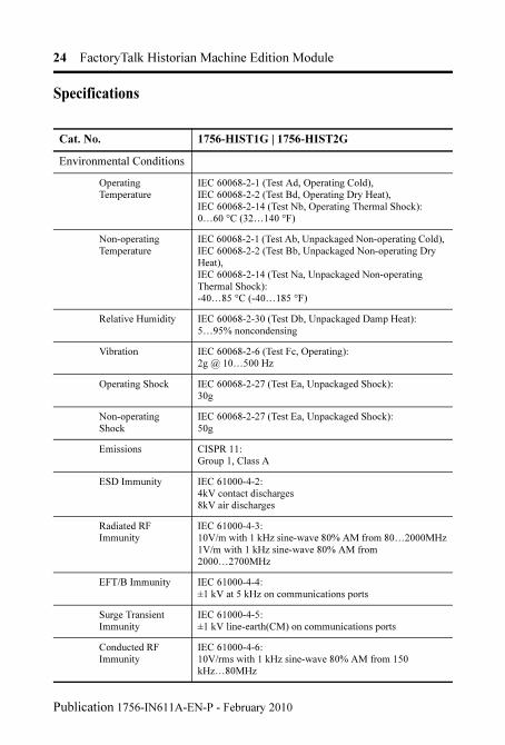
Specifications
Cat. No. 1756-HIST1G | 1756-HIST2G
Environmental Conditions
Operating Temperature
IEC 60068-2-1 (Test Ad, Operating Cold),IEC 60068-2-2 (Test Bd, Operating Dry Heat), IEC 60068-2-14 (Test Nb, Operating Thermal Shock):0…60 °C (32…140 °F)
Non-operating Temperature
IEC 60068-2-1 (Test Ab, Unpackaged Non-operating Cold), IEC 60068-2-2 (Test Bb, Unpackaged Non-operating Dry Heat), IEC 60068-2-14 (Test Na, Unpackaged Non-operating Thermal Shock): -40…85 °C (-40…185 °F)
Relative Humidity IEC 60068-2-30 (Test Db, Unpackaged Damp Heat): 5…95% noncondensing
Vibration IEC 60068-2-6 (Test Fc, Operating):2g @ 10…500 Hz
Operating Shock IEC 60068-2-27 (Test Ea, Unpackaged Shock):30g
Non-operating Shock
IEC 60068-2-27 (Test Ea, Unpackaged Shock): 50g
Emissions CISPR 11: Group 1, Class A
ESD Immunity IEC 61000-4-2: 4kV contact discharges8kV air discharges
Radiated RF Immunity
IEC 61000-4-3:10V/m with 1 kHz sine-wave 80% AM from 80…2000MHz1V/m with 1 kHz sine-wave 80% AM from 2000…2700MHz
EFT/B Immunity IEC 61000-4-4:±1 kV at 5 kHz on communications ports
Surge Transient Immunity
IEC 61000-4-5:±1 kV line-earth(CM) on communications ports
Conducted RF Immunity
IEC 61000-4-6:10V/rms with 1 kHz sine-wave 80% AM from 150 kHz…80MHz
Publication 1756-IN611A-EN-P - February 2010
FactoryTalk Historian Machine Edition Module 25
Allen-Bradley and ControlLogix are trademarks of Rockwell Automation.
Ethernet is a trademark of Digital Equipment Corporation, Intel, and Xerox Corporation.
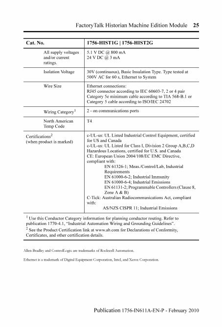
All supply voltages and/or current ratings.
5.1 V DC @ 800 mA24 V DC @ 3 mA
Isolation Voltage 30V (continuous), Basic Insulation Type. Type tested at 500V AC for 60 s, Ethernet to System
Wire Size Ethernet connections:RJ45 connector according to IEC 60603-7, 2 or 4 pair Category 5e minimum cable according to TIA 568-B.1 or Category 5 cable according to ISO/IEC 24702
Wiring Category1 2 - on communications ports
North American Temp Code
T4
Certifications2
(when product is marked)
c-UL-us: UL Listed Industrial Control Equipment, certified for US and Canadac-UL-us: UL Listed for Class I, Division 2 Group A,B,C,D Hazardous Locations, certified for U.S. and CanadaCE: European Union 2004/108/EC EMC Directive, compliant with:
EN 61326-1; Meas./Control/Lab, Industrial RequirementsEN 61000-6-2; Industrial ImmunityEN 61000-6-4; Industrial EmissionsEN 61131-2; Programmable Controllers (Clause 8, Zone A & B)
C-Tick: Australian Radiocommunications Act, compliant with: AS/NZS CISPR 11; Industrial Emissions
1 Use this Conductor Category information for planning conductor routing. Refer to publication 1770-4.1, “Industrial Automation Wiring and Grounding Guidelines”.2 See the Product Certification link at www.ab.com for Declarations of Conformity, Certificates, and other certification details.
Cat. No. 1756-HIST1G | 1756-HIST2G
Publication 1756-IN611A-EN-P - February 2010

Rockwell Automation Support
Rockwell Automation provides technical information on the web to assist you in using
its products. At http://support.rockwellautomation.com, you can find technical
manuals, a knowledge base of FAQs, technical and application notes, sample code and
links to software service packs, and a MySupport feature that you can customize to
make the best use of these tools.
For an additional level of technical phone support for installation, configuration and
troubleshooting, we offer TechConnect Support programs. For more information,
contact your local distributor or Rockwell Automation representative, or visit
http://support.rockwellautomation.com.
Installation Assistance
If you experience a problem with a hardware module, please review the information
that's contained in this manual. You can also contact a special Customer Support
number for initial help in getting your module up and running:
New Product Satisfaction Return
Rockwell tests all of its products to ensure that they are fully operational when shipped
from the manufacturing facility. However, if your product is not functioning and needs
to be returned:
www.rockwellautomation.com
Corporate Headquarters
Rockwell Automation, 777 East Wisconsin Avenue, Suite 1400, Milwaukee, WI, 53202-5302 USA, Tel: (1) 414.212.5200, Fax: (1) 414.212.5201
Headquarters for Allen-Bradley Products, Rockwell Software Products and Global Manufacturing Solutions
Americas: Rockwell Automation, 1201 South Second Street, Milwaukee, WI 53204-2496 USA , Tel: (1) 414.382.2000, Fax: (1) 414.382.4444
Europe/Middle East/Africa: Rockwell Automation SA/NV, Vorstlaan/Boulevard du Souverain 36, 1170 Brussels, Belgium, Tel: (32) 2 663 0600, Fax (32) 2 663 0640
Asia Pacific: Rockwell Automation, Level 14, Core F, Cyberport 3, 100 Cyberport Road, Hong Kong, Tel: (852) 2887 4788, Fax: (852) 2508 1846
United States 1.440.646.3223 Monday – Friday, 8am – 5pm EST
Outside United States Please contact your local Rockwell Automation representative for any technical support issues.
United States Contact your distributor. You must provide a Customer Support case number (see phone number above to obtain one) to your distributor in order to complete the return process.
Outside United States Please contact your local Rockwell Automation representative for return procedure.
Publication 1756-IN611A-EN-P - February 2010 PN-58128
Copyright © 2010 Rockwell Automation, Inc. All rights reserved. Printed in the U.S.A.