facility inspection report - ippe.comfacility inspection report. 60 kmta caprolactam facility ....
TRANSCRIPT
IPP Confidential
Facility Inspection Report
60 kmta Caprolactam Facility
Prepared by: International Process Plants Hamilton Business Center 17A Marlen Drive Hamilton, NJ 08691
2
IPP Confidential
60 kmta Caprolactam Facility
Executive Summary This Caprolactam Facility includes all intermediate and byproduct plants. The facility starts with benzene and finishes with caprolactam and ammonium sulfate byproduct:
• Cyclohexane Plant – 80 kmta • Cyclohexanone Plant – 55 kmta • Oximation Plant – 62 kmta • Caprolactam Plant – 60 kmta
• Ammonium Sulfate – 108 kmta • Incinerator – 5 m3/hr liquid
waste
The facility had some upgrades over the years. The majority of the site shut down in 2009, but the cyclohexane unit ran until August 2013. Documentation is complete and well-organized. Much of it is electronic and has already been shared with IPP. The facility received ISO-9001 certification in 1997 and ISO-14001 certification in 2004. DCS is by Yokogawa (Centum CS-3000) and is used in the Oximation, Caprolactam, Ammonia Sulfate, and Incinerator units. The plant has been well-maintained and is still being kept up with a staff of four employees. There is a nitrogen pad on the process and they are turning the rotating equipment monthly. There are abundant spare parts available with the facility. Transportation to and from the facility by road is excellent and it is 24 km to the nearest major port.
3
IPP Confidential
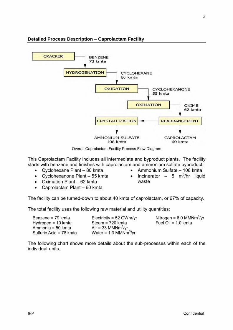
Detailed Process Description – Caprolactam Facility
Overall Caprolactam Facility Process Flow Diagram
This Caprolactam Facility includes all intermediate and byproduct plants. The facility starts with benzene and finishes with caprolactam and ammonium sulfate byproduct:
• Cyclohexane Plant – 80 kmta • Cyclohexanone Plant – 55 kmta • Oximation Plant – 62 kmta • Caprolactam Plant – 60 kmta
• Ammonium Sulfate – 108 kmta • Incinerator – 5 m3/hr liquid
waste
The facility can be turned-down to about 40 kmta of caprolactam, or 67% of capacity. The total facility uses the following raw material and utility quantities: Benzene = 79 kmta Hydrogen = 10 kmta Ammonia = 50 kmta Sulfuric Acid = 78 kmta
Electricity = 52 GWhr/yr Steam = 720 kmta Air = 33 MMNm3/yr Water = 1.3 MMNm3/yr
Nitrogen = 6.0 MMNm3/yr Fuel Oil = 1.0 kmta
The following chart shows more details about the sub-processes within each of the individual units.
4
IPP Confidential
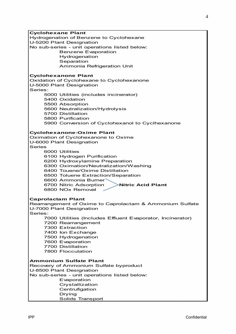
Cyclohexane PlantHydrogenation of Benzene to CyclohexaneU-5200 Plant DesignationNo sub-series - unit operations listed below:
Benzene EvaporationHydrogenationSeparationAmmonia Refrigeration Unit
Cyclohexanone PlantOxidation of Cyclohexane to CyclohexanoneU-5000 Plant DesignationSeries:
5000 Utilities (includes incinerator)5400 Oxidation5500 Absorption5600 Neutralization/Hydrolysis5700 Distillation5800 Purification5900 Conversion of Cyclohexanol to Cyclhexanone
Cyclohexanone-Oxime PlantOximation of Cyclohexanone to OximeU-6000 Plant DesignationSeries
6000 Utilities6100 Hydrogen Purification6200 Hydroxylamine Preparation6300 Oximation/Neutralization/Washing6400 Touene/Oxime Distillation6500 Toluene Extraction/Separation6600 Ammonia Burner6700 Nitric Adsorption Nitric Acid Plant6800 NOx Removal
Caprolactam PlantRearrangement of Oxime to Caprolactam & Ammonium SulfateU-7000 Plant DesignationSeries:
7000 Utilities (Includes Effluent Evaporator, Incinerator)7200 Rearrangement7300 Extraction7400 Ion Exchange7500 Hydrogenation7600 Evaporation7700 Distillation7800 Flocculation
Ammonium Sulfate PlantRecovery of Ammonium Sulfate byproductU-8500 Plant DesignationNo sub-series - unit operations listed below:
EvaporationCrystallizationCentrufigationDryingSolids Transport
5
IPP Confidential
Detailed Process Description – Cyclohexane Facility
Cyclohexane Plant
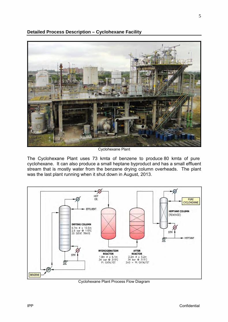
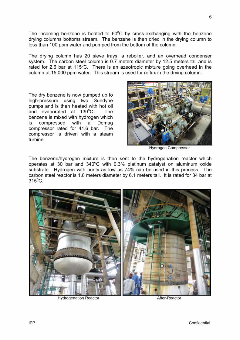
The Cyclohexane Plant uses 73 kmta of benzene to produce 80 kmta of pure cyclohexane. It can also produce a small heptane byproduct and has a small effluent stream that is mostly water from the benzene drying column overheads. The plant was the last plant running when it shut down in August, 2013.
Cyclohexane Plant Process Flow Diagram
6
IPP Confidential
The incoming benzene is heated to 60oC by cross-exchanging with the benzene drying columns bottoms stream. The benzene is then dried in the drying column to less than 100 ppm water and pumped from the bottom of the column. The drying column has 20 sieve trays, a reboiler, and an overhead condenser system. The carbon steel column is 0.7 meters diameter by 12.5 meters tall and is rated for 2.6 bar at 115oC. There is an azeotropic mixture going overhead in the column at 15,000 ppm water. This stream is used for reflux in the drying column. The dry benzene is now pumped up to high-pressure using two Sundyne pumps and is then heated with hot oil and evaporated at 130oC. The benzene is mixed with hydrogen which is compressed with a Demag compressor rated for 41.6 bar. The compressor is driven with a steam turbine.
Hydrogen Compressor
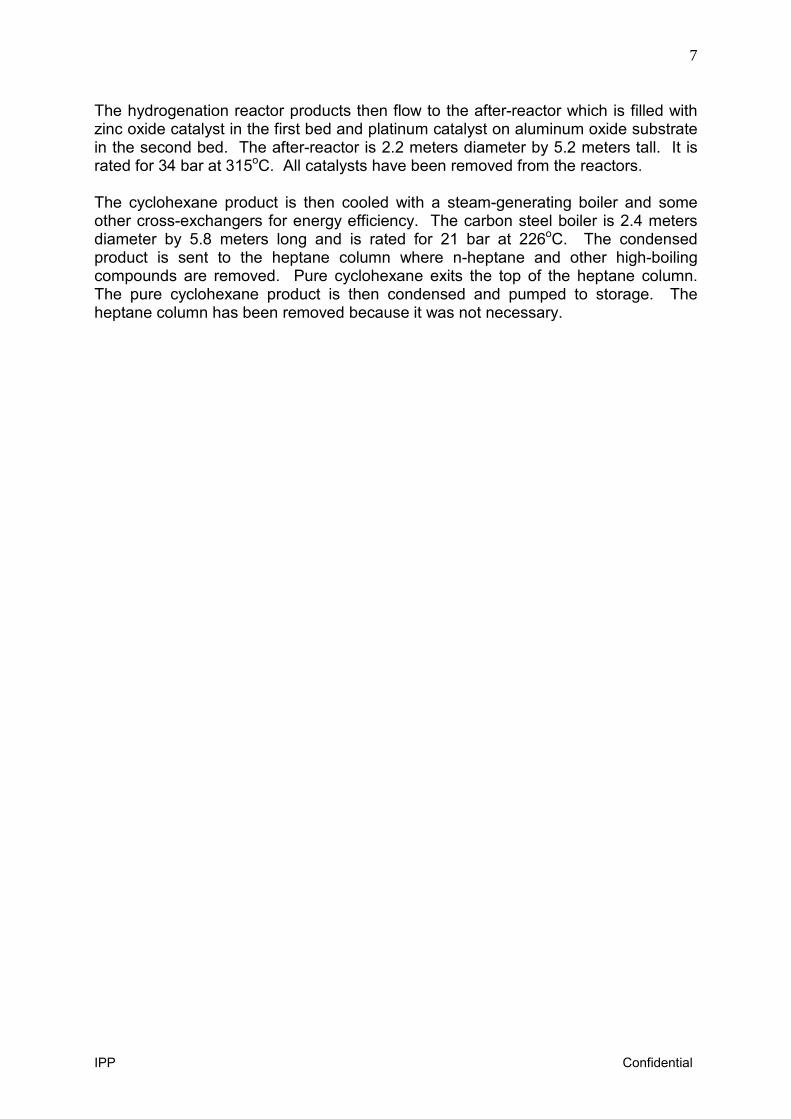
The benzene/hydrogen mixture is then sent to the hydrogenation reactor which operates at 30 bar and 340oC with 0.3% platinum catalyst on aluminum oxide substrate. Hydrogen with purity as low as 74% can be used in this process. The carbon steel reactor is 1.8 meters diameter by 6.1 meters tall. It is rated for 34 bar at 315oC.
Hydrogenation Reactor After-Reactor
7
IPP Confidential
The hydrogenation reactor products then flow to the after-reactor which is filled with zinc oxide catalyst in the first bed and platinum catalyst on aluminum oxide substrate in the second bed. The after-reactor is 2.2 meters diameter by 5.2 meters tall. It is rated for 34 bar at 315oC. All catalysts have been removed from the reactors. The cyclohexane product is then cooled with a steam-generating boiler and some other cross-exchangers for energy efficiency. The carbon steel boiler is 2.4 meters diameter by 5.8 meters long and is rated for 21 bar at 226oC. The condensed product is sent to the heptane column where n-heptane and other high-boiling compounds are removed. Pure cyclohexane exits the top of the heptane column. The pure cyclohexane product is then condensed and pumped to storage. The heptane column has been removed because it was not necessary.
8
IPP Confidential
Detailed Process Description – Cyclohexanone Plant
Cyclohexanone Plant Process Flow Diagram
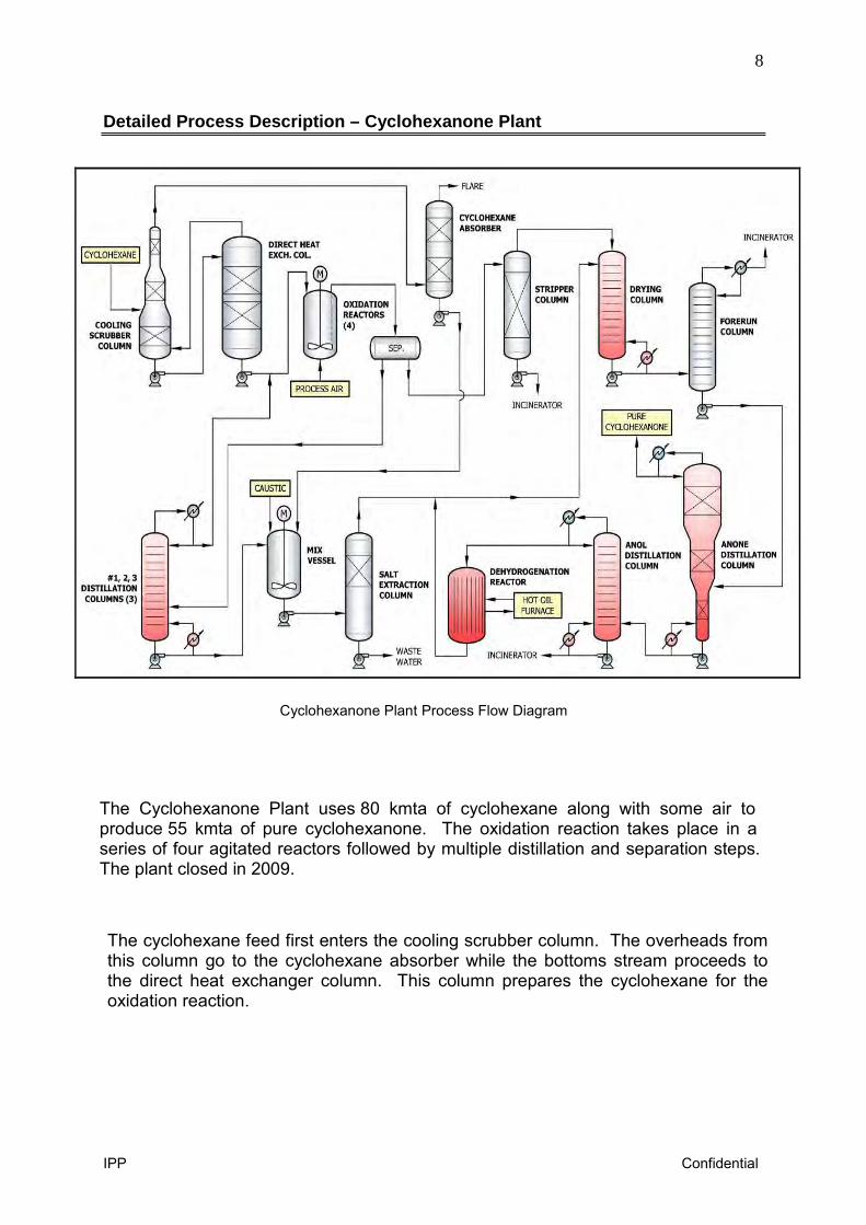
The Cyclohexanone Plant uses 80 kmta of cyclohexane along with some air to produce 55 kmta of pure cyclohexanone. The oxidation reaction takes place in a series of four agitated reactors followed by multiple distillation and separation steps. The plant closed in 2009.
The cyclohexane feed first enters the cooling scrubber column. The overheads from this column go to the cyclohexane absorber while the bottoms stream proceeds to the direct heat exchanger column. This column prepares the cyclohexane for the oxidation reaction.
9
IPP Confidential
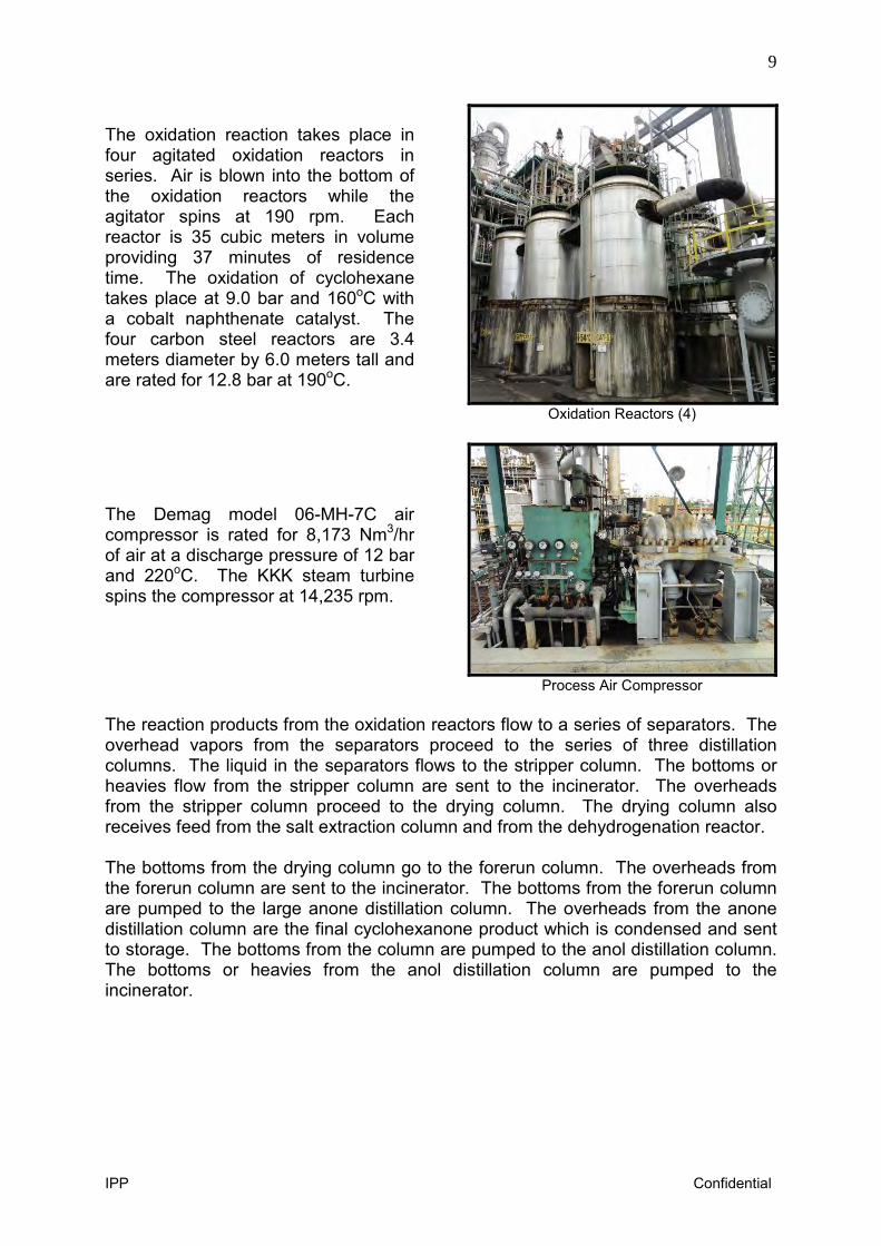
The oxidation reaction takes place in four agitated oxidation reactors in series. Air is blown into the bottom of the oxidation reactors while the agitator spins at 190 rpm. Each reactor is 35 cubic meters in volume providing 37 minutes of residence time. The oxidation of cyclohexane takes place at 9.0 bar and 160oC with a cobalt naphthenate catalyst. The four carbon steel reactors are 3.4 meters diameter by 6.0 meters tall and are rated for 12.8 bar at 190oC.
Oxidation Reactors (4)
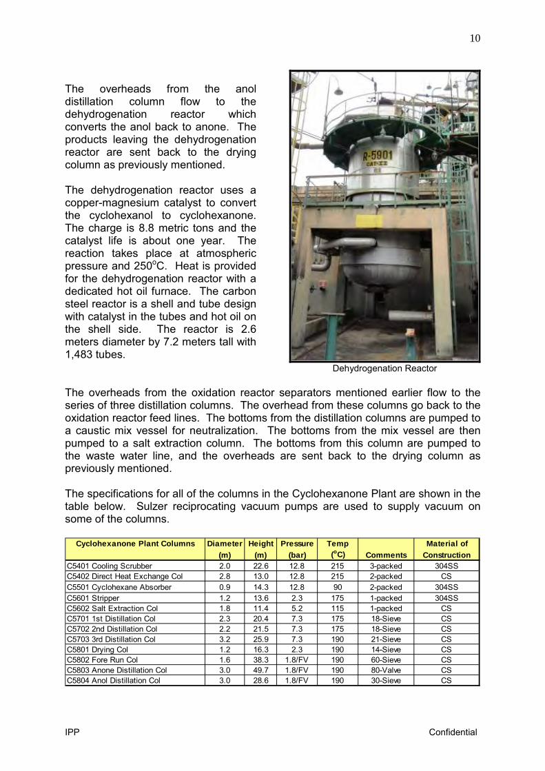
The Demag model 06-MH-7C air compressor is rated for 8,173 Nm3/hr of air at a discharge pressure of 12 bar and 220oC. The KKK steam turbine spins the compressor at 14,235 rpm.
Process Air Compressor
The reaction products from the oxidation reactors flow to a series of separators. The overhead vapors from the separators proceed to the series of three distillation columns. The liquid in the separators flows to the stripper column. The bottoms or heavies flow from the stripper column are sent to the incinerator. The overheads from the stripper column proceed to the drying column. The drying column also receives feed from the salt extraction column and from the dehydrogenation reactor. The bottoms from the drying column go to the forerun column. The overheads from the forerun column are sent to the incinerator. The bottoms from the forerun column are pumped to the large anone distillation column. The overheads from the anone distillation column are the final cyclohexanone product which is condensed and sent to storage. The bottoms from the column are pumped to the anol distillation column. The bottoms or heavies from the anol distillation column are pumped to the incinerator.
10
IPP Confidential
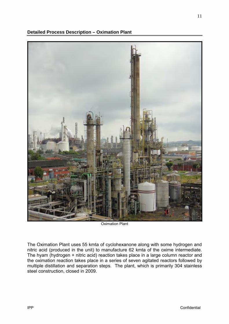
The overheads from the anol distillation column flow to the dehydrogenation reactor which converts the anol back to anone. The products leaving the dehydrogenation reactor are sent back to the drying column as previously mentioned. The dehydrogenation reactor uses a copper-magnesium catalyst to convert the cyclohexanol to cyclohexanone. The charge is 8.8 metric tons and the catalyst life is about one year. The reaction takes place at atmospheric pressure and 250oC. Heat is provided for the dehydrogenation reactor with a dedicated hot oil furnace. The carbon steel reactor is a shell and tube design with catalyst in the tubes and hot oil on the shell side. The reactor is 2.6 meters diameter by 7.2 meters tall with 1,483 tubes.
Dehydrogenation Reactor
The overheads from the oxidation reactor separators mentioned earlier flow to the series of three distillation columns. The overhead from these columns go back to the oxidation reactor feed lines. The bottoms from the distillation columns are pumped to a caustic mix vessel for neutralization. The bottoms from the mix vessel are then pumped to a salt extraction column. The bottoms from this column are pumped to the waste water line, and the overheads are sent back to the drying column as previously mentioned. The specifications for all of the columns in the Cyclohexanone Plant are shown in the table below. Sulzer reciprocating vacuum pumps are used to supply vacuum on some of the columns.
Cyclohexanone Plant Columns Diameter Height Pressure Temp Material of(m) (m) (bar) (oC) Comments Construction
C5401 Cooling Scrubber 2.0 22.6 12.8 215 3-packed 304SSC5402 Direct Heat Exchange Col 2.8 13.0 12.8 215 2-packed CSC5501 Cyclohexane Absorber 0.9 14.3 12.8 90 2-packed 304SSC5601 Stripper 1.2 13.6 2.3 175 1-packed 304SSC5602 Salt Extraction Col 1.8 11.4 5.2 115 1-packed CSC5701 1st Distillation Col 2.3 20.4 7.3 175 18-Sieve CSC5702 2nd Distillation Col 2.2 21.5 7.3 175 18-Sieve CSC5703 3rd Distillation Col 3.2 25.9 7.3 190 21-Sieve CSC5801 Drying Col 1.2 16.3 2.3 190 14-Sieve CSC5802 Fore Run Col 1.6 38.3 1.8/FV 190 60-Sieve CSC5803 Anone Distillation Col 3.0 49.7 1.8/FV 190 80-Valve CSC5804 Anol Distillation Col 3.0 28.6 1.8/FV 190 30-Sieve CS
11
IPP Confidential
Detailed Process Description – Oximation Plant
Oximation Plant
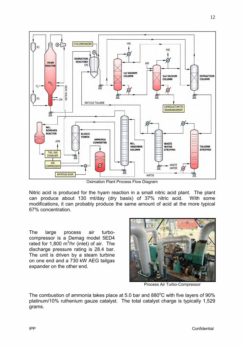
The Oximation Plant uses 55 kmta of cyclohexanone along with some hydrogen and nitric acid (produced in the unit) to manufacture 62 kmta of the oxime intermediate. The hyam (hydrogen + nitric acid) reaction takes place in a large column reactor and the oximation reaction takes place in a series of seven agitated reactors followed by multiple distillation and separation steps. The plant, which is primarily 304 stainless steel construction, closed in 2009.
12
IPP Confidential
Oximation Plant Process Flow Diagram
Nitric acid is produced for the hyam reaction in a small nitric acid plant. The plant can produce about 130 mt/day (dry basis) of 37% nitric acid. With some modifications, it can probably produce the same amount of acid at the more typical 67% concentration. The large process air turbo-compressor is a Demag model 5ED4 rated for 1,800 m3/hr (inlet) of air. The discharge pressure rating is 28.4 bar. The unit is driven by a steam turbine on one end and a 730 kW AEG tailgas expander on the other end.
Process Air Turbo-Compressor
The combustion of ammonia takes place at 5.0 bar and 880oC with five layers of 90% platinum/10% ruthenium gauze catalyst. The total catalyst charge is typically 1,529 grams.
13
IPP Confidential
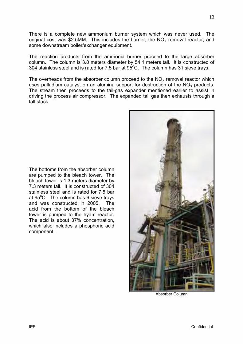
There is a complete new ammonium burner system which was never used. The original cost was $2.5MM. This includes the burner, the NOx removal reactor, and some downstream boiler/exchanger equipment. The reaction products from the ammonia burner proceed to the large absorber column. The column is 3.0 meters diameter by 54.1 meters tall. It is constructed of 304 stainless steel and is rated for 7.5 bar at 95oC. The column has 31 sieve trays. The overheads from the absorber column proceed to the NOx removal reactor which uses palladium catalyst on an alumina support for destruction of the NOx products. The stream then proceeds to the tail-gas expander mentioned earlier to assist in driving the process air compressor. The expanded tail gas then exhausts through a tall stack. The bottoms from the absorber column are pumped to the bleach tower. The bleach tower is 1.3 meters diameter by 7.3 meters tall. It is constructed of 304 stainless steel and is rated for 7.5 bar at 95oC. The column has 6 sieve trays and was constructed in 2005. The acid from the bottom of the bleach tower is pumped to the hyam reactor. The acid is about 37% concentration, which also includes a phosphoric acid component.
Absorber Column
14
IPP Confidential
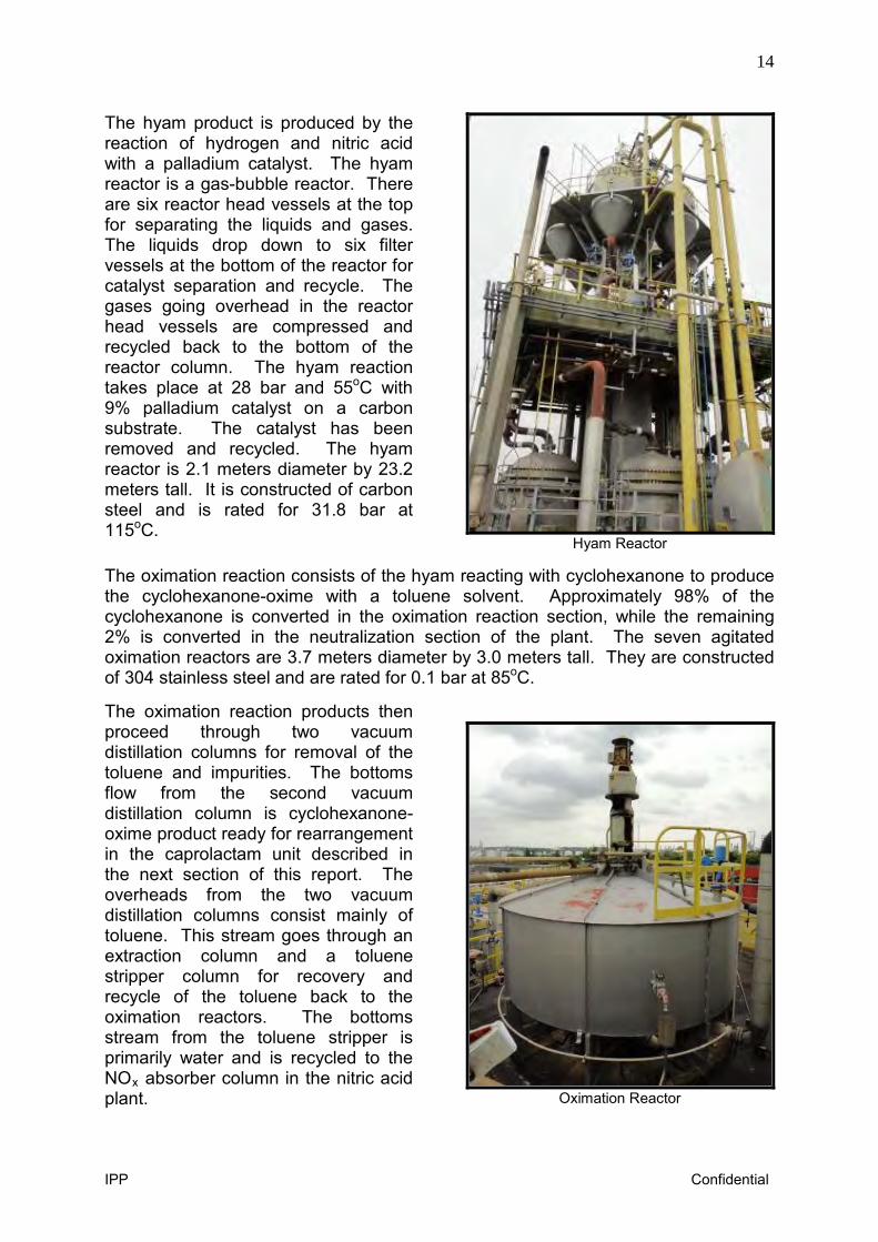
The hyam product is produced by the reaction of hydrogen and nitric acid with a palladium catalyst. The hyam reactor is a gas-bubble reactor. There are six reactor head vessels at the top for separating the liquids and gases. The liquids drop down to six filter vessels at the bottom of the reactor for catalyst separation and recycle. The gases going overhead in the reactor head vessels are compressed and recycled back to the bottom of the reactor column. The hyam reaction takes place at 28 bar and 55oC with 9% palladium catalyst on a carbon substrate. The catalyst has been removed and recycled. The hyam reactor is 2.1 meters diameter by 23.2 meters tall. It is constructed of carbon steel and is rated for 31.8 bar at 115oC.
Hyam Reactor The oximation reaction consists of the hyam reacting with cyclohexanone to produce the cyclohexanone-oxime with a toluene solvent. Approximately 98% of the cyclohexanone is converted in the oximation reaction section, while the remaining 2% is converted in the neutralization section of the plant. The seven agitated oximation reactors are 3.7 meters diameter by 3.0 meters tall. They are constructed of 304 stainless steel and are rated for 0.1 bar at 85oC. The oximation reaction products then proceed through two vacuum distillation columns for removal of the toluene and impurities. The bottoms flow from the second vacuum distillation column is cyclohexanone-oxime product ready for rearrangement in the caprolactam unit described in the next section of this report. The overheads from the two vacuum distillation columns consist mainly of toluene. This stream goes through an extraction column and a toluene stripper column for recovery and recycle of the toluene back to the oximation reactors. The bottoms stream from the toluene stripper is primarily water and is recycled to the NOx absorber column in the nitric acid plant.
Oximation Reactor
15
IPP Confidential
Detailed Process Description – Caprolactam Plant
Caprolactam Plant
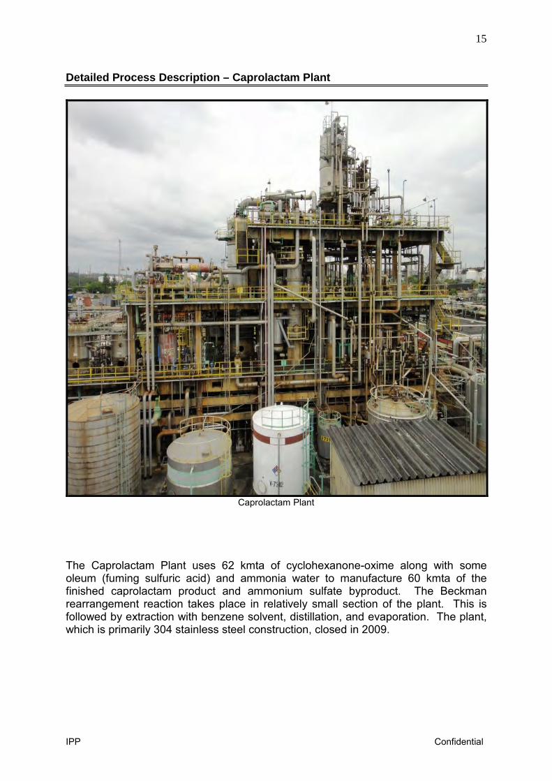
The Caprolactam Plant uses 62 kmta of cyclohexanone-oxime along with some oleum (fuming sulfuric acid) and ammonia water to manufacture 60 kmta of the finished caprolactam product and ammonium sulfate byproduct. The Beckman rearrangement reaction takes place in relatively small section of the plant. This is followed by extraction with benzene solvent, distillation, and evaporation. The plant, which is primarily 304 stainless steel construction, closed in 2009.
16
IPP Confidential
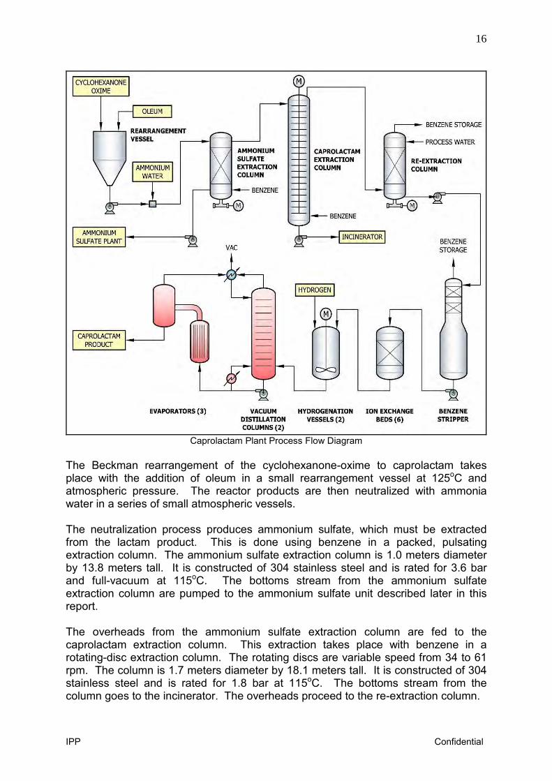
Caprolactam Plant Process Flow Diagram
The Beckman rearrangement of the cyclohexanone-oxime to caprolactam takes place with the addition of oleum in a small rearrangement vessel at 125oC and atmospheric pressure. The reactor products are then neutralized with ammonia water in a series of small atmospheric vessels. The neutralization process produces ammonium sulfate, which must be extracted from the lactam product. This is done using benzene in a packed, pulsating extraction column. The ammonium sulfate extraction column is 1.0 meters diameter by 13.8 meters tall. It is constructed of 304 stainless steel and is rated for 3.6 bar and full-vacuum at 115oC. The bottoms stream from the ammonium sulfate extraction column are pumped to the ammonium sulfate unit described later in this report. The overheads from the ammonium sulfate extraction column are fed to the caprolactam extraction column. This extraction takes place with benzene in a rotating-disc extraction column. The rotating discs are variable speed from 34 to 61 rpm. The column is 1.7 meters diameter by 18.1 meters tall. It is constructed of 304 stainless steel and is rated for 1.8 bar at 115oC. The bottoms stream from the column goes to the incinerator. The overheads proceed to the re-extraction column.
17
IPP Confidential
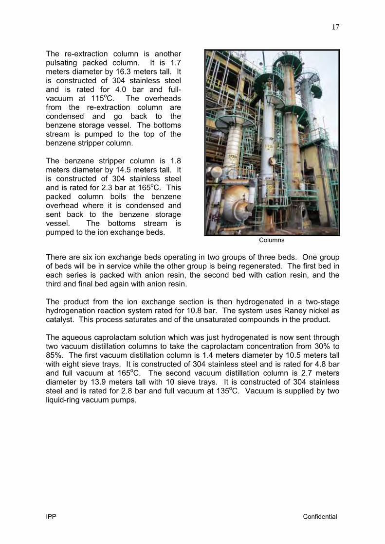
The re-extraction column is another pulsating packed column. It is 1.7 meters diameter by 16.3 meters tall. It is constructed of 304 stainless steel and is rated for 4.0 bar and full-vacuum at 115oC. The overheads from the re-extraction column are condensed and go back to the benzene storage vessel. The bottoms stream is pumped to the top of the benzene stripper column. The benzene stripper column is 1.8 meters diameter by 14.5 meters tall. It is constructed of 304 stainless steel and is rated for 2.3 bar at 165oC. This packed column boils the benzene overhead where it is condensed and sent back to the benzene storage vessel. The bottoms stream is pumped to the ion exchange beds.
Columns There are six ion exchange beds operating in two groups of three beds. One group of beds will be in service while the other group is being regenerated. The first bed in each series is packed with anion resin, the second bed with cation resin, and the third and final bed again with anion resin. The product from the ion exchange section is then hydrogenated in a two-stage hydrogenation reaction system rated for 10.8 bar. The system uses Raney nickel as catalyst. This process saturates and of the unsaturated compounds in the product. The aqueous caprolactam solution which was just hydrogenated is now sent through two vacuum distillation columns to take the caprolactam concentration from 30% to 85%. The first vacuum distillation column is 1.4 meters diameter by 10.5 meters tall with eight sieve trays. It is constructed of 304 stainless steel and is rated for 4.8 bar and full vacuum at 165oC. The second vacuum distillation column is 2.7 meters diameter by 13.9 meters tall with 10 sieve trays. It is constructed of 304 stainless steel and is rated for 2.8 bar and full vacuum at 135oC. Vacuum is supplied by two liquid-ring vacuum pumps.
18
IPP Confidential
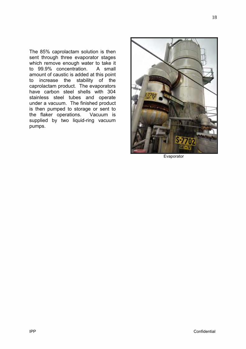
The 85% caprolactam solution is then sent through three evaporator stages which remove enough water to take it to 99.9% concentration. A small amount of caustic is added at this point to increase the stability of the caprolactam product. The evaporators have carbon steel shells with 304 stainless steel tubes and operate under a vacuum. The finished product is then pumped to storage or sent to the flaker operations. Vacuum is supplied by two liquid-ring vacuum pumps.
Evaporator
19
IPP Confidential
Detailed Process Description – Ammonium Sulfate Plant
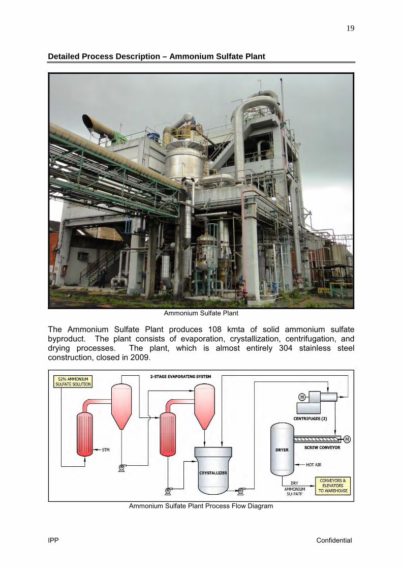
Ammonium Sulfate Plant
The Ammonium Sulfate Plant produces 108 kmta of solid ammonium sulfate byproduct. The plant consists of evaporation, crystallization, centrifugation, and drying processes. The plant, which is almost entirely 304 stainless steel construction, closed in 2009.
Ammonium Sulfate Plant Process Flow Diagram
20
IPP Confidential
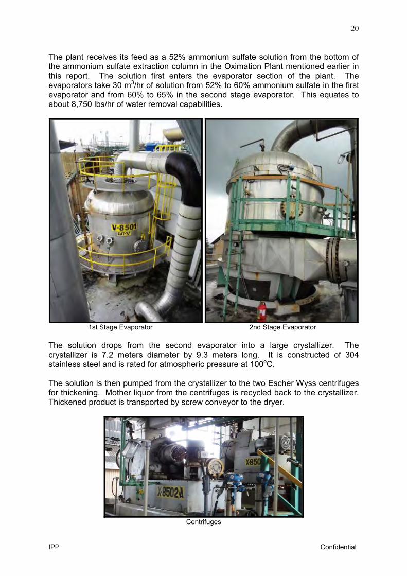
The plant receives its feed as a 52% ammonium sulfate solution from the bottom of the ammonium sulfate extraction column in the Oximation Plant mentioned earlier in this report. The solution first enters the evaporator section of the plant. The evaporators take 30 m3/hr of solution from 52% to 60% ammonium sulfate in the first evaporator and from 60% to 65% in the second stage evaporator. This equates to about 8,750 lbs/hr of water removal capabilities.
1st Stage Evaporator 2nd Stage Evaporator The solution drops from the second evaporator into a large crystallizer. The crystallizer is 7.2 meters diameter by 9.3 meters long. It is constructed of 304 stainless steel and is rated for atmospheric pressure at 100oC. The solution is then pumped from the crystallizer to the two Escher Wyss centrifuges for thickening. Mother liquor from the centrifuges is recycled back to the crystallizer. Thickened product is transported by screw conveyor to the dryer.
Centrifuges
21
IPP Confidential
The dryer is 2.3 meters diameter by 8.4 meters long. It is constructed of 304 stainless steel and is rated for 0.1 bar at 180oC. Air for the dryer is steam-heated with a large 304 stainless steel exchanger. The heater is 1.4 meters diameter by 4.0 meters long and is rated for 1.8 bar at 103oC. The dry ammonium sulfate discharges from the dryer onto a flat conveyor belt. The conveyor takes the product to a bucket elevator which transfers the product through some sieves and onto another conveyor belt going to the warehouse. The product dumps onto the large concrete warehouse floor and is moved with front-end loaders to desired warehouse locations.
22
IPP Confidential
Detailed Process Description – Incinerator Unit
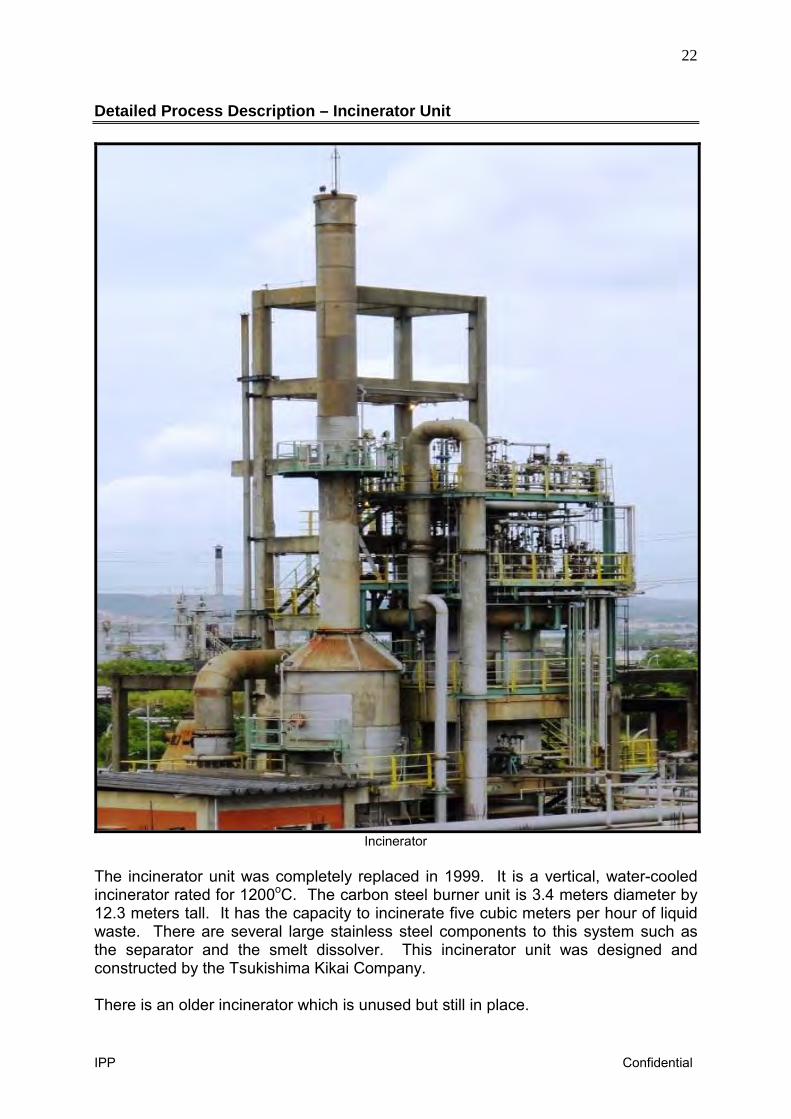
Incinerator
The incinerator unit was completely replaced in 1999. It is a vertical, water-cooled incinerator rated for 1200oC. The carbon steel burner unit is 3.4 meters diameter by 12.3 meters tall. It has the capacity to incinerate five cubic meters per hour of liquid waste. There are several large stainless steel components to this system such as the separator and the smelt dissolver. This incinerator unit was designed and constructed by the Tsukishima Kikai Company. There is an older incinerator which is unused but still in place.
23
IPP Confidential
Utilities & Tank Farm
There are two incoming electrical feeders with automatic switching gear which is included in the plant sale. There are 13 transformers in the 1,000 to 2,000 kva range. The frequency for all electrical equipment in this facility is 60 Hz. There are three cooling tower cells with three Worthington cooling tower water pumps. The cooling tower is in poor condition, but the pumps are in good condition. There are four Trane chillers which appear to be about 300 tons of refrigeration capacity each. There is a 500 kW emergency generator driven with a diesel motor. There are two Centac instrument air compressors. The compressor is missing from one of the units. There are two diesel-driven fire water pumps capable of 18 bar discharge pressure. The flare is said to be 55 meters tall, but it appears to be much taller. There are about 17 major tanks in the tank farms. They are a mix of carbon steel and 304 stainless steel construction.
24
IPP Confidential
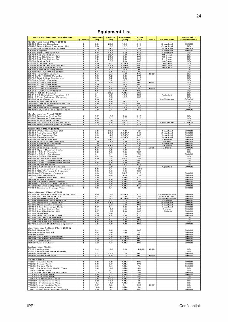
Equipment List
Major Equipment Description Diameter Height Pressure Temp Material ofQuantity (m) (m) (bar) (oC) Year Comments Construction
Cyclohexanone Plant (5000)C5401 Cooling Scrubber 1 2.0 22.6 12.8 215 3-packed 304SSC5402 Direct Heat Exchange Col 1 2.8 13.0 12.8 215 2-packed CSC5501 Cyclohexane Absorber 1 0.9 14.3 12.8 90 2-packed 304SSC5601 Stripper 1 1.2 13.6 2.3 175 1-packed 304SSC5602 Salt Extraction Col 1 1.8 11.4 5.2 115 1-packed CSC5701 1st Distillation Col 1 2.3 20.4 7.3 175 18-Sieve CSC5702 2nd Distillation Col 1 2.2 21.5 7.3 175 18-Sieve CSC5703 3rd Distillation Col 1 3.2 25.9 7.3 190 21-Sieve CSC5801 Drying Col 1 1.2 16.3 2.3 190 14-Sieve CSC5802 Fore Run Col 1 1.6 38.3 1.8/FV 190 60-Sieve CSC5803 Anone Distillation Col 1 3.0 49.7 1.8/FV 190 80-Valve CSC5804 Anol Distillation Col 1 3.0 28.6 1.8/FV 190 30-Sieve CSE5502 Ammonia Evaporator 1 1.3 6.2 26.4 75 CSE5701A/B - C5701 Reboilers 2 1.1 5.5 16.8 280 CSE5702 - C5702 Reboiler 1 1.7 6.7 7.3 175 1988 CSE5703A/B - C5703 Reboiler 2 1.6 7.2 7.3 175 CSE5705 Distillation Condenser 1 2.3 7.2 2.3 115 CSE5801 - C5801 Reboiler 1 1.0 5.2 16.8 280 CSE5802 - C5802 Reboiler 1 1.1 4.0 16.8 280 1987 CSE5806 - C5803 Reboiler 1 1.0 5.2 16.8 280 CSE5807 - C5803 Condenser 1 1.8 7.7 1.8 115 CSE5812 - C5804 Reboiler 1 1.4 5.4 16.8 280 1999 CSE5813 - C5804 Condenser 1 1.5 6.4 1.8 130 CSF5901 Hot Oil Furnace 1 3.1 23.2 ATM 565 CSR5411-14 Oxidation Reactors 1-4 4 3.4 6.0 12.8 190 Agitated CSR5419 Post Oxidation Reactor 1 3.4 6.5 12.8 190 CSR5901 Anol Reactor 1 2.6 7.2 1,483 tubes CS/CSS5401 Water Separator 1 2.5 7.6 14.3 175 CSS5601-3 Separator/Neutralizer 1-3 3 2.6 7.8 20.4 190 CSS5702 Reflux Vessel 1 3.1 7.7 2.3 115 CSV5004 Ammonia Storage Tank 1 1.5 8.2 27.5 62 CSV5401A Cyclohexane Recirc Tank 1 3.8 8.4 2.3 115 304SS
Cyclohexane Plant (5200)C5201 Benzene Drying Col 1 0.7 12.5 2.6 115 CSE5205 Benzene Evaporator 1 1.8 6.1 3.7 315 CSE5208 Waste Heat Boiler 1 2.4 5.8 20.9 226 CSR5201 1st Reactor (0.3% Pt on Al) 1 1.8 6.8 34.0 315 2,664 tubes CS/CSR5202 Post Reactor (ZnO + Pt/Al) 1 2.2 5.2 34.0 315 CS
Oximation Plant (6000)C6301 Water Extraction Col 1 0.5 20.0 1.8 85 4-packed 304SSC6401 1st Vacuum Col 1 1.9 20.8 2.0/FV 140 2-packed 304SSC6402 2nd Vacuum Col 1 1.0 14.9 1.8/FV 165 1-packed 304SSC6501 Extraction Col 1 2.0 11.8 3.5/FV 115 1-packed 304SSC6502 Toluene Stripper 1 2.1 24.5 2.1 135 21-sieve 304SSC6503 Waste Water Stripper 1 0.9 11.8 2.0 125 9-sieve 304SSC6601 Ammonia Absorber 1 0.8 9.2 7.3 125 2-packed 304SSC6701 NOx Absorber 1 3.0 54.1 7.5 95 31-sieve 304SSC6702 Bleaching Tower 1 1.3 7.3 7.5 95 2005 6-trays 304SSE6201 Hyam Reactor Cooler 1 1.3 9.5 5.0 55 CSE6401 - C6401 Reboiler 1 1.2 5.3 3.3 185 CSE6402 - C6401 Condenser 1 1.1 5.1 1.8 85 304SSE6502 - C6502 Reboiler 1 1.2 5.0 5.3 190 CSE6603 Ammonia Evaporator 1 2.0 6.2 26.4 75 CSE6604 - R6601 Waste Heat Boiler 1 2.1 5.6 6.5 350 CSE6802 - R6801 Waste Heat Boiler 1 1.6 4.6 6.0 350 CSR6201 Hyam Reactor 1 2.1 23.2 31.8 115 CSR6301-07 Oximation Reactors 7 3.7 3.0 0.1 85 Agitated 304SSR6601 Ammonia Burner (+1 spare) 2 1.5 2.1 6.5 1000R6801 NOx Remover (+1 spare) 2 1.8 1.6 6.0 750S6201A-F Filtration Vessels 6 1.6 3.5 34.0 115 304SSS6801 Mist Separator 1 1.6 7.0 7.5 75 304SST6201 - R6201 Let-down Tank 1 4.8 6.1 ATM 115 304SSV6204 Buffer Vessel 1 5.8 7.6 ATM 115 304SSV6403 Toluene Oxime Vessel 1 4.8 3.8 ATM 80 304SSV6701/2 - C6701 Buffer Vessels 2 5.8 7.6 ATM 80 304SSV7203A/B Crude Caprolactam Tanks 2 5.0 6.1 ATM 115 304SSV7301 Benzene Storage Tank 1 4.8 6.1 ATM 65 304SS
Caprolactam Plant (7000)C7301 Ammonium Sulf Extraction Col 1 1.0 13.8 3.6/FV 115 Pulsating-Pack 304SSC7302 CPL Extraction Col 1 1.7 18.1 1.8 85 Rotating Disc 304SSC7303 Re-extraction Col 1 1.7 16.3 4.0/FV 115 Pulsating-Pack 304SSC7304 Benzene Distillation Col 1 1.0 6.1 2.3 115 12-sieve 304SSC7305 Benzene Stripper Col 1 1.8 14.5 2.3 165 2-packed 304SSC7306 Condensate Stripper 1 0.4 3.7 2.3 165 1-packed 304SSC7401-6 Ion Exchange Beds 6 1.7 4.4 7.3 115 1-packed 304SSC7601 1st Distillation Col 1 1.4 10.5 4.8 165 8-sieve 304SSC7602 2nd Distillation Col 1 2.7 13.9 2.8 135 10-sieve 304SSC7801 Scrubber 1 0.9 3.8 - 115 304SSE7202 Neutralization Cooler 1 1.0 7.4 3.8 115 304SSE7601 1st Dist Col Reboiler 1 1.2 5.1 5.3 190 CSE7602 2nd Dist Col Reboiler 1 1.5 4.7 4.8 165 CSE7604 2nd Dist Col Condenser 1 1.5 7.5 2.8 115 CSS7702 Lactam Distillation Separator 1 2.5 7.9 1.8 165 304SS
Ammonium Sulfate Plant (8500)E8502 Heater #2 1 1.4 4.0 1.8 103 304SSE8504 Condenser #1 1 1.2 6.6 1.8 67 304SSG8501 Dryer 1 2.3 8.4 0.1 180 304SSV8501 1st Effect Evaporator 1 3.2 6.5 0.5/FV 120 304SSV8504 2nd Effect Evaporator 1 3.8 7.1 0.9.FV 100 304SSX8501 Crystallizer 1 7.2 9.3 ATM 100 304SSX8503 Wet Scrubber 1 3.2 7.7 ATM 103 304SS
Incinerator (0100)F0101 Incinerator 1 3.4 12.3 0.3 1,200 1999 CSF0201 Incinerator (abandoned) 1 CSS0105 Separator 1 3.2 22.6 0.3 100 304SSV0102 Smelt Dissolver 1 4.2 4.5 0.2 100 1999 304SS
Tank FarmsT0201 Caustic Tank 1 5.8 6.9 ATM 132 304SST0202 Oleum Tank 1 1.5 2.7 ATM 172 304SST0203 Sulfate Tank 1 4.0 5.4 ATM 73 304SST0301 Sulfuric Acid (98%) Tank 1 8.2 10.6 ATM 45 CST0302 Oleum Tank 1 8.1 9.1 ATM 45 CST0303 Ammonium Sulfate Tank 1 10.4 12.1 ATM 60 304SST0304A Caustic Tank 1 4.8 6.1 ATM 55 304SST0304B Caustic Tank 1 2.9 20.0 17.6 343 CST5201A/B Benzene Tanks 2 8.5 10.6 ATM 65 CST5202A Cyclohexane Tank 1 8.2 10.6 ATM 65 CST5202B Cyclohexane Tank 1 13.4 15.6 ATM 65 CST5802A Intermediate Tank 1 5.7 7.6 0.1 190 1987 CST5803 Cyclohexanone Tank 1 11.6 14.4 ATM 90 CST7801A/B/C Caprolactam Tanks 3 9.0 12.1 ATM 140 304SS