fac-37b (yanmar) fac-37bc (yanmar) fac-52b (yanmar) fac ... · fac-37b (yanmar) fac-37bc (yanmar)...
TRANSCRIPT
FAC-37B (YANMAR)FAC-37BC (YANMAR)FAC-52B (YANMAR)FAC-52BC (YANMAR)
Preface
This service manual explains about the cautions for maintenance jobs and is to serve a
guide for the electric system, and troubleshooting for service personnel.
In this book the fundamental matters and other things already mentioned in the
“Instruction Manual” and the “Parts Catalog” are omitted to avoid duplication.
Therefore, for the operation and handling of this unit, we request you to refer to the
instruction manual and caution plates, and further for the structure and components of
the unit, please refer to the “Parts Catalog” separately to be supplied with the unit.
If you should find any description which does not coincide with the instruction manual
and parts catalog, we request you to make sure to start the job after clarifying it.
Service personnel is required to safely take quick and proper countermeasures as well
as to use correct technology of maintenance in case of field services and periodical
maintenance. It is important that service personnel should have proper and sufficient
knowledge about the structure and function of the unit and should be well familiar with
such technique mentioned in them.
Regarding the part numbers mentioned in this manual, we request you to refer to the
Parts catalog separately supplied together with the unit, because the parts numbers in
this manual are sometimes changed.
Copies of this service manual are intended to be distributed to limited numbers of our customers. The unauthorized reproduction or distribution of this service manual is prohibited.
Table of Contents
1. Specification -------------------------------------------------------------------------------------- 1-1 1.1 Specifications ----------------------------------------------------------------------------------------------------------- 1-1 1.2 Set Value ----------------------------------------------------------------------------------------------------------------- 1-2 1.3 Outline Drawing -------------------------------------------------------------------------------------------------------- 1-3 1.4 Internal Components and Part Names ---------------------------------------------------------------------------- 1-5 1.5 Instrument Panel ------------------------------------------------------------------------------------------------------- 1-7 1.6 Capacity Control Device ---------------------------------------------------------------------------------------------- 1-9 1.7 Piping Diagram --------------------------------------------------------------------------------------------------------- 1-12 1.8 Fuel Piping --------------------------------------------------------------------------------------------------------------- 1-16
2. Maintenance --------------------------------------------------------------------------------------- 2-1 2.1 Cautions for Overhauling --------------------------------------------------------------------------------------------- 2-1 2.2 Tightening Torque ----------------------------------------------------------------------------------------------------- 2-2 2.3 How to adjust Regulator and How to replace Diaphragm ---------------------------------------------------- 2-5 2.4 Clean of Element in Sedimenter ------------------------------------------------------------------------------------ 2-8 2.5 Change Oil separator ------------------------------------------------------------------------------------------------- 2-8 2.6 Change O-Ring of Unloader ----------------------------------------------------------------------------------------- 2-9 2.7 Check O-ring and Needle valve of Auto-relief valve and Vacuum relief valve -------------------------- 2-9 2.8 Performance check of Pressure control valve ------------------------------------------------------------------ 2-10 2.9 Check Pressure control valve O-Ring and Piston -------------------------------------------------------------- 2-10 2.10 Change of Pellet assembly of By-pass valve [PDS175S(SC)-5C3 only] --------------------------------- 2-11 2.11 Clean inside of Fuel tank --------------------------------------------------------------------------------------------- 2-12 2.12 Values of Various Adjustments of Engine ------------------------------------------------------------------------ 2-13
3. Electric System ----------------------------------------------------------------------------------- 3-1 3.1 Control -------------------------------------------------------------------------------------------------------------------- 3-1 3.2 Alternator [Dynamo regulator (IC type)] -------------------------------------------------------------------------- 3-7 3.3 Starter --------------------------------------------------------------------------------------------------------------------- 3-9 3.4 Safety relay -------------------------------------------------------------------------------------------------------------- 3-10 3.5 Solenoid relay・Heater relay ----------------------------------------------------------------------------------------- 3-11 3.6 Starting unloader Solenoid valve [PDS175S(SC)-5C3 only] ------------------------------------------------ 3-12 3.7 Stop solenoid ------------------------------------------------------------------------------------------------------------ 3-12 3.8 Engine oil pressure Switch (For emergency stops) ------------------------------------------------------------ 3-13 3.9 Fuel air-bleeding Electromagnetic Pump ------------------------------------------------------------------------- 3-13 3.10 Discharge air temperature Sensor・Coolant temperature Sensor ------------------------------------------ 3-13 3.11 Fuel meter (Display) --------------------------------------------------------------------------------------------------- 3-14 3.12 Sending unit ------------------------------------------------------------------------------------------------------------- 3-15
4. Troubleshooting --------------------------------------------------------------------------------- 4-1 4.1 Repairing Procedures ------------------------------------------------------------------------------------------------- 4-1 4.2 Failures of Compressor and Engine ------------------------------------------------------------------------------- 4-3 4.3 Operation of Emergency Switch ------------------------------------------------------------------------------------ 4-9 4.4 Others --------------------------------------------------------------------------------------------------------------------- 4-12 4.5 Explanation of Trouble diagnosis ---------------------------------------------------------------------------------- 4-13
5. References ----------------------------------------------------------------------------------------- 5-1 5.1 Comparison between Consumable parts and Electrical appliances --------------------------------------- 5-1 5.2 Engine Wiring Diagram ----------------------------------------------------------------------------------------------- 5-3
1. Specification
1-1
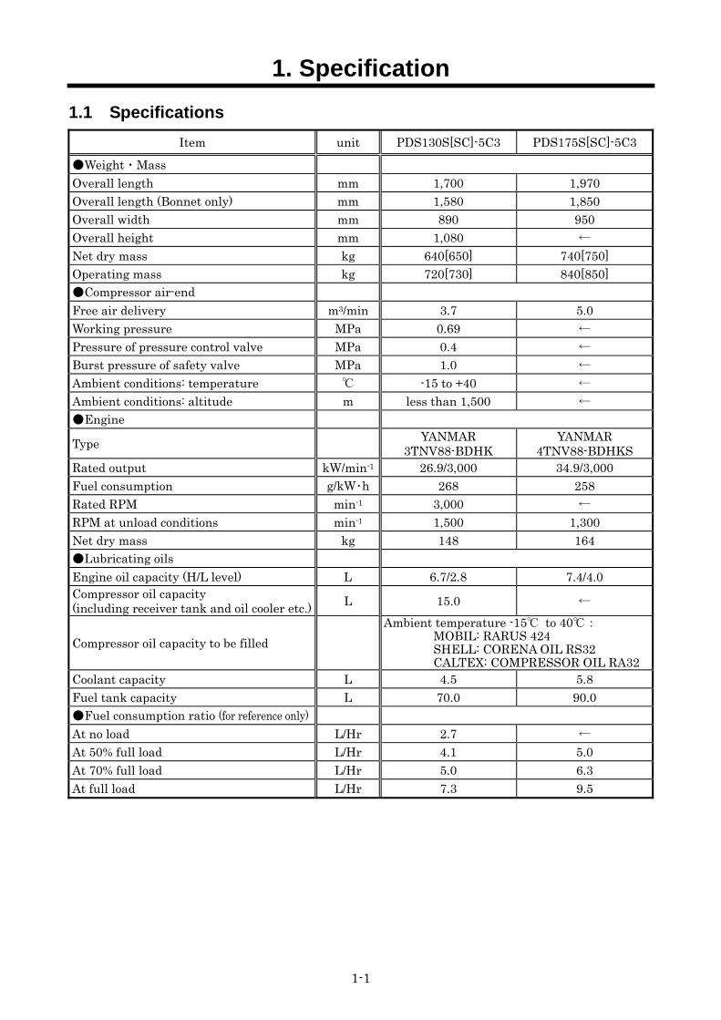
1.1 Specifications Item unit PDS130S[SC]-5C3 PDS175S[SC]-5C3
Weight・Mass Overall length mm 1,700 1,970 Overall length (Bonnet only) mm 1,580 1,850 Overall width mm 890 950 Overall height mm 1,080 ← Net dry mass kg 640[650] 740[750] Operating mass kg 720[730] 840[850] Compressor air-end Free air delivery m3/min 3.7 5.0 Working pressure MPa 0.69 ← Pressure of pressure control valve MPa 0.4 ← Burst pressure of safety valve MPa 1.0 ← Ambient conditions: temperature -15 to +40 ← Ambient conditions: altitude m less than 1,500 ← Engine
Type YANMAR 3TNV88-BDHK
YANMAR 4TNV88-BDHKS
Rated output kW/min-1 26.9/3,000 34.9/3,000 Fuel consumption g/kW・h 268 258 Rated RPM min-1 3,000 ← RPM at unload conditions min-1 1,500 1,300 Net dry mass kg 148 164 Lubricating oils Engine oil capacity (H/L level) L 6.7/2.8 7.4/4.0 Compressor oil capacity (including receiver tank and oil cooler etc.) L 15.0 ←
Compressor oil capacity to be filled Ambient temperature -15 to 40:
MOBIL: RARUS 424 SHELL: CORENA OIL RS32 CALTEX: COMPRESSOR OIL RA32
Coolant capacity L 4.5 5.8 Fuel tank capacity L 70.0 90.0 Fuel consumption ratio (for reference only) At no load L/Hr 2.7 ← At 50% full load L/Hr 4.1 5.0 At 70% full load L/Hr 5.0 6.3 At full load L/Hr 7.3 9.5
1. Specification
1-2
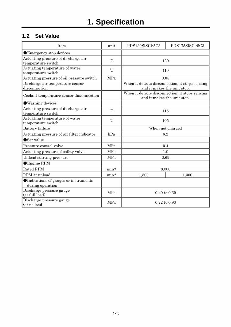
1.2 Set Value Item unit PDS130S[SC]-5C3 PDS175S[SC]-5C3
Emergency stop devices Actuating pressure of discharge air temperature switch 120 Actuating temperature of water temperature switch 110
Actuating pressure of oil pressure switch MPa 0.05 Discharge air temperature sensor disconnection When it detects disconnection, it stops sensing
and it makes the unit stop. Coolant temperature sensor disconnection When it detects disconnection, it stops sensing
and it makes the unit stop. Warning devices Actuating pressure of discharge air temperature switch 115 Actuating temperature of water temperature switch 105
Battery failure When not charged Actuating pressure of air filter indicator kPa 6.2 Set value Pressure control valve MPa 0.4 Actuating pressure of safety valve MPa 1.0 Unload starting pressure MPa 0.69 Engine RPM Rated RPM min-1 3,000 RPM at unload min-1 1,500 1,300 Indications of gauges or instruments
during operation
Discharge pressure gauge (at full load) MPa 0.40 to 0.69 Discharge pressure gauge (at no load) MPa 0.72 to 0.90
1. Specification
1-3
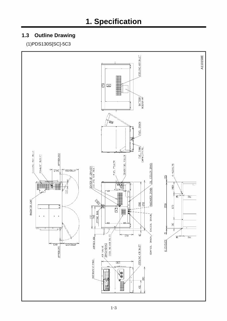
1.3 Outline Drawing (1)PDS130S[SC]-5C3
A11
0158
E
1. Specification
1-4
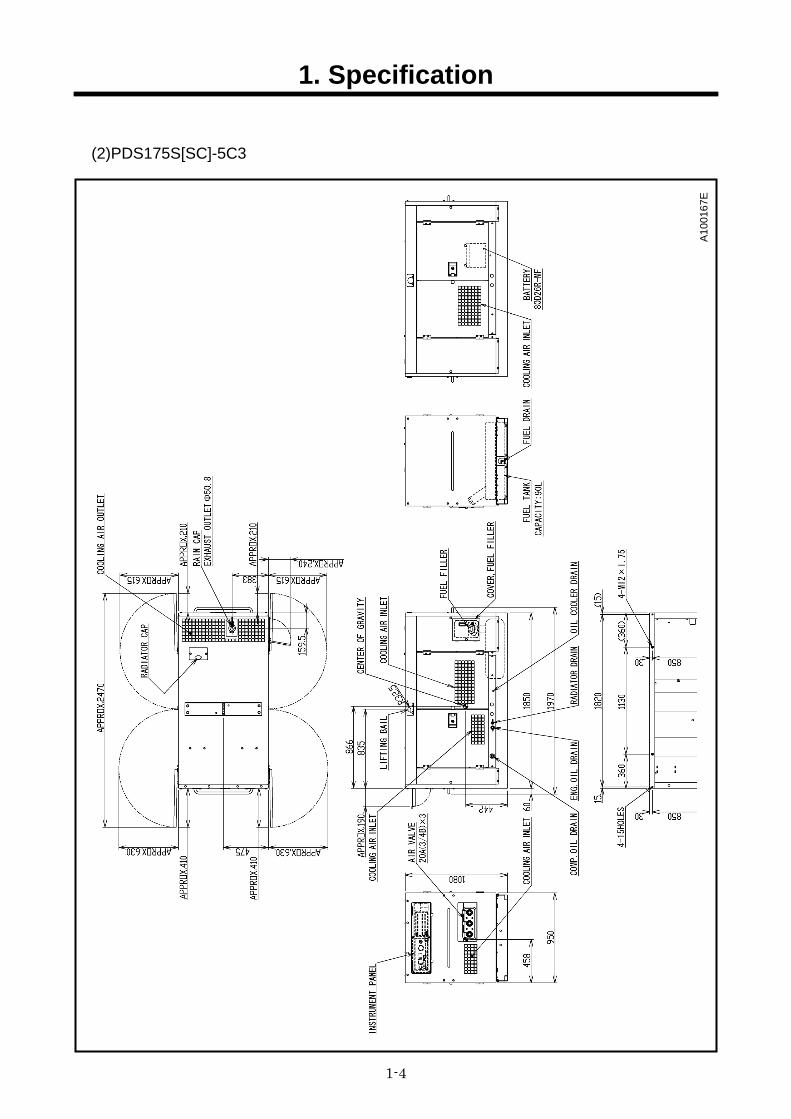
(2)PDS175S[SC]-5C3
A10
0167
E
1. Specification
1-5
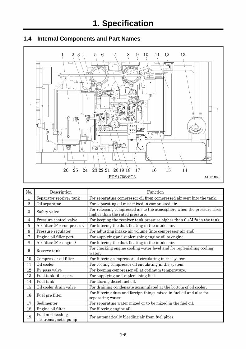
1.4 Internal Components and Part Names
PDS175S-5C3 A100186E
No. Description Function 1 Separator receiver tank For separating compressor oil from compressed air sent into the tank. 2 Oil separator For separating oil mist mixed in compressed air.
3 Safety valve For releasing compressed air to the atmosphere when the pressure rises higher than the rated pressure.
4 Pressure control valve For keeping the receiver tank pressure higher than 0.4MPa in the tank.5 Air filter (For compressor) For filtering the dust floating in the intake air. 6 Pressure regulator For adjusting intake air volume (into compressor air-end) 7 Engine oil filler port For supplying and replenishing engine oil to engine. 8 Air filter (For engine) For filtering the dust floating in the intake air.
9 Reserve tank For checking engine cooling water level and for replenishing cooling water.
10 Compressor oil filter For filtering compressor oil circulating in the system. 11 Oil cooler For cooling compressor oil circulating in the system. 12 By-pass valve For keeping compressor oil at optimum temperature. 13 Fuel tank filler port For supplying and replenishing fuel. 14 Fuel tank For storing diesel fuel oil. 15 Oil cooler drain valve For draining condensate accumulated at the bottom of oil cooler.
16 Fuel pre filter For filtering dust and foreign things mixed in fuel oil and also for separating water.
17 Sedimenter For separating water mixed or to-be mixed in the fuel oil. 18 Engine oil filter For filtering engine oil.
19 Fuel air-bleeding electromagnetic pump For automatically bleeding air from fuel pipes.
1 2 3 4 5 6 7 8 9 10 11 12 13
26 25 24 23 22 21 20 19 18 17 16 15 14
1. Specification
1-6
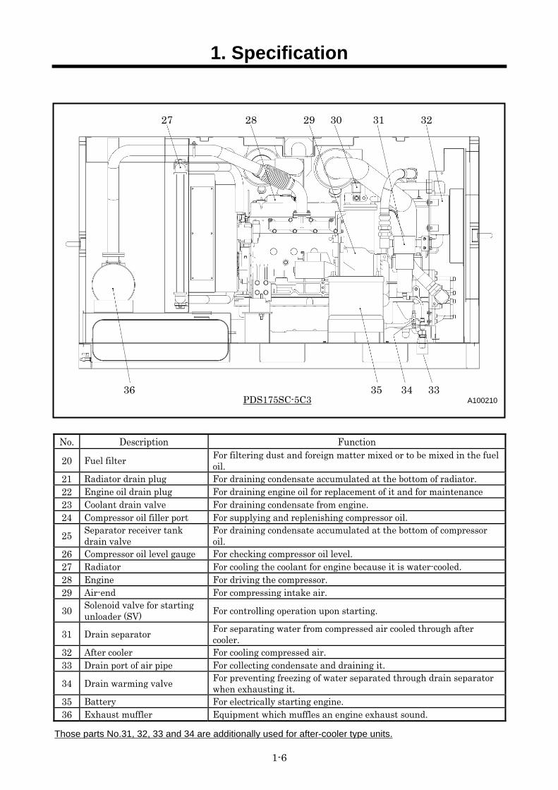
PDS175SC-5C3 A100210
27 28 29 30 31 32
36 35 34 33
No. Description Function
20 Fuel filter For filtering dust and foreign matter mixed or to be mixed in the fuel oil.
21 Radiator drain plug For draining condensate accumulated at the bottom of radiator. 22 Engine oil drain plug For draining engine oil for replacement of it and for maintenance 23 Coolant drain valve For draining condensate from engine. 24 Compressor oil filler port For supplying and replenishing compressor oil.
25 Separator receiver tank drain valve
For draining condensate accumulated at the bottom of compressor oil.
26 Compressor oil level gauge For checking compressor oil level. 27 Radiator For cooling the coolant for engine because it is water-cooled. 28 Engine For driving the compressor. 29 Air-end For compressing intake air.
30 Solenoid valve for starting unloader (SV) For controlling operation upon starting.
31 Drain separator For separating water from compressed air cooled through after cooler.
32 After cooler For cooling compressed air. 33 Drain port of air pipe For collecting condensate and draining it.
34 Drain warming valve For preventing freezing of water separated through drain separator when exhausting it.
35 Battery For electrically starting engine. 36 Exhaust muffler Equipment which muffles an engine exhaust sound.
Those parts No.31, 32, 33 and 34 are additionally used for after-cooler type units.
1. Specification
1-7
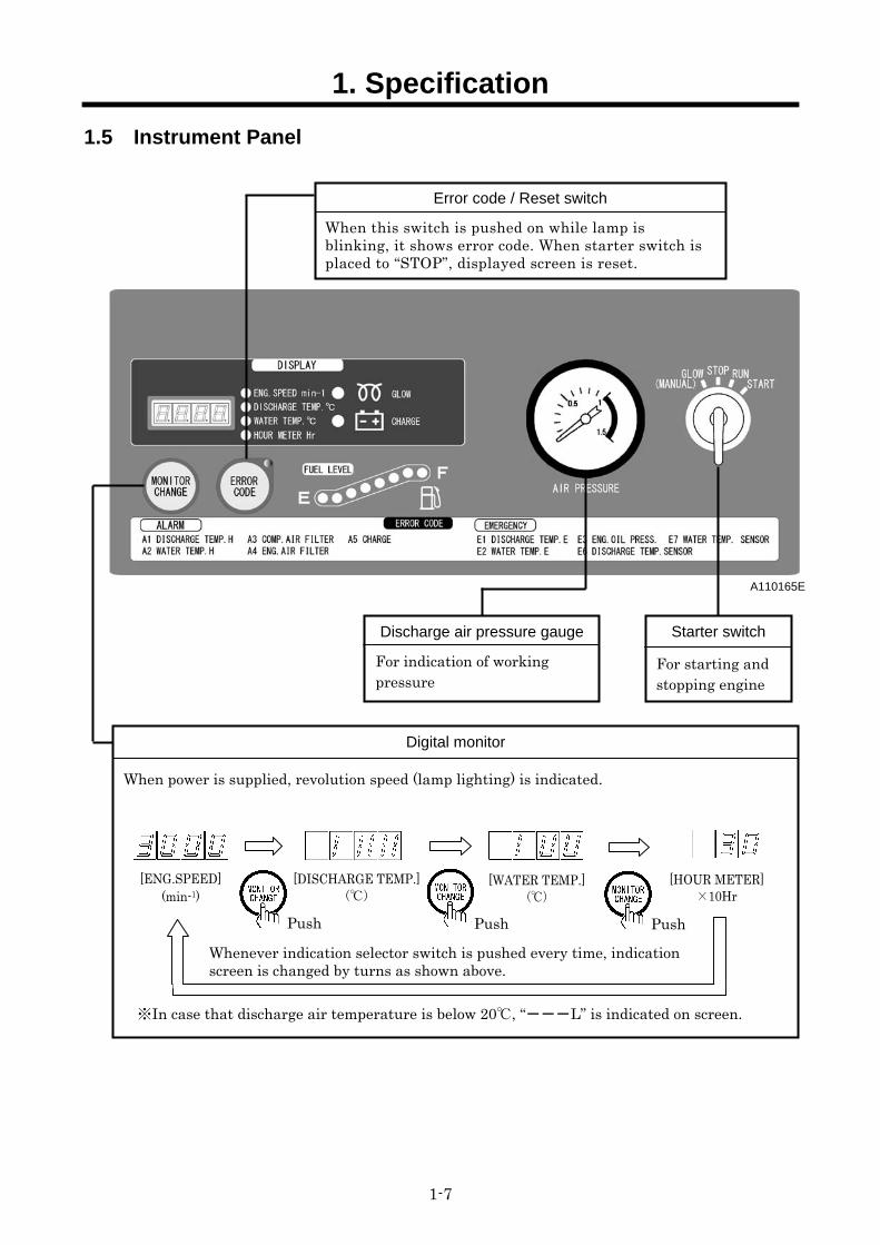
1.5 Instrument Panel
A110165E
Error code / Reset switch
When this switch is pushed on while lamp is blinking, it shows error code. When starter switch is placed to “STOP”, displayed screen is reset.
Starter switch
For starting and stopping engine
Discharge air pressure gauge
For indication of working pressure
Digital monitor
When power is supplied, revolution speed (lamp lighting) is indicated.
[ENG.SPEED] (min-1)
[DISCHARGE TEMP.] ()
[WATER TEMP.]()
[HOUR METER]×10Hr
Push
Whenever indication selector switch is pushed every time, indication screen is changed by turns as shown above.
※In case that discharge air temperature is below 20, “---L” is indicated on screen.
Push Push
1. Specification
1-8
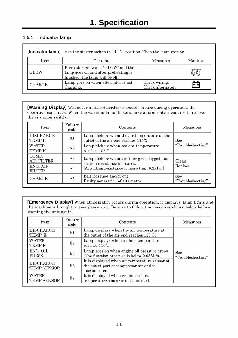
1.5.1 Indicator lamp
[Indicator lamp] Turn the starter switch to “RUN” position. Then the lamp goes on.
Item Contents Measures Monitor
GLOW Press starter switch “GLOW” and the lamp goes on and after preheating is finished, the lamp will be off.
―
CHARGE Lamp goes on when alternator is not charging.
Check wiring. Check alternator.
[Warning Display] Whenever a little disorder or trouble occurs during operation, the operation continues. When the warning lamp flickers, take appropriate measures to recover the situation swiftly.
Item Failure code Contents Measures
DISCHARGE TEMP.H A1 Lamp flickers when the air temperature at the
outlet of the air-end reaches 115. WATER TEMP.H A2 Lamp flickers when coolant temperature
reaches 105.
See “Troubleshooting”
COMP. AIR FILTER A3 ENG. AIR FILTER A4
Lamp flickers when air filter gets clogged and suction resistance increases. [Actuating resistance is more than 6.2kPa.]
Clean Replace
CHARGE A5 Belt loosened and/or cut Faulty generation of alternator
See “Troubleshooting”
[Emergency Display] When abnormality occurs during operation, it displays, lamp lights and the machine is brought to emergency stop. Be sure to follow the measures shown below before starting the unit again.
Item Failure code Contents Measures
DISCHARGE TEMP. E E1 Lamp displays when the air temperature at
the outlet of the air-end reaches 120. WATER TEMP.E E2 Lamp displays when coolant temperature
reaches 110. ENG. OIL PRESS. E3 Lamp goes on when engine oil pressure drops.
[The function pressure is below 0.05MPa.] DISCHARGE TEMP.SENSOR E6
It is displayed when air temperature sensor at the outlet port of compressor air end is disconnected.
WATER TEMP.SENSOR E7 It is displayed when engine coolant
temperature sensor is disconnected.
See “Troubleshooting”
1. Specification
1-9
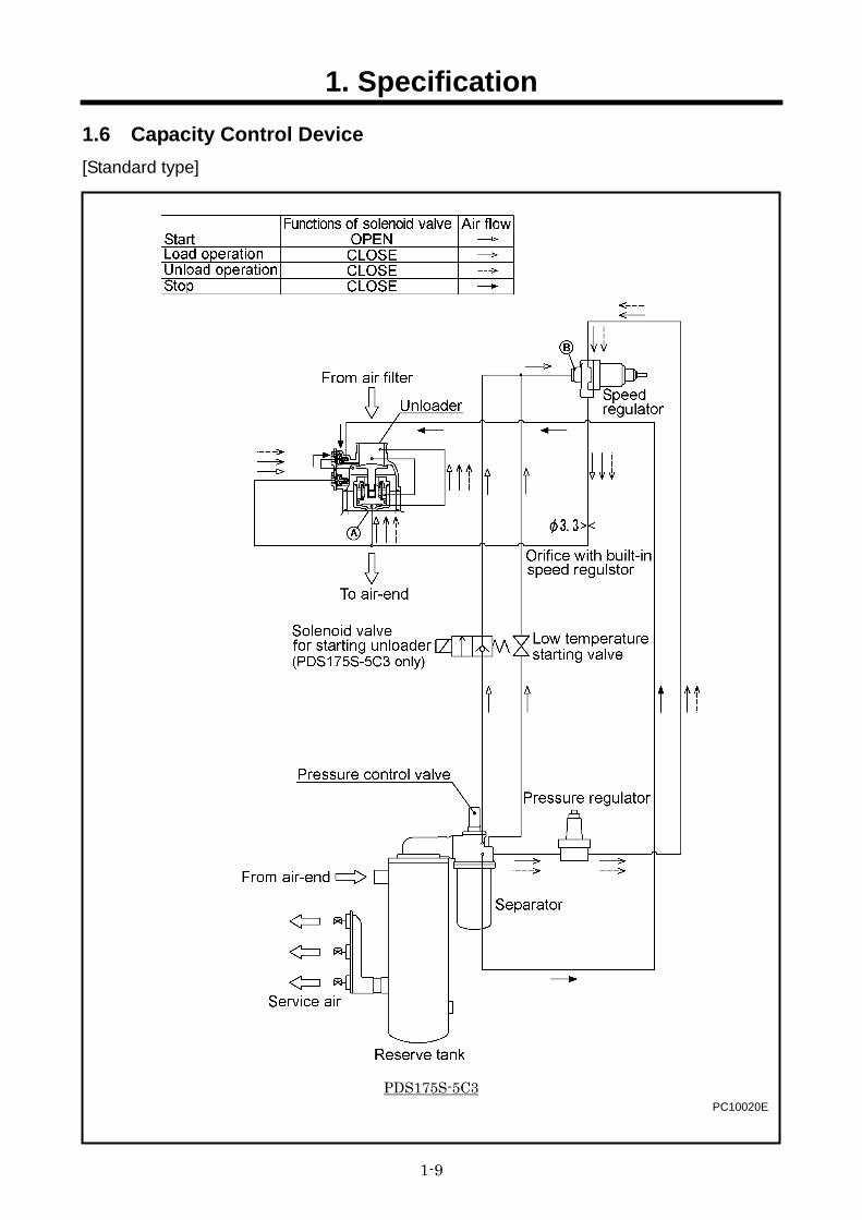
1.6 Capacity Control Device [Standard type]
PDS175S-5C3
PC10020E
1. Specification
1-10
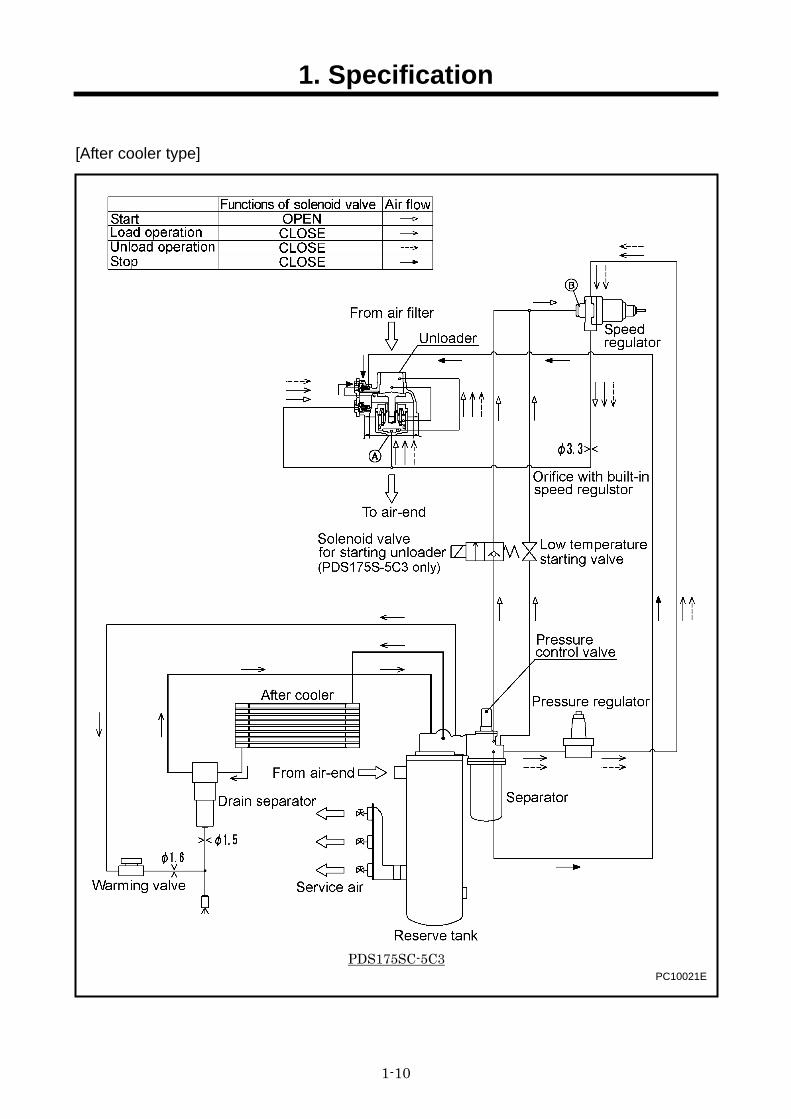
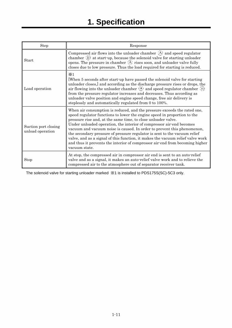
[After cooler type]
PDS175SC-5C3 PC10021E
1. Specification
1-11
Step Response
Start Compressed air flows into the unloader chamber and speed regulator chamber at start-up, because the solenoid valve for starting unloader opens. The pressure in chamber rises soon, and unloader valve fully closes due to low pressure. Thus the load required for starting is reduced.
Load operation
※1 [When 5 seconds after start-up have passed the solenoid valve for starting unloader closes,] and according as the discharge pressure rises or drops, the air flowing into the unloader chamber and speed regulator chamber from the pressure regulator increases and decreases. Thus according as unloader valve position and engine speed change, free air delivery is steplessly and automatically regulated from 0 to 100%.
Suction port closing unload operation
When air consumption is reduced, and the pressure exceeds the rated one, speed regulator functions to lower the engine speed in proportion to the pressure rise and, at the same time, to close unloader valve. Under unloaded operation, the interior of compressor air-end becomes vacuum and vacuum noise is caused. In order to prevent this phenomenon, the secondary pressure of pressure regulator is sent to the vacuum relief valve, and as a signal of this function, it makes the vacuum relief valve work and thus it prevents the interior of compressor air-end from becoming higher vacuum state.
Stop At stop, the compressed air in compressor air end is sent to an auto-relief valve and as a signal, it makes an auto-relief valve work and to relieve the compressed air to the atmosphere out of separator receiver tank.
The solenoid valve for starting unloader marked ※1 is installed to PDS175S(SC)-5C3 only.
1. Specification
1-12
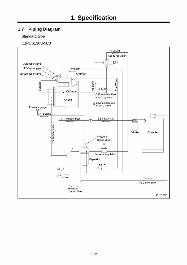
1.7 Piping Diagram Standard type
(1)PDS130S-5C3
A110186E
1. Specification
1-13
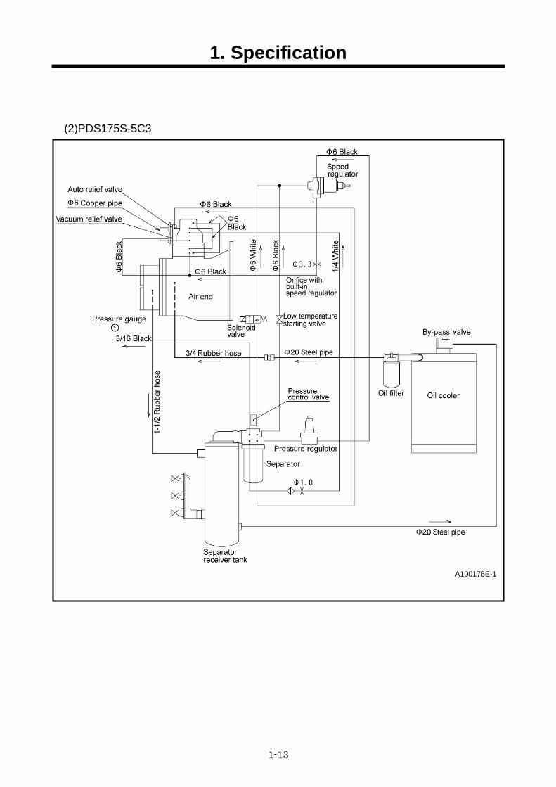
(2)PDS175S-5C3
A100176E-1
1. Specification
1-14
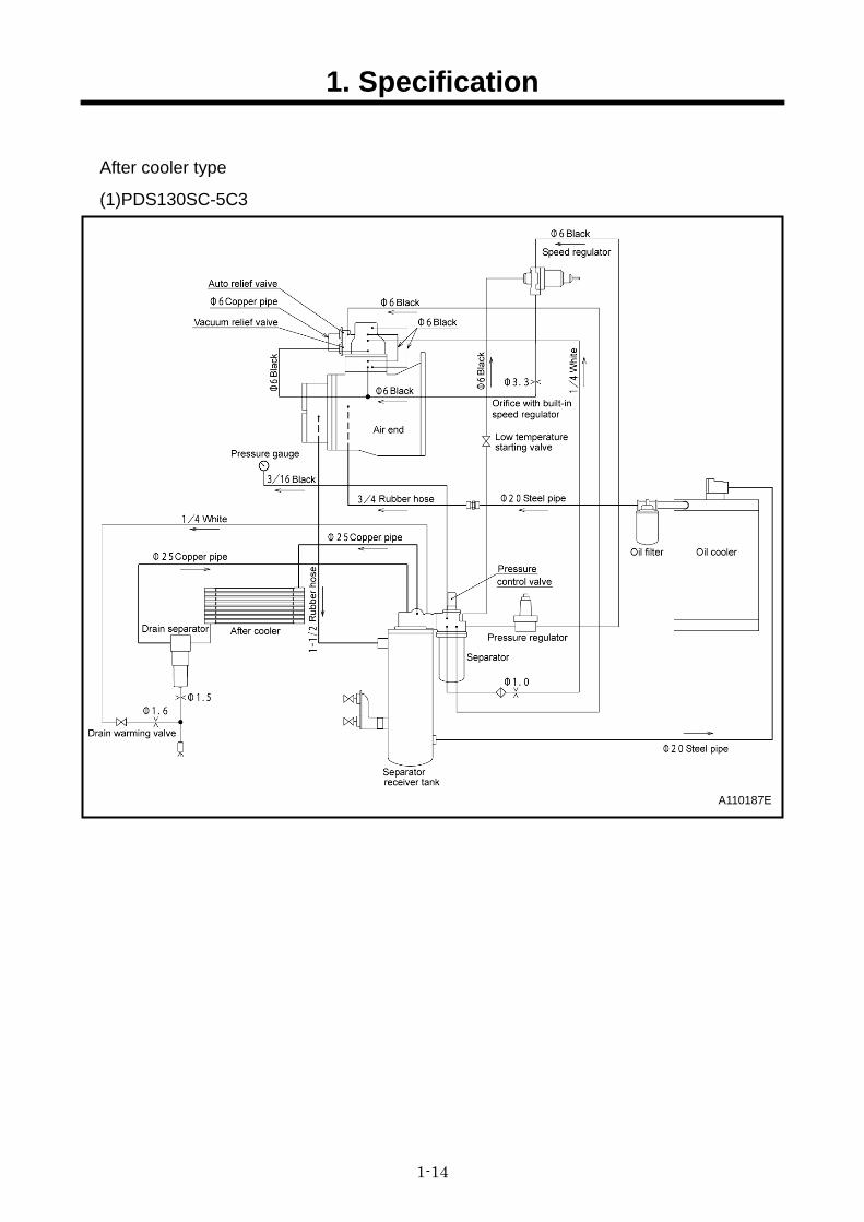
After cooler type
(1)PDS130SC-5C3
A110187E
1. Specification
1-15
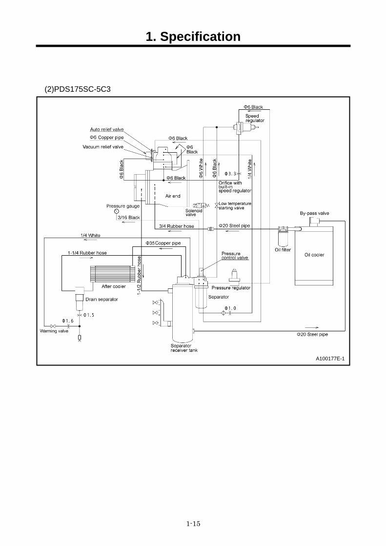
(2)PDS175SC-5C3
A100177E-1
1. Specification
1-16
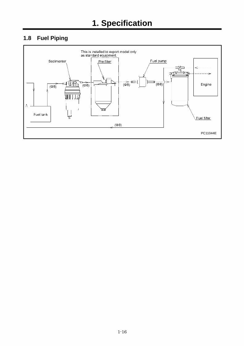
1.8 Fuel Piping
PC11044E
2. Maintenance
2-1
2.1 Cautions for Overhauling
2.1.1 Precautions before starting work (1)Work to be performed
It is very important to always plan in advance what facilities, tools, instruments, materials, oil, etc. you will need to use; the exact locations and methods of performing inspection, adjustment, or disassembly; and the key points of any repair work to be performed.
(2)Care not to spill oil Use a pan to collect used compressor oil, engine oil when changing the oil or attaching or detaching an oil line. If a large volume of oil is expected to flow out make, sure to drain any accumulated oil from the reserve tank, engine oil pan in advance. [Follow the designated regulations to dispose of compressor oil and engine oil.]
(3)Care when detaching parts When disassembling a complicated part, put a matching mark to indicate the position of detached parts for future reference. Make sure that the negative cable is detached from the battery terminals before starting repair work.
(4)Tools to be prepared ①Measuring instruments (e. g. tester, insulation resistance gauge etc.) ②Tools ③Torque wrenches ④Jigs and specialized tools ⑤Sealing tape (GAFLON seal tape) ⑥Liquid gasket (ThreeBond 1212) ⑦Lubricant (NICHIMOLY LAP spray or equivalent) ⑧Molybdenum sulfide (Paste spray type) ⑨Grease Lithium based all-purpose grease [CALTEX MULTIFAK EP1] Lithium natrium based heat resistant grease [MULTINOC SDX]
⑩Diesel oil ⑪Compressor oil ⑫Cleaning cloths ⑬Literatures (such as manuals etc.)
2.1.2 Disassembly and assembly (1) Select such a place for component disassembly where it is enough spacious and shall be
dust-free. (2) Clean also the surroundings of the part or component to be disassembled, removing smudge
and adhesive matter by washing them. (3) Before removing nylon tubes, hydraulic hoses and also fuel hoses, clean the inside of the
machine unit. And also cover all the openings of them temporally to prevent foreign matter and dust from entering inside.
(4) When dismantling the disassembled parts or component, wash their surfaces well and place them on clean paper or cloth so that they can be kept clean and from being damaged.
(5) Check each part for any dirt and discoloration. Then wash it in detergent oil (diesel oil) slightly. However, do not wash rubber parts with diesel oil.
(6) Be careful not to damage disassembled parts, they are precision built. (7) Replace consumables such as oil seals, O-rings, filters, oil, etc. with new items when
reassembling parts. (8) Apply “CALTEX MULTIFAK EP1” to O-ring surface and “MULTINOC SDX” to sliding portion
of oil seal. (9) When reassembling, place the parts or components according to reassembling order and
reassemble them correctly without any part un-reassembled and un-used. (10) When reassembling an assembled part (set part), be sure to replace it as an assembly. (11) Make sure to follow the tightening torque and clearance when reassembling the disassembled
parts or components. (12) If the parts or components which are being disassembled are left untreated, ambient humidity
or dirt may cause rust or corrosion. If it is unavoidably necessary to stop disassembling job on the way, make sure to protect them against rust and dirt.
(13) After finishing the disassembling job, make sure to check the assembled unit for the direction of rotation, rotation speed and oil leak.
(14) At first, perform trial operation at so slow speed that it may not cause seizure or overheating.
2. Maintenance
2-2
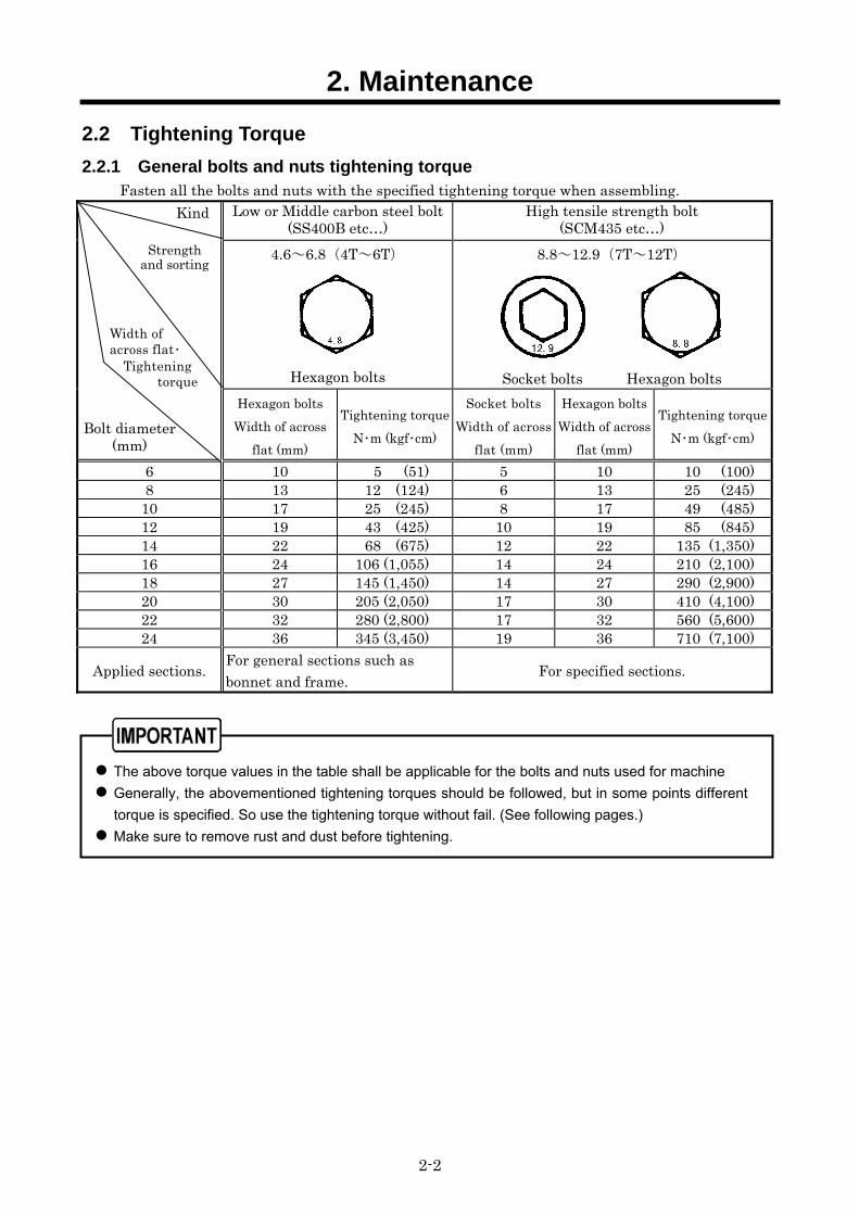
2.2 Tightening Torque 2.2.1 General bolts and nuts tightening torque
Fasten all the bolts and nuts with the specified tightening torque when assembling. Low or Middle carbon steel bolt
(SS400B etc…) High tensile strength bolt
(SCM435 etc…) 4.6~6.8(4T~6T)
Hexagon bolts
8.8~12.9(7T~12T)
Socket bolts Hexagon bolts
Hexagon bolts Width of across
flat (mm)
Tightening torqueN・m (kgf・cm)
Socket boltsWidth of across
flat (mm)
Hexagon bolts Width of across
flat (mm)
Tightening torqueN・m (kgf・cm)
6 10 5 (51) 5 10 10 (100) 8 13 12 (124) 6 13 25 (245)
10 17 25 (245) 8 17 49 (485) 12 19 43 (425) 10 19 85 (845) 14 22 68 (675) 12 22 135 (1,350) 16 24 106 (1,055) 14 24 210 (2,100) 18 27 145 (1,450) 14 27 290 (2,900) 20 30 205 (2,050) 17 30 410 (4,100) 22 32 280 (2,800) 17 32 560 (5,600) 24 36 345 (3,450) 19 36 710 (7,100)
Applied sections. For general sections such as bonnet and frame. For specified sections.
The above torque values in the table shall be applicable for the bolts and nuts used for machine
Generally, the abovementioned tightening torques should be followed, but in some points different
torque is specified. So use the tightening torque without fail. (See following pages.)
Make sure to remove rust and dust before tightening.
Bolt diameter (mm)
Kind
Strength and sorting
Width of across flat・
Tightening torque
2. Maintenance
2-3
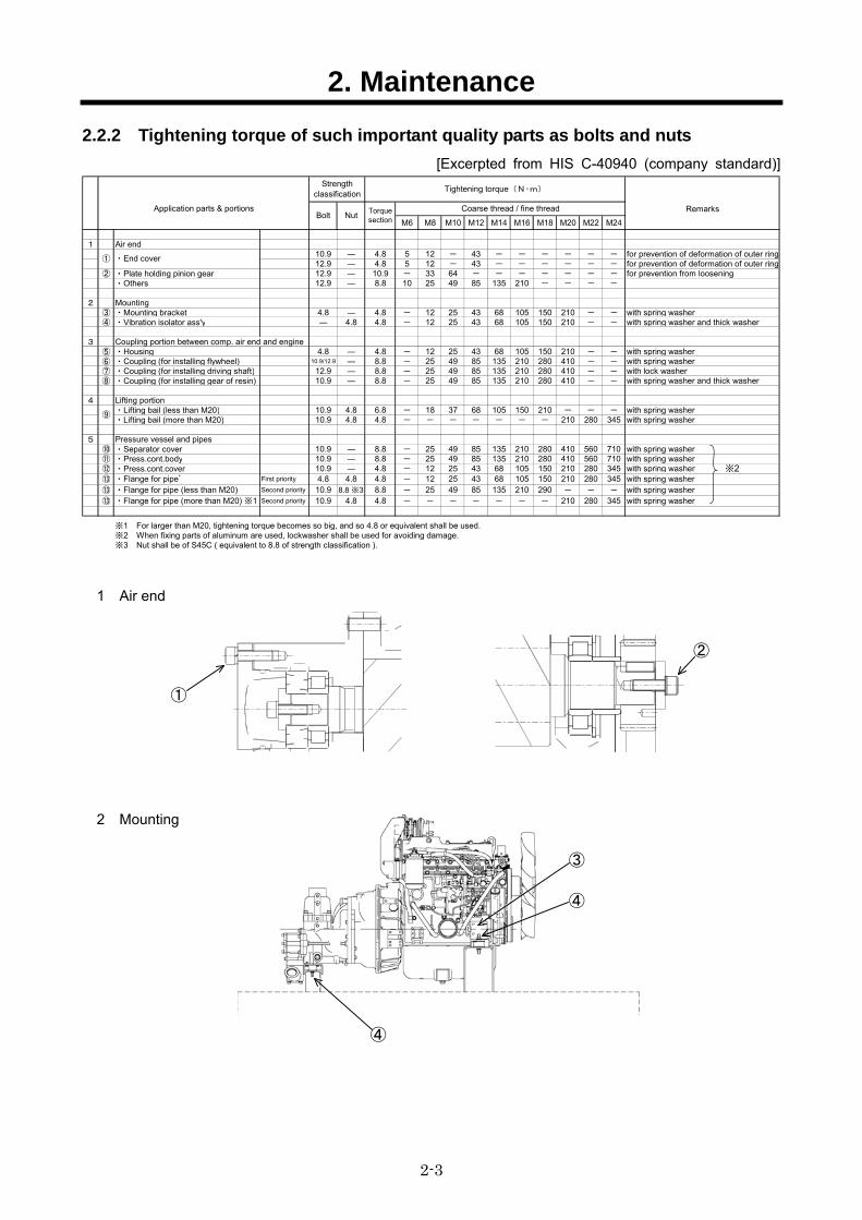
2.2.2 Tightening torque of such important quality parts as bolts and nuts [Excerpted from HIS C-40940 (company standard)]
Remarks
M6 M8 M10 M12 M14 M16 M18 M20 M22 M24
1 Air end10.9 ― 4.8 5 12 - 43 - - - - - - for prevention of deformation of outer ring12.9 ― 4.8 5 12 - 43 - - - - - - for prevention of deformation of outer ring
② ・Plate holding pinion gear 12.9 ― 10.9 - 33 64 - - - - - - - for prevention from loosening・Others 12.9 ― 8.8 10 25 49 85 135 210 - - - -
2 Mounting③ ・Mounting bracket 4.8 ― 4.8 - 12 25 43 68 105 150 210 - - with spring washer④ ・Vibration isolator ass'y ― 4.8 4.8 - 12 25 43 68 105 150 210 - - with spring washer and thick washer
3 Coupling portion between comp. air end and engine⑤ ・Housing 4.8 ― 4.8 - 12 25 43 68 105 150 210 - - with spring washer⑥ ・Coupling (for installing flywheel) 10.9/12.9 ― 8.8 - 25 49 85 135 210 280 410 - - with spring washer⑦ ・Coupling (for installing driving shaft) 12.9 ― 8.8 - 25 49 85 135 210 280 410 - - with lock washer⑧ ・Coupling (for installing gear of resin) 10.9 ― 8.8 - 25 49 85 135 210 280 410 - - with spring washer and thick washer
4 Lifting portion・Lifting bail (less than M20) 10.9 4.8 6.8 - 18 37 68 105 150 210 - - - with spring washer・Lifting bail (more than M20) 10.9 4.8 4.8 - - - - - - - 210 280 345 with spring washer
5 Pressure vessel and pipes⑩ ・Separator cover 10.9 ― 8.8 - 25 49 85 135 210 280 410 560 710 with spring washer⑪ ・Press.cont.body 10.9 ― 8.8 - 25 49 85 135 210 280 410 560 710 with spring washer⑫ ・Press.cont.cover 10.9 ― 4.8 - 12 25 43 68 105 150 210 280 345 with spring washer⑬ ・Flange for pipe゙ First priority 4.8 4.8 4.8 - 12 25 43 68 105 150 210 280 345 with spring washer⑬ ・Flange for pipe (less than M20) Second priority 10.9 8.8 ※3 8.8 - 25 49 85 135 210 290 - - - with spring washer⑬ ・Flange for pipe (more than M20) ※1 Second priority 10.9 4.8 4.8 - - - - - - - 210 280 345 with spring washer
※1 For larger than M20, tightening torque becomes so big, and so 4.8 or equivalent shall be used.※2 When fixing parts of aluminum are used, lockwasher shall be used for avoiding damage.※3 Nut shall be of S45C ( equivalent to 8.8 of strength classification ).
① ・End cover
⑨
Tightening torque(N・m)Strength
classification
Torquesection
Bolt NutCoarse thread / fine threadApplication parts & portions
※2
1 Air end
2 Mounting
②
①
④
④
③
2. Maintenance
2-4
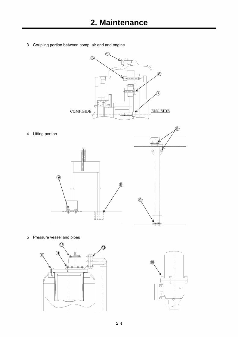
3 Coupling portion between comp. air end and engine
4 Lifting portion
5 Pressure vessel and pipes
⑦
⑤⑥
⑧
⑨ ⑨
⑨
⑨
⑬
⑩ ⑩
⑪
⑫
COMP.SIDE ENG.SIDE
2. Maintenance
2-5
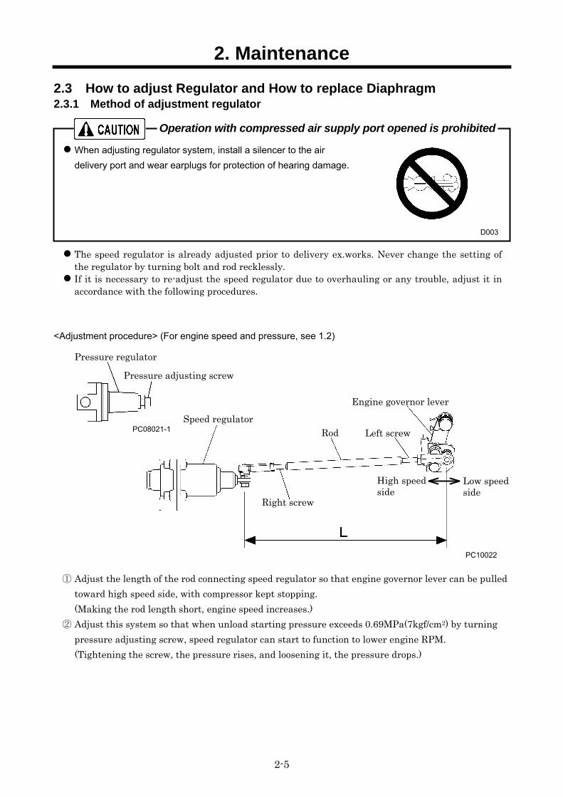
2.3 How to adjust Regulator and How to replace Diaphragm 2.3.1 Method of adjustment regulator
When adjusting regulator system, install a silencer to the air
delivery port and wear earplugs for protection of hearing damage.
The speed regulator is already adjusted prior to delivery ex.works. Never change the setting of the regulator by turning bolt and rod recklessly.
If it is necessary to re-adjust the speed regulator due to overhauling or any trouble, adjust it in accordance with the following procedures.
<Adjustment procedure> (For engine speed and pressure, see 1.2)
① Adjust the length of the rod connecting speed regulator so that engine governor lever can be pulled toward high speed side, with compressor kept stopping. (Making the rod length short, engine speed increases.)
② Adjust this system so that when unload starting pressure exceeds 0.69MPa(7kgf/cm2) by turning pressure adjusting screw, speed regulator can start to function to lower engine RPM. (Tightening the screw, the pressure rises, and loosening it, the pressure drops.)
D003
PC10022
Speed regulator Engine governor lever
Rod Left screw
Right screw
Low speedside
High speed side
Pressure adjusting screw
Pressure regulator
PC08021-1
Operation with compressed air supply port opened is prohibited
2. Maintenance
2-6
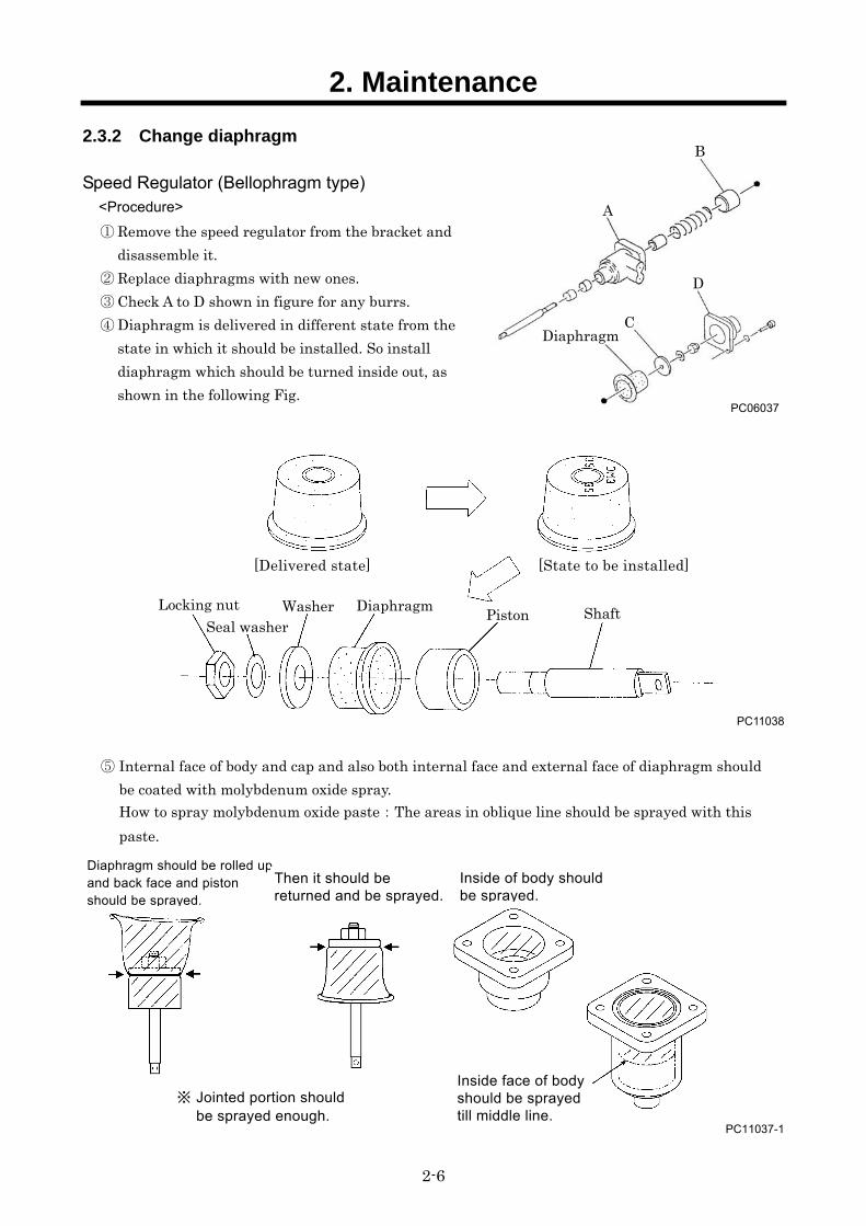
2.3.2 Change diaphragm
Speed Regulator (Bellophragm type) <Procedure>
① Remove the speed regulator from the bracket and disassemble it.
② Replace diaphragms with new ones. ③ Check A to D shown in figure for any burrs. ④ Diaphragm is delivered in different state from the
state in which it should be installed. So install diaphragm which should be turned inside out, as shown in the following Fig.
PC11038
⑤ Internal face of body and cap and also both internal face and external face of diaphragm should be coated with molybdenum oxide spray. How to spray molybdenum oxide paste:The areas in oblique line should be sprayed with this paste.
PC11037-1
B
Shaft Piston Seal washer
Locking nut Washer Diaphragm
[Delivered state] [State to be installed]
PC06037
A
D
Diaphragm C
Diaphragm should be rolled up and back face and piston should be sprayed.
Then it should be returned and be sprayed.
Inside of body should be sprayed.
※ Jointed portion should be sprayed enough.
Inside face of body should be sprayed till middle line.
2. Maintenance
2-7
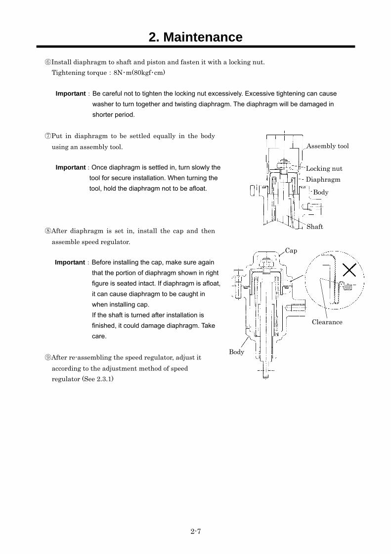
⑥Install diaphragm to shaft and piston and fasten it with a locking nut. Tightening torque:8N・m(80kgf・cm)
Important:Be careful not to tighten the locking nut excessively. Excessive tightening can cause
washer to turn together and twisting diaphragm. The diaphragm will be damaged in
shorter period.
⑦Put in diaphragm to be settled equally in the body using an assembly tool.
Important:Once diaphragm is settled in, turn slowly the
tool for secure installation. When turning the
tool, hold the diaphragm not to be afloat.
⑧After diaphragm is set in, install the cap and then assemble speed regulator.
Important:Before installing the cap, make sure again
that the portion of diaphragm shown in right
figure is seated intact. If diaphragm is afloat,
it can cause diaphragm to be caught in
when installing cap.
If the shaft is turned after installation is
finished, it could damage diaphragm. Take
care.
⑨After re-assembling the speed regulator, adjust it according to the adjustment method of speed regulator (See 2.3.1)
Locking nut Diaphragm
Shaft
Body
Body
Cap
Assembly tool
Clearance
2. Maintenance
2-8
A100179
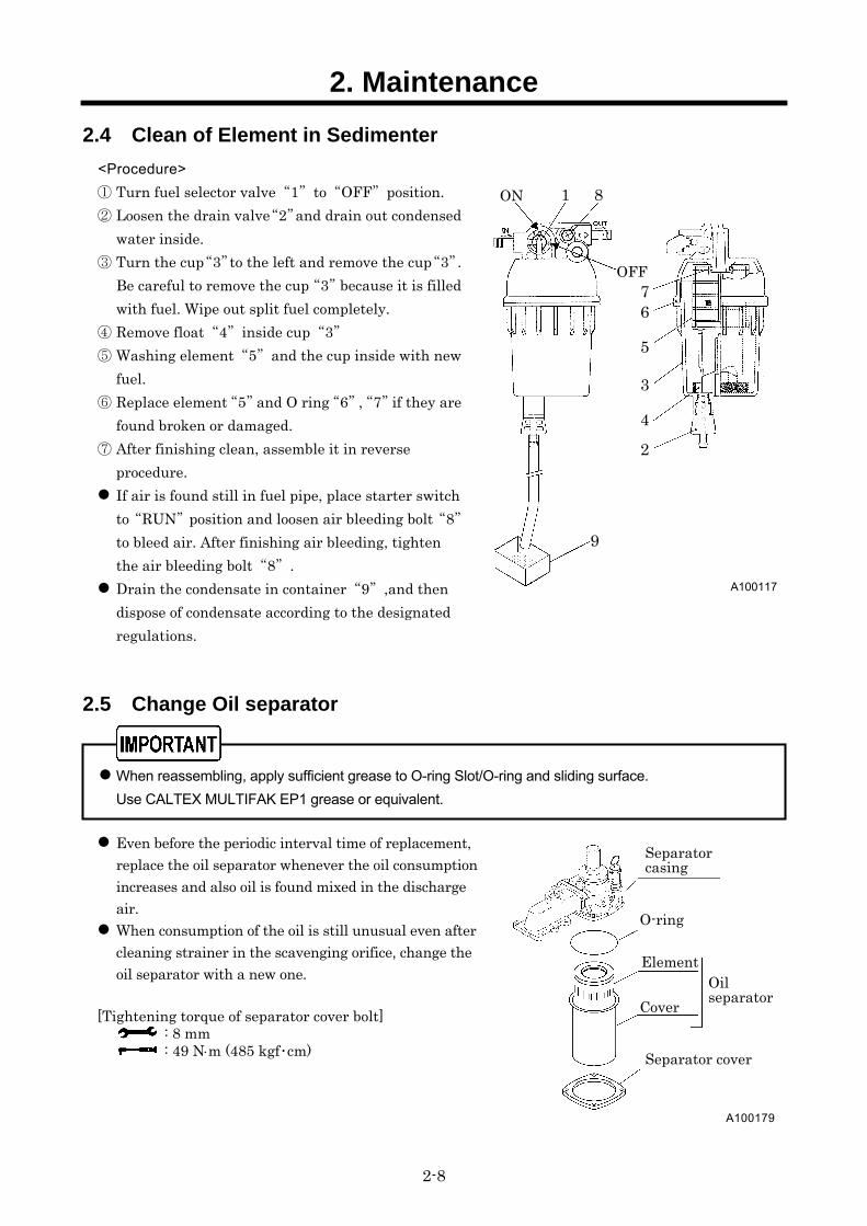
2.4 Clean of Element in Sedimenter <Procedure>
① Turn fuel selector valve“1”to“OFF”position. ② Loosen the drain valve“2”and drain out condensed
water inside. ③ Turn the cup“3”to the left and remove the cup“3”.
Be careful to remove the cup“3”because it is filled with fuel. Wipe out split fuel completely.
④ Remove float“4”inside cup“3” ⑤ Washing element“5”and the cup inside with new
fuel. ⑥ Replace element“5”and O ring“6”,“7”if they are
found broken or damaged. ⑦ After finishing clean, assemble it in reverse
procedure. If air is found still in fuel pipe, place starter switch
to“RUN”position and loosen air bleeding bolt“8”to bleed air. After finishing air bleeding, tighten the air bleeding bolt“8”.
Drain the condensate in container“9”,and then dispose of condensate according to the designated regulations.
2.5 Change Oil separator When reassembling, apply sufficient grease to O-ring Slot/O-ring and sliding surface.
Use CALTEX MULTIFAK EP1 grease or equivalent. Even before the periodic interval time of replacement,
replace the oil separator whenever the oil consumption increases and also oil is found mixed in the discharge air.
When consumption of the oil is still unusual even after cleaning strainer in the scavenging orifice, change the oil separator with a new one.
[Tightening torque of separator cover bolt]
: 8 mm : 49 Nm (485 kgf・cm)
A100117
1 8
76
5
3
42
9
ON
OFF
Cover
O-ring
Separator casing
Oilseparator
Separator cover
Element
2. Maintenance
2-9
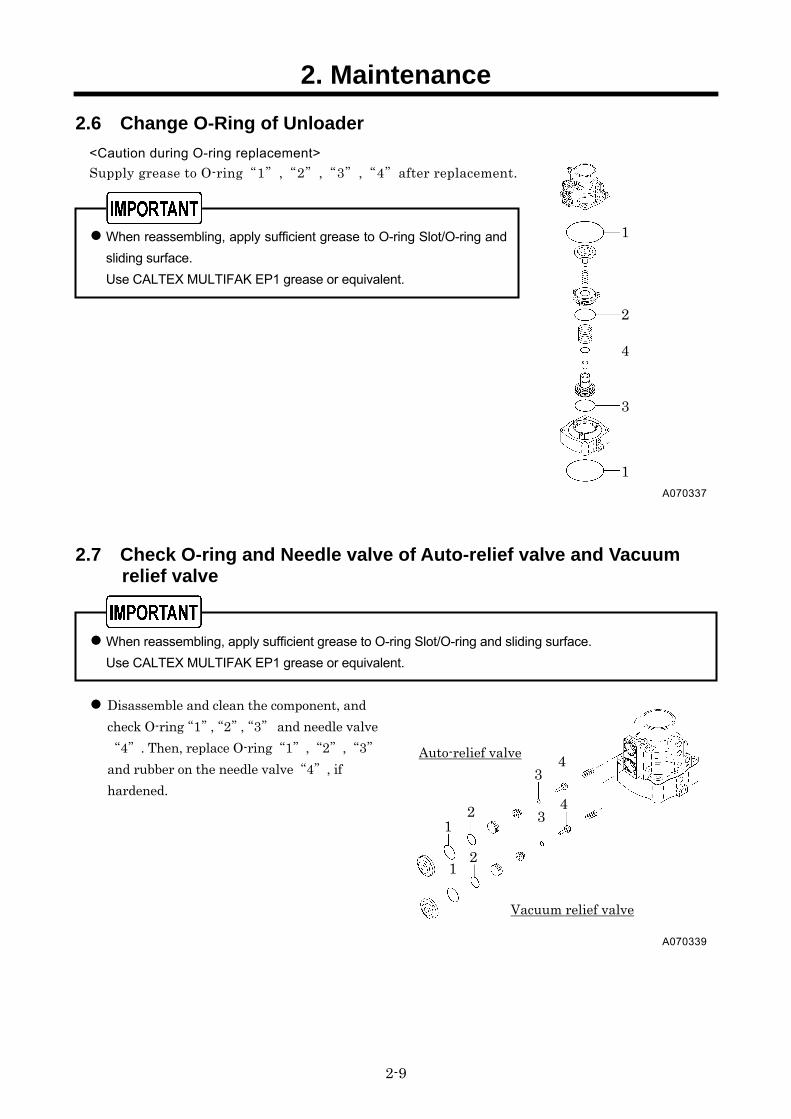
2.6 Change O-Ring of Unloader <Caution during O-ring replacement>
Supply grease to O-ring“1”,“2”,“3”,“4”after replacement.
When reassembling, apply sufficient grease to O-ring Slot/O-ring and
sliding surface.
Use CALTEX MULTIFAK EP1 grease or equivalent.
2.7 Check O-ring and Needle valve of Auto-relief valve and Vacuum relief valve
When reassembling, apply sufficient grease to O-ring Slot/O-ring and sliding surface.
Use CALTEX MULTIFAK EP1 grease or equivalent. Disassemble and clean the component, and
check O-ring“1”,“2”,“3” and needle valve“4”. Then, replace O-ring“1”,“2”,“3”and rubber on the needle valve“4”, if hardened.
A070337
1 2 4 3
1
A070339
12
4 Auto-relief valve
Vacuum relief valve
3
12
4 3
2. Maintenance
2-10
A100180
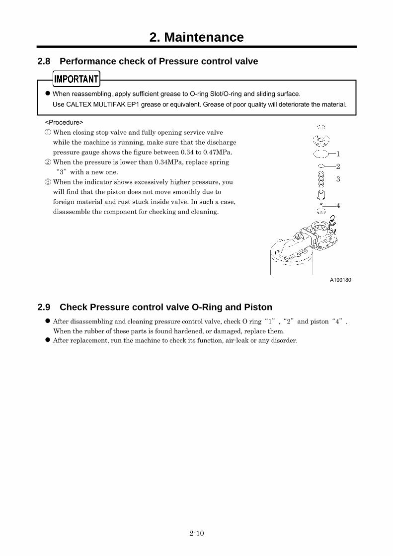
2.8 Performance check of Pressure control valve When reassembling, apply sufficient grease to O-ring Slot/O-ring and sliding surface.
Use CALTEX MULTIFAK EP1 grease or equivalent. Grease of poor quality will deteriorate the material.
<Procedure> ① When closing stop valve and fully opening service valve
while the machine is running, make sure that the discharge pressure gauge shows the figure between 0.34 to 0.47MPa.
② When the pressure is lower than 0.34MPa, replace spring“3”with a new one.
③ When the indicator shows excessively higher pressure, you will find that the piston does not move smoothly due to foreign material and rust stuck inside valve. In such a case, disassemble the component for checking and cleaning.
2.9 Check Pressure control valve O-Ring and Piston After disassembling and cleaning pressure control valve, check O ring“1”,“2”and piston“4”.
When the rubber of these parts is found hardened, or damaged, replace them. After replacement, run the machine to check its function, air-leak or any disorder.
123 4
2. Maintenance
2-11
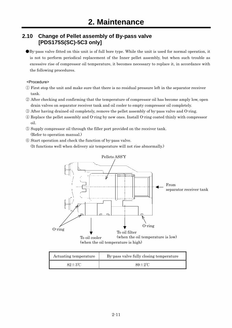
2.10 Change of Pellet assembly of By-pass valve [PDS175S(SC)-5C3 only]
By-pass valve fitted on this unit is of full bore type. While the unit is used for normal operation, it is not to perform periodical replacement of the Inner pellet assembly, but when such trouble as excessive rise of compressor oil temperature, it becomes necessary to replace it, in accordance with the following procedures.
<Procedure>
① First stop the unit and make sure that there is no residual pressure left in the separator receiver tank.
② After checking and confirming that the temperature of compressor oil has become amply low, open drain valves on separator receiver tank and oil cooler to empty compressor oil completely.
③ After having drained oil completely, remove the pellet assembly of by-pass valve and O-ring. ④ Replace the pellet assembly and O-ring by new ones. Install O-ring coated thinly with compressor
oil. ⑤ Supply compressor oil through the filler port provided on the receiver tank.
(Refer to operation manual.) ⑥ Start operation and check the function of by-pass valve.
(It functions well when delivery air temperature will not rise abnormally.)
Actuating temperature By-pass valve fully closing temperature
82±3 89±2
To oil filter (when the oil temperature is low)
O-ring
Pellets ASS’Y
From separator receiver tank
To oil cooler (when the oil temperature is high)
O-ring
2. Maintenance
2-12
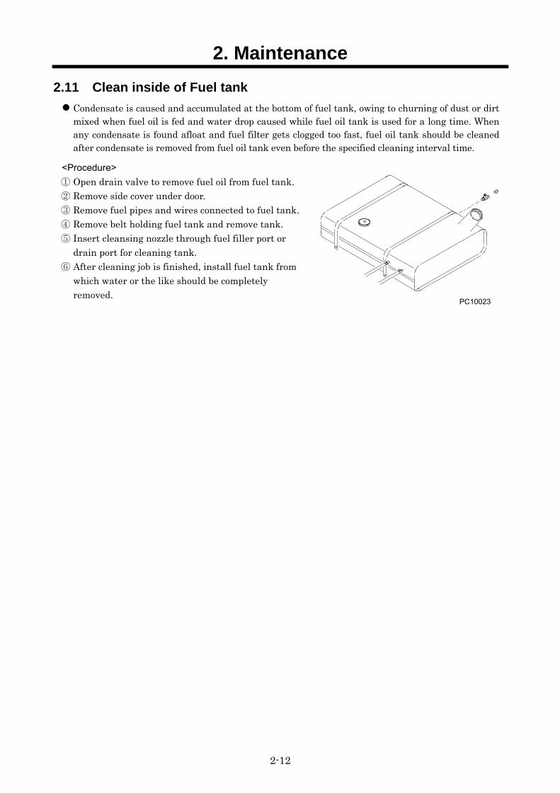
2.11 Clean inside of Fuel tank Condensate is caused and accumulated at the bottom of fuel tank, owing to churning of dust or dirt
mixed when fuel oil is fed and water drop caused while fuel oil tank is used for a long time. When any condensate is found afloat and fuel filter gets clogged too fast, fuel oil tank should be cleaned after condensate is removed from fuel oil tank even before the specified cleaning interval time.
<Procedure>
① Open drain valve to remove fuel oil from fuel tank. ② Remove side cover under door. ③ Remove fuel pipes and wires connected to fuel tank. ④ Remove belt holding fuel tank and remove tank. ⑤ Insert cleansing nozzle through fuel filler port or
drain port for cleaning tank. ⑥ After cleaning job is finished, install fuel tank from
which water or the like should be completely removed.
PC10023
2. Maintenance
2-13
2.12 Values of Various Adjustments of Engine Item Unit PDS130S[SC]-5C3
Engine model YANMAR 3TNV88-BDHK First time 41.1 to 46.9 Tightening torque of head bolts N・m Second time 85.3 to 91.1
Air intake mm 0.20±0.05 (when engine is cold) Valve clearance Discharge mm 0.20±0.05 (when engine is cold) Firing order 1-3-2-1 (No.1 cylinder at flywheel side) Injection timing (BTDC) ° FIT 13.5 (at lift 2.5mm) Nozzle injection pressure MPa 21.6[0,+0.1]
Standard MPa 3.43±0.1 Limited value 2.75±0.1 Compression
(at 250min-1) Working limit MPa Each cylinder limit value Not specified Temperature for start of release 71±1.5
Full open temperature 85 Thermostat
Valve lift mm More than 8.0
Item Unit PDS175S[SC]-5C3 Engine model YANMAR 4TNV88-BDHKS
First time 41.1 to 46.9 Tightening torque of head bolts N・m Second time 85.3 to 91.1 Air intake mm 0.20±0.05 (when engine is cold) Valve
clearance Discharge mm 0.20±0.05 (when engine is cold) Firing order 1-3-4-2-1 (No.1 cylinder at flywheel side) Injection timing (BTDC) ° FIT 13.5 (at lift 2.5mm) Nozzle injection pressure MPa 21.6[0,+0.1]
Standard MPa 3.43±0.1 Limited value 2.75±0.1 Compression
(at 250min-1) Working limit MPa Each cylinder limit value Not specified Temperature for start of release 71±1.5
Full open temperature 85 Thermostat
Valve lift mm More than 8.0 ※For the details, see service manual supplied by engine manufacturer.
3. Electric System
3-1
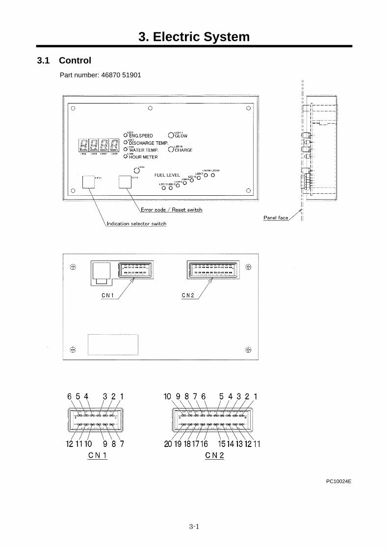
3.1 Control Part number: 46870 51901
PC10024E
3. Electric System
3-2
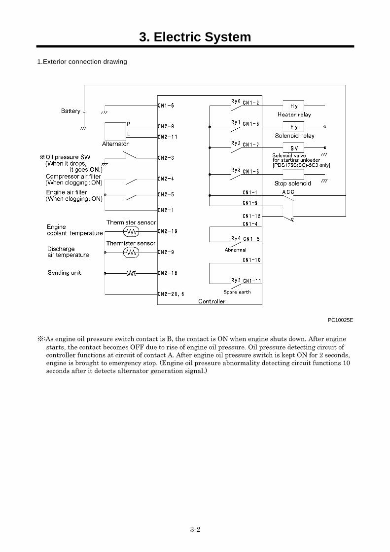
1.Exterior connection drawing
PC10025E
※:As engine oil pressure switch contact is B, the contact is ON when engine shuts down. After engine starts, the contact becomes OFF due to rise of engine oil pressure. Oil pressure detecting circuit of controller functions at circuit of contact A. After engine oil pressure switch is kept ON for 2 seconds, engine is brought to emergency stop. (Engine oil pressure abnormality detecting circuit functions 10 seconds after it detects alternator generation signal.)
3. Electric System
3-3
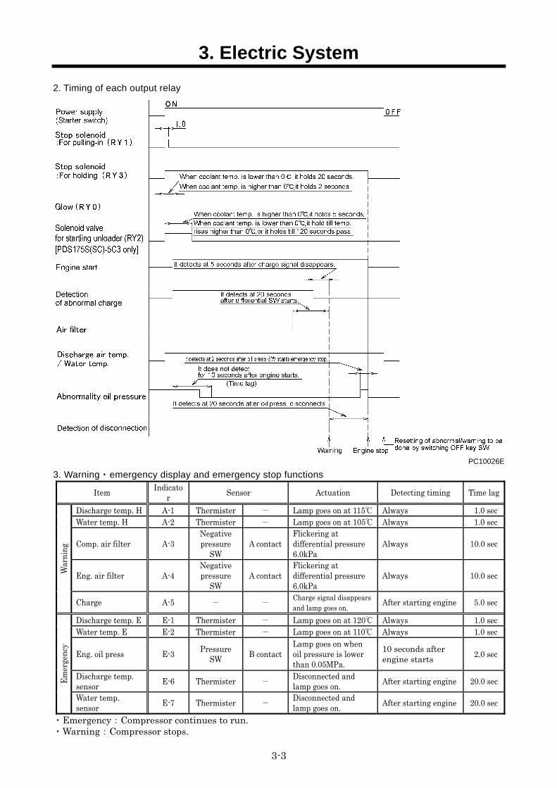
2. Timing of each output relay
PC10026E
3. Warning・emergency display and emergency stop functions
Item Indicato
r Sensor Actuation Detecting timing Time lag
Discharge temp. H A-1 Thermister - Lamp goes on at 115 Always 1.0 sec Water temp. H A-2 Thermister - Lamp goes on at 105 Always 1.0 sec
Comp. air filter A-3 Negative pressure
SW A contact
Flickering at differential pressure 6.0kPa
Always 10.0 sec
Eng. air filter A-4 Negative pressure
SW A contact
Flickering at differential pressure 6.0kPa
Always 10.0 sec War
ning
Charge A-5 - - Charge signal disappears and lamp goes on.
After starting engine 5.0 sec
Discharge temp. E E-1 Thermister - Lamp goes on at 120 Always 1.0 sec Water temp. E E-2 Thermister - Lamp goes on at 110 Always 1.0 sec
Eng. oil press E-3 Pressure
SW B contact
Lamp goes on when oil pressure is lower than 0.05MPa.
10 seconds after engine starts
2.0 sec
Discharge temp. sensor
E-6 Thermister - Disconnected and lamp goes on.
After starting engine 20.0 sec Em
erge
ncy
Water temp. sensor
E-7 Thermister - Disconnected and lamp goes on.
After starting engine 20.0 sec
・Emergency:Compressor continues to run. ・Warning:Compressor stops.
3. Electric System
3-4
PC10027E
4. Functions of each output relay
Mark Name Remark
RY0 Relay for heater relay It goes ON when starter SW is ON.
When coolant temp. is lower than 0、it becomes OFF 20 seconds later.When coolant temp. is higher than 0, it becomes OFF 2 seconds later.
RY1 Relay for solenoid relay It goes ON for 1 second when starter SW is ON.
RY2 Relay for starting unloader [PDS175S(SC)-5C3 only]
It goes ON when starter SW is ON.
When coolant temp. is lower than 0, or when 120 seconds pass, it becomes OFF. When coolant temp. is higher than 0, it becomes OFF 5 seconds later.
RY3 Relay for solenoid It goes ON when starter SW is ON.
RY4 Abnormality output relay
RY5 Spare output relay
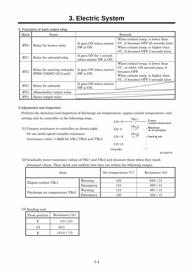
5.Adjustment and inspection
Perform the detection and inspection of discharge air temperature, engine coolant temperature, and setting unit by controller in the following steps.
(1) Connect resistance to controller as shown right. Or use multi-speed variable resistance (resistance value: 1.0kΩ) for VRc1,VRc2 and VRc3.
(2) Gradually lower resistance values of VRc1 and VRc2 and measure them when they reach abnormal values. Then check and confirm that they are within the following ranges.
Item Set temperature () Resistance (Ω)
Warning 105 640±15 Engine coolant VRc1 Emergency 110 560±15 Warning 115 491±15 Discharge air temperature VRc2 Emergency 120 432±15
(3) Sending unit Float position Resistance (Ω)
F 3.0±2.0 1/2 32.5 E 110.0±7.0
3. Electric System
3-5
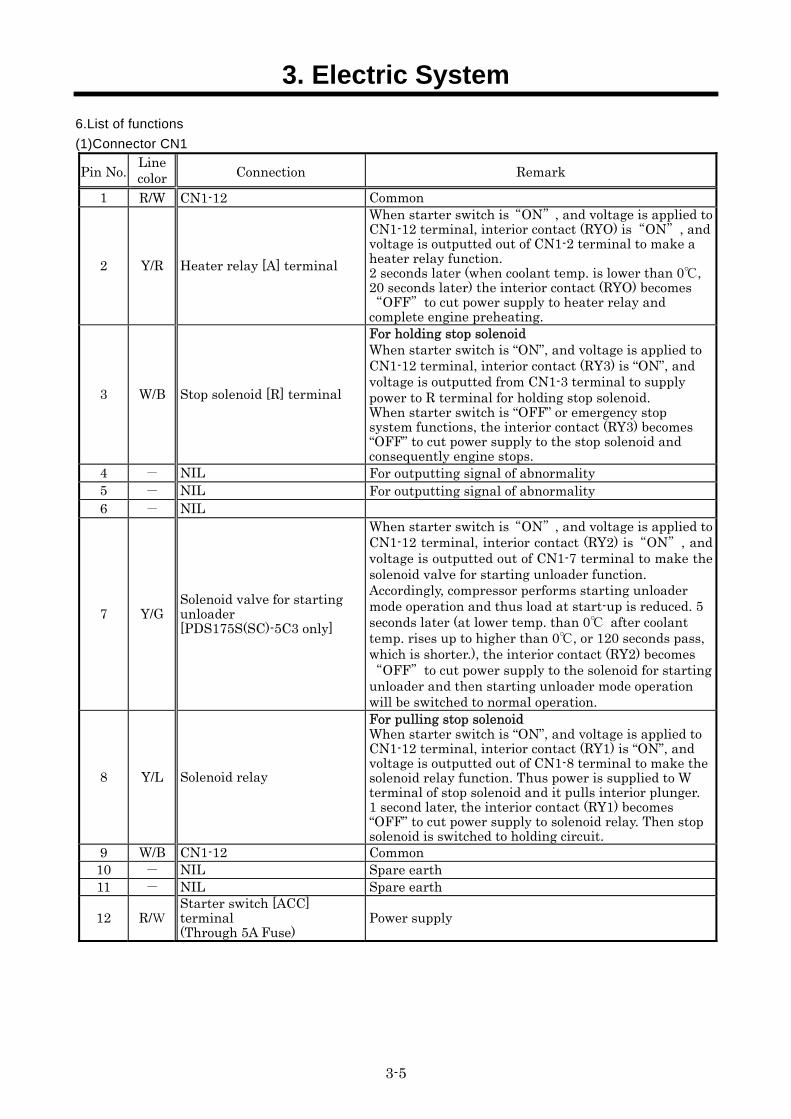
6.List of functions
(1)Connector CN1
Pin No. Line color Connection Remark
1 R/W CN1-12 Common
2 Y/R Heater relay [A] terminal
When starter switch is“ON”, and voltage is applied to CN1-12 terminal, interior contact (RYO) is“ON”, and voltage is outputted out of CN1-2 terminal to make a heater relay function. 2 seconds later (when coolant temp. is lower than 0, 20 seconds later) the interior contact (RYO) becomes “OFF”to cut power supply to heater relay and complete engine preheating.
3 W/B Stop solenoid [R] terminal
For holding stop solenoid When starter switch is “ON”, and voltage is applied to CN1-12 terminal, interior contact (RY3) is “ON”, and voltage is outputted from CN1-3 terminal to supply power to R terminal for holding stop solenoid. When starter switch is “OFF” or emergency stop system functions, the interior contact (RY3) becomes “OFF” to cut power supply to the stop solenoid and consequently engine stops.
4 - NIL For outputting signal of abnormality 5 - NIL For outputting signal of abnormality 6 - NIL
7 Y/G Solenoid valve for starting unloader [PDS175S(SC)-5C3 only]
When starter switch is“ON”, and voltage is applied to CN1-12 terminal, interior contact (RY2) is“ON”, and voltage is outputted out of CN1-7 terminal to make the solenoid valve for starting unloader function. Accordingly, compressor performs starting unloader mode operation and thus load at start-up is reduced. 5 seconds later (at lower temp. than 0 after coolant temp. rises up to higher than 0, or 120 seconds pass, which is shorter.), the interior contact (RY2) becomes “OFF”to cut power supply to the solenoid for starting unloader and then starting unloader mode operation will be switched to normal operation.
8 Y/L Solenoid relay
For pulling stop solenoid When starter switch is “ON”, and voltage is applied to CN1-12 terminal, interior contact (RY1) is “ON”, and voltage is outputted out of CN1-8 terminal to make the solenoid relay function. Thus power is supplied to W terminal of stop solenoid and it pulls interior plunger. 1 second later, the interior contact (RY1) becomes “OFF” to cut power supply to solenoid relay. Then stop solenoid is switched to holding circuit.
9 W/B CN1-12 Common 10 - NIL Spare earth 11 - NIL Spare earth
12 R/W Starter switch [ACC] terminal (Through 5A Fuse)
Power supply
3. Electric System
3-6
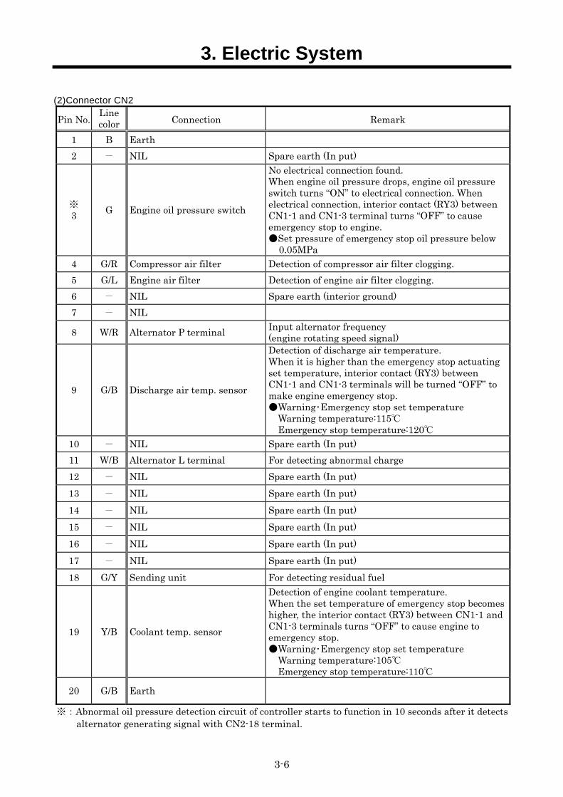
(2)Connector CN2
Pin No. Line color Connection Remark
1 B Earth 2 - NIL Spare earth (In put)
※ 3 G Engine oil pressure switch
No electrical connection found. When engine oil pressure drops, engine oil pressure switch turns “ON” to electrical connection. When electrical connection, interior contact (RY3) between CN1-1 and CN1-3 terminal turns “OFF” to cause emergency stop to engine. Set pressure of emergency stop oil pressure below
0.05MPa 4 G/R Compressor air filter Detection of compressor air filter clogging. 5 G/L Engine air filter Detection of engine air filter clogging. 6 - NIL Spare earth (interior ground) 7 - NIL
8 W/R Alternator P terminal Input alternator frequency (engine rotating speed signal)
9 G/B Discharge air temp. sensor
Detection of discharge air temperature. When it is higher than the emergency stop actuating set temperature, interior contact (RY3) between CN1-1 and CN1-3 terminals will be turned “OFF” to make engine emergency stop. Warning・Emergency stop set temperature Warning temperature:115
Emergency stop temperature:120
10 - NIL Spare earth (In put) 11 W/B Alternator L terminal For detecting abnormal charge 12 - NIL Spare earth (In put) 13 - NIL Spare earth (In put) 14 - NIL Spare earth (In put) 15 - NIL Spare earth (In put) 16 - NIL Spare earth (In put) 17 - NIL Spare earth (In put) 18 G/Y Sending unit For detecting residual fuel
19 Y/B Coolant temp. sensor
Detection of engine coolant temperature. When the set temperature of emergency stop becomes higher, the interior contact (RY3) between CN1-1 and CN1-3 terminals turns “OFF” to cause engine to emergency stop. Warning・Emergency stop set temperature Warning temperature:105
Emergency stop temperature:110
20 G/B Earth
※:Abnormal oil pressure detection circuit of controller starts to function in 10 seconds after it detects alternator generating signal with CN2-18 terminal.
3. Electric System
3-7
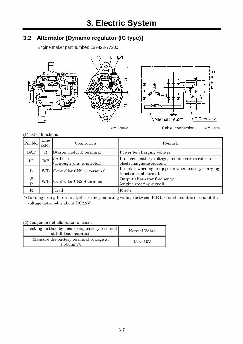
3.2 Alternator [Dynamo regulator (IC type)] Engine maker part number: 129423-77200
PC10028E-1 Cable connection PC10057E
(1)List of functions
Pin No. Line color Connection Remark
BAT R Starter motor B terminal Power for charging voltage.
IG R/B 5A Fuse (Through joint connector)
It detects battery voltage, and it controls rotor coil electromagnetic current.
L W/B Controller CN2-11 terminal It makes warning lamp go on when battery charging function is abnormal.
※ P W/R Controller CN2-8 terminal Output alternator frequency
(engine rotating signal) E - Earth Earth
※For diagnosing P terminal, check the generating voltage between P-E terminal and it is normal if the voltage detected is about DC2.2V.
(2) Judgement of alternator functions
Checking method by measuring battery terminalat full load operation Normal Value
Measure the battery terminal voltage at 1,500min-1. 13 to 15V
3. Electric System
3-8
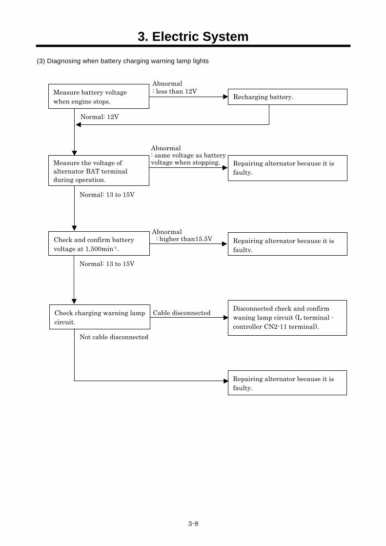
(3) Diagnosing when battery charging warning lamp lights
Abnormal : less than 12V
Recharging battery.
Repairing alternator because it is faulty.
Normal: 13 to 15V
Abnormal : same voltage as battery voltage when stopping.
Repairing alternator because it is faulty.
Normal: 13 to 15V
Abnormal : higher than15.5V
Check charging warning lamp circuit.
Disconnected check and confirm waning lamp circuit (L terminal - controller CN2-11 terminal).
Cable disconnected
Repairing alternator because it is faulty.
Not cable disconnected
Normal: 12V
Measure the voltage of alternator BAT terminal during operation.
Check and confirm battery voltage at 1,500min-1.
Measure battery voltage when engine stops.
3. Electric System
3-9
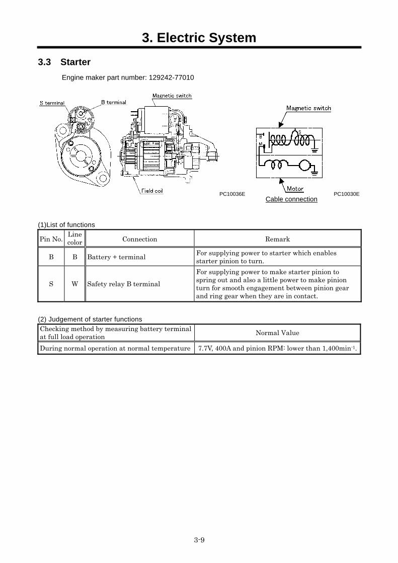
3.3 Starter Engine maker part number: 129242-77010
PC10036E PC10030E
(1)List of functions
Pin No. Line color Connection Remark
B B Battery + terminal For supplying power to starter which enables starter pinion to turn.
S W Safety relay B terminal For supplying power to make starter pinion to spring out and also a little power to make pinion turn for smooth engagement between pinion gear and ring gear when they are in contact.
(2) Judgement of starter functions
Checking method by measuring battery terminalat full load operation Normal Value
During normal operation at normal temperature 7.7V, 400A and pinion RPM: lower than 1,400min-1.
Cable connection
3. Electric System
3-10
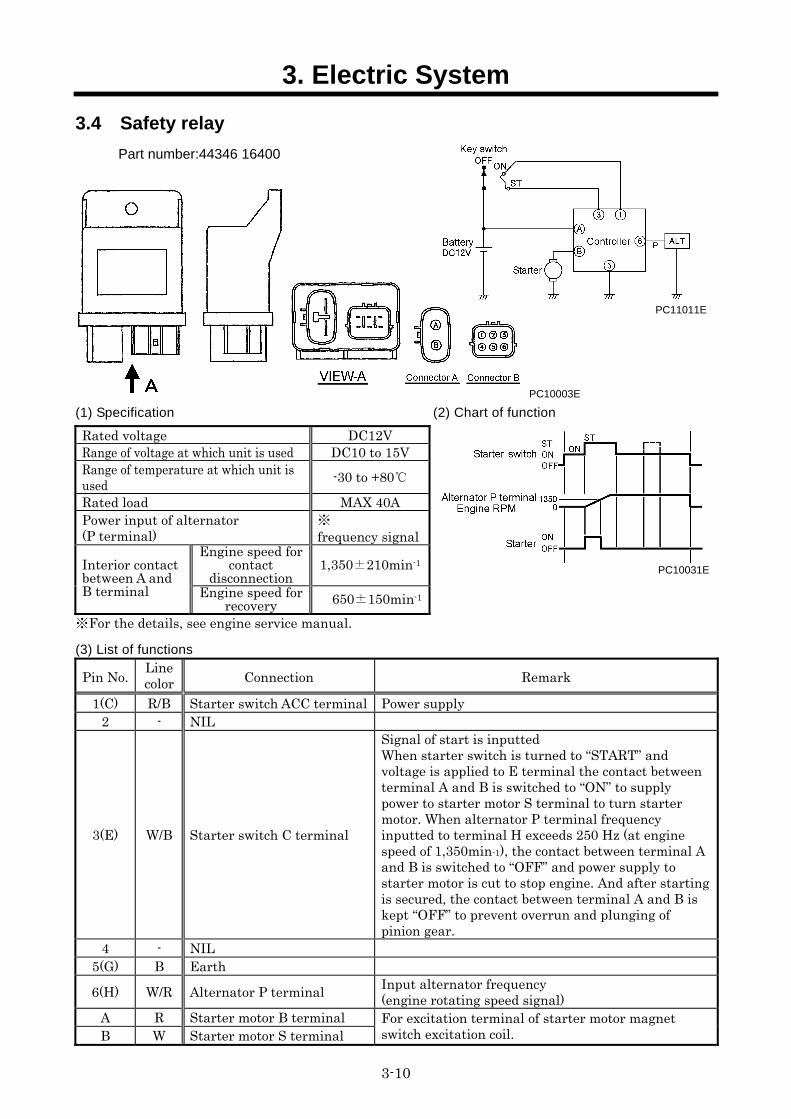
3.4 Safety relay Part number:44346 16400
PC10003E
(1) Specification (2) Chart of function
Rated voltage DC12V Range of voltage at which unit is used DC10 to 15V Range of temperature at which unit is used -30 to +80
Rated load MAX 40A Power input of alternator (P terminal)
※ frequency signal
Engine speed for contact
disconnection 1,350±210min-1Interior contact
between A and B terminal Engine speed for
recovery 650±150min-1
※For the details, see engine service manual.
(3) List of functions
Pin No. Line color Connection Remark
1(C) R/B Starter switch ACC terminal Power supply 2 - NIL
3(E) W/B Starter switch C terminal
Signal of start is inputted When starter switch is turned to “START” and voltage is applied to E terminal the contact between terminal A and B is switched to “ON” to supply power to starter motor S terminal to turn starter motor. When alternator P terminal frequency inputted to terminal H exceeds 250 Hz (at engine speed of 1,350min-1), the contact between terminal A and B is switched to “OFF” and power supply to starter motor is cut to stop engine. And after starting is secured, the contact between terminal A and B is kept “OFF” to prevent overrun and plunging of pinion gear.
4 - NIL 5(G) B Earth
6(H) W/R Alternator P terminal Input alternator frequency (engine rotating speed signal)
A R Starter motor B terminal B W Starter motor S terminal
For excitation terminal of starter motor magnet switch excitation coil.
PC11011E
PC10031E
3. Electric System
3-11
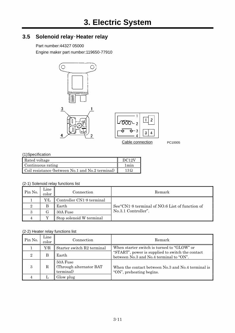
3.5 Solenoid relay・Heater relay Part number:44327 05000
Engine maker part number:119650-77910
PC10005
(1)Specification
Rated voltage DC12V Continuous rating 1min Coil resistance (between No.1 and No.2 terminal) 13Ω
(2-1) Solenoid relay functions list
Pin No. Line color Connection Remark
1 Y/L Controller CN1-8 terminal 2 B Earth 3 G 30A Fuse 4 Y Stop solenoid W terminal
See“CN1-8 terminal of NO.6 List of function of No.3.1 Controller”.
(2-2) Heater relay functions list
Pin No. Line color Connection Remark
1 Y/R Starter switch R2 terminal 2 B Earth
When starter switch is turned to “GLOW” or “START”, power is supplied to switch the contact between No.3 and No.4 terminal to “ON”.
3 R 50A Fuse (Through alternator BAT terminal)
4 L Glow plug
When the contact between No.3 and No.4 terminal is “ON”, preheating begins.
Cable connection
3. Electric System
3-12
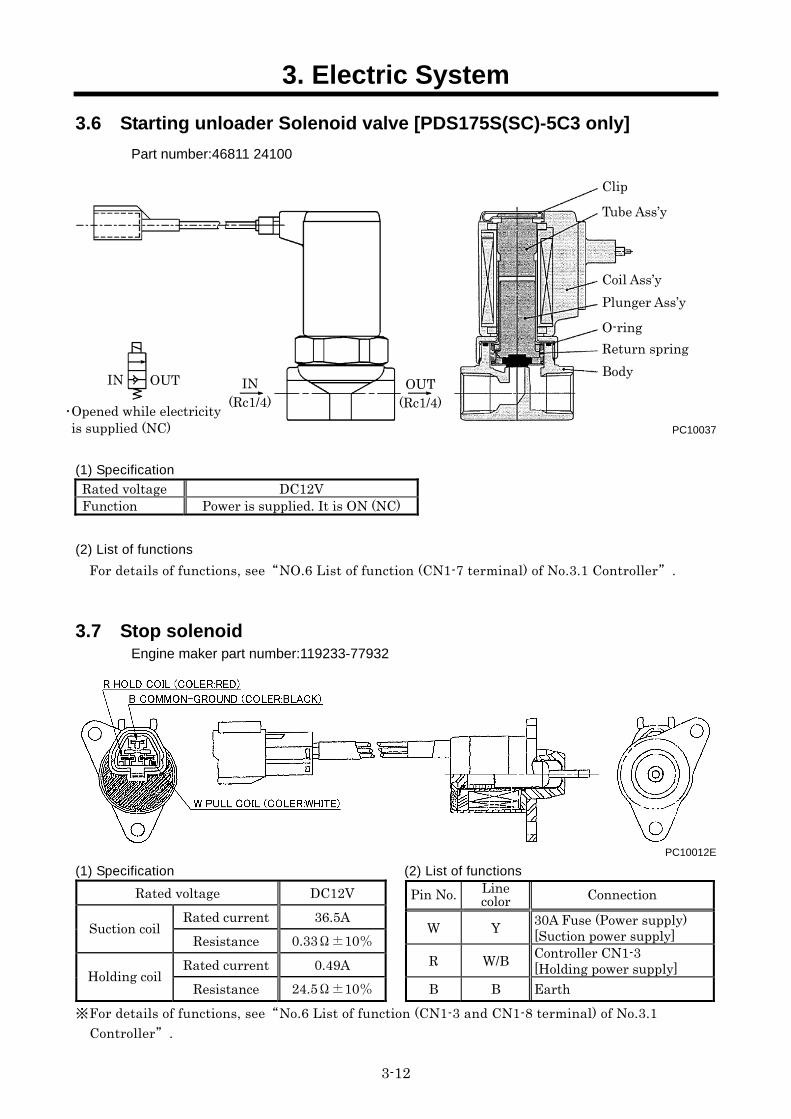
3.6 Starting unloader Solenoid valve [PDS175S(SC)-5C3 only] Part number:46811 24100
PC10037
(1) Specification
Rated voltage DC12V Function Power is supplied. It is ON (NC)
(2) List of functions
For details of functions, see“NO.6 List of function (CN1-7 terminal) of No.3.1 Controller”.
3.7 Stop solenoid Engine maker part number:119233-77932
PC10012E
(1) Specification (2) List of functions
Rated voltage DC12V Rated current 36.5A
Suction coil Resistance 0.33Ω±10%
Rated current 0.49A Holding coil
Resistance 24.5Ω±10%※For details of functions, see“No.6 List of function (CN1-3 and CN1-8 terminal) of No.3.1
Controller”.
OUT IN
・Opened while electricity is supplied (NC)
IN (Rc1/4)
OUT (Rc1/4)
Clip
Tube Ass’y
Coil Ass’y Plunger Ass’y
O-ring Return spring Body
Pin No. Line color Connection
W Y 30A Fuse (Power supply) [Suction power supply]
R W/B Controller CN1-3 [Holding power supply]
B B Earth
3. Electric System
3-13
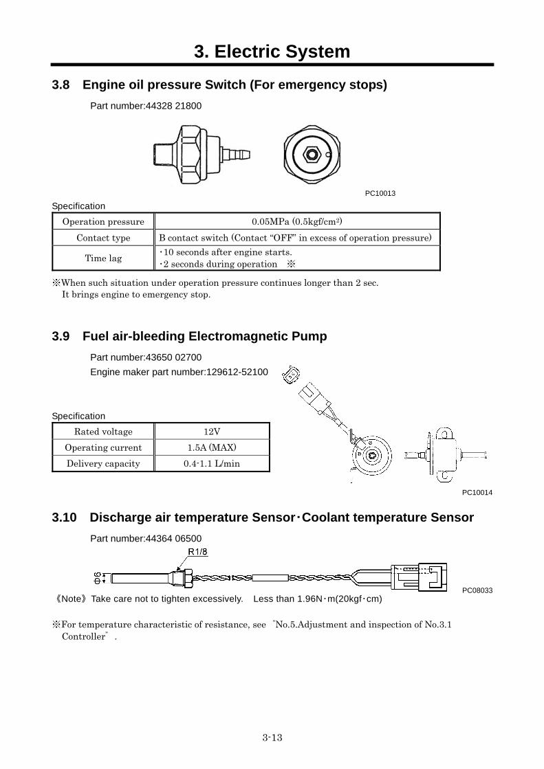
3.8 Engine oil pressure Switch (For emergency stops) Part number:44328 21800
PC10013
Specification
Operation pressure 0.05MPa (0.5kgf/cm2) Contact type B contact switch (Contact “OFF” in excess of operation pressure)
Time lag ・10 seconds after engine starts. ・2 seconds during operation ※
※When such situation under operation pressure continues longer than 2 sec. It brings engine to emergency stop.
3.9 Fuel air-bleeding Electromagnetic Pump
Part number:43650 02700
Engine maker part number:129612-52100
Specification
3.10 Discharge air temperature Sensor・Coolant temperature Sensor
Part number:44364 06500
PC08033 《Note》Take care not to tighten excessively. Less than 1.96N・m(20kgf・cm)
※For temperature characteristic of resistance, see“No.5.Adjustment and inspection of No.3.1
Controller”.
Rated voltage 12V Operating current 1.5A (MAX) Delivery capacity 0.4-1.1 L/min
PC10014
3. Electric System
3-14
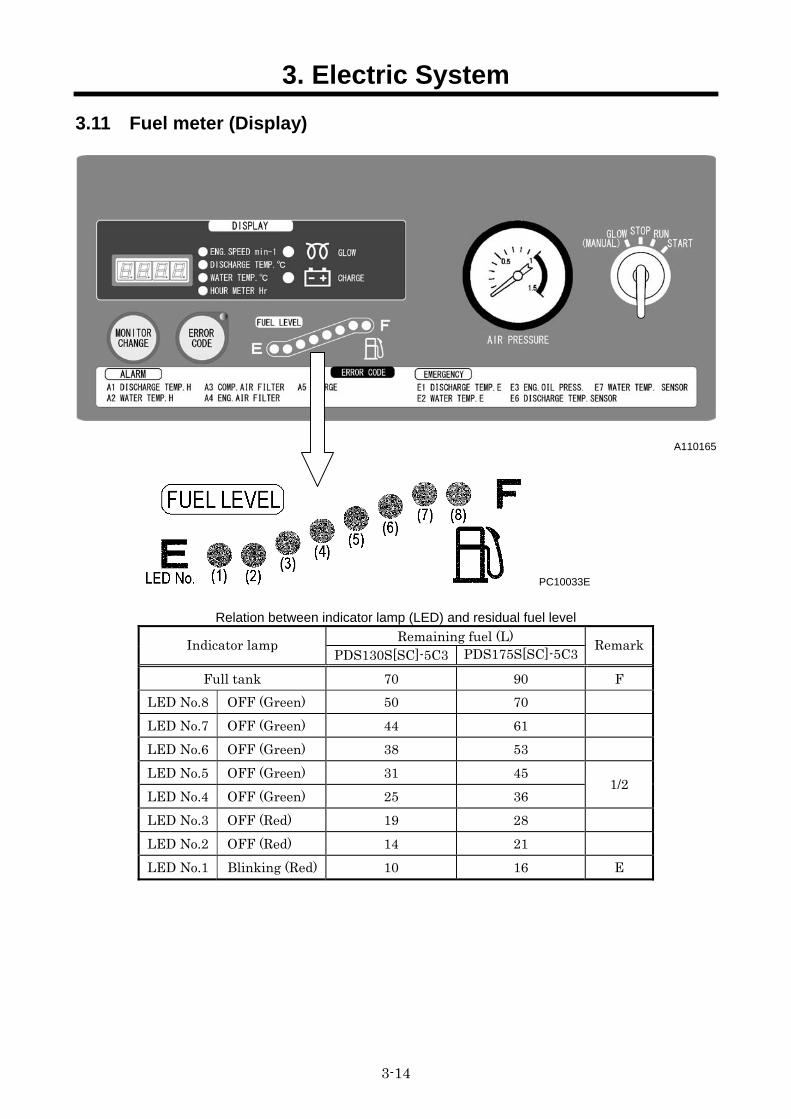
3.11 Fuel meter (Display)
A110165
PC10033E
Relation between indicator lamp (LED) and residual fuel level
Remaining fuel (L) Indicator lamp PDS130S[SC]-5C3 PDS175S[SC]-5C3 Remark
Full tank 70 90 F LED No.8 OFF (Green) 50 70 LED No.7 OFF (Green) 44 61 LED No.6 OFF (Green) 38 53 LED No.5 OFF (Green) 31 45 LED No.4 OFF (Green) 25 36
1/2
LED No.3 OFF (Red) 19 28 LED No.2 OFF (Red) 14 21 LED No.1 Blinking (Red) 10 16 E
3. Electric System
3-15
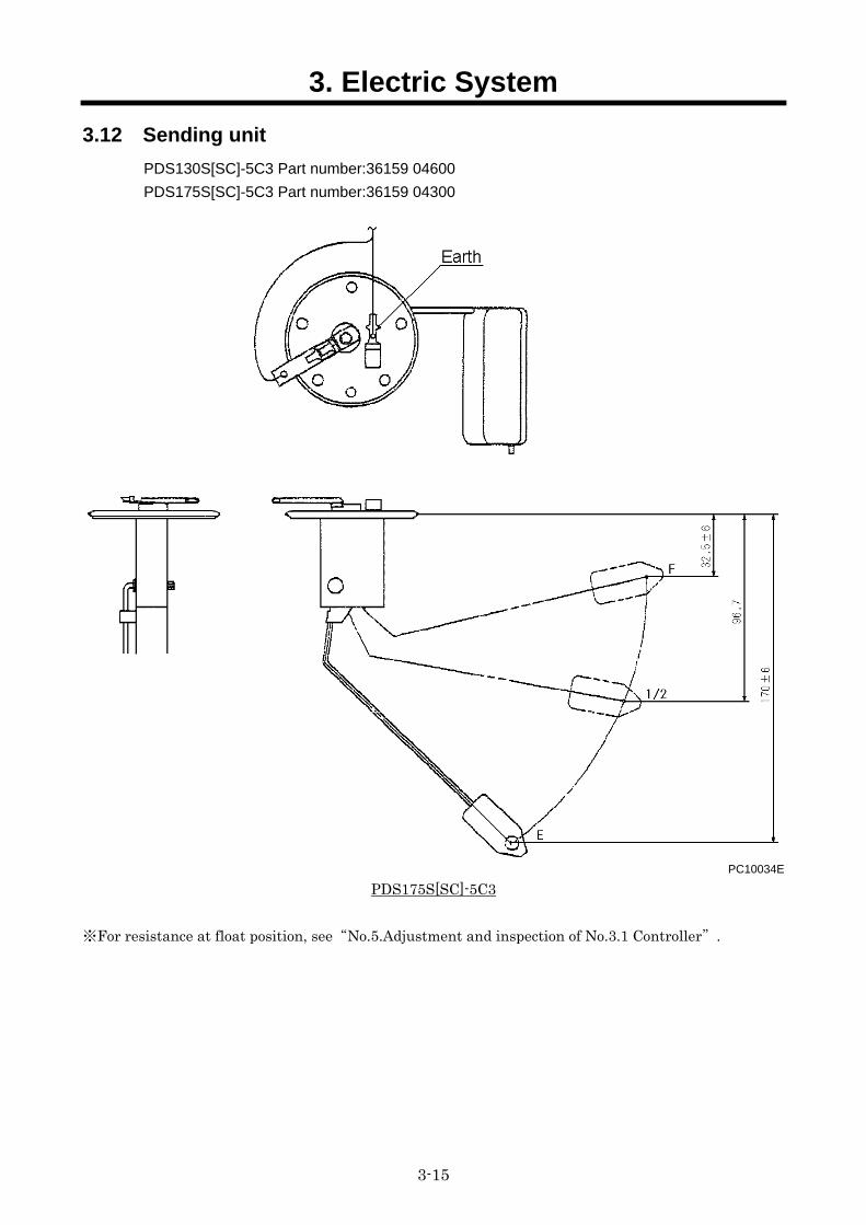
3.12 Sending unit PDS130S[SC]-5C3 Part number:36159 04600
PDS175S[SC]-5C3 Part number:36159 04300
PC10034E
PDS175S[SC]-5C3
※For resistance at float position, see“No.5.Adjustment and inspection of No.3.1 Controller”.
4. Troubleshooting
4-1
4.1 Repairing Procedures When performing failure diagnosis, pay special attention to the followings, observing general cautions.
4.1.1 Safety caution (1) Removing such cap and/or plug for receiver tank, fuel tanks and pipes where pressure is
loaded, stop the machine and relieve all the interior pressure. Install measuring instruments connected firmly.
(2) When doing the job with co-worker(s) together, make sure to give signal to the other person(s) and do not allow other persons to come near to the job site.
(3) Take care not to touch hot portions and not to be involved in turning portions.
4.1.2 Caution during failure diagnosis (1) Do not make haste to disassemble the unit
If the unit is disassembled urgently. ①You may disassemble the other portions which are not related with the trouble. ②The cause of trouble may be missing. The unnecessary reparations require more spare parts and man-hours, and reparation costs will increase more. What is worse, you will lose reliance or trust from clients,operators and users. Therefore, it is absolutely necessary to investigate the trouble more carefully in advance and to follow the required procedures for failure diagnosis.
(2) Ask the clients about the trouble in details In order to prevent misunderstanding and incorrect judgment about the trouble, it is necessary to ask users or operators about the following questions. ①Is there any other disorder than the trouble he has informed? ②Anything abnormal occurred before this trouble? ③Did this trouble happen unexpectedly? Or the unit had been operated in bad conditions before? ④When and how did this trouble occur? ⑤Had he repaired the unit before this trouble occurred? ⑥Did he not experience similar trouble before?
(3) Inspection items before starting diagnosis Sometimes such trouble may be caused owing to routine mishandling of the unit. Before starting failure diagnosis, check the following items. ①The engine runs short of engine oil or its oil is not dirty? ②Check each wire connection for any disconnection. ③Check the other portions for any damage.
(4) Confirmation of trouble
Discuss with user(s) and/or operator(s) sufficiently about the trouble. As a result, judge whether their judgment is based on the numerical comparison or sentimental basis. Make him (them) understand well the reparation or correction you have finished. Then check and confirm by yourself the cause of the trouble. Note) Never proceed any investigation or measurement which may cause further greater damage.
4. Troubleshooting
4-2
(5) Procedures of diagnosis
When you become well experienced, you can find out the cause easily during the process of confirmation (4). But easy understanding could cause unexpected failure. So check and judge it according to the following procedures. ①Check the easiest thing or portion first. ②Investigate the most possible cause. ③Check the other things connected to the trouble. ④Check for the possibility of any other troubles. ⑤Start proper and careful investigation on this trouble.
(6) Prevention of repeated occurrence of similar trouble Even if you have repaired the trouble, unless you get rid of the fundamental cause of the trouble, it will repeatedly occur. Therefore, perform full investigation of the trouble, and it is absolutely necessary to remove the basis of the trouble.
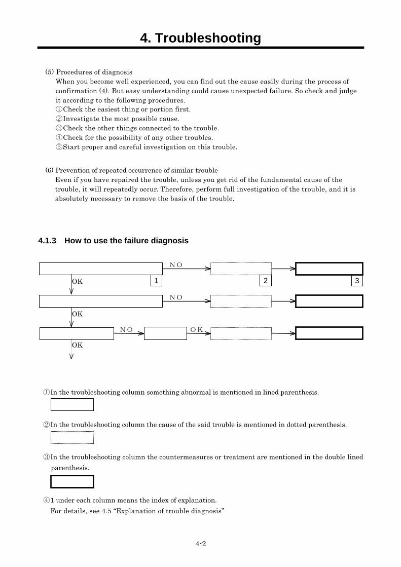
4.1.3 How to use the failure diagnosis
① In the troubleshooting column something abnormal is mentioned in lined parenthesis.
② In the troubleshooting column the cause of the said trouble is mentioned in dotted parenthesis.
③ In the troubleshooting column the countermeasures or treatment are mentioned in the double lined parenthesis.
④ 1 under each column means the index of explanation. For details, see 4.5 “Explanation of trouble diagnosis”
NO
NO
NO
OK
OK
OK
OK
1 2 3
4. Troubleshooting
4-3
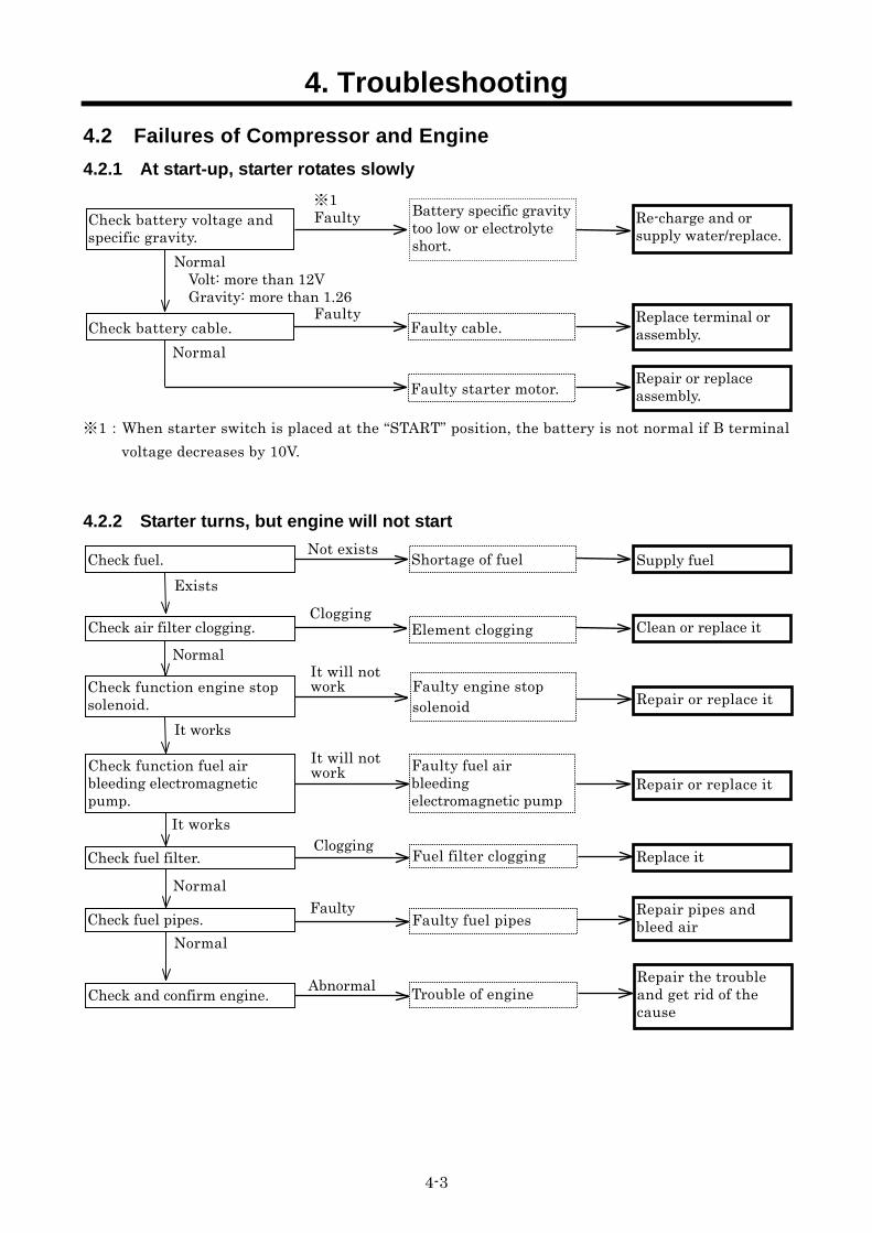
4.2 Failures of Compressor and Engine 4.2.1 At start-up, starter rotates slowly
※1:When starter switch is placed at the “START” position, the battery is not normal if B terminal voltage decreases by 10V.
4.2.2 Starter turns, but engine will not start
Re-charge and or supply water/replace.
Check battery cable. Faulty cable.
Faulty starter motor.
Replace terminal or assembly.
Repair or replace assembly.
Normal Volt: more than 12V Gravity: more than 1.26
※1 Faulty Check battery voltage and
specific gravity.
Faulty
Normal
Battery specific gravity too low or electrolyte short.
Repair or replace it
Shortage of fuel Supply fuel Check fuel. Not exists
Exists
Check function engine stop solenoid.
Check fuel filter. Fuel filter clogging Replace it
Normal
Clogging
Check fuel pipes. Faulty fuel pipes Faulty Repair pipes and
bleed air Normal
Check and confirm engine. Trouble of engine Repair the trouble and get rid of the cause
Abnormal
It works
It will not work
Check function fuel air bleeding electromagnetic pump.
Faulty fuel air bleeding electromagnetic pump
Repair or replace it
It works
It will not work
Normal Element clogging Clean or replace it
Clogging Check air filter clogging.
Faulty engine stop solenoid
4. Troubleshooting
4-4
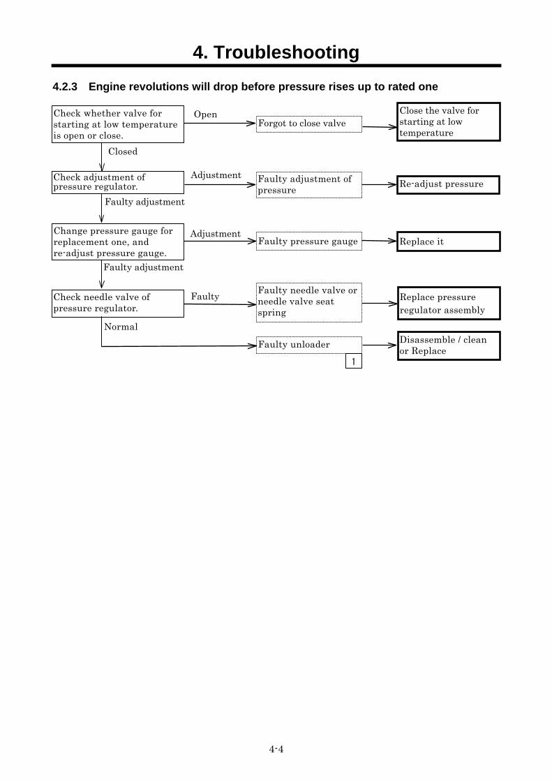
4.2.3 Engine revolutions will drop before pressure rises up to rated one
Faulty adjustment of pressure Re-adjust pressureCheck adjustment of
pressure regulator. Adjustment
Disassemble / clean or Replace
Check needle valve of pressure regulator.
Faulty needle valve or needle valve seat spring
Faulty unloader
Replace pressure regulator assembly
Change pressure gauge for replacement one, and re-adjust pressure gauge.
Faulty pressure gauge
Normal
AdjustmentReplace it
Faulty adjustment
Check whether valve for starting at low temperature is open or close.
Forgot to close valve Open Close the valve for
starting at low temperature
Closed
Faulty adjustment
Faulty
1
4. Troubleshooting
4-5
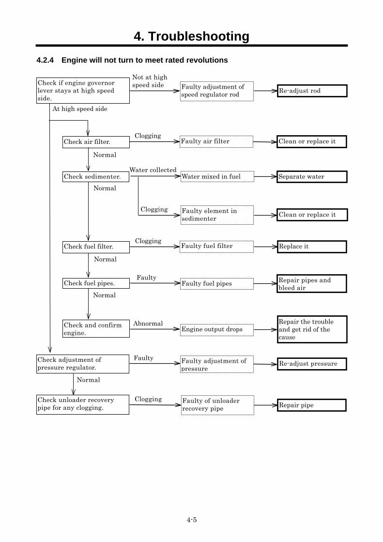
4.2.4 Engine will not turn to meet rated revolutions
Check if engine governor lever stays at high speed side.
Faulty adjustment of speed regulator rod Re-adjust rod
Not at high speed side
At high speed side
Check adjustment of pressure regulator.
Faulty adjustment of pressure
Re-adjust pressure
Check unloader recovery pipe for any clogging.
Faulty of unloader recovery pipe Repair pipe
Clogging
Check and confirm engine. Engine output drops
Repair the trouble and get rid of the cause
Check fuel pipes. Faulty fuel pipes Repair pipes and bleed air
Faulty air filter Clean or replace it Check air filter.
Check fuel filter. Faulty fuel filter Replace it
Clogging
Check sedimenter. Water mixed in fuel Separate water
Faulty element in sedimenter Clean or replace it
Normal
Water collected
Clogging
Normal
Normal
Clogging
Faulty
Normal
Abnormal
Normal
Faulty
4. Troubleshooting
4-6
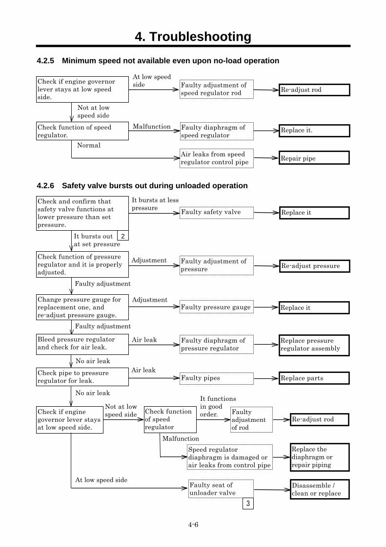
4.2.5 Minimum speed not available even upon no-load operation
4.2.6 Safety valve bursts out during unloaded operation
Faulty adjustment of speed regulator rod Re-adjust rod
Check function of speed regulator.
Faulty diaphragm of speed regulator
Replace it. Malfunction
Air leaks from speed regulator control pipe Repair pipe
Normal
Check if engine governor lever stays at low speed side.
Not at low speed side
At low speedside
It bursts at less pressure
Faulty adjustment of pressure Re-adjust pressure
Adjustment
Change pressure gauge for replacement one, and re-adjust pressure gauge.
Faulty adjustment
AdjustmentReplace it
Faulty adjustment
Faulty safety valve
It bursts out at set pressure
Replace it
Faulty diaphragm of pressure regulator
Air leak
No air leak
2
Replace pressure regulator assembly
Check pipe to pressure regulator for leak. Faulty pipes Replace parts
Air leak
No air leak
Check function of pressure regulator and it is properly adjusted.
Check and confirm that safety valve functions at lower pressure than set pressure.
Faulty pressure gauge
Bleed pressure regulator and check for air leak.
Faulty seat of unloader valve
3
Disassemble / clean or replace
Check if engine governor lever stays at low speed side.
Faulty adjustment of rod
Re-adjust rod Check function of speed regulator
It functions in good order.
MalfunctionSpeed regulator diaphragm is damaged or air leaks from control pipe
Replace the diaphragm or repair piping
Not at low speed side
At low speed side
4. Troubleshooting
4-7
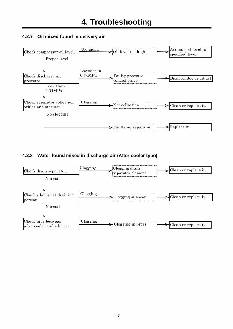
4.2.7 Oil mixed found in delivery air
4.2.8 Water found mixed in discharge air (After cooler type)
Lower than 0.34MPa Check discharge air
pressure. Disassemble or adjust
more than 0.34MPa
Proper level
Too much Arrange oil level to specified lever.
Check separator collection orifice and strainer.
Clogging
Replace it.
No clogging
Clean or replace it.
Faulty pressure control valve
Oil level too high
Not collection
Faulty oil separator
Check compressor oil level.
Check silencer at draining portion
Clean or replace it.
Clean or replace it.
Check pipe between after-cooler and silencer.
Clogging Clean or replace it.
Clogging silencer
Clogging drain separator element
Clogging in pipes
Check drain separator.
Clogging
Clogging
Normal
Normal
4. Troubleshooting
4-8
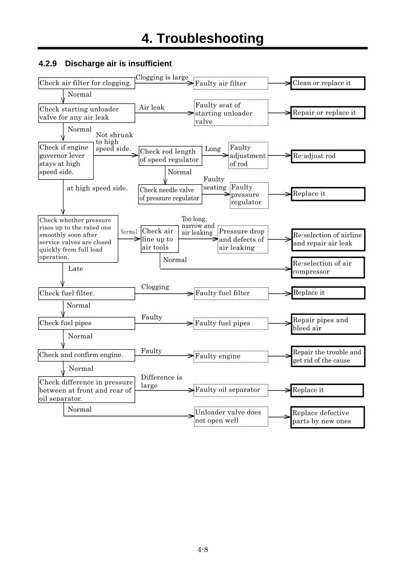
4.2.9 Discharge air is insufficient
Normal Faulty air filter Clean or replace it
Clogging is large
Check starting unloader valve for any air leak Repair or replace it
Air leak
Not shrunk to high speed side.
Re-adjust rod
Replace it
Normal Faulty seating
Long
Normal
Check fuel filter.
Check fuel pipes
at high speed side.
Replace it Clogging
Normal Faulty
Faulty adjustment of rod
Faulty pressure regulator
Check needle valve of pressure regulator
Check rod length of speed regulator
Check air filter for clogging.
Faulty seat of starting unloader valve
Faulty fuel filter
Normal
Faulty fuel pipes Repair pipes and bleed air
Repair the trouble and get rid of the cause
Normal
Check and confirm engine. Faulty engineFaulty
Too long, narrow and air leaking Re-selection of airline
and repair air leak Normal
Re-selection of air compressor
Normal
Check whether pressure rises up to the rated one smoothly soon after service valves are closed quickly from full load operation.
Check air line up to air tools
Pressure drop and defects of air leaking
Late
Replace defective parts by new ones
Unloader valve does not open well
Check difference in pressure between at front and rear of oil separator.
Faulty oil separator Replace it Difference islarge
Normal
Check if engine governor lever stays at high speed side.
4. Troubleshooting
4-9
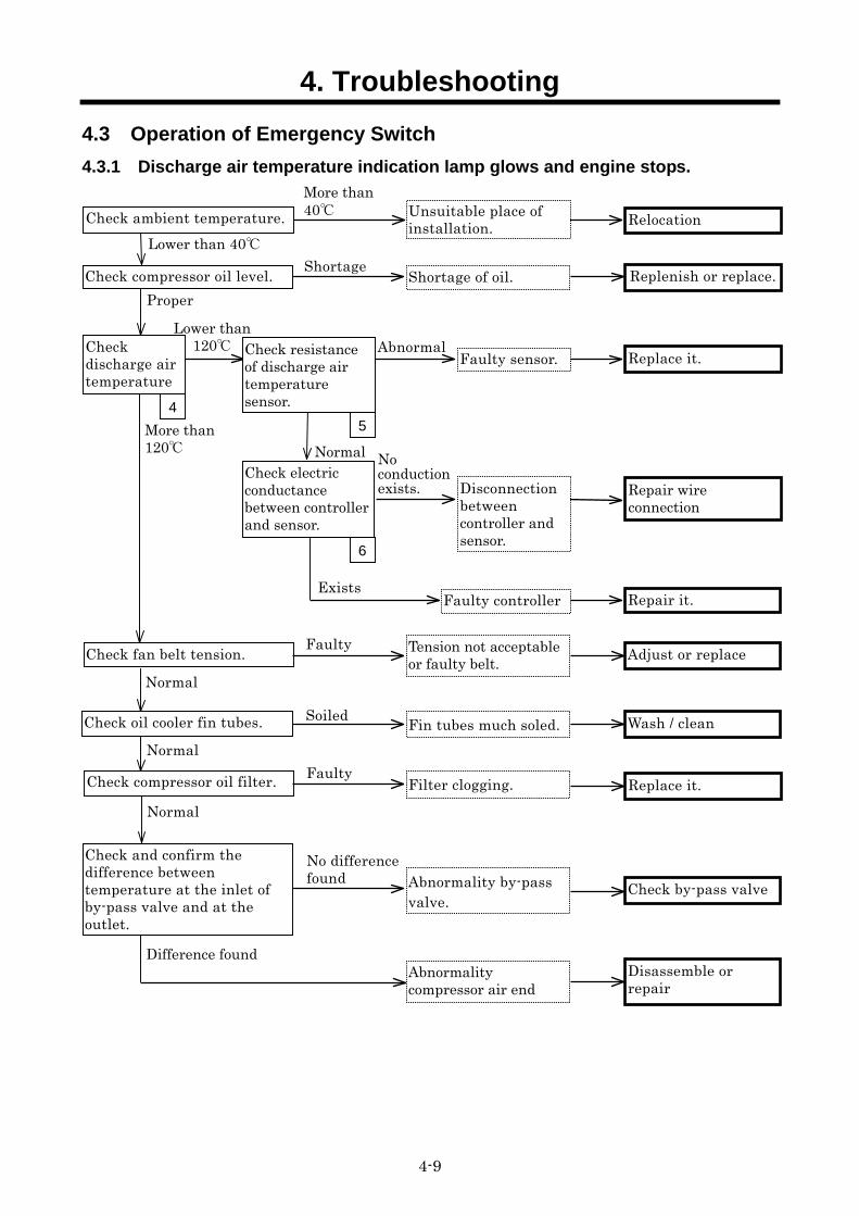
4.3 Operation of Emergency Switch 4.3.1 Discharge air temperature indication lamp glows and engine stops.
Abnormal
More than 40
Faulty controller
Lower than 40
More than 120
Exists
Normal
Check discharge air temperature
4
Check resistance of discharge air temperature sensor.
5
Check electric conductance between controller and sensor.
6
Relocation
Replace it.
Repair wire connection
Repair it.
No conductionexists.
Unsuitable place of installation.
Shortage of oil. Replenish or replace.
Check fan belt tension. Tension not acceptableor faulty belt.
Check compressor oil filter. Filter clogging. Replace it.
Proper
Faulty
Fin tubes much soled.Soiled Wash / cleanNormal
Normal
Normal
Faulty Adjust or replace
Check compressor oil level.
Disconnection between controller and sensor.
Lower than 120
Faulty sensor.
Check oil cooler fin tubes.
Check ambient temperature.
Shortage
Abnormality by-pass valve.
Check by-pass valve
Abnormalitycompressor air end
Disassemble or repair
No difference found
Difference found
Check and confirm the difference between temperature at the inlet of by-pass valve and at the outlet.
4. Troubleshooting
4-10
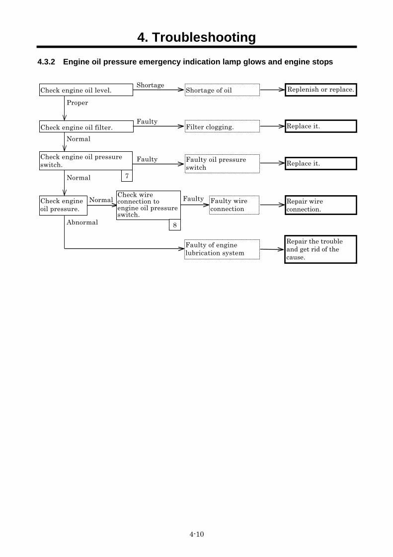
4.3.2 Engine oil pressure emergency indication lamp glows and engine stops
Check engine oil level. Shortage of oil Replenish or replace.Shortage
Check engine oil filter. Filter clogging. Replace it.
Faulty oil pressure switch Replace it.
Normal
Normal
Proper
Faulty
Faulty
Check engine oil pressure.
Faulty of engine lubrication system
Repair the trouble and get rid of the cause.
Normal
Abnormal
Faulty wireconnection
Faulty
Check engine oil pressure switch.
7
Check wire connection to engine oil pressure switch.
8
Repair wire connection.
4. Troubleshooting
4-11
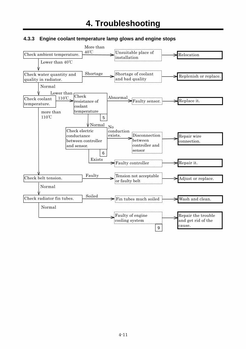
4.3.3 Engine coolant temperature lamp glows and engine stops
Abnormal
Faulty of engine cooling system
Shortage of coolant and bad quality Replenish or replace.Shortage
Check belt tension. Tension not acceptable or faulty belt
Unsuitable place of installation Check ambient temperature.
Fin tubes much soiledSoiled Wash and clean.
Normal
Normal
Normal
Faulty Adjust or replace.
Relocation
Check water quantity and quality in radiator.
More than40
Lower than 40
Check radiator fin tubes.
Faulty sensor.
Faulty controller
more than 110
Exists
Normal
Check resistance of coolant temperature
5
Check electric conductance between controller and sensor.
6
Replace it.
Repair wire connection.
Repair it.
No conductionexists. Disconnection
between controller and sensor
Check coolant temperature.
Repair the trouble and get rid of the cause.
9
Lower than 110
4. Troubleshooting
4-12
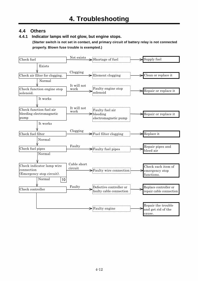
4.4 Others 4.4.1 Indicator lamps will not glow, but engine stops.
(Starter switch is not set in contact, and primary circuit of battery relay is not connected properly. Blown fuse trouble is exempted.)
Check indicator lamp wire connection (Emergency stop circuit).
Normal
Faulty
10
Replace controller or repair cable connection
Check each item of emergency stop functions.
Repair the trouble and get rid of the cause.
Cable short circuit
Check controller
Faulty engine
Faulty wire connection
Defective controller or faulty cable connection
Shortage of fuel Supply fuel Check fuel Not exists
Exists
Check function engine stop solenoid. Repair or replace it
Check fuel filter Fuel filter clogging Replace it Normal
Clogging
Check fuel pipes Faulty fuel pipes Faulty Repair pipes and
bleed air Normal
It works
It will not work
Check function fuel air bleeding electromagnetic pump
Faulty fuel air bleeding electromagnetic pump
Repair or replace it
It works
It will not work
Normal Clean or replace it
Clogging Check air filter for clogging.
Faulty engine stop solenoid
Element clogging
4. Troubleshooting
4-13
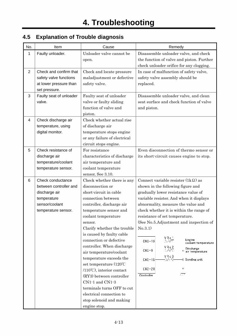
4.5 Explanation of Trouble diagnosis No. Item Cause Remedy
1 Faulty unloader. Unloader valve cannot be open.
Disassemble unloader valve, and check the function of valve and piston. Further check unloader orifice for any clogging.
2 Check and confirm that
safety valve functions
at lower pressure than
set pressure.
Check and locate pressure maladjustment or defective safety valve.
In case of malfunction of safety valve, safety valve assembly should be replaced.
3 Faulty seat of unloader
valve.
Faulty seat of unloader valve or faulty sliding function of valve and piston.
Disassemble unloader valve, and clean seat surface and check function of valve and piston.
4 Check discharge air
temperature, using
digital monitor.
Check whether actual rise of discharge air temperature stops engine or any failure of electrical circuit stops engine.
5 Check resistance of
discharge air
temperature/coolant
temperature sensor.
For resistance characteristics of discharge air temperature and coolant temperature sensor, See 3.10.
Even disconnection of thermo sensor or its short-circuit causes engine to stop.
6 Check conductance
between controller and
discharge air
temperature
sensor/coolant
temperature sensor.
Check whether there is any disconnection or short-circuit in cable connection between controller, discharge air temperature sensor and coolant temperature sensor. Clarify whether the trouble is caused by faulty cable connection or defective controller. When discharge air temperature/coolant temperature exceeds the set temperature (120/110), interior contact (RY3) between controller CN1-1 and CN1-3 terminals turns OFF to cut electrical connection to stop solenoid and making engine stop.
Connect variable resister (1kΩ) as shown in the following figure and gradually lower resistance value of variable resister. And when it displays abnormality, measure the value and check whether it is within the range of resistance of set temperature. (See No.5.Adjustment and inspection of No.3.1)
4. Troubleshooting
4-14
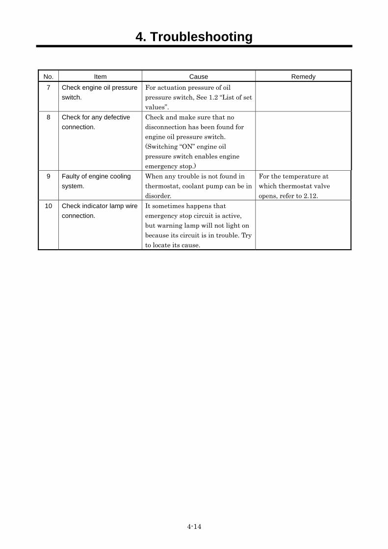
No. Item Cause Remedy
7 Check engine oil pressure
switch.
For actuation pressure of oil pressure switch, See 1.2 “List of set values”.
8 Check for any defective
connection.
Check and make sure that no disconnection has been found for engine oil pressure switch. (Switching “ON” engine oil pressure switch enables engine emergency stop.)
9 Faulty of engine cooling
system.
When any trouble is not found in thermostat, coolant pump can be in disorder.
For the temperature at which thermostat valve opens, refer to 2.12.
10 Check indicator lamp wire
connection.
It sometimes happens that emergency stop circuit is active, but warning lamp will not light on because its circuit is in trouble. Try to locate its cause.
5. References
5-1
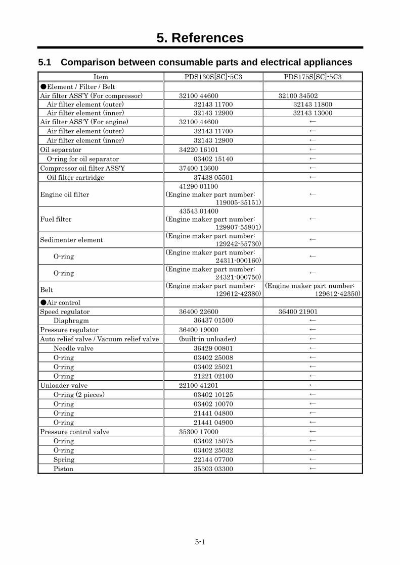
5.1 Comparison between consumable parts and electrical appliances Item PDS130S[SC]-5C3 PDS175S[SC]-5C3
Element / Filter / Belt Air filter ASS’Y (For compressor) 32100 44600 32100 34502
Air filter element (outer) 32143 11700 32143 11800 Air filter element (inner) 32143 12900 32143 13000
Air filter ASS'Y (For engine) 32100 44600 ← Air filter element (outer) 32143 11700 ← Air filter element (inner) 32143 12900 ←
Oil separator 34220 16101 ← O-ring for oil separator 03402 15140 ←
Compressor oil filter ASS'Y 37400 13600 ← Oil filter cartridge 37438 05501 ←
Engine oil filter 41290 01100
(Engine maker part number: 119005-35151)
←
Fuel filter 43543 01400
(Engine maker part number: 129907-55801)
←
Sedimenter element (Engine maker part number: 129242-55730) ←
O-ring (Engine maker part number: 24311-000160) ←
O-ring (Engine maker part number: 24321-000750) ←
Belt (Engine maker part number: 129612-42380)
(Engine maker part number: 129612-42350)
Air control Speed regulator 36400 22600 36400 21901
Diaphragm 36437 01500 ← Pressure regulator 36400 19000 ← Auto relief valve / Vacuum relief valve (built-in unloader) ←
Needle valve 36429 00801 ← O-ring 03402 25008 ← O-ring 03402 25021 ← O-ring 21221 02100 ←
Unloader valve 22100 41201 ← O-ring (2 pieces) 03402 10125 ← O-ring 03402 10070 ← O-ring 21441 04800 ← O-ring 21441 04900 ←
Pressure control valve 35300 17000 ← O-ring 03402 15075 ← O-ring 03402 25032 ← Spring 22144 07700 ← Piston 35303 03300 ←
5. References
5-2
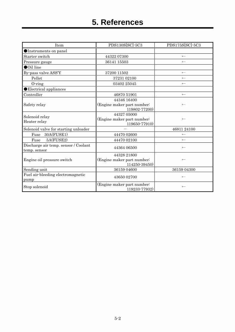
Item PDS130S[SC]-5C3 PDS175S[SC]-5C3
Instruments on panel Starter switch 44322 07300 ← Pressure gauge 36141 15503 ← Oil line By-pass valve ASS'Y 37200 11502 ←
Pellet 37231 02100 ← O-ring 03402 25045 ←
Electrical appliances Controller 46870 51901 ←
Safety relay 44346 16400
(Engine maker part number: 119802-77200)
←
Solenoid relay Heater relay
44327 05000 (Engine maker part number:
119650-77910)←
Solenoid valve for starting unloader - 46811 24100 Fuse 30A(FUSE1) 44470 02600 ← Fuse 5A(FUSE2) 44470 02100 ← Discharge air temp. sensor / Coolant temp. sensor 44364 06500 ←
Engine oil pressure switch 44328 21800
(Engine maker part number: 114250-39450)
←
Sending unit 36159 04600 36159 04300 Fuel air-bleeding electromagnetic pump 43650 02700 ←
Stop solenoid (Engine maker part number: 119233-77932) ←
5-3
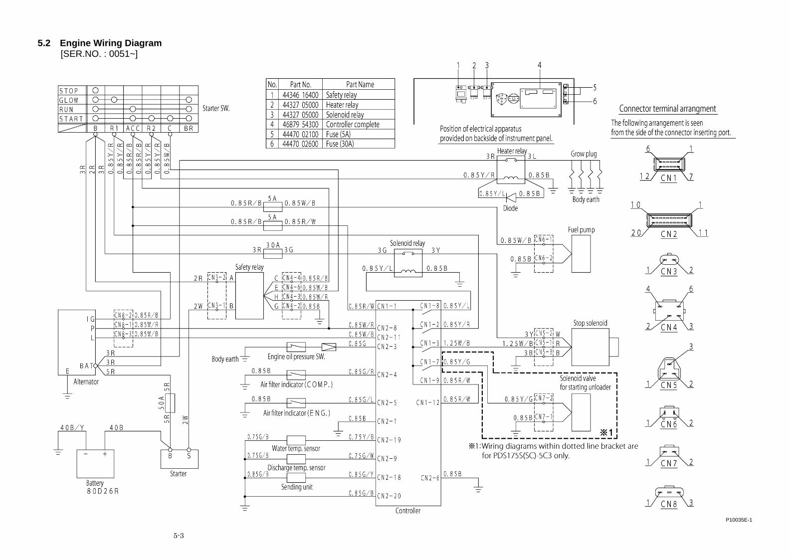
5.2 Engine Wiring Diagram [SER.NO. : 0051~]
P10035E-1
NPC-0071-1PRINTED IN JAPAN 2012. 3
Copyright(C)2012 HOKUETSU INDUSTRIES CO., LTD. All Rights Reserved
HOKUETSU INDUSTRIES CO., LTD.
8TH FLOOR SHINJUKU SAN-EI BLDG, 22-2 NISHI-SHINJUKU 1-CHOME,SHINJUKU-KU TOKYO 160-0023 JAPAN TEL:81-3-3348-7281 FAX:81-3-3348-7289 URL:http//www.airman.co.jp
2006年 2月 27日 初版
2003年 4月 20日 改訂
発行 北 越 工 業 株 式 会 社
新潟県燕市下粟生津3074
TEL 0256-93-5571
FAX 0256-94-7567
(無断複写・転載を禁ず)
本社工場
This text book contains the most recent information available at the time ofprinting, and the contents of the list are based on information in effect at thattime and are subject to change without notice.