fabry–perot interferometers built by photonic crystal fiber pressurization during fusion splicing
TRANSCRIPT

Fabry–Perot interferometers built by photonic crystalfiber pressurization during fusion splicing
Fernando. C. Favero,1,2 Geraud Bouwmans,3 Vittoria Finazzi,2 Joel Villatoro,2,* and Valerio Pruneri3,41Pontifical Catholic University of Rio de Janeiro, Rua Marquês de São Vicente 225, 22453-900, Rio de Janeiro, RJ, Brazil
2ICFO—Institut de Ciencies Fotoniques, Mediterranean Technology Park, 08860, Castelldefels, Barcelona, Spain3PhLAM/IRCICA—Laboratoire de Physique des Lasers Atomes et Molécules/Institut de Recherche sur les Composants logiciels et matériels
pour l’Information et la Communication Avancée, Université Lille, CNRS UMR8523/USR3380, 59658 Villeneuve d’Ascq, France4Also with ICREA-Institució Catalana de Recerca i Estudis Avançats, 08010, Barcelona, Spain
*Corresponding author: [email protected]
Received July 11, 2011; revised September 12, 2011; accepted September 28, 2011;posted September 28, 2011 (Doc. ID 150826); published October 21, 2011
We report on a microscopic Fabry–Perot interferometer whose cavity is a bubble trapped inside an optical fiber. Themicrocavity is formed by pressuring a photonic crystal fiber (PCF) with large voids during fusion splicing with aconventional single-mode fiber. The technique allows achieving high repeatability and full control over the cavitysize and shape. It was found that the size of the PCF voids contributes to control the cavity size independently of thepressure in the PCF. Our devices exhibit a record fringe contrast of 30dB (visibility of 0.999) due to the ellipsoidalcavity whose surfaces compensate for the diffraction of the reflected beam. The strain sensitivity of the interferom-eters is higher when the cavities are ellipsoidal than when they are spherical. © 2011 Optical Society of AmericaOCIS codes: 120.2230, 060.5295, 060.2370, 120.3180.
One of the simplest configurations of a Fabry–Perot in-terferometer (FPI) consists of two uncoated fiber endsseparated by an air gap [1,2]. In such a configuration,the permanent alignment of the fibers imposes con-straints, thus considerable research efforts have beenplaced on making the microcavity inside the fiber. Forexample, the cavity can be carved by means of chemicaletching [3–5] or femtosecond laser micromachining [6,7].Another alternative consists of splicing a short section ofcapillary tube or holey fiber between two single-modefibers [8–11]. Some associated drawbacks of these ap-proaches include costly equipment, multiple fabricationsteps, reflecting surfaces with imperfections due to theremoval of material, and/or low mechanical strength.By splicing a photonic crystal fiber (PCF) or a capillarytube and a conventional optical fiber using the standardarc-discharge technique, it is also possible to form a mi-croscopic air cavity inside the waveguide [12–14]. Themain disadvantage in this case is the low reproducibilityand minimal control over the cavity length.In this Letter we demonstrate high-quality microscopic
FPIs. Their fabrication is carried out by pressurizing in acontrolled manner a PCF during splicing with a standardoptical fiber (SMF-28). The technique allows high repro-ducibility and control over the size and shape of the cav-ities. The micro-FPIs are entirely embedded in the fiberand exhibit record fringe contrast (30 dB) due to theellipsoidal shape of the cavity. It was found that thesize of the PCF voids also helps to control the cavitylength of the interferometers. When the devices are usedfor strain sensing, substantial sensitivity improve-ments where found when the fabrication was via voidpressurization.Figure 1 shows the fabrication and characterization
setup along with the cross section of two PCFs usedin the experiments. The two PCFs had the same hole pat-tern and core/cladding diameter but different hole sizes.The average void diameter of PCF-A and PCF-B were, re-spectively, 4.8 and 5:6 μm. To fabricate the FPIs, the PCF
and the standard fiber were spliced with a conventionalfusion splicing machine (in our case with an EricssonFSU 955). To have control over the cavity length, thevoids of the PCF were pressurized with pure nitrogenusing a homemade device.
It is known that, when an SMF and a PCF are fusionspliced, the PCF’s air holes may entirely collapse [13]. Asa result, part of the air (or nitrogen) originally inside thevoids can be trapped, thus forming a microscopic cavity[12,13]. A collection of samples were fabricated at differ-ent pressures with a fusion program that had the follow-ing parameters: prefusion time, 0:3 s; prefusion arc,13mA; overlap, 5 μm; fusion current 1, 12mA. The re-maining parameters were those set in the machine forsplicing SMFs. When the PCFs were not pressurized,the cavities had a spherical shape [12,13], but their sizescould not be controlled. However, when the PCF voidswere pressurized, the cavities had an ellipsoidal shape(see Fig. 2) whose dimensions depended on the pressure.The short overlap and the pressure in the PCF contribu-ted to achieve elliptical cavities. In all cases, the micro-bubbles were formed at the interface with the SMF, in
Fig. 1. (Color online) Drawing of the fabrication and charac-terization setup. LED stands for light emitting device, FOC forfiber optic circulator, and OSA for optical spectrum analyzer.The cross sections of the PCFs used are shown.
November 1, 2011 / Vol. 36, No. 21 / OPTICS LETTERS 4191
0146-9592/11/214191-03$15.00/0 © 2011 Optical Society of America
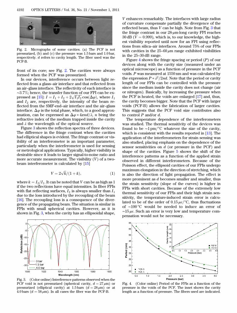
front of its core; see Fig. 2. The cavities were alwaysformed when the PCF was pressurized.In our devices, interference occurs between light re-
flected from a glass–air interface and that reflected froman air–glass interface. The reflectivity of each interface is∼3:7%; hence, the transfer function of our FPI can be ex-pressed as [15]: I ¼ I1 þ I2 þ 2
ffiffiffiffiffiffiffiffiffi
I1I2p
cosðΔφÞ, where I1and I2 are, respectively, the intensity of the beam re-flected from the SMF-end–air interface and the air–glassinterface. Δφ is the total phase, which, to a good approx-imation, can be expressed as Δφ ≈ 4πnd=λ, n being therefractive index of the medium trapped inside the cavityand λ the wavelength of the optical source.Figure 3 shows the reflection spectra of three devices.
The difference in the fringe contrast when the cavitieshad elliptical shapes is evident. The fringe contrast or vis-ibility of an interferometer is an important parameter,particularly when the interferometer is used for sensingor metrological applications. Typically, higher visibility isdesirable since it leads to larger signal-to-noise ratio andmore accurate measurement. The visibility (V) of a two-beam interferometer is calculated by [15]
V ¼ 2ffiffiffi
kp
=ð1þ kÞ; ð1Þ
where k ¼ I2=I1. It can be noted that V can be as high as 1if the two reflections have equal intensities. In fiber FPIswith flat reflecting surfaces, I2 is always smaller than I1due to the loss introduced by the recoupling of the beam[16]. The recoupling loss is a consequence of the diver-gence of the propagating beam. The situation is similar inFPIs with small spherical cavities. However, as it isshown in Fig. 3, when the cavity has an ellipsoidal shape,
V enhances remarkably. The interfaces with large radiusof curvature compensate partially the divergence of thereflected beam, thus V can be high. Note from Fig. 3 thatthe fringe contrast in our 28-μm-long cavity FPI reaches30 dB (V ¼ 0:999), which is, to our knowledge, the high-est visibility reported until now for an FPI using reflec-tions from silica–air interfaces. Around 75% of our FPIswith cavities in the 25–60 μm range exhibited visibilitiesin the 25–30dB range.
Figure 4 shows the fringe spacing or period (P) of ourdevices along with the cavity size (measured under anoptical microscope) as a function of pressure in the PCFvoids. P was measured at 1550 nm and was calculated bythe expression P ≈ λ2=2nd. Note that the period or cavitylength of our FPIs can be controlled with the pressuresince the medium inside the cavity does not change (airor nitrogen). Basically, by increasing the pressure whenthe PCF is heated, the voids are enlarged [17] and, thus,the cavity becomes bigger. Note that the PCF with largervoids (PCF-B) allows the fabrication of larger cavities.This suggests that the PCF void size contributes alsoto control P and/or d.
The temperature dependence of the interferometerswas studied. The thermal sensitivity of the devices wasfound to be ∼1 pm=°C whatever the size of the cavity,which is consistent with the results reported in [13]. Theapplication of the interferometers for strain sensing wasalso studied, placing emphasis on the dependence of thesensor sensitivities on d (or pressure in the PCF) andshape of the cavities. Figure 5 shows the shift of theinterference patterns as a function of the applied strainobserved in different interferometers. Because of thePoisson effect, the ellipsoid cavities of our FPIs undergomaximum elongation in the direction of stretching, whichis also the direction of light propagation. The effect ismore prominent as d becomes smaller and smaller, thusthe strain sensitivity (slope of the curves) is higher inFPIs with short cavities. Because of the extremely lowthermal sensitivity of our FPIs and their high strain sen-sitivity, the temperature-induced strain error is calcu-lated to be of the order of 0:15 με=°C, thus fluctuationsof ∼100 °C would be needed to induce an error of∼15 με. Such an error is very low and temperature com-pensation would not be necessary.
Fig. 2. Micrographs of some cavities. (a) The PCF is notpressurized, (b) and (c) the pressure was 1:5 bars and 1:0 bar,respectively. d refers to cavity length. The fiber used was thePCF-B.
Fig. 3. (Color online) Interference patterns observed when thePCF void is not pressurized (spherical cavity, d ¼ 27 μm) orpressurized (elliptical cavity) at 1:5 bars (d ¼ 28 μm) or at4:0 bars (d ¼ 58 μm). In all cases the fiber was the PCF-B.
Fig. 4. (Color online) Period of the FPIs as a function of thepressure in the voids of the PCF. The inset shows the cavitylength as a function of pressure. The fibers used are indicated.
4192 OPTICS LETTERS / Vol. 36, No. 21 / November 1, 2011

In conclusion, we have reported on the fabrication ofmicroscopic FPIs in which the cavity is an air bubbletrapped inside an optical fiber. Such a cavity is formedby fusion splicing together a standard SMF and a PCF.The voids of the PCF are pressurized in a controlledmanner to achieve high reproducibility and control overthe cavity length. It was found that the size of the PCFvoids help to control the cavity dimensions. Our FPIs ex-hibited visibilities as high as 0.999 due to their ellipsoidalshape, which arises due to pressurization of the PCF andthe splicing conditions. The sensing capabilities of the de-vices were investigated. High strain sensitivities and lowtemperature sensitivities were observed, thus suggestingthat temperature compensation may not be required.
This work was partially supported by the SpanishMinisterio de Ciencia e Innovación (MCI) under projectTEC2010-14832 and the “Ramón y Cajal” program, theCoordenaçao de Aperfeiçoam-ento Pessoal de NívelSuperior (251710-8 Ph.D. Fellowship), the Fonds
Europeen de Developpement Economique des Regional(FEDER) through the Contrat de Projets Etat Region(CPER) 2007-2013, and by the Fundació Privada CellexBarcelona.
References
1. Y. J. Rao, Opt. Fiber Technol. 12, 227 (2006).2. J. Wang, B. Dong, E. Lally, J. Gong, M. Han, and A. Wang,
Opt. Lett. 35, 619 (2010).3. X. Chen, F. Shen, Z. Wang, Z. Huang, and A. Wang, Appl.
Opt. 45, 7760 (2006).4. V. R. Machavaram, R. A. Badcock, and G. F. Fernando,
Sens. Actuators A 138, 248 (2007).5. E. Cibula and D. Donlagic, Opt. Express 15, 8719 (2007).6. Z. L. Ran, Y. J. Rao, H. Y. Deng, and X. Liao, Opt. Lett. 32,
3071 (2007).7. T. Wei, Y. Han, H.-L. Tsai, and H. Xiao, Opt. Lett. 33,
536 (2008).8. J. S. Sirkis, D. D. Brennan, M. A. Putman, T. A. Berkoff,
A. D. Kersey, and E. J. Friebele, Opt. Lett. 18, 1973 (1993).9. Q. Shi, F. Lv, Z. Wang, L. Jin, J. J. Hu, Z. Liu, G. Kai, and
X. Dong, IEEE Photon. Technol. Lett. 20, 237 (2008).10. O. Frazao, S. H. Aref, J. M. Baptista, J. L. Santos, H. Latifi,
F. Farahi, J. Kobelke, and K. Schuster, IEEE Photon.Technol. Lett. 21, 1229 (2009).
11. C. Wu, H. Y. Fu, K. K. Qureshi, B.-O. Guan, and H. Y. Tam,Opt. Lett. 36, 412 (2011).
12. E. Li, G. D. Peng, and X. Ding, Appl. Phys. Lett. 92,101117 (2008).
13. J. Villatoro, V. Finazzi, G. Coviello, and V. Pruneri, Opt. Lett.34, 2441 (2009).
14. J. Ma, J. Ju, L. Jin, W. Jin, and D. Wang, Opt. Express 19,12418 (2011).
15. Y. Zhang, Y. Li, T. Wei, X. Lan, Y. Huang, G. Chen, andH. Xiao, IEEE Photon. J. 2, 469 (2010).
16. A. S. Gerges, T. P. Newson, F. Farahi, J. D. C. Jones, andD. A. Jackson, Opt. Commun. 68, 157 (1988).
17. W. Wadsworth, A. Witkowska, S. Leon-Saval, and T. Birks,Opt. Express 13, 6541 (2005).
Fig. 5. (Color online) Shifts of the interference patterns as afunction of strain in FPIs with ellipsoidal cavities of differentsizes. For comparison, the response of a FPI with a sphericalcavity is shown.
November 1, 2011 / Vol. 36, No. 21 / OPTICS LETTERS 4193