f e a t u r i n g - amazon web...
TRANSCRIPT

©American Audio® - www.americanaudio.eu Versadeck™ User Manual Page 1
F E A T U R I N G
©American Audio® - www.americanaudio.eu Versadeck™ User Manual Page 2

©American Audio® - www.americanaudio.eu Versadeck™ User Manual Page 3
Please Note: All specifications and improvements to and in the design of this unit and this
manual are subject to change at any time without any prior written or published noticed.

©American Audio® - www.americanaudio.eu Versadeck™ User Manual Page 4
6122 S. Eastern Ave
Los Angeles Ca. 90040
www.americanaudio.eu
©American Audio® - www.americanaudio.eu Versadeck™ User Manual Page 5
1. TABLE OF CONTENTS
1. Table of Contents ................................................................................................................ 5
2. Electrical Safety Precautions ............................................................................................... 8
3. Important Safety Precautions ........................................................................................... 10
4. Further Safety Instructions ............................................................................................... 13
5. Unpacking.......................................................................................................................... 15
6. Introduction ...................................................................................................................... 16
6.1 Customer Support .......................................................................................................... 16
7. Set-Up Precautions ........................................................................................................... 17
7.1 Operating Determinations ............................................................................................. 17
8. Main Features ................................................................................................................... 18
9. Set-Up................................................................................................................................ 20
9.1 USB Information ............................................................................................................. 20
9.2 Checking the Contents ................................................................................................... 20
9.2 Installing the Units .......................................................................................................... 20
10. General Functions and Controls .................................................................................... 22
10.1 Top Unit Player Controls .............................................................................................. 22
10.2 Top Unit Mixer Controls ............................................................................................... 27
10.3 Front Panel ................................................................................................................... 30
10.4 Rear Panel ..................................................................................................................... 31
10.5 VFD Display ................................................................................................................... 33
11. Internal Menu ................................................................................................................ 35
12. Basic Operations ............................................................................................................ 37
12.1 Loading/Ejecting an USB Device ................................................................................... 37
12.2 Selecting Tracks ............................................................................................................ 37
12.3 Starting Playback .......................................................................................................... 38
©American Audio® - www.americanaudio.eu Versadeck™ User Manual Page 6
12.4 Pausing ......................................................................................................................... 38
12.5 Auto CUE....................................................................................................................... 38
12.6 Stopping Playback ........................................................................................................ 38
12.7 Frame Search ................................................................................................................ 39
12.8 Setting a Cue Point ....................................................................................................... 39
12.9 Creating and Playing a seamless Loop ......................................................................... 40
12.10 Changing the Time Display (66) / Time Bar (67) ........................................................ 43
12.11 Bank Buttons (19) ....................................................................................................... 43
13. Pitch Adjustments ......................................................................................................... 45
13.1 Pitch Slider (10) ............................................................................................................ 45
13.2 Pitch Bending ................................................................................................................ 46
13.3 Jog Wheel (16) .............................................................................................................. 48
14. Jog Wheel Functions...................................................................................................... 49
14.1 Jog Wheel Touch Sensitivity ......................................................................................... 49
14.2 A.CUE ............................................................................................................................ 49
14.3 Vinyl Mode and CDJ Mode ........................................................................................... 50
15. Built-In Effects ............................................................................................................... 52
15.1 Skid Effect ..................................................................................................................... 52
15.2 Filter Effect ................................................................................................................... 52
15.3 Echo Effect .................................................................................................................... 53
15.4 Flanger Effect ................................................................................................................ 53
15.5 Parameters ................................................................................................................... 54
15.6 Hold Button .................................................................................................................. 54
16. Playlist Operation .......................................................................................................... 55
17. Relay Mode (Flip-Flop™) ............................................................................................... 56
17.1 Relay single tracks ........................................................................................................ 56
17.2 Flip-Flop™ entire Folders .............................................................................................. 56
©American Audio® - www.americanaudio.eu Versadeck™ User Manual Page 7
18. Database Builder ........................................................................................................... 57
18.1 Minimum Hardware Requirements ............................................................................. 57
18.2 Installation .................................................................................................................... 57
18.3 Scan and Create ............................................................................................................ 58
18.4 Possible Errors .............................................................................................................. 60
19. MIDI Map ....................................................................................................................... 61
19.1 MIDI Table .................................................................................................................... 61
19.2 MIDI Types .................................................................................................................... 64
20. Mixer Setup ................................................................................................................... 66
20.1 Connecting to a computer ............................................................................................ 66
20.2 Typical Balanced Output Set-up ................................................................................... 67
21. Crossfader Replacement ............................................................................................... 68
Replacing How-To ................................................................................................................. 68
22. Troubleshooting ............................................................................................................ 69
23. ROHS – A Contribution to the Conservation of Environment ....................................... 70
24. WEEE – Waste of Electrical and Electronic Equipment ................................................. 71
25. Specifications ................................................................................................................. 72
25.1 General ......................................................................................................................... 72
25.2 USB Player Section ....................................................................................................... 72
25.3 MP3 Format .................................................................................................................. 73
©American Audio® - www.americanaudio.eu Versadeck™ User Manual Page 8
2. ELECTRICAL SAFETY PRECAUTIONS
The lightning flash with an arrow triangular symbol is intended to alert the
user to the presence of non-insulated “dangerous voltage” within the
product’s enclosure, and may be of sufficient magnitude to constitute a
risk of electric shock.
The exclamation point triangular symbol is intended to alert the user to
the presence of important operating and maintenance (servicing)
instructions in the user manual accompanying the unit.
CAUTION
RISK OF ELECTRIC SHOCK! DO NOT OPEN!
TO REDUCE THE RISK OF ELECTRIC SHOCK, DO NOT
REMOVE THE COVER RACK. THERE ARE NO USER
SERVICEABLE PARTS INSIDE. REFER SERVICE TO YOUR
AUTHORIZED AMERICAN AUDIO® SERVICE DEALER.
Please carefully read and understand the instructions in this manual
thoroughly before attempting to operate this unit. These instructions
contain important safety information regarding the use and maintenance
of this unit. Take special care to follow all warning symbols and labels
both on the unit and printed in this manual. Also, Please keep this
manual with the unit, for future reference.
CAUTION:
Handle the power supply cord carefully. Do not damage or deform; it may cause
electric shock or malfunction when used. Hold the plug attachment when removing
from wall outlet. Do not pull on the cord.
To avoid electric shock, do not open the top cover when the unit is plugged in. If
problems occur with the unit, call your local American Audio® dealer.
Do not place metal objects or spill liquid inside the unit. Electric shock or malfunction
may occur.
©American Audio® - www.americanaudio.eu Versadeck™ User Manual Page 9
CAUTION:
TO PREVENT ELECTRIC SHOCK DO NOT USE THIS
(POLARIZED) PLUG WITH AN EXTENSION CORD,
RECEPTACLE OR OTHER OUTLET UNLESS THE BLADES
CAN BE CAREFULLY INSERTED TO PREVENT BLADE
EXPOSURE!
CAUTION:
USE OF CONTROLS OR ADJUSTMENTS OTHER THAN THOSE SPECIFIED HEREIN MAY
RESULT IN HAZARDOUS RADIATION EXPOSURE.
THE DEVICE SHOULD NOT BE ADJUSTED OR REPAIRED BY ANYONE EXCEPT PROPERLY
QUALIFIED SERVICE PERSONNEL.
NOTE:
This unit may cause interference to radio and
television reception.
NOTE:
This device uses a semiconductor laser. It is
recommended for use in a room at the
following temperature: 41˚- 95˚F or 5˚C -
35˚C.
WARNING:
TO PREVENT FIRE OR SHOCK HAZARD, DO NOT
EXPOSE THIS DEVICE TO WATER OR MOISTURE!
©American Audio® - www.americanaudio.eu Versadeck™ User Manual Page 10
3. IMPORTANT SAFETY PRECAUTIONS Read Instructions – All the safety and operating instructions should be read before the
product is operated.
Retain Instructions – The safety and operating instructions should be retained for future
reference.
Heed Warnings – All warnings on the product and in the operating instructions should be
adhered to.
Follow Instructions – All operating and use instructions should be followed.
Cleaning – The product should be cleaned only with a polishing cloth or a soft dry cloth.
Never clean with furniture wax, benzine, insecticides or other volatile liquids since they may
corrode the cabinet.
Attachments – Do not use attachments not recommended by the product manufacturer as
they may cause hazards.
Water and Moisture – Do not use this product near water — for example, near a bathtub,
wash bowl, kitchen sink, or laundry tub, in a wet basement or near a swimming pool and the
like.
Accessories – Do not place this product on an unstable cart, stand, tripod, bracket, or table.
The product may fall, causing serious injury to a child or adult and serious damage to the
product. Use only with a cart, stand, tripod, bracket, or table recommended by the
manufacturer, or sold with the product. Any mounting of the product should follow the
manufacturer’s instructions, and should use a mounting accessory recommended by the
manufacturer.
Ventilation – Slots and openings in the cabinet are provided for ventilation and to ensure
reliable operation of the product and to protect it from overheating, and these openings
must not be blocked or covered. The openings should never be blocked by placing the
product on a bed, sofa, rug, or other similar surface. This product should not be placed in a
built-in installation such as a bookcase or rack unless proper ventilation is provided or the
manufacturer’s instructions have been adhered to.
Power Sources – This product should be operated only from the type of power source
indicated on the marking label. If you are not sure of the type of power supply to your home,
consult your product dealer or local power company.
Cart – A product and cart combination should be moved with care. Quick
stops, excessive force, and uneven surfaces may cause the product and cart
combination to overturn.
©American Audio® - www.americanaudio.eu Versadeck™ User Manual Page 11
Location – The appliance should be installed in a stable location.
Nonuse Periods – The power cord of the appliance should be unplugged from the outlet
when left unused for a long period of time.
Grounding or Polarization
If this product is equipped with a polarized alternating current line plug (a plug
having one blade wider than the other), it will fit into the outlet only one way. This is
a safety feature. If you are unable to insert the plug fully into the outlet, try reversing
the plug. If the plug should still fail to fit, contact your electrician to replace your
obsolete outlet. Do not defeat the safety purpose of the polarized plug.
If this product is equipped with a three-wire grounding type plug, a plug having a
third (grounding) pin, it will only fit into a grounding type power outlet. This is a
safety feature. If you are unable to insert the plug into the outlet, contact your
electrician to replace your obsolete outlet. Do not defeat the safety purpose of the
grounding type plug.
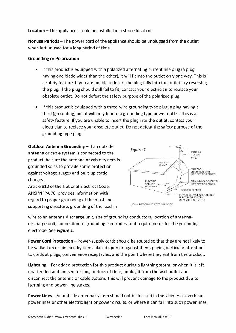
wire to an antenna discharge unit, size of grounding conductors, location of antenna-
discharge unit, connection to grounding electrodes, and requirements for the grounding
electrode. See Figure 1.
Power Cord Protection – Power-supply cords should be routed so that they are not likely to
be walked on or pinched by items placed upon or against them, paying particular attention
to cords at plugs, convenience receptacles, and the point where they exit from the product.
Lightning – For added protection for this product during a lightning storm, or when it is left
unattended and unused for long periods of time, unplug it from the wall outlet and
disconnect the antenna or cable system. This will prevent damage to the product due to
lightning and power-line surges.
Power Lines – An outside antenna system should not be located in the vicinity of overhead
power lines or other electric light or power circuits, or where it can fall into such power lines
Outdoor Antenna Grounding – If an outside
antenna or cable system is connected to the
product, be sure the antenna or cable system is
grounded so as to provide some protection
against voltage surges and built-up static
charges.
Article 810 of the National Electrical Code,
ANSI/NFPA 70, provides information with
regard to proper grounding of the mast and
supporting structure, grounding of the lead-in
©American Audio® - www.americanaudio.eu Versadeck™ User Manual Page 12
or circuits. When installing an outside antenna system, extreme care should be taken to
keep from touching such power lines or circuits as contact with them might be fatal.
Overloading – Do not overload wall outlets, extension cords, or integral convenience
receptacles as this can result in a risk of fire or electric shock.
Object and Liquid Entry – Never push objects of any kind into this product through openings
as they may touch dangerous voltage points or short-out parts that could result in a fire or
electric shock. Never spill liquid of any kind on the product.
Servicing – Do not attempt to service this product yourself as opening or removing covers
may expose you to dangerous voltage or other hazards. Refer all servicing to qualified
service personnel.
Damage Requiring Service – Unplug this product from the wall outlet and refer servicing to
qualified service personnel under the following conditions:
When the power supply cord or plug is damaged.
If liquid has been spilled, or objects have fallen into the product.
If the product has been exposed to rain or water.
If the product does not operate normally by following the operating instructions.
Adjust only those controls that are covered by the operating instructions as an
improper adjustment of other controls may result in damage and will often require
extensive work by a qualified technician to restore the product to its normal
operation.
If the product has been dropped or damaged in any way.
When the product exhibits a distinct change in performance - this indicates a need
for service.
Replacement Parts – When replacement parts are required, be sure the service technician
has used replacement parts specified by the manufacturer or have the same characteristics
as the original part. Unauthorized substitutions may result in fire, electric shock, or other
hazards.
Safety Check – Upon completion of any service or repairs to this product, ask the service
technician to perform safety checks to determine that the product is in proper operating
condition.
Wall or Ceiling Mounting – The product should not be mounted to a wall or ceiling.
Heat – The product should be situated away from heat sources such as radiators, heat
registers, stoves, or other products (including amplifiers) that produce heat.
©American Audio® - www.americanaudio.eu Versadeck™ User Manual Page 13
4. FURTHER SAFETY INSTRUCTIONS Read Instructions – All the safety and operating instructions should be read before the unit
is operated. The safety and operating instructions should be saved for future reference.
Heed Warnings – All warnings on the unit and in the operating instructions should be
adhered to.
Water and Moisture – The device should not be used near water - for example, near a bath
tub, kitchen sink, laundry tub, in a wet basement or near a swimming pool, etc.
Ventilation – The device should be situated so that its location or position does not interfere
with its proper ventilation. For example, the device should not be situated on a bed, sofa,
rug, or similar surface that may block the ventilation openings; or, placed in a built-in
installation, such as a bookcase or cabinet that may impede the flow of air through the
ventilation openings.
Heat – The device should be situated away from heat sources such as radiators, heat
registers, stoves, or other appliances (including amplifiers) that produce heat.
Power Sources – The device should be connected to a power supply only of the type
described in the operating instructions or as marked on the unit.
Servicing – The user should not attempt to service the device beyond that described in the
operating instructions. All other servicing should be referred to qualified service personnel.
The device should be serviced by qualified service personnel when:
The power-supply cord or the plug has been damaged.
Objects have fallen, or liquid has been spilled into the unit.
The unit has been exposed to rain or water.
The unit does not appear to operate normally or exhibits a marked change in
performance.
©American Audio® - www.americanaudio.eu Versadeck™ User Manual Page 14
The serial and model number for this unit is located on the rear panel. Please write down the
numbers here and retain for future reference.
Model No. ____________________________________________________________
Serial No. ____________________________________________________________
Purchase Notes ____________________________________________________________
Date of Purchase ____________________________________________________________
Dealer Name ____________________________________________________________
Dealer Address _____________________________________________________________
___________________________________________________________________________
___________________________________________________________________________
Dealer Phone ______________________________________________________________
©American Audio® - www.americanaudio.eu Versadeck™ User Manual Page 15
5. UNPACKING Every Versadeck™ has been thoroughly tested and has been shipped in perfect operating
condition.
Carefully check the shipping carton for damage that may have occurred during shipping. If
the carton appears to be damaged, carefully inspect your system for any damage and be
sure all equipment necessary to operate the system has arrived intact.
In the event damage has been found or parts are missing, please contact our toll free
customer support number for further instructions.
Please do not return the system to your dealer without first contacting customer support.
©American Audio® - www.americanaudio.eu Versadeck™ User Manual Page 16
6. INTRODUCTION Congratulations and thank you for purchasing the American Audio® Versadeck™. This device
is a representation of American Audio’s® continuing commitment to produce the best and
highest quality audio products possible at an affordable price.
Please read and understand this manual completely before attempting to operate your new
device. This booklet contains important information concerning the proper and safe
operation of your new device.
6.1 CUSTOMER SUPPORT American Audio® provides a toll free customer support line to provide set up help and to
answer any questions, should you encounter problems during your initial set-up or
operation. You may also visit us on the web at www.AmericanAudio.us for any comments or
suggestions.
Service Hours are Monday through Friday 08:30 to 17:00 GMT+1.
Voice: 0031 45 546 85 30
Fax: 0031 45 546 85 99
E-mail: [email protected]
For spare parts please look in our online part shop.
Caution!
There are no user serviceable parts inside this device. Do not attempt any repairs by yourself.
Doing so will void your manufactures warranty. In the unlikely event your device may require
service, please contact American Audio® customer support.
Do not discard the packing carton in the trash. Please recycle whenever possible.
©American Audio® - www.americanaudio.eu Versadeck™ User Manual Page 17
7. SET-UP PRECAUTIONS Please be sure to make any connections before plugging the device in to an electrical outlet.
All fader and volume controls should be set to zero or minimum position, before the device
is switched on.
If the device has been exposed to drastic temperature fluctuation (e.g. after transportation),
do not switch on the device immediately. The arising condensation of water might damage
your device. Leave the device switched off until it has reached room temperature.
7.1 OPERATING DETERMINATIONS When installing this device, please make sure that it is not exposed to extreme heat,
moisture or dust!
Do not operate the mixer in extremely hot (more than 30°C / 86°F) or extremely cold
(less than 5°C / 40°F) surroundings.
Keep the unit out of direct sunlight and away from heaters.
Operate the device only after becoming familiar with its functions. Do not permit
operation by persons not qualified for operating the unit. Most damages are the result
of unprofessional operation!
©American Audio® - www.americanaudio.eu Versadeck™ User Manual Page 18
8. MAIN FEATURES ID3 Track Recognition Real Time Scratch Play
Auto Cue Skid Effect
1/75th second frame search Filter Effect
Real time cue (“Cue on the Fly”) Echo Effect
Fader “Q” Start Control (a) Flanger Effect
Pitch Display System Lock
RCA Stereo Outputs Music Master Tempo
Large bright VFD display can be viewed
from wide angles
8 different speed scans (4 Forward/4
Reverse)
Folder Search for MP3's Cue Mixing
Seamless Loop (uninterrupted loop
playback)
3 Band EQ per channel
Sampler (Forward & Reverse Sampling) Front & Rear Access Mic Jack
10 Second Digital Anti-Shock Master & Booth Outputs
Flip-Flop (Relay Playback) (b) 2 Phono & 2 Line Level Inputs
Jog Wheel Pitch Bend +/-100% Balanced XLR Outputs
Jog Wheel Sensitivity Adjustment Headphone Jack w/ Volume Control
Selectable Single or Continuous Play 4 Programmable Cue (Bank) Buttons
Plays Mp3/WAV* files from either USB
Stick or SD/SDHC Card via USB Card
Reader
Instant Start within 10ms (sound is
produced immediately when the Play
button is pressed)
* WAV Files: 1411Kbps PCM Adjustable Pitch Percentages: +/-6%,
+/-10%, or +/-16%
(a) FADER “Q” START CONTROL: Set up your Versadeck™ as described in chapter 9 (Set-Up)
and 20 (Mixer Setup) of this manual. After set up is completed load your players. By moving
the mixer’s crossfader from left to right you can start and pause each player’s playback
functions. For Example, when using the Versadeck™ player, if your mixer’s crossfader is all
the way to the left (Player 1 is playing, Player 2 is in cue or pause mode), and you move the
fader at least 20% to the right, Player t2will begin to play. When the crossfader is to the
©American Audio® - www.americanaudio.eu Versadeck™ User Manual Page 19
right, and you move it 20% to the left, Player 1 will begin to play. You can create great
effects similar to scratching with this feature. After storing cue points on each side of the
player, different songs may quickly be recalled by moving the mixer crossfader back and
forth. New cue points can be easily selected on the Versadeck™ player, please see chapter
12.8 Setting a Cue Point. “Q” Start control is easy to use and mastering this feature will help
you create amazing effects with your music.
(b) RELAY (FLIP-FLOP™): Set up your Versadeck™ as described in chapter 9 (Set-Up) and 20
(Mixer Setup) of this manual. This feature will start the next player once one player has
ended. For example, if Player 1 is playing a track and it ends, Player 2 will instantly begin to
play. You may set RELAY to play track to track or folder to folder. For more information on
this feature please read chapter 17 (Relay Mode (Flip-Flop™)).
©American Audio® - www.americanaudio.eu Versadeck™ User Manual Page 20
9. SET-UP
9.1 USB INFORMATION The Versadeck™ will only read MP3 files or WAV files.
If you are using a SD Card via USB SD Card reader, you must remove the USB SD Card
reader first to change SD Card's. Please do not remove the SD Card from the USB SD
Card reader while the USB card reader is still connected to the unit.
Only supports FAT/FAT32 formatted devices.
NOTE: For higher quality MP3 files (more than 128 kbps) American Audio® recommends
"High Speed" SD Cards. Using high speed cards will ensure the best performance with your
American Audio® Player.
NOTE: If the Versadeck™ cannot read your USB device, please make sure that it FAT
formatted.
9.2 CHECKING THE CONTENTS Be sure your Versadeck™ was shipped with the following:
Versadeck™ Professional Media Player/Mixer
Software CD
Warranty Card
Power Cord
9.2 INSTALLING THE UNITS CAUTION: To avoid severe damage to the unit, be sure the power is off when making
connections to the unit.
SYSTEM POWER-UP SEQUENCE
Turn ON the Versadeck™.
Next, turn ON your speakers.
©American Audio® - www.americanaudio.eu Versadeck™ User Manual Page 21
SYSTEM POWER-UP SEQUENCE WITH CONNECTED MIXER, AMP, ACTIVE SPEAKERS, OR EXTERNAL
DEVICE
Turn ON the amp, mixer, speakers, or any external device first.
Next, turn ON the Versadeck™.
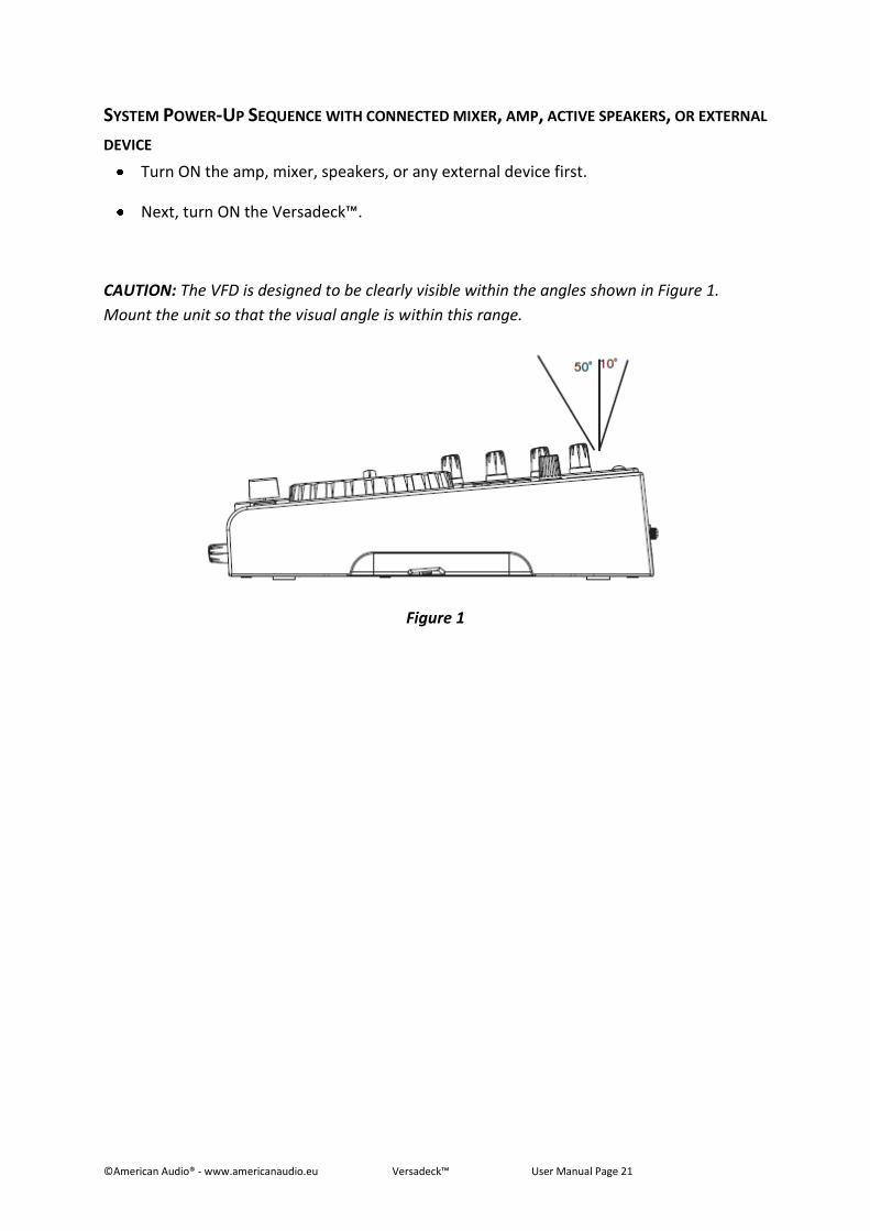
CAUTION: The VFD is designed to be clearly visible within the angles shown in Figure 1.
Mount the unit so that the visual angle is within this range.
Figure 1
©American Audio® - www.americanaudio.eu Versadeck™ User Manual Page 22
10. GENERAL FUNCTIONS AND CONTROLS
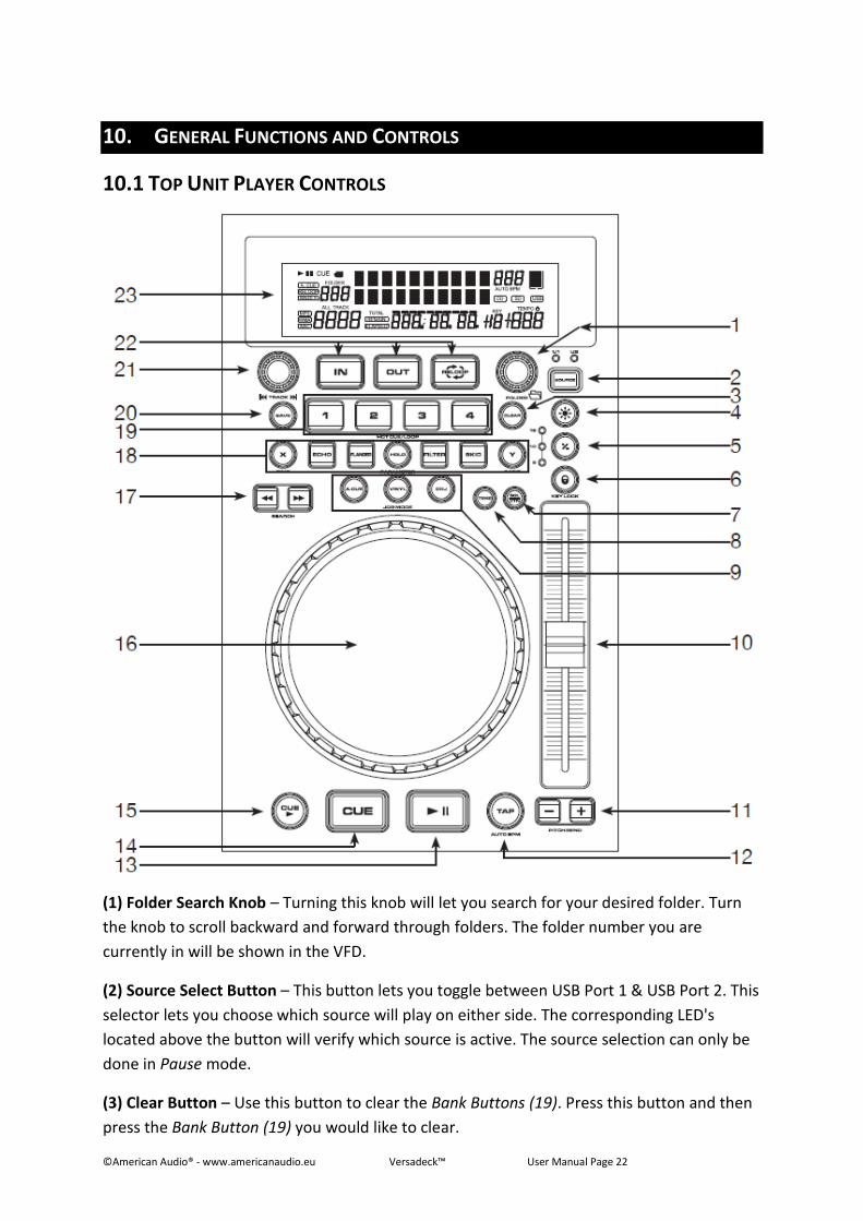
10.1 TOP UNIT PLAYER CONTROLS
(1) Folder Search Knob – Turning this knob will let you search for your desired folder. Turn
the knob to scroll backward and forward through folders. The folder number you are
currently in will be shown in the VFD.
(2) Source Select Button – This button lets you toggle between USB Port 1 & USB Port 2. This
selector lets you choose which source will play on either side. The corresponding LED's
located above the button will verify which source is active. The source selection can only be
done in Pause mode.
(3) Clear Button – Use this button to clear the Bank Buttons (19). Press this button and then
press the Bank Button (19) you would like to clear.
©American Audio® - www.americanaudio.eu Versadeck™ User Manual Page 23
(4) Pitch On/Off Button – This button is used to switch the pitch function on and off. When
the button LED is lit the Pitch Slider (10) is active. When the button LED is not lit, the Pitch
Slider (10) is not active. The pitch percentage can be changed between 6%, 10%, and 16%;
6% will allow the least amount of pitch manipulation and 16% will allow the most amount of
pitch manipulation.
(5) Pitch Percentage Selector – Press this button to select pitch range percentages of 6%,
10%, and 16%. For more info, please read chapter Adjusting the Pitch Slider’s Range (5) on
page 46.
(6) Tempo Lock Function – This button activates the Tempo Lock function. This function
allows you to use the Pitch Slider to speed up or slow down playback speed without altering
the tonal pitch of the track. When this function is not engaged the original tonal pitch of the
track will be altered giving you the "chipmunk" effect when a track is played at a high rate of
speed or the "James Earl Jones" effect when a track is slowed too much.
(7) SGL/CTN – This function allows you to choose between single track play or continuous
track play (all tracks in order). This function also operates in Relay (FLIP-FLOP) mode, when
Relay is activated.
(8) Time Button – The Time button will switch the time value described in the Time Meter
between Elapsed playing time and track Remaining time.
(9) Jog Wheel Mode Buttons – The jog wheel has 3 effect functions.
Cue Scratch Mode:
o In Playback Mode – While in playback mode, the jog wheel can be used to
return the unit to the last set Cue Point. Simply touch the jog wheel surface
and the unit will immediately return you to the last set Cue Point and start
playback.
o In Pause Mode – When the player is paused, touching the jog wheel surface
will start playback and will continue to playback until the jog wheel is
released. Once the jog wheel is released, the unit will return to the last Cue
Point.
Vinyl Mode: When this mode is active, use the jog wheel to simulate turntable
scratching.
CDJ Mode:
o In Playback Mode – When this mode is active, the jog wheel can work as a
pitch bend during playback. Turning the wheel clockwise will increase the
pitch percentage up to 100%, and turning the wheel in the counter-clockwise
direction will decrease the pitch percentage down to -100%. The pitch bend
will be determined on how long you turn the jog wheel continuously.
o In Pause Mode – When the player is paused, you can use the jog wheel to
frame search.
©American Audio® - www.americanaudio.eu Versadeck™ User Manual Page 24
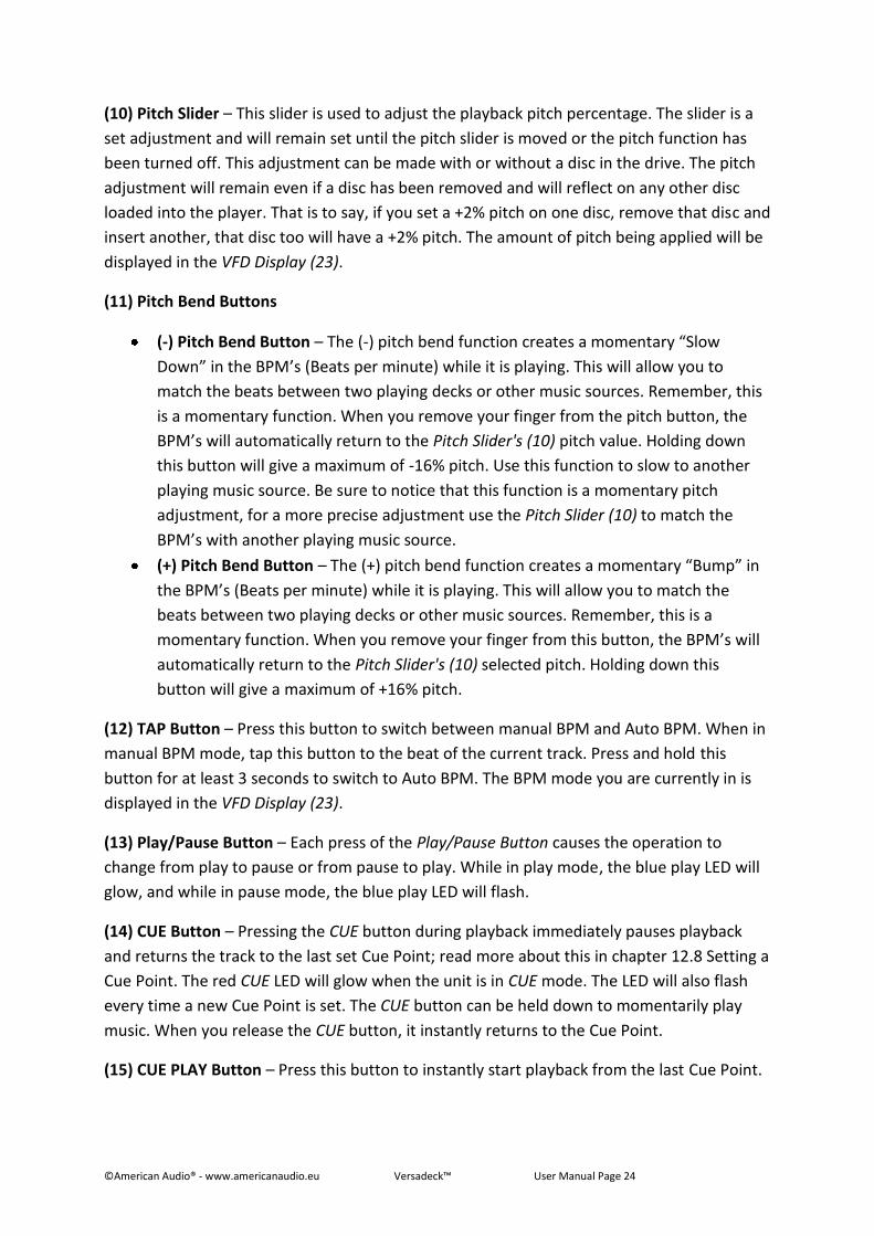
(10) Pitch Slider – This slider is used to adjust the playback pitch percentage. The slider is a
set adjustment and will remain set until the pitch slider is moved or the pitch function has
been turned off. This adjustment can be made with or without a disc in the drive. The pitch
adjustment will remain even if a disc has been removed and will reflect on any other disc
loaded into the player. That is to say, if you set a +2% pitch on one disc, remove that disc and
insert another, that disc too will have a +2% pitch. The amount of pitch being applied will be
displayed in the VFD Display (23).
(11) Pitch Bend Buttons
(-) Pitch Bend Button – The (-) pitch bend function creates a momentary “Slow
Down” in the BPM’s (Beats per minute) while it is playing. This will allow you to
match the beats between two playing decks or other music sources. Remember, this
is a momentary function. When you remove your finger from the pitch button, the
BPM’s will automatically return to the Pitch Slider's (10) pitch value. Holding down
this button will give a maximum of -16% pitch. Use this function to slow to another
playing music source. Be sure to notice that this function is a momentary pitch
adjustment, for a more precise adjustment use the Pitch Slider (10) to match the
BPM’s with another playing music source.
(+) Pitch Bend Button – The (+) pitch bend function creates a momentary “Bump” in
the BPM’s (Beats per minute) while it is playing. This will allow you to match the
beats between two playing decks or other music sources. Remember, this is a
momentary function. When you remove your finger from this button, the BPM’s will
automatically return to the Pitch Slider's (10) selected pitch. Holding down this
button will give a maximum of +16% pitch.
(12) TAP Button – Press this button to switch between manual BPM and Auto BPM. When in
manual BPM mode, tap this button to the beat of the current track. Press and hold this
button for at least 3 seconds to switch to Auto BPM. The BPM mode you are currently in is
displayed in the VFD Display (23).
(13) Play/Pause Button – Each press of the Play/Pause Button causes the operation to
change from play to pause or from pause to play. While in play mode, the blue play LED will
glow, and while in pause mode, the blue play LED will flash.
(14) CUE Button – Pressing the CUE button during playback immediately pauses playback
and returns the track to the last set Cue Point; read more about this in chapter 12.8 Setting a
Cue Point. The red CUE LED will glow when the unit is in CUE mode. The LED will also flash
every time a new Cue Point is set. The CUE button can be held down to momentarily play
music. When you release the CUE button, it instantly returns to the Cue Point.
(15) CUE PLAY Button – Press this button to instantly start playback from the last Cue Point.
©American Audio® - www.americanaudio.eu Versadeck™ User Manual Page 25
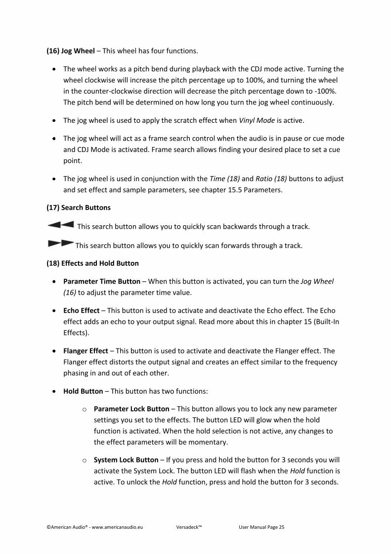
(16) Jog Wheel – This wheel has four functions.
The wheel works as a pitch bend during playback with the CDJ mode active. Turning the
wheel clockwise will increase the pitch percentage up to 100%, and turning the wheel
in the counter-clockwise direction will decrease the pitch percentage down to -100%.
The pitch bend will be determined on how long you turn the jog wheel continuously.
The jog wheel is used to apply the scratch effect when Vinyl Mode is active.
The jog wheel will act as a frame search control when the audio is in pause or cue mode
and CDJ Mode is activated. Frame search allows finding your desired place to set a cue
point.
The jog wheel is used in conjunction with the Time (18) and Ratio (18) buttons to adjust
and set effect and sample parameters, see chapter 15.5 Parameters.
(17) Search Buttons
This search button allows you to quickly scan backwards through a track.
This search button allows you to quickly scan forwards through a track.
(18) Effects and Hold Button
Parameter Time Button – When this button is activated, you can turn the Jog Wheel
(16) to adjust the parameter time value.
Echo Effect – This button is used to activate and deactivate the Echo effect. The Echo
effect adds an echo to your output signal. Read more about this in chapter 15 (Built-In
Effects).
Flanger Effect – This button is used to activate and deactivate the Flanger effect. The
Flanger effect distorts the output signal and creates an effect similar to the frequency
phasing in and out of each other.
Hold Button – This button has two functions:
o Parameter Lock Button – This button allows you to lock any new parameter
settings you set to the effects. The button LED will glow when the hold
function is activated. When the hold selection is not active, any changes to
the effect parameters will be momentary.
o System Lock Button – If you press and hold the button for 3 seconds you will
activate the System Lock. The button LED will flash when the Hold function is
active. To unlock the Hold function, press and hold the button for 3 seconds.
©American Audio® - www.americanaudio.eu Versadeck™ User Manual Page 26
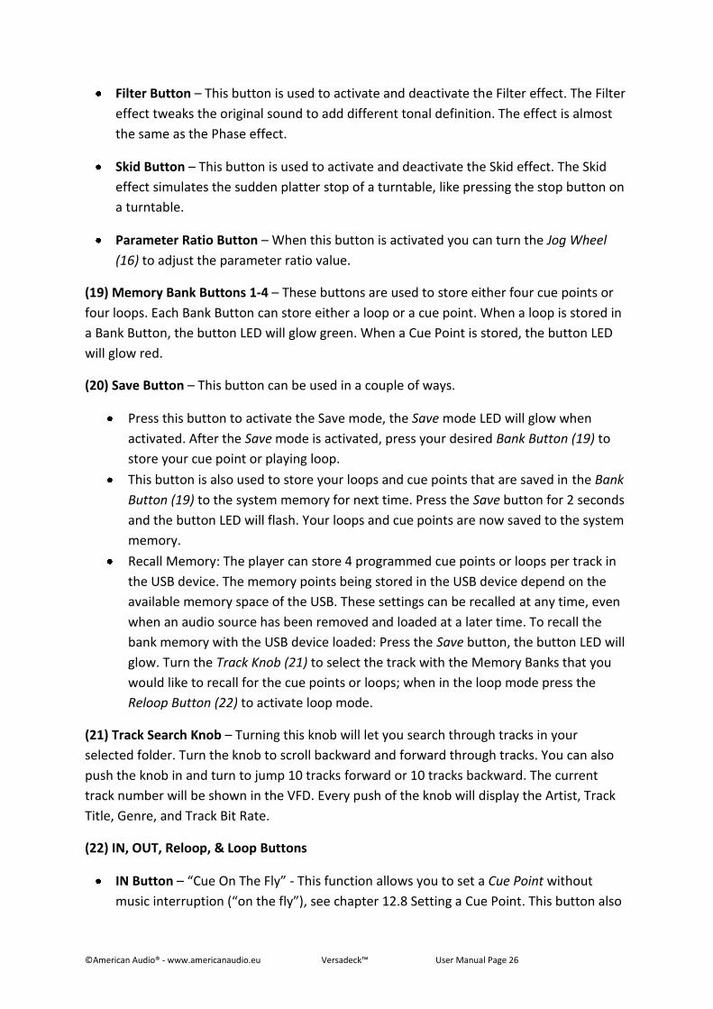
Filter Button – This button is used to activate and deactivate the Filter effect. The Filter
effect tweaks the original sound to add different tonal definition. The effect is almost
the same as the Phase effect.
Skid Button – This button is used to activate and deactivate the Skid effect. The Skid
effect simulates the sudden platter stop of a turntable, like pressing the stop button on
a turntable.
Parameter Ratio Button – When this button is activated you can turn the Jog Wheel
(16) to adjust the parameter ratio value.
(19) Memory Bank Buttons 1-4 – These buttons are used to store either four cue points or
four loops. Each Bank Button can store either a loop or a cue point. When a loop is stored in
a Bank Button, the button LED will glow green. When a Cue Point is stored, the button LED
will glow red.
(20) Save Button – This button can be used in a couple of ways.
Press this button to activate the Save mode, the Save mode LED will glow when
activated. After the Save mode is activated, press your desired Bank Button (19) to
store your cue point or playing loop.
This button is also used to store your loops and cue points that are saved in the Bank
Button (19) to the system memory for next time. Press the Save button for 2 seconds
and the button LED will flash. Your loops and cue points are now saved to the system
memory.
Recall Memory: The player can store 4 programmed cue points or loops per track in
the USB device. The memory points being stored in the USB device depend on the
available memory space of the USB. These settings can be recalled at any time, even
when an audio source has been removed and loaded at a later time. To recall the
bank memory with the USB device loaded: Press the Save button, the button LED will
glow. Turn the Track Knob (21) to select the track with the Memory Banks that you
would like to recall for the cue points or loops; when in the loop mode press the
Reloop Button (22) to activate loop mode.
(21) Track Search Knob – Turning this knob will let you search through tracks in your
selected folder. Turn the knob to scroll backward and forward through tracks. You can also
push the knob in and turn to jump 10 tracks forward or 10 tracks backward. The current
track number will be shown in the VFD. Every push of the knob will display the Artist, Track
Title, Genre, and Track Bit Rate.
(22) IN, OUT, Reloop, & Loop Buttons
IN Button – “Cue On The Fly” - This function allows you to set a Cue Point without
music interruption (“on the fly”), see chapter 12.8 Setting a Cue Point. This button also
©American Audio® - www.americanaudio.eu Versadeck™ User Manual Page 27
sets the starting point of a seamless loop, see chapter 12.9 Creating and Playing a
seamless Loop.
OUT Button – This button is used to set the ending point of a loop. A loop is started by
pressing the IN Button, pressing the OUT Button sets the loop ending point. The loop
will continue to play until the Out Button is pressed once again.
Reloop Button – If a seamless loop has been made, see chapter 12.9 Creating and
Playing a seamless Loop, but the player is not actively in seamless loop mode (a loop is
not playing), pressing the Reloop Button will instantly reactivate the seamless loop
mode. To exit loop, press the Out Button. “LOOP” will appear in the VFD Display (23)
when the Reloop function is available.
(23) VFD Display – This high quality VFD display indicates all the various functions, as they
are occurring. This display is viewable at several comfortable angles, see chapter 9 (Set-Up).
The display icons will be explained in chapter 10.5 VFD Display.
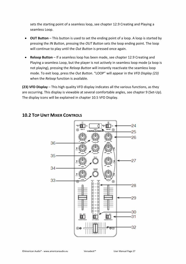
10.2 TOP UNIT MIXER CONTROLS
©American Audio® - www.americanaudio.eu Versadeck™ User Manual Page 28
(24) Source Selector Switch – These switches are used to select the input source assigned to
each channel. Each channel may only be assigned one input source at a time.
CH1 selected to PC + CH2 selected to PC – the entire unite works as a MIDI controller.
CH1 selected to PC + CH2 selected to DECK B – the Deck A works as a MIDI controller,
the mixer works internally with Deck B.
CH1 selected to PC + CH2 selected to LN2/ PH2 – the Deck A works as a MIDI
controller, the mixer works internally with LN2/PH2 input.
(25) USB PORT 1 – This is the first USB port where you can insert a USB stick, USB SD Card
reader, or compatible external hard drive for playback. Very Important: Please read chapter
9.1 USB Information for details regarding/using USB devices.
(26) Channel Gain Control – This adjustment is used to adjust an audio source signal input
gain for a channel. Never use the gain control to adjust output volume. Setting the gain level
properly will ensure a clean output signal. To properly set the gain level controls:
1. Be sure the Master Volume Control (36) is set to level 4.
2. Set the Channel Fader (29) to level 8.
3. Begin playback on an audio source connected to the channel you are adjusting.
4. Use the Gain Control (26) to adjust an average output volume of +4 dB.
5. Repeat this step for all channels
(27) Equalizer – All of the channels include a three-band signal EQ. These controls are used
to increase or decrease the LOW’s, MID’s, and HI’s of the output signal.
Treble Control – This knob is used to adjust the treble levels of a channel allowing for
a maximum treble gain of +10dB or maximum decrease of -35dB. Turning the knob in
a counter-clockwise direction will decrease the amount of treble applied to a channel
signal, turning the knob in a clockwise direction will increase the amount of treble
applied to a channel signal.
Midrange Control – This knob is used to adjust the midrange levels of a channel
allowing for a maximum midrange gain of +10dB or maximum decrease of -35dB.
Turning the knob in a counter-clockwise direction will decrease the amount of
midrange applied to a channel signal, turning the knob in a clockwise direction will
increase the amount of midrange applied to a channel signal.
Bass Control – This knob is used to adjust the low frequency levels of a channel
allowing for a maximum bass gain of +10dB or maximum signal decrease of -35dB.
Turning the knob in a counter-clockwise direction will decrease the amount of bass
©American Audio® - www.americanaudio.eu Versadeck™ User Manual Page 29
applied to a channel signal, turning the knob in a clockwise direction will increase the
amount of bass applied to a channel signal.
(28) Master Volume Level Indicators – The dual Master Level LED Indicators are used to
detail the master output level. The meters will detail the output level of both the left and
right channels.
(29) Channel Fader – These faders are used to control the output signal of any source
assigned to its particular channel.
(30) Crossfader Curve Adjustment – The 3 position switch changes the behavior of the
crossfader action by changing the crossover curve slope. The 3 settings from left to right are:
Quick Fade, Short Fade, and Normal Fade. (Quick Fade is usually used for scratching).
(31) Faderstart ON/OFF Switch – With this function you can use the crossfader to start and
stop playback. The ON/OFF Faderstart Switch activates the fader start feature. When the
fader start feature is activated, sliding the Crossfader (32) from left to right will play or cue
the player. Example: Be sure the Faderstart feature is activated on both channels. Slide the
crossfader to the channel 1 position (full left) and begin playback on Player 1. Slide the
crossfader to the channel 2 position (far right). This will immediately trigger the play function
on Player 2 and return Player 1 to cue mode. To return to normal fader operation, turn the
Faderstart ON/OFF Switch to the Off position.
(32) Replaceable Crossfader – This fader is used to blend the output signals of channels 1
and 2 together. When the fader is in the full left position (channel 1), the output signal of
channel 1 will be controlled by the master volume level. The same fundamentals will apply
for channel 2. Sliding the fader from one position to another will vary the output signals of
channels 1 and 2 respectively. When the crossfader is set in the center position, the output
signals of both the channels one and channels two will be even.
(33) Master Indicator Button – This button is used to choose between master level
indicators and channel level indicators.
(34) Relay Button – This button activates the Relay function.
(35) Booth Level – This knob is used to adjust the monitor volume output level. Turn the
knob in a clockwise direction to increase the monitor volume.
(36) Master Volume Control – This rotary knob is used to control the master output level
(volume). To avoid distorted output, try to maintain an average output signal level +4 dB. Be
sure this volume control is always set to zero before turning the unit on.
©American Audio® - www.americanaudio.eu Versadeck™ User Manual Page 30
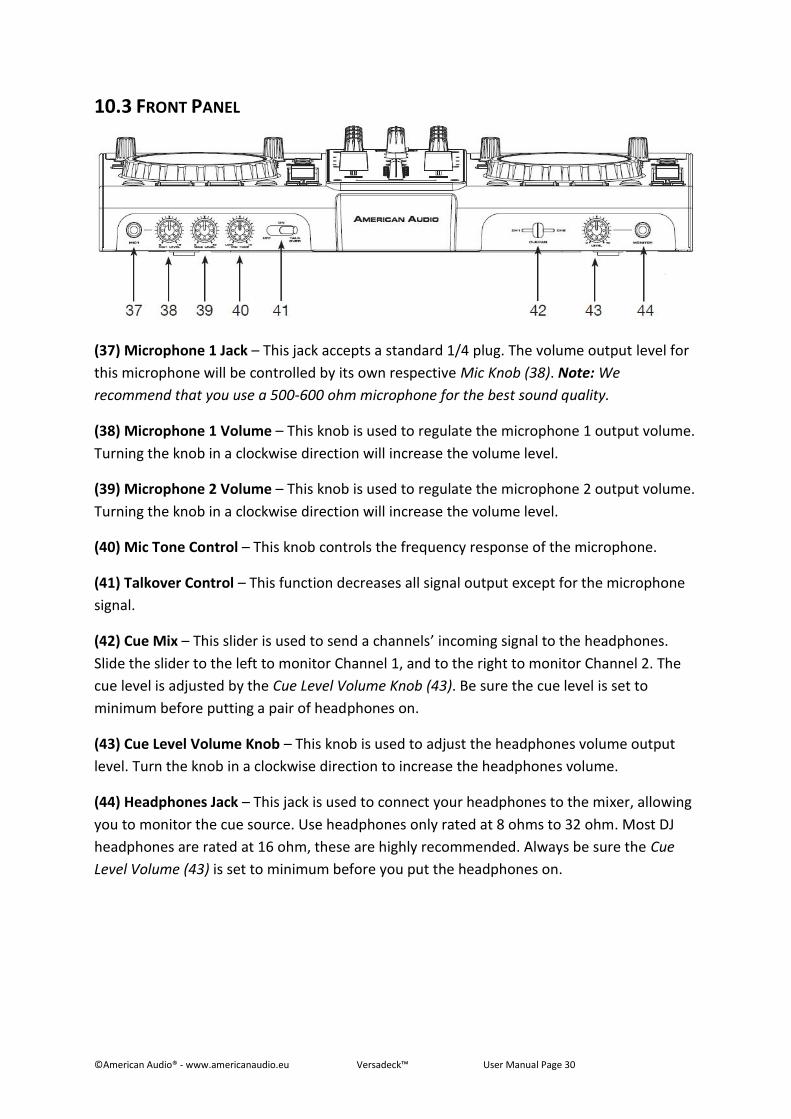
10.3 FRONT PANEL
(37) Microphone 1 Jack – This jack accepts a standard 1/4 plug. The volume output level for
this microphone will be controlled by its own respective Mic Knob (38). Note: We
recommend that you use a 500-600 ohm microphone for the best sound quality.
(38) Microphone 1 Volume – This knob is used to regulate the microphone 1 output volume.
Turning the knob in a clockwise direction will increase the volume level.
(39) Microphone 2 Volume – This knob is used to regulate the microphone 2 output volume.
Turning the knob in a clockwise direction will increase the volume level.
(40) Mic Tone Control – This knob controls the frequency response of the microphone.
(41) Talkover Control – This function decreases all signal output except for the microphone
signal.
(42) Cue Mix – This slider is used to send a channels’ incoming signal to the headphones.
Slide the slider to the left to monitor Channel 1, and to the right to monitor Channel 2. The
cue level is adjusted by the Cue Level Volume Knob (43). Be sure the cue level is set to
minimum before putting a pair of headphones on.
(43) Cue Level Volume Knob – This knob is used to adjust the headphones volume output
level. Turn the knob in a clockwise direction to increase the headphones volume.
(44) Headphones Jack – This jack is used to connect your headphones to the mixer, allowing
you to monitor the cue source. Use headphones only rated at 8 ohms to 32 ohm. Most DJ
headphones are rated at 16 ohm, these are highly recommended. Always be sure the Cue
Level Volume (43) is set to minimum before you put the headphones on.
©American Audio® - www.americanaudio.eu Versadeck™ User Manual Page 31
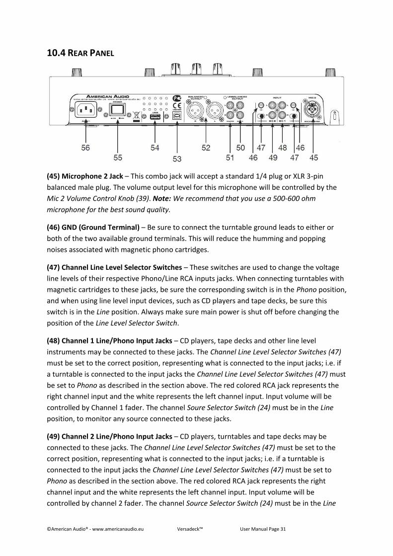
10.4 REAR PANEL
(45) Microphone 2 Jack – This combo jack will accept a standard 1/4 plug or XLR 3-pin
balanced male plug. The volume output level for this microphone will be controlled by the
Mic 2 Volume Control Knob (39). Note: We recommend that you use a 500-600 ohm
microphone for the best sound quality.
(46) GND (Ground Terminal) – Be sure to connect the turntable ground leads to either or
both of the two available ground terminals. This will reduce the humming and popping
noises associated with magnetic phono cartridges.
(47) Channel Line Level Selector Switches – These switches are used to change the voltage
line levels of their respective Phono/Line RCA inputs jacks. When connecting turntables with
magnetic cartridges to these jacks, be sure the corresponding switch is in the Phono position,
and when using line level input devices, such as CD players and tape decks, be sure this
switch is in the Line position. Always make sure main power is shut off before changing the
position of the Line Level Selector Switch.
(48) Channel 1 Line/Phono Input Jacks – CD players, tape decks and other line level
instruments may be connected to these jacks. The Channel Line Level Selector Switches (47)
must be set to the correct position, representing what is connected to the input jacks; i.e. if
a turntable is connected to the input jacks the Channel Line Level Selector Switches (47) must
be set to Phono as described in the section above. The red colored RCA jack represents the
right channel input and the white represents the left channel input. Input volume will be
controlled by Channel 1 fader. The channel Soure Selector Switch (24) must be in the Line
position, to monitor any source connected to these jacks.
(49) Channel 2 Line/Phono Input Jacks – CD players, turntables and tape decks may be
connected to these jacks. The Channel Line Level Selector Switches (47) must be set to the
correct position, representing what is connected to the input jacks; i.e. if a turntable is
connected to the input jacks the Channel Line Level Selector Switches (47) must be set to
Phono as described in the section above. The red colored RCA jack represents the right
channel input and the white represents the left channel input. Input volume will be
controlled by channel 2 fader. The channel Source Selector Switch (24) must be in the Line
©American Audio® - www.americanaudio.eu Versadeck™ User Manual Page 32
position when CD players and any other line level instruments are connected to these jacks,
to monitor any source connected to these jacks.
(50) Booth Output Jacks – The Versadeck™ offers a secondary output usually used to
monitor your mix or to route to an outboard recording device. This output volume is
controlled by the Booth Level Knob (35).
(51) RCA Master Outputs –The RCA jacks send a low current unbalanced output signal.
These jacks should only be used for shorter cable runs to signal processors or looping to
another mixer. For cable runs greater than 15 feet use the XLR Balanced Jacks (52).
(52) Balanced XLR Master Output Jacks – The Master Output includes a pair of XLR Balanced
jacks as well as a pair of RCA Unbalanced Jacks (51). The 3-pin XLR jacks send a high current
balanced output signal. These jacks should be used when you will be driving an amp or other
audio equipment with a balanced input, or whenever you will be running a signal line greater
than 15 feet. Always use these jacks whenever possible.
(53) USB MIDI Jack – Use this jack to connect to a computer or a host USB player. After
hooking up your computer with the USB 1.1 connections, your computer will detect them
respectively as an external sound card (USB Code). You may either play music on your
computer or send it via the USB 1.1 connections as a signal source to the device;
alternatively, you may record the Master output signal on your computer using the USB 1.1
connection. Note: The sent Master Output Signal is not influenced by the position of the
volume controls. To use the USB 1.1 connection, please also refer to the operation manual of
your computer and the programs used.
(54) USB PORT 2 – This is the second USB port where you can insert a USB stick, USB SD Card
reader, or compatible external hard drive for playback. Very important: Please read chapter
9.1 USB Information for details regarding/using USB devices.
(55) Power Button – This button is used to turn your unit’s power on and off.
(56) Power Connector – This connection is used to connect your main power. Be sure that
your local power matches the unit’s required power. NEVER REMOVE THE GROUND PRONG
FROM THE POWER CABLE; DOING SO MAY RESULT IN IMPROPER OPERATION.
©American Audio® - www.americanaudio.eu Versadeck™ User Manual Page 33
10.5 VFD DISPLAY
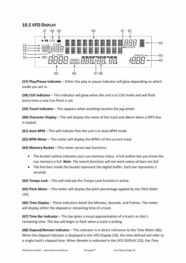
(57) Play/Pause Indicator – Either the play or pause indicator will glow depending on which
mode you are in.
(58) CUE Indicator – This indicator will glow when the unit is in CUE mode and will flash
every time a new Cue Point is set.
(59) Touch Indicator – This appears when anything touches the jog wheel.
(60) Character Display – This will display the name of the track and album when a MP3 disc
is loaded.
(61) Auto BPM – This will indicate that the unit is in Auto BPM mode.
(62) BPM Meter – This meter will display the BPM's of the current track.
(63) Memory Bucket – This meter serves two functions.
The bucket outline indicates your cue memory status. A full outline lets you know the
cue memory is full. Note: The search functions will not work unless all bars are full.
The five bars inside the bucket represent the digital buffer. Each bar represents 2
seconds.
(64) Tempo Lock – This will indicate the Tempo Lock function is active.
(65) Pitch Meter – This meter will display the pitch percentage applied by the Pitch Slider
(10).
(66) Time Display – These indicators detail the Minutes, Seconds, and Frames. The meter
will display either the elapsed or remaining time of a track.
(67) Time Bar Indicator – This bar gives a visual approximation of a track's or disc's
remaining time. This bar will begin to flash when a track is ending.
(68) Elapsed/Remain Indicator – This indicator is in direct reference to the Time Meter (66).
When the Elapsed indicator is displayed in the VFD Display (23), the time defined will refer to
a single track's elapsed time. When Remain is indicated in the VFD DISPLAY (23), the Time
©American Audio® - www.americanaudio.eu Versadeck™ User Manual Page 34
Display (66) in the VFD will define the current track's remaining time. The time mode is
changed by the tapping on the Time Button (8).
(69) Track Indicator – This indicator details the current track. The number displayed in the
track indicator is a direct reference to the track in Play, Pause, or CUE mode.
(70) MP3 Indicator – This will indicate that MP3 files have been detected on the loaded USB
device.
(71) Folder Indicator – This indicator details the current folder you are in.
(72) Single Indicator – This indicates that the player is in Single Play Mode, the track will play
once and return to CUE mode. If the single indicator is not on, the unit is in continuous
mode. In continuous mode the drive will play all the remaining tracks.
(73) Reloop Indicactor – Appears when a loop is engaged or ready to be engaged.
(74) Auto CUE – This will indicate if the Auto Cue is on or off. Press and hold the SGL/CTN (7)
for 1 second, to turn the Auto Cue function on and off.
©American Audio® - www.americanaudio.eu Versadeck™ User Manual Page 35
11. INTERNAL MENU Press the Folder Knob (1) for at least 3 seconds to enter the internal menu. Turn the Folder
Knob (1) to scroll through the different submenus. Turn either the Track Knob (21) or Jog
Wheel (16) to change the submenu settings.
To save and exit the internal menu, turn the Folder Knob (1) until G. Exit & Save is displayed,
then press the Track Knob (21) to save your settings. If your settings were saved correctly,
Saving will appear briefly in the VFD Display (23).
NOTE: You can exit the internal menu anytime you want by pressing the Folder Knob (1),
however your modified settings will not be saved.
1. Playlist – Normal / Title/ Artist / Album / Genre
o The Database Builder can generate a playlist for USB devices. You can adjust
various criteria in order to filter tracks in this setting. You can turn the Track
Knob (21) or Jog Wheel (16) to scroll through the different settings; Normal /
Title/ Artist / Album / Genre. Read more about this in chapter 16 (Playlist
Operation).
2. Repeat Mode – 3 different modes: Play All Repeat / Folder Repeat / Track Repeat
3. MIDI CH – Setup MIDI Channel from 1 to 16 (Deck A - Mixer - Deck B).
4. MIDI Setup
o TAP = Hold/Toggle
o I/O = Hide/DIS. (Hide/Display MIDI I/O value)
5. Crossfader
o LOCK = To lock the crossfader in the middle of the two channels
o UNLOCK = The crossfader is back to normal status
6. Crossfader Reverse
o ON = Reverse the crossfader
o OFF = Normal Mode
7. Display Time – 0.5 ~ 12.0 secs. (Line name start/stop time adjustment)
8. Scroll Speed – 50 ~ 2000 msecs. (Adjust the scroll speed of the character display)
9. Sensitivity – Touch Wheel Sensitivity adjustment (Adjustment range is -20 ~ +20)
A. INTENSITY – VFD Brightness (Brightness Range is 1 ~ 4)
B. A.CUE LEVEL – Change the Auto CUE level (Level range is -36 ~ -78dB)
C. LINE SETUP – Select VFD line name and display
D. BIT RATE – Display ON/OFF
E. VERSION – CXX (Control Version) DSPXX (DSP Version)
F. LOAD DEFAULTS – Press the Track Knob (21) to change all settings back to default.
G. EXIT & SAVE – Exit & Save your custom settings until you power down. Press the
Track Knob (21) to exit & save.
©American Audio® - www.americanaudio.eu Versadeck™ User Manual Page 36
NOTE:
SAVE: U1/U2, PITCH ON/OFF, PITCH RANGE, SGL/CTN, AUTO CUE, TIME MODE, HOLD, KEY
LOCK, EFFECTS ON/OFF, PLAYLIST, REPEAT MODE, MIDI CHANNEL, MIDI SETUP,
CROSSFADER, CROSSFADER REVERSE, DISPLAY TIME, SCROLL SPEED, SENSITIVITY, INTENSITY,
A.CUE LEVEL, DISPLAY
DEFAULTS: U1/U2 (U1), PITCH (OFF), PITCH RANGE (10%), SGL,CTN (CTN), AUTO CUE (ON),
TIME MODE (REMAIN), HOLD (OFF), KEY LOCK (OFF), EFFECTS (OFF), PLAYLIST (NORMAL),
REPEAT MODE (ALL), MIDI CHANNEL (1-2-3), MIDI SETUP (TAP=HOLD, I/O=HIDE),
CROSSFADER (UNLOCK) CROSSFADER REVERSE (OFF), DISPLAY TIME (3sec.), SCROLL SPEED
(400ms), SENSITIVITY (0), INTENSITY (4), A.CUE LEVEL (-48dB), BIT RATE DISPLAY (ON)
©American Audio® - www.americanaudio.eu Versadeck™ User Manual Page 37
12. BASIC OPERATIONS
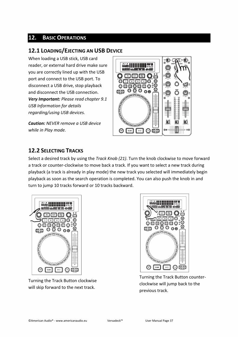
12.1 LOADING/EJECTING AN USB DEVICE When loading a USB stick, USB card
reader, or external hard drive make sure
you are correctly lined up with the USB
port and connect to the USB port. To
disconnect a USB drive, stop playback
and disconnect the USB connection.
Very Important: Please read chapter 9.1
USB Information for details
regarding/using USB devices.
Caution: NEVER remove a USB device
while in Play mode.
12.2 SELECTING TRACKS Select a desired track by using the Track Knob (21). Turn the knob clockwise to move forward
a track or counter-clockwise to move back a track. If you want to select a new track during
playback (a track is already in play mode) the new track you selected will immediately begin
playback as soon as the search operation is completed. You can also push the knob in and
turn to jump 10 tracks forward or 10 tracks backward.
Turning the Track Button clockwise
will skip forward to the next track.
Turning the Track Button counter-
clockwise will jump back to the
previous track.
©American Audio® - www.americanaudio.eu Versadeck™ User Manual Page 38
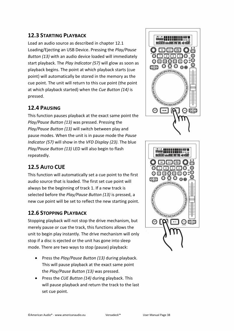
12.3 STARTING PLAYBACK Load an audio source as described in chapter 12.1
Loading/Ejecting an USB Device. Pressing the Play/Pause
Button (13) with an audio device loaded will immediately
start playback. The Play Indicator (57) will glow as soon as
playback begins. The point at which playback starts (cue
point) will automatically be stored in the memory as the
cue point. The unit will return to this cue point (the point
at which playback started) when the Cue Button (14) is
pressed.
12.4 PAUSING This function pauses playback at the exact same point the
Play/Pause Button (13) was pressed. Pressing the
Play/Pause Button (13) will switch between play and
pause modes. When the unit is in pause mode the Pause
Indicator (57) will show in the VFD Display (23). The blue
Play/Pause Button (13) LED will also begin to flash
repeatedly.
12.5 AUTO CUE This function will automatically set a cue point to the first
audio source that is loaded. The first set cue point will
always be the beginning of track 1. If a new track is
selected before the Play/Pause Button (13) is pressed, a
new cue point will be set to reflect the new starting point.
12.6 STOPPING PLAYBACK Stopping playback will not stop the drive mechanism, but
merely pause or cue the track, this functions allows the
unit to begin play instantly. The drive mechanism will only
stop if a disc is ejected or the unit has gone into sleep
mode. There are two ways to stop (pause) playback:
Press the Play/Pause Button (13) during playback.
This will pause playback at the exact same point
the Play/Pause Button (13) was pressed.
Press the CUE Button (14) during playback. This
will pause playback and return the track to the last
set cue point.
©American Audio® - www.americanaudio.eu Versadeck™ User Manual Page 39
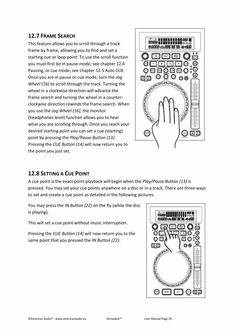
12.7 FRAME SEARCH This feature allows you to scroll through a track
frame by frame, allowing you to find and set a
starting cue or loop point. To use the scroll function
you must first be in pause mode, see chapter 12.4
Pausing, or cue mode, see chapter 12.5 Auto CUE.
Once you are in pause or cue mode, turn the Jog
Wheel (16) to scroll through the track. Turning the
wheel in a clockwise direction will advance the
frame search and turning the wheel in a counter-
clockwise direction rewinds the frame search. When
you use the Jog Wheel (16), the monitor
(headphones level) function allows you to hear
what you are scrolling through. Once you reach your
desired starting point you can set a cue (starting)
point by pressing the Play/Pause Button (13).
Pressing the CUE Button (14) will now return you to
the point you just set.
12.8 SETTING A CUE POINT A cue point is the exact point playback will begin when the Play/Pause Button (13) is
pressed. You may set your cue points anywhere on a disc or in a track. There are three ways
to set and create a cue point as detailed in the following pictures.
You may press the IN Button (22) on the fly (while the disc
is playing).
This will set a cue point without music interruption.
Pressing the CUE Button (14) will now return you to the
same point that you pressed the IN Button (22).
©American Audio® - www.americanaudio.eu Versadeck™ User Manual Page 40
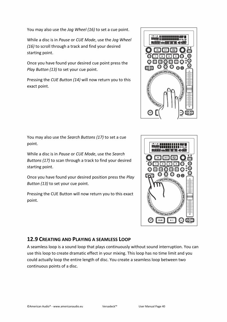
You may also use the Jog Wheel (16) to set a cue point.
While a disc is in Pause or CUE Mode, use the Jog Wheel
(16) to scroll through a track and find your desired
starting point.
Once you have found your desired cue point press the
Play Button (13) to set your cue point.
Pressing the CUE Button (14) will now return you to this
exact point.
You may also use the Search Buttons (17) to set a cue
point.
While a disc is in Pause or CUE Mode, use the Search
Buttons (17) to scan through a track to find your desired
starting point.
Once you have found your desired position press the Play
Button (13) to set your cue point.
Pressing the CUE Button will now return you to this exact
point.
12.9 CREATING AND PLAYING A SEAMLESS LOOP A seamless loop is a sound loop that plays continuously without sound interruption. You can
use this loop to create dramatic effect in your mixing. This loop has no time limit and you
could actually loop the entire length of disc. You create a seamless loop between two
continuous points of a disc.
©American Audio® - www.americanaudio.eu Versadeck™ User Manual Page 41
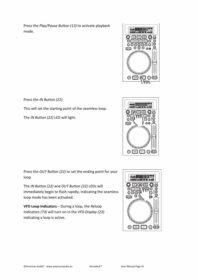
Press the Play/Pause Button (13) to activate playback
mode.
Press the IN Button (22).
This will set the starting point of the seamless loop.
The IN Button (22) LED will light.
Press the OUT Button (22) to set the ending point for your
loop.
The IN Button (22) and OUT Button (22) LEDs will
immediately begin to flash rapidly, indicating the seamless
loop mode has been activated.
VFD Loop Indicators – During a loop, the Reloop
Indicators (73) will turn on in the VFD Display (23)
indicating a loop is active.
©American Audio® - www.americanaudio.eu Versadeck™ User Manual Page 42
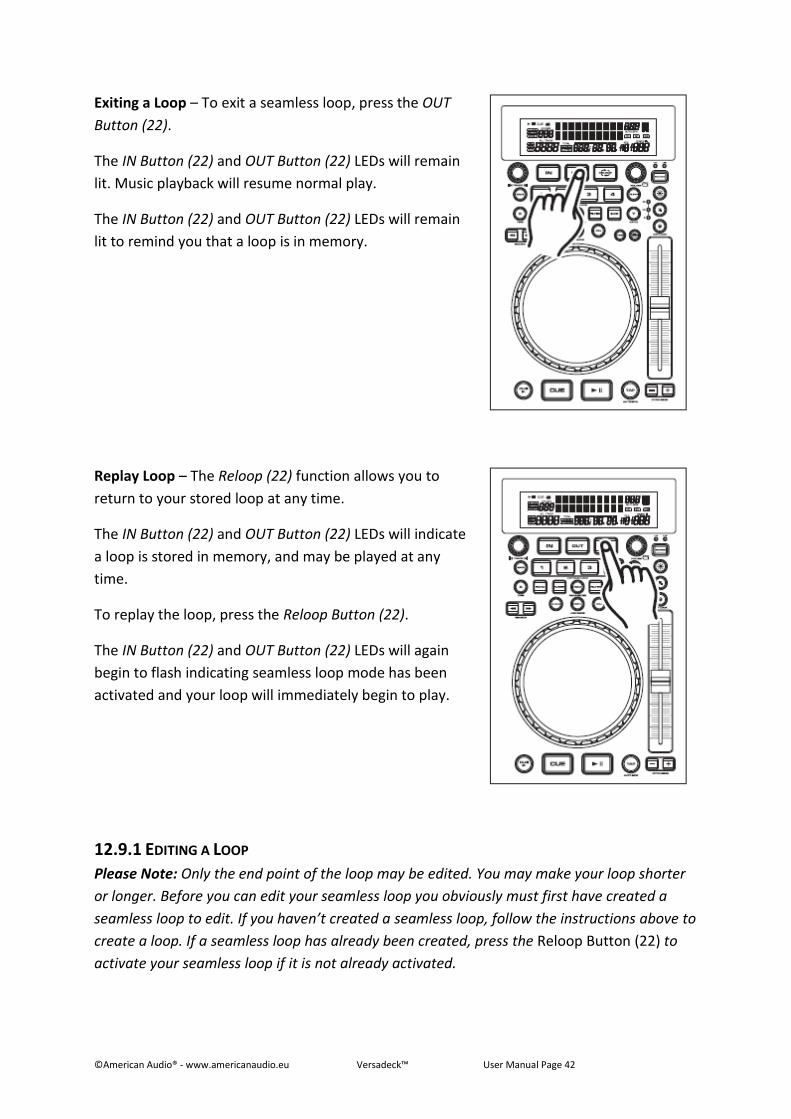
Exiting a Loop – To exit a seamless loop, press the OUT
Button (22).
The IN Button (22) and OUT Button (22) LEDs will remain
lit. Music playback will resume normal play.
The IN Button (22) and OUT Button (22) LEDs will remain
lit to remind you that a loop is in memory.
Replay Loop – The Reloop (22) function allows you to
return to your stored loop at any time.
The IN Button (22) and OUT Button (22) LEDs will indicate
a loop is stored in memory, and may be played at any
time.
To replay the loop, press the Reloop Button (22).
The IN Button (22) and OUT Button (22) LEDs will again
begin to flash indicating seamless loop mode has been
activated and your loop will immediately begin to play.
12.9.1 EDITING A LOOP
Please Note: Only the end point of the loop may be edited. You may make your loop shorter
or longer. Before you can edit your seamless loop you obviously must first have created a
seamless loop to edit. If you haven’t created a seamless loop, follow the instructions above to
create a loop. If a seamless loop has already been created, press the Reloop Button (22) to
activate your seamless loop if it is not already activated.
©American Audio® - www.americanaudio.eu Versadeck™ User Manual Page 43
To edit your seamless loop’s ending point, proceed as follows:
Press the OUT Button (22) to return to normal play. This will disengage the seamless
loop mode and allows you to edit the loops ending point.
Press the OUT Button (22) again when you reach your new ending point.
o For a shorter Loop: Press the OUT Button (22) at a sooner point in the track.
o For a longer Loop: Press the OUT Button (22) at a later point in the track.
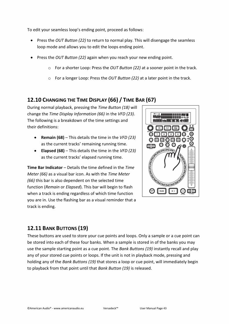
12.10 CHANGING THE TIME DISPLAY (66) / TIME BAR (67) During normal playback, pressing the Time Button (18) will
change the Time Display Information (66) in the VFD (23).
The following is a breakdown of the time settings and
their definitions:
Remain (68) – This details the time in the VFD (23)
as the current tracks’ remaining running time.
Elapsed (68) – This details the time in the VFD (23)
as the current tracks’ elapsed running time.
Time Bar Indicator – Details the time defined in the Time
Meter (66) as a visual bar icon. As with the Time Meter
(66) this bar is also dependent on the selected time
function (Remain or Elapsed). This bar will begin to flash
when a track is ending regardless of which time function
you are in. Use the flashing bar as a visual reminder that a
track is ending.
12.11 BANK BUTTONS (19) These buttons are used to store your cue points and loops. Only a sample or a cue point can
be stored into each of these four banks. When a sample is stored in of the banks you may
use the sample starting point as a cue point. The Bank Buttons (19) instantly recall and play
any of your stored cue points or loops. If the unit is not in playback mode, pressing and
holding any of the Bank Buttons (19) that stores a loop or cue point, will immediately begin
to playback from that point until that Bank Button (19) is released.
©American Audio® - www.americanaudio.eu Versadeck™ User Manual Page 44
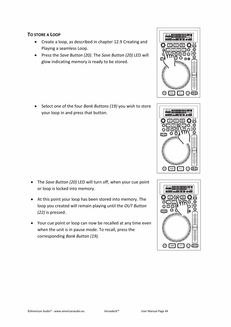
TO STORE A LOOP
Create a loop, as described in chapter 12.9 Creating and
Playing a seamless Loop.
Press the Save Button (20). The Save Button (20) LED will
glow indicating memory is ready to be stored.
Select one of the four Bank Buttons (19) you wish to store
your loop in and press that button.
The Save Button (20) LED will turn off, when your cue point
or loop is locked into memory.
At this point your loop has been stored into memory. The
loop you created will remain playing until the OUT Button
(22) is pressed.
Your cue point or loop can now be recalled at any time even
when the unit is in pause mode. To recall, press the
corresponding Bank Button (19).
©American Audio® - www.americanaudio.eu Versadeck™ User Manual Page 45
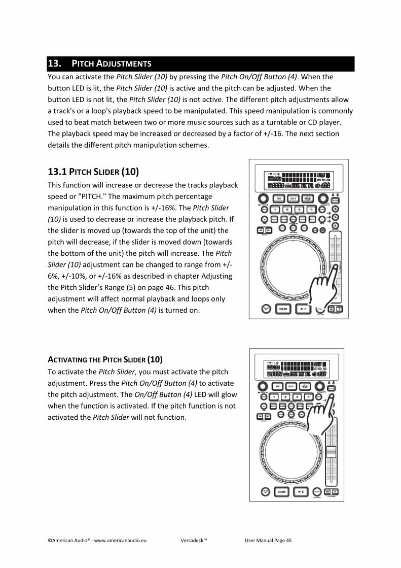
13. PITCH ADJUSTMENTS You can activate the Pitch Slider (10) by pressing the Pitch On/Off Button (4). When the
button LED is lit, the Pitch Slider (10) is active and the pitch can be adjusted. When the
button LED is not lit, the Pitch Slider (10) is not active. The different pitch adjustments allow
a track's or a loop's playback speed to be manipulated. This speed manipulation is commonly
used to beat match between two or more music sources such as a turntable or CD player.
The playback speed may be increased or decreased by a factor of +/-16. The next section
details the different pitch manipulation schemes.
13.1 PITCH SLIDER (10) This function will increase or decrease the tracks playback
speed or "PITCH." The maximum pitch percentage
manipulation in this function is +/-16%. The Pitch Slider
(10) is used to decrease or increase the playback pitch. If
the slider is moved up (towards the top of the unit) the
pitch will decrease, if the slider is moved down (towards
the bottom of the unit) the pitch will increase. The Pitch
Slider (10) adjustment can be changed to range from +/-
6%, +/-10%, or +/-16% as described in chapter Adjusting
the Pitch Slider’s Range (5) on page 46. This pitch
adjustment will affect normal playback and loops only
when the Pitch On/Off Button (4) is turned on.
ACTIVATING THE PITCH SLIDER (10)
To activate the Pitch Slider, you must activate the pitch
adjustment. Press the Pitch On/Off Button (4) to activate
the pitch adjustment. The On/Off Button (4) LED will glow
when the function is activated. If the pitch function is not
activated the Pitch Slider will not function.
©American Audio® - www.americanaudio.eu Versadeck™ User Manual Page 46
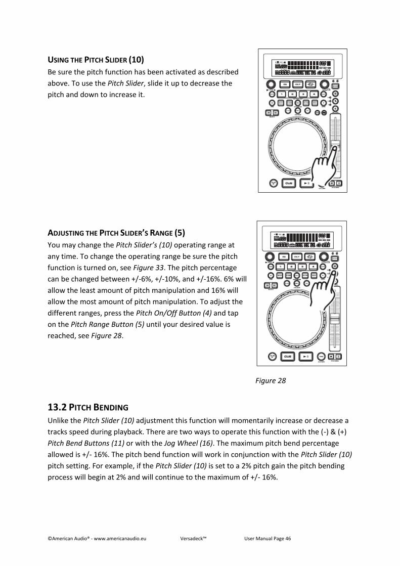
USING THE PITCH SLIDER (10)
Be sure the pitch function has been activated as described
above. To use the Pitch Slider, slide it up to decrease the
pitch and down to increase it.
ADJUSTING THE PITCH SLIDER’S RANGE (5)
You may change the Pitch Slider’s (10) operating range at
any time. To change the operating range be sure the pitch
function is turned on, see Figure 33. The pitch percentage
can be changed between +/-6%, +/-10%, and +/-16%. 6% will
allow the least amount of pitch manipulation and 16% will
allow the most amount of pitch manipulation. To adjust the
different ranges, press the Pitch On/Off Button (4) and tap
on the Pitch Range Button (5) until your desired value is
reached, see Figure 28.
Figure 28
13.2 PITCH BENDING Unlike the Pitch Slider (10) adjustment this function will momentarily increase or decrease a
tracks speed during playback. There are two ways to operate this function with the (-) & (+)
Pitch Bend Buttons (11) or with the Jog Wheel (16). The maximum pitch bend percentage
allowed is +/- 16%. The pitch bend function will work in conjunction with the Pitch Slider (10)
pitch setting. For example, if the Pitch Slider (10) is set to a 2% pitch gain the pitch bending
process will begin at 2% and will continue to the maximum of +/- 16%.
©American Audio® - www.americanaudio.eu Versadeck™ User Manual Page 47
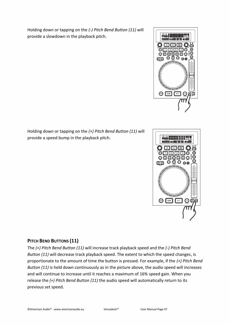
Holding down or tapping on the (-) Pitch Bend Button (11) will
provide a slowdown in the playback pitch.
Holding down or tapping on the (+) Pitch Bend Button (11) will
provide a speed bump in the playback pitch.
PITCH BEND BUTTONS (11)
The (+) Pitch Bend Button (11) will increase track playback speed and the (-) Pitch Bend
Button (11) will decrease track playback speed. The extent to which the speed changes, is
proportionate to the amount of time the button is pressed. For example, if the (+) Pitch Bend
Button (11) is held down continuously as in the picture above, the audio speed will increases
and will continue to increase until it reaches a maximum of 16% speed gain. When you
release the (+) Pitch Bend Button (11) the audio speed will automatically return to its
previous set speed.
©American Audio® - www.americanaudio.eu Versadeck™ User Manual Page 48
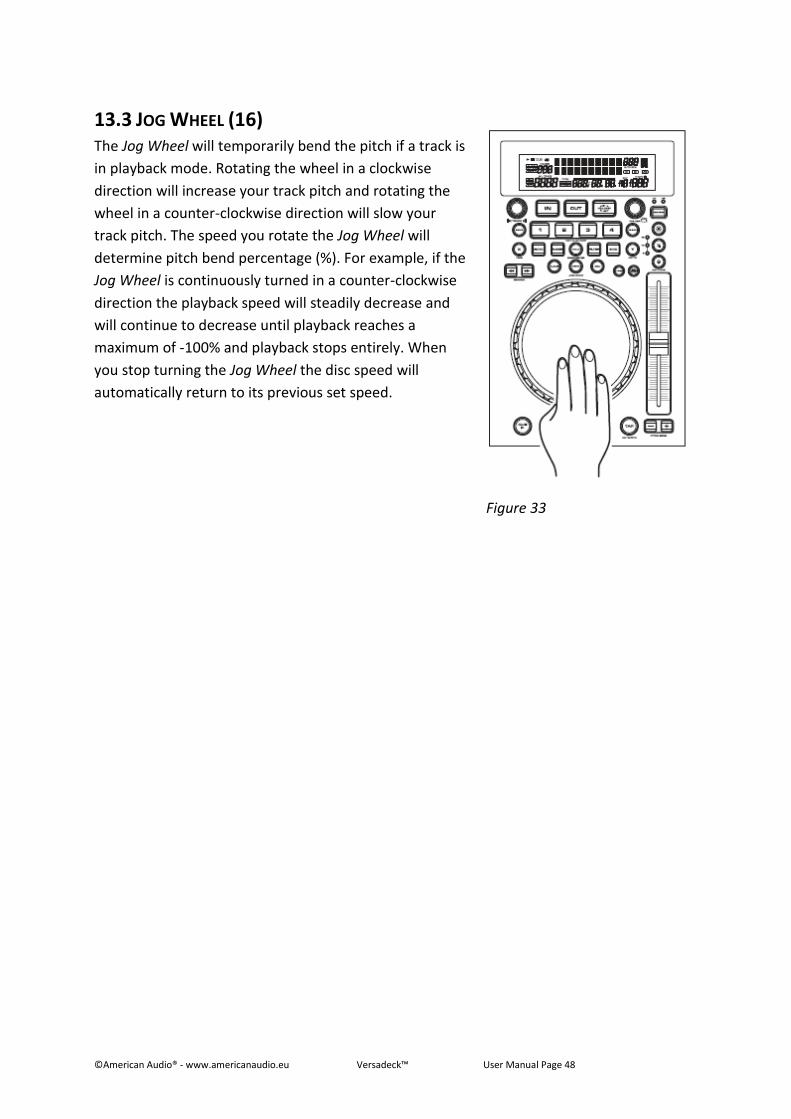
13.3 JOG WHEEL (16) The Jog Wheel will temporarily bend the pitch if a track is
in playback mode. Rotating the wheel in a clockwise
direction will increase your track pitch and rotating the
wheel in a counter-clockwise direction will slow your
track pitch. The speed you rotate the Jog Wheel will
determine pitch bend percentage (%). For example, if the
Jog Wheel is continuously turned in a counter-clockwise
direction the playback speed will steadily decrease and
will continue to decrease until playback reaches a
maximum of -100% and playback stops entirely. When
you stop turning the Jog Wheel the disc speed will
automatically return to its previous set speed.
Figure 33
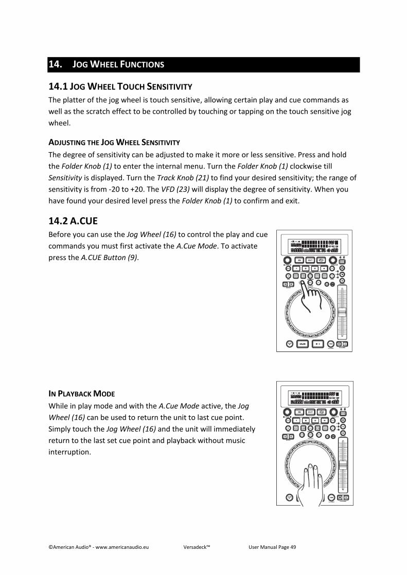
©American Audio® - www.americanaudio.eu Versadeck™ User Manual Page 49
14. JOG WHEEL FUNCTIONS
14.1 JOG WHEEL TOUCH SENSITIVITY The platter of the jog wheel is touch sensitive, allowing certain play and cue commands as
well as the scratch effect to be controlled by touching or tapping on the touch sensitive jog
wheel.
ADJUSTING THE JOG WHEEL SENSITIVITY
The degree of sensitivity can be adjusted to make it more or less sensitive. Press and hold
the Folder Knob (1) to enter the internal menu. Turn the Folder Knob (1) clockwise till
Sensitivity is displayed. Turn the Track Knob (21) to find your desired sensitivity; the range of
sensitivity is from -20 to +20. The VFD (23) will display the degree of sensitivity. When you
have found your desired level press the Folder Knob (1) to confirm and exit.
14.2 A.CUE Before you can use the Jog Wheel (16) to control the play and cue
commands you must first activate the A.Cue Mode. To activate
press the A.CUE Button (9).
IN PLAYBACK MODE
While in play mode and with the A.Cue Mode active, the Jog
Wheel (16) can be used to return the unit to last cue point.
Simply touch the Jog Wheel (16) and the unit will immediately
return to the last set cue point and playback without music
interruption.
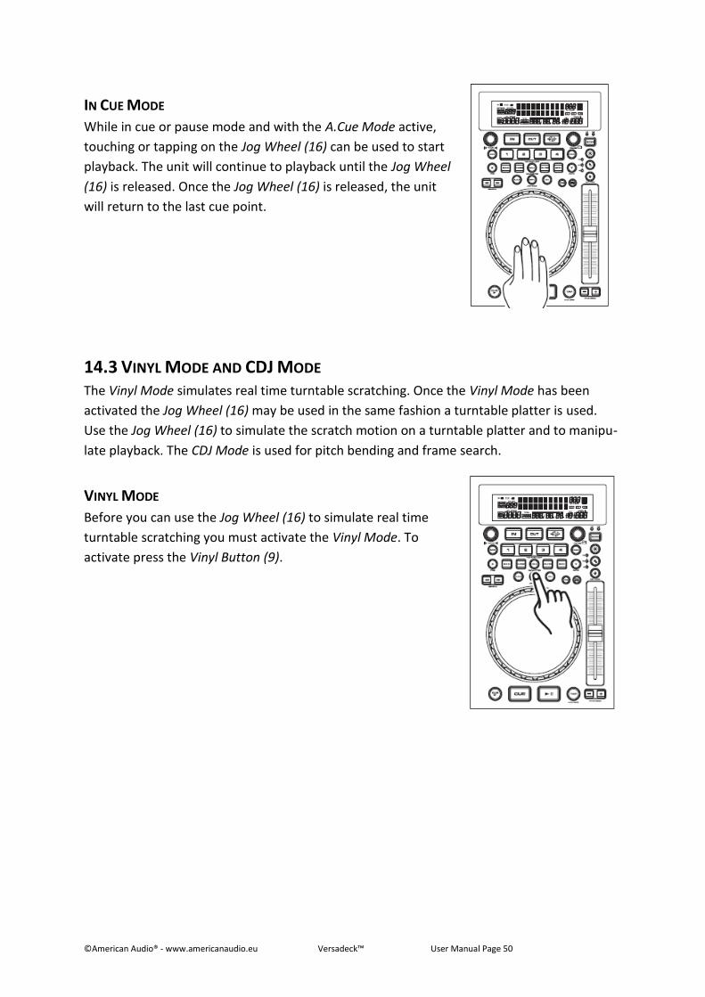
©American Audio® - www.americanaudio.eu Versadeck™ User Manual Page 50
IN CUE MODE
While in cue or pause mode and with the A.Cue Mode active,
touching or tapping on the Jog Wheel (16) can be used to start
playback. The unit will continue to playback until the Jog Wheel
(16) is released. Once the Jog Wheel (16) is released, the unit
will return to the last cue point.
14.3 VINYL MODE AND CDJ MODE The Vinyl Mode simulates real time turntable scratching. Once the Vinyl Mode has been
activated the Jog Wheel (16) may be used in the same fashion a turntable platter is used.
Use the Jog Wheel (16) to simulate the scratch motion on a turntable platter and to manipu-
late playback. The CDJ Mode is used for pitch bending and frame search.
VINYL MODE
Before you can use the Jog Wheel (16) to simulate real time
turntable scratching you must activate the Vinyl Mode. To
activate press the Vinyl Button (9).
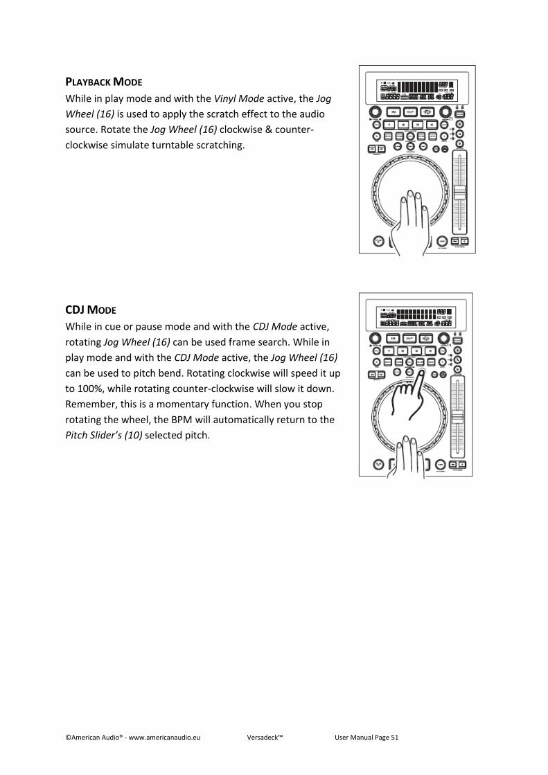
©American Audio® - www.americanaudio.eu Versadeck™ User Manual Page 51
PLAYBACK MODE
While in play mode and with the Vinyl Mode active, the Jog
Wheel (16) is used to apply the scratch effect to the audio
source. Rotate the Jog Wheel (16) clockwise & counter-
clockwise simulate turntable scratching.
CDJ MODE
While in cue or pause mode and with the CDJ Mode active,
rotating Jog Wheel (16) can be used frame search. While in
play mode and with the CDJ Mode active, the Jog Wheel (16)
can be used to pitch bend. Rotating clockwise will speed it up
to 100%, while rotating counter-clockwise will slow it down.
Remember, this is a momentary function. When you stop
rotating the wheel, the BPM will automatically return to the
Pitch Slider’s (10) selected pitch.
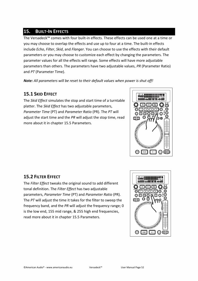
©American Audio® - www.americanaudio.eu Versadeck™ User Manual Page 52
15. BUILT-IN EFFECTS The Versadeck™ comes with four built-in effects. These effects can be used one at a time or
you may choose to overlap the effects and use up to four at a time. The built-in effects
include Echo, Filter, Skid, and Flanger. You can choose to use the effects with their default
parameters or you may choose to customize each effect by changing the parameters. The
parameter values for all the effects will range. Some effects will have more adjustable
parameters than others. The parameters have two adjustable values, PR (Parameter Ratio)
and PT (Parameter Time).
Note: All parameters will be reset to their default values when power is shut off!
15.1 SKID EFFECT The Skid Effect simulates the stop and start time of a turntable
platter. The Skid Effect has two adjustable parameters,
Parameter Time (PT) and Parameter Ratio (PR). The PT will
adjust the start time and the PR will adjust the stop time, read
more about it in chapter 15.5 Parameters.
15.2 FILTER EFFECT The Filter Effect tweaks the original sound to add different
tonal definition. The Filter Effect has two adjustable
parameters, Parameter Time (PT) and Parameter Ratio (PR).
The PT will adjust the time it takes for the filter to sweep the
frequency band, and the PR will adjust the frequency range; 0
is the low end, 155 mid range, & 255 high end frequencies,
read more about it in chapter 15.5 Parameters.
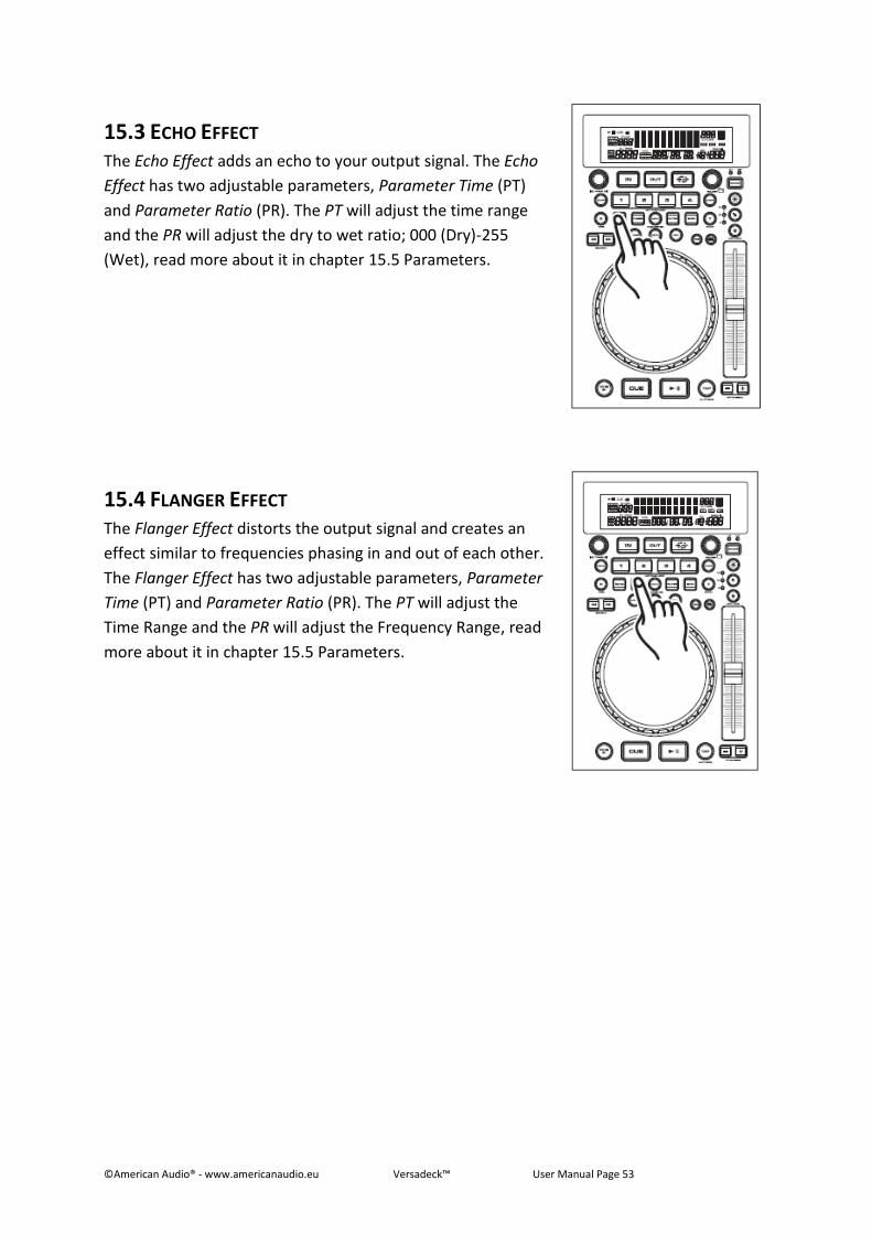
©American Audio® - www.americanaudio.eu Versadeck™ User Manual Page 53
15.3 ECHO EFFECT The Echo Effect adds an echo to your output signal. The Echo
Effect has two adjustable parameters, Parameter Time (PT)
and Parameter Ratio (PR). The PT will adjust the time range
and the PR will adjust the dry to wet ratio; 000 (Dry)-255
(Wet), read more about it in chapter 15.5 Parameters.
15.4 FLANGER EFFECT The Flanger Effect distorts the output signal and creates an
effect similar to frequencies phasing in and out of each other.
The Flanger Effect has two adjustable parameters, Parameter
Time (PT) and Parameter Ratio (PR). The PT will adjust the
Time Range and the PR will adjust the Frequency Range, read
more about it in chapter 15.5 Parameters.
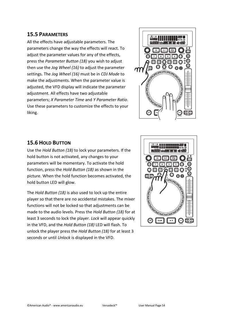
©American Audio® - www.americanaudio.eu Versadeck™ User Manual Page 54
15.5 PARAMETERS All the effects have adjustable parameters. The
parameters change the way the effects will react. To
adjust the parameter values for any of the effects,
press the Parameter Button (18) you wish to adjust
then use the Jog Wheel (16) to adjust the parameter
settings. The Jog Wheel (16) must be in CDJ Mode to
make the adjustments. When the parameter value is
adjusted, the VFD display will indicate the parameter
adjustment. All effects have two adjustable
parameters; X Parameter Time and Y Parameter Ratio.
Use these parameters to customize the effects to your
liking.
15.6 HOLD BUTTON Use the Hold Button (18) to lock your parameters. If the
hold button is not activated, any changes to your
parameters will be momentary. To activate the hold
function, press the Hold Button (18) as shown in the
picture. When the hold function becomes activated, the
hold button LED will glow.
The Hold Button (18) is also used to lock up the entire
player so that there are no accidental mistakes. The mixer
functions will not be locked so that adjustments can be
made to the audio levels. Press the Hold Button (18) for at
least 3 seconds to lock the player. Lock will appear quickly
in the VFD, and the Hold Button (18) LED will flash. To
unlock the player press the Hold Button (18) for at least 3
seconds or until Unlock is displayed in the VFD.
©American Audio® - www.americanaudio.eu Versadeck™ User Manual Page 55
16. PLAYLIST OPERATION 1. Press and hold the Folder Knob (1) for 3 seconds to enter the internal menu. Turn the
knob until Playlist is displayed.
2. Turn the Track Knob (21) to scroll through Normal/Title/Artist/Album/Genre. Press the
Folder Knob (1) to save your desired selection and exit. The database should adjust to
your setting.
EXAMPLE
Artist is selected; all artists will be in alphabetical order.
Pushing and turning the Folder Knob (1) will take you to the next letter; so if you are
going through the C artists, holding and turning the Folder Knob (1) will skip you up to
the D artists.
You can turn the Folder Knob (1), or push the Folder Knob (1) in and turn the Jog Wheel
(16) to jump to the next artist.
You can skip through tracks by turning the Track Knob (21), or by pressing the Track
Knob (21) and turning the Jog Wheel (16) as well.
©American Audio® - www.americanaudio.eu Versadeck™ User Manual Page 56
17. RELAY MODE (FLIP-FLOP™) This feature is a kind of “auto pilot”. When you are using the Versadeck™ system, you can
have one player begin playback when the other ends. You can Relay single tracks, the entire
folder, or a combination of the two.
17.1 RELAY SINGLE TRACKS 1. Set the mixer's crossfader to the center position, and press the Relay Button (34).
2. Set the two players to playback in single mode, Single (72) should be indicated in the
VFD (23).
3. Load your two players with audio discs.
4. After they have both cued, press the Play/Pause Button (13) on one player to begin
playback.
5. After the first player’s single track has ended the second player’s track will immediately
begin playback.
6. FLIP-FLOP™ will continue until you stop it or power is interrupted.
17.2 FLIP-FLOP™ ENTIRE FOLDERS Be sure your players are both in continuous play mode, make sure Single Mode (72) does not
appear in the VFD Displays (23) of both players. Follow all directions for single track Relay
above. When one player’s folder ends the other player will immediately begin playback.
Note: You may combine Relay single and continuously playback modes by selecting either
single or continuous playback on your units.
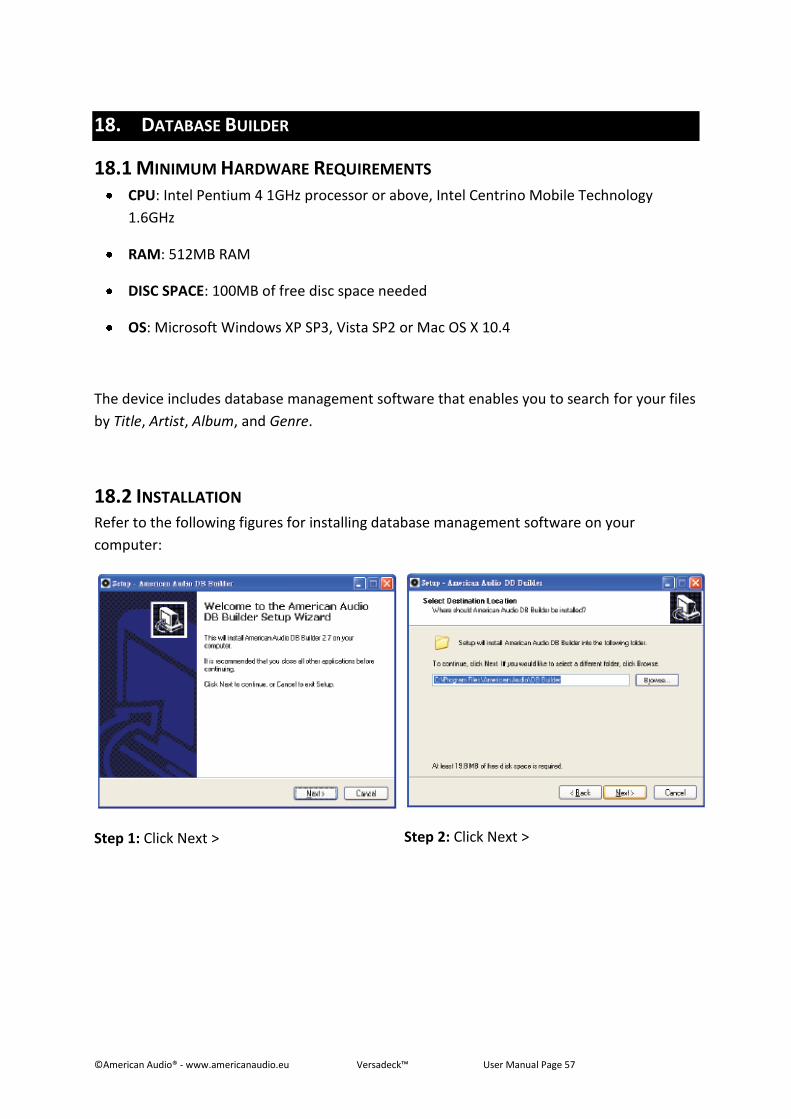
©American Audio® - www.americanaudio.eu Versadeck™ User Manual Page 57
18. DATABASE BUILDER
18.1 MINIMUM HARDWARE REQUIREMENTS CPU: Intel Pentium 4 1GHz processor or above, Intel Centrino Mobile Technology
1.6GHz
RAM: 512MB RAM
DISC SPACE: 100MB of free disc space needed
OS: Microsoft Windows XP SP3, Vista SP2 or Mac OS X 10.4
The device includes database management software that enables you to search for your files
by Title, Artist, Album, and Genre.
18.2 INSTALLATION Refer to the following figures for installing database management software on your
computer:
Step 1: Click Next >
Step 2: Click Next >
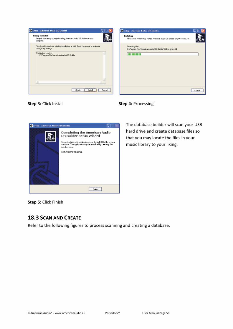
©American Audio® - www.americanaudio.eu Versadeck™ User Manual Page 58
Step 3: Click Install
Step 4: Processing
Step 5: Click Finish
The database builder will scan your USB
hard drive and create database files so
that you may locate the files in your
music library to your liking.
18.3 SCAN AND CREATE Refer to the following figures to process scanning and creating a database.
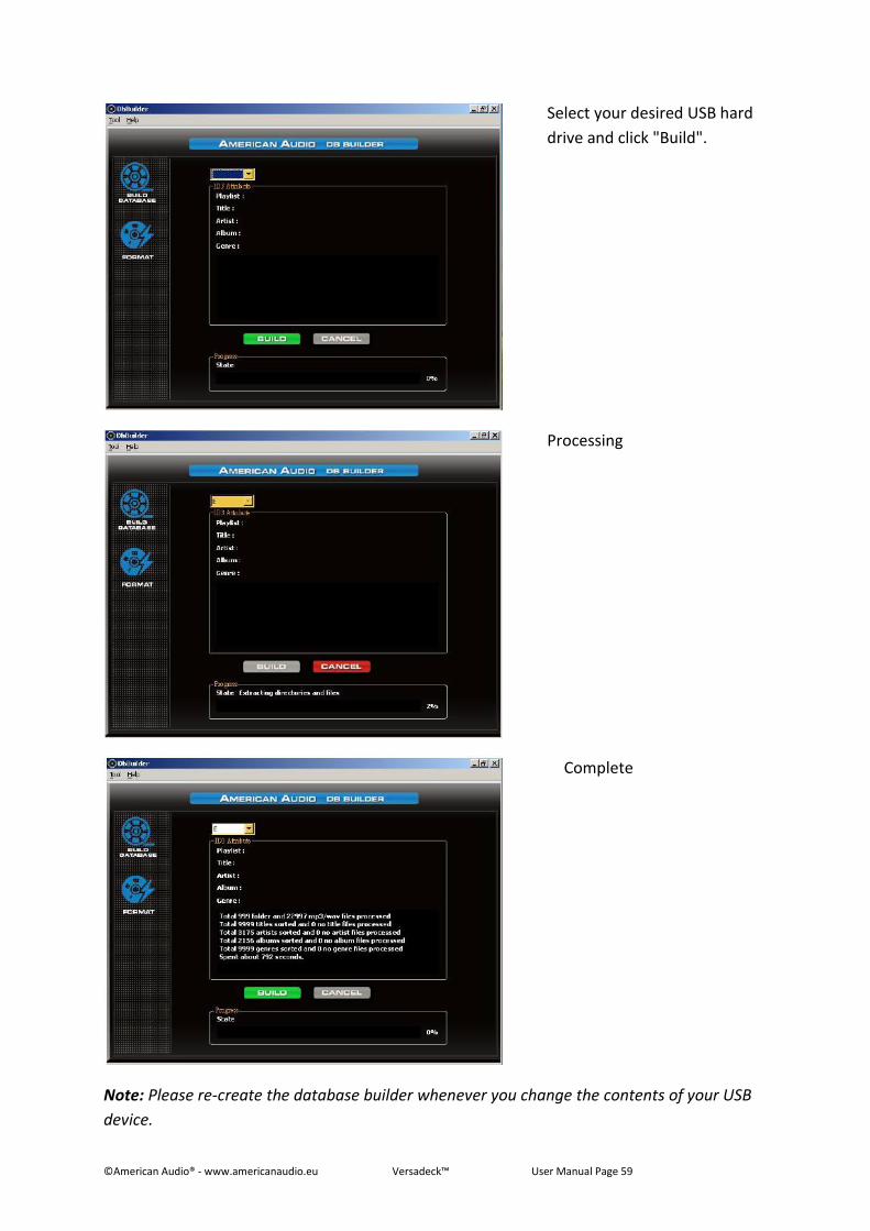
©American Audio® - www.americanaudio.eu Versadeck™ User Manual Page 59
Select your desired USB hard
drive and click "Build".
Processing
Complete
Note: Please re-create the database builder whenever you change the contents of your USB
device.
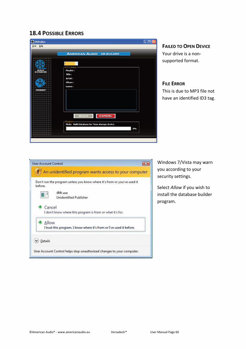
©American Audio® - www.americanaudio.eu Versadeck™ User Manual Page 60
18.4 POSSIBLE ERRORS
FAILED TO OPEN DEVICE
Your drive is a non-
supported format.
FILE ERROR
This is due to MP3 file not
have an identified ID3 tag.
Windows 7/Vista may warn
you according to your
security settings.
Select Allow if you wish to
install the database builder
program.
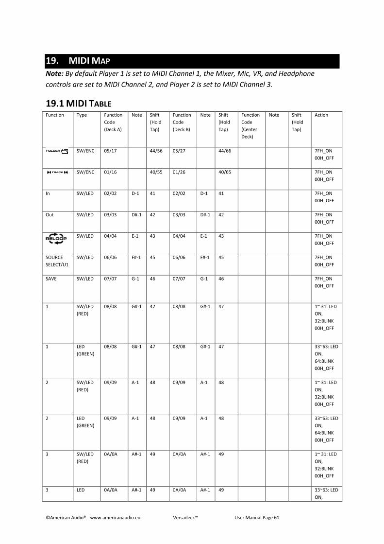
©American Audio® - www.americanaudio.eu Versadeck™ User Manual Page 61
19. MIDI MAP Note: By default Player 1 is set to MIDI Channel 1, the Mixer, Mic, VR, and Headphone
controls are set to MIDI Channel 2, and Player 2 is set to MIDI Channel 3.
19.1 MIDI TABLE Function Type Function
Code
(Deck A)
Note Shift
(Hold
Tap)
Function
Code
(Deck B)
Note Shift
(Hold
Tap)
Function
Code
(Center
Deck)
Note Shift
(Hold
Tap)
Action
SW/ENC 05/17 44/56 05/27 44/66 7FH_ON
00H_OFF
SW/ENC 01/16 40/55 01/26 40/65 7FH_ON
00H_OFF
In SW/LED 02/02 D-1 41 02/02 D-1 41 7FH_ON
00H_OFF
Out SW/LED 03/03 D#-1 42 03/03 D#-1 42 7FH_ON
00H_OFF
SW/LED 04/04 E-1 43 04/04 E-1 43 7FH_ON
00H_OFF
SOURCE
SELECT/U1
SW/LED 06/06 F#-1 45 06/06 F#-1 45 7FH_ON
00H_OFF
SAVE SW/LED 07/07 G-1 46 07/07 G-1
46 7FH_ON
00H_OFF
1 SW/LED
(RED)
08/08 G#-1 47 08/08 G#-1 47 1~ 31: LED
ON,
32:BLINK
00H_OFF
1 LED
(GREEN)
08/08 G#-1 47 08/08 G#-1 47 33~63: LED
ON,
64:BLINK
00H_OFF
2 SW/LED
(RED)
09/09 A-1 48 09/09 A-1 48 1~ 31: LED
ON,
32:BLINK
00H_OFF
2 LED
(GREEN)
09/09 A-1 48 09/09 A-1 48 33~63: LED
ON,
64:BLINK
00H_OFF
3 SW/LED
(RED)
0A/0A A#-1 49 0A/0A A#-1 49 1~ 31: LED
ON,
32:BLINK
00H_OFF
3 LED 0A/0A A#-1 49 0A/0A A#-1 49 33~63: LED
ON,
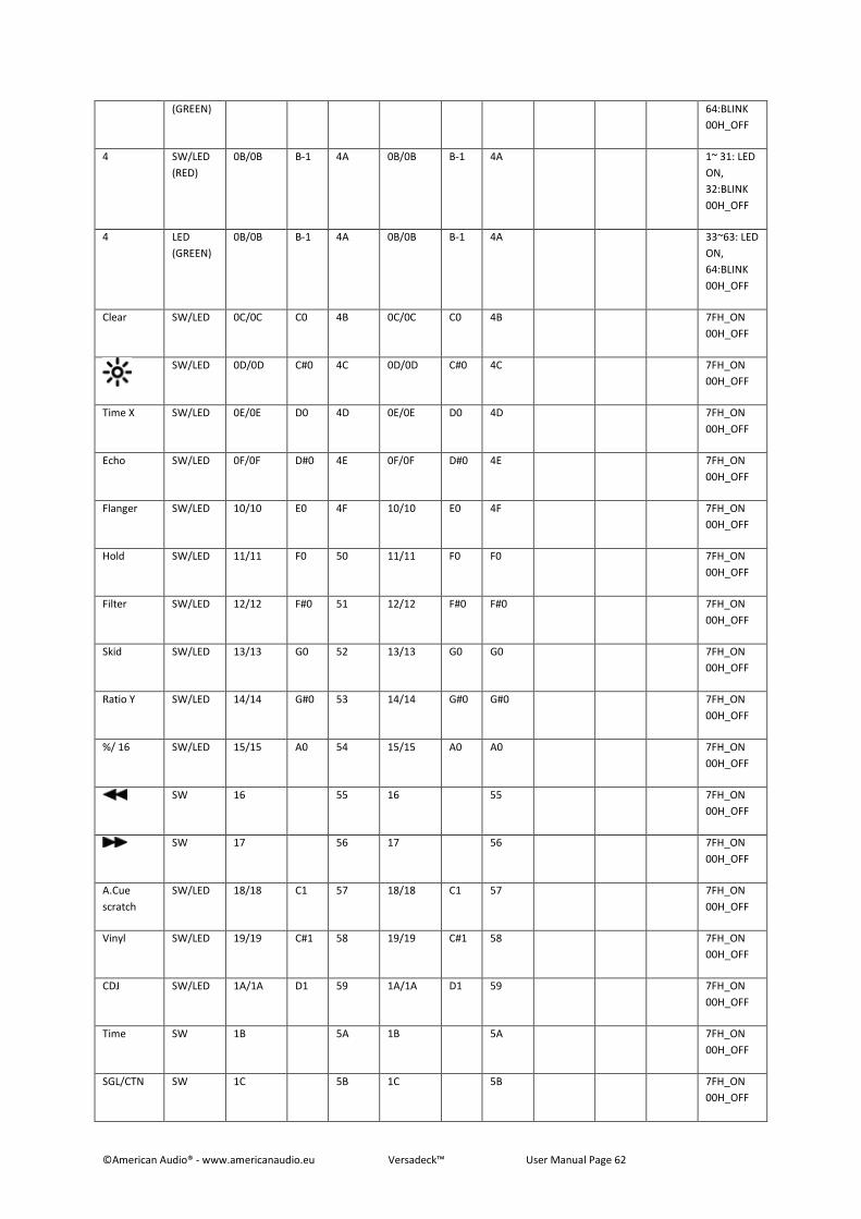
©American Audio® - www.americanaudio.eu Versadeck™ User Manual Page 62
(GREEN) 64:BLINK
00H_OFF
4 SW/LED
(RED)
0B/0B B-1 4A 0B/0B B-1 4A 1~ 31: LED
ON,
32:BLINK
00H_OFF
4 LED
(GREEN)
0B/0B B-1 4A 0B/0B B-1 4A 33~63: LED
ON,
64:BLINK
00H_OFF
Clear SW/LED 0C/0C C0 4B 0C/0C C0 4B 7FH_ON
00H_OFF
SW/LED 0D/0D C#0 4C 0D/0D C#0 4C 7FH_ON
00H_OFF
Time X SW/LED 0E/0E D0 4D 0E/0E D0 4D 7FH_ON
00H_OFF
Echo SW/LED 0F/0F D#0 4E 0F/0F D#0 4E 7FH_ON
00H_OFF
Flanger SW/LED 10/10 E0 4F 10/10 E0 4F 7FH_ON
00H_OFF
Hold SW/LED 11/11 F0 50 11/11 F0 F0 7FH_ON
00H_OFF
Filter SW/LED 12/12 F#0 51 12/12 F#0 F#0 7FH_ON
00H_OFF
Skid SW/LED 13/13 G0 52 13/13 G0 G0 7FH_ON
00H_OFF
Ratio Y SW/LED 14/14 G#0 53 14/14 G#0 G#0 7FH_ON
00H_OFF
%/ 16 SW/LED 15/15 A0 54 15/15 A0 A0 7FH_ON
00H_OFF
SW 16 55 16 55 7FH_ON
00H_OFF
SW 17 56 17 56 7FH_ON
00H_OFF
A.Cue
scratch
SW/LED 18/18 C1 57 18/18 C1 57 7FH_ON
00H_OFF
Vinyl SW/LED 19/19 C#1 58 19/19 C#1 58 7FH_ON
00H_OFF
CDJ SW/LED 1A/1A D1 59 1A/1A D1 59 7FH_ON
00H_OFF
Time SW 1B 5A 1B 5A 7FH_ON
00H_OFF
SGL/CTN SW 1C 5B 1C 5B 7FH_ON
00H_OFF
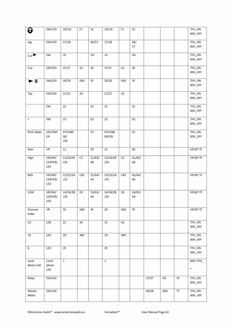
©American Audio® - www.americanaudio.eu Versadeck™ User Manual Page 63
SW/LED 1D/1D F1 5C 1D/1D F1 5C 7FH_ON
00H_OFF
Jog SW/LED 27/18 66/57 27/28 66/
57
7FH_ON
00H_OFF
Cue SW 1E 5D 1E 5D 7FH_ON
00H_OFF
Cue SW/LED 1F/1F G1 5E 1F/1F G1 5E 7FH_ON
00H_OFF
SW/LED 20/20 G#1 5F 20/20 G#1 5F 7FH_ON
00H_OFF
Tap SW/LED 21/21 A1 21/21 A1 7FH_ON
00H_OFF
- SW 22 61 22 61 7FH_ON
00H_OFF
+ SW 23 62 23 62 7FH_ON
00H_OFF
Pitch Slider VR/CENT
ER
PITCHBE
ND
/28
67 PITCHBE
ND/28
67 7FH_ON
00H_OFF
Gain VR 11 50 21 60 VR:00~7F
High VR/SW/
CENTER/
LED
12/24/29
/24
C2 51/63/
68
22/24/29
/24
C2 61/63/
68
VR:00~7F
MID VR/SW/
CENTER/
LED
13/25/2A
/25
C#2 52/64/
69
23/25/2A
/25
C#2 62/64/
69
VR:00~7F
LOW VR/SW/
CENTER/
LED
14/26/2B
/26
D2 53/65/
6A
24/26/2B
/26
D2 63/65/
6A
VR:00~7F
Channel
Fader
VR 10 G#2 4F 20 G#2 5F VR:00~7F
U2 LED 2C A2 2C A2 7FH_ON
00H_OFF
10 LED 2D A#2 2D A#2 7FH_ON
00H_OFF
6 LED 2E 2E 7FH_ON
00H_OFF
Level
Meter LED
Level
Meter
LED
1 1 00H~7FH_
*
Relay SW/LED 37/37 G3 76 7FH_ON
00H_OFF
Master
Meter
SW/LED 38/38 G#3 77 7FH_ON
00H_OFF
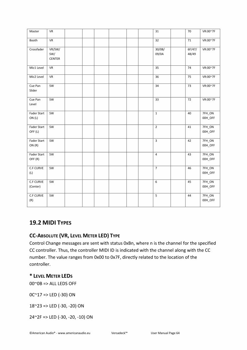
©American Audio® - www.americanaudio.eu Versadeck™ User Manual Page 64
Master VR 31 70 VR:00~7F
Booth VR 32 71 VR:00~7F
Crossfader VR/SW/
SW/
CENTER
30/08/
09/0A
6F/47/
48/49
VR:00~7F
Mic1 Level VR 35 74 VR:00~7F
Mic2 Level VR 36 75 VR:00~7F
Cue Pan
Slider
SW 34 73 VR:00~7F
Cue Pan
Level
SW 33 72 VR:00~7F
Fader Start
ON (L)
SW 1 40 7FH_ON
00H_OFF
Fader Start
OFF (L)
SW 2 41 7FH_ON
00H_OFF
Fader Start
ON (R)
SW 3 42 7FH_ON
00H_OFF
Fader Start
OFF (R)
SW 4 43 7FH_ON
00H_OFF
C.F CURVE
(L)
SW 7 46 7FH_ON
00H_OFF
C.F CURVE
(Center)
SW 6 45 7FH_ON
00H_OFF
C.F CURVE
(R)
SW 5 44 7FH_ON
00H_OFF
19.2 MIDI TYPES
CC-ABSOLUTE (VR, LEVEL METER LED) TYPE
Control Change messages are sent with status 0xBn, where n is the channel for the specified
CC controller. Thus, the controller MIDI ID is indicated with the channel along with the CC
number. The value ranges from 0x00 to 0x7F, directly related to the location of the
controller.
* LEVEL METER LEDS
00~0B => ALL LEDS OFF
0C~17 => LED (-30) ON
18~23 => LED (-30, -20) ON
24~2F => LED (-30, -20, -10) ON
©American Audio® - www.americanaudio.eu Versadeck™ User Manual Page 65
30~3B => LED (-30, -20, -10, -7) ON
3C~47 => LED (-30, -20, -10, -7, -4) ON
48~53 => LED (-30, -20, -10, -7, -4, -2) ON
54~5F => LED (-30, -20, -10, -7, -4, -2, 0) ON
60~6B => LED (-30, -20, -10, -7, -4, -2, 0, +2) ON
6C~77 => LED (-30, -20, -10, -7, -4, -2, 0, +2, +4) ON
78~7F => ALL LEDS ON (-30, -20, -10, -7, -4, -2, 0, +2, +4, +7)
CC-RELATIVE (ENC) TYPE
Control Change messages are sent with status 0xBn, where n is the channel for the specified
CC controller. Thus, the controller MIDI ID is indicated with the channel along with the CC
number. The value ranges from 0x40 to indicate the change in the controller. This is an offset
to 0x40 “one’s complement” notation. A message with data 0x43 indicates a positive change
of 3. A messages with data 0x31 indicates a negative change of 15.
SWITCH ON/OFF (SW, CENTER TYPE)
These messages are used for switches. Control Change messages are sent with status 0x9n,
Switch On and Off values are 0x7F and 0x00, where n is the channel.
LED ON/OFF (LED TYPE)
These messages are used for LEDs. Control Change messages are sent with status 0x9n, LED
On and Off values are 0x7F and 0x00, where n is the channel.*
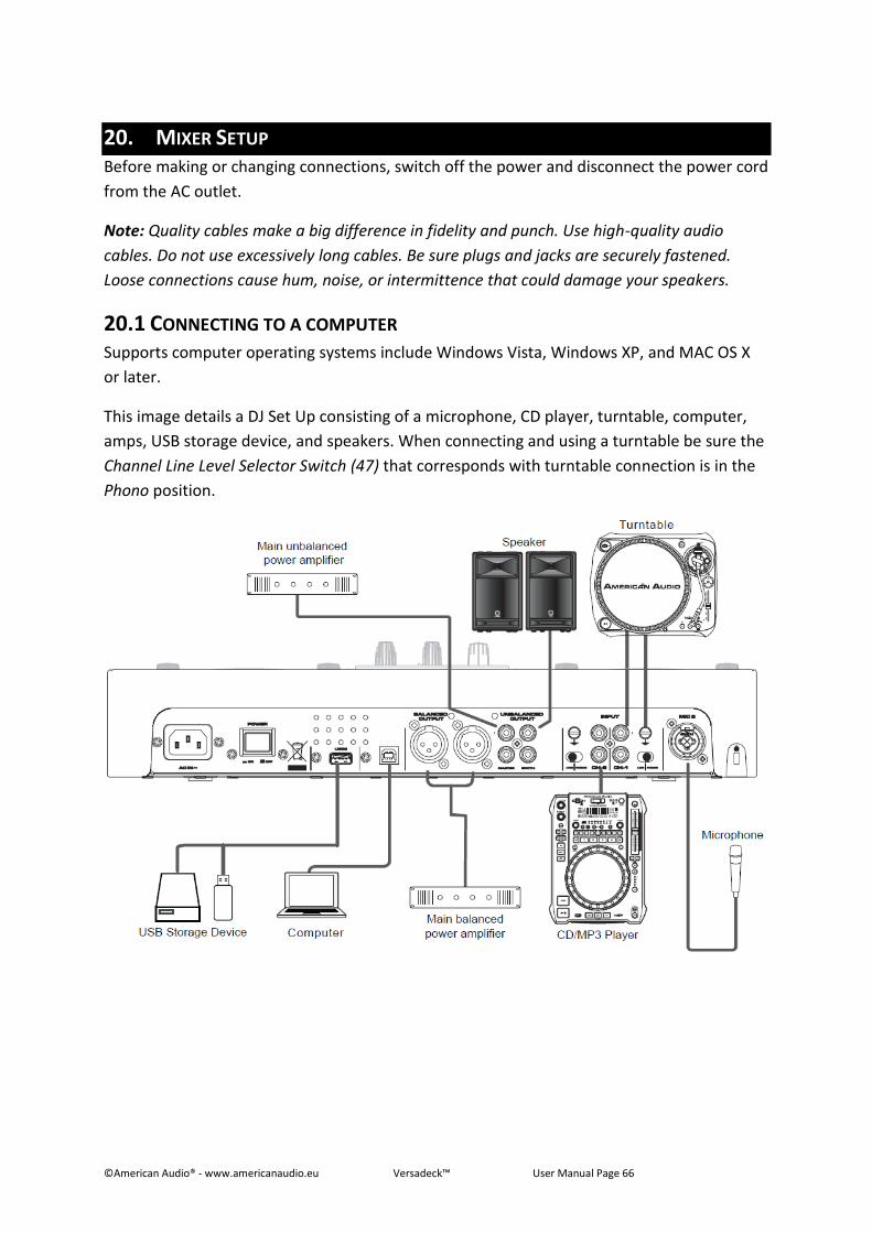
©American Audio® - www.americanaudio.eu Versadeck™ User Manual Page 66
20. MIXER SETUP Before making or changing connections, switch off the power and disconnect the power cord
from the AC outlet.
Note: Quality cables make a big difference in fidelity and punch. Use high-quality audio
cables. Do not use excessively long cables. Be sure plugs and jacks are securely fastened.
Loose connections cause hum, noise, or intermittence that could damage your speakers.
20.1 CONNECTING TO A COMPUTER Supports computer operating systems include Windows Vista, Windows XP, and MAC OS X
or later.
This image details a DJ Set Up consisting of a microphone, CD player, turntable, computer,
amps, USB storage device, and speakers. When connecting and using a turntable be sure the
Channel Line Level Selector Switch (47) that corresponds with turntable connection is in the
Phono position.
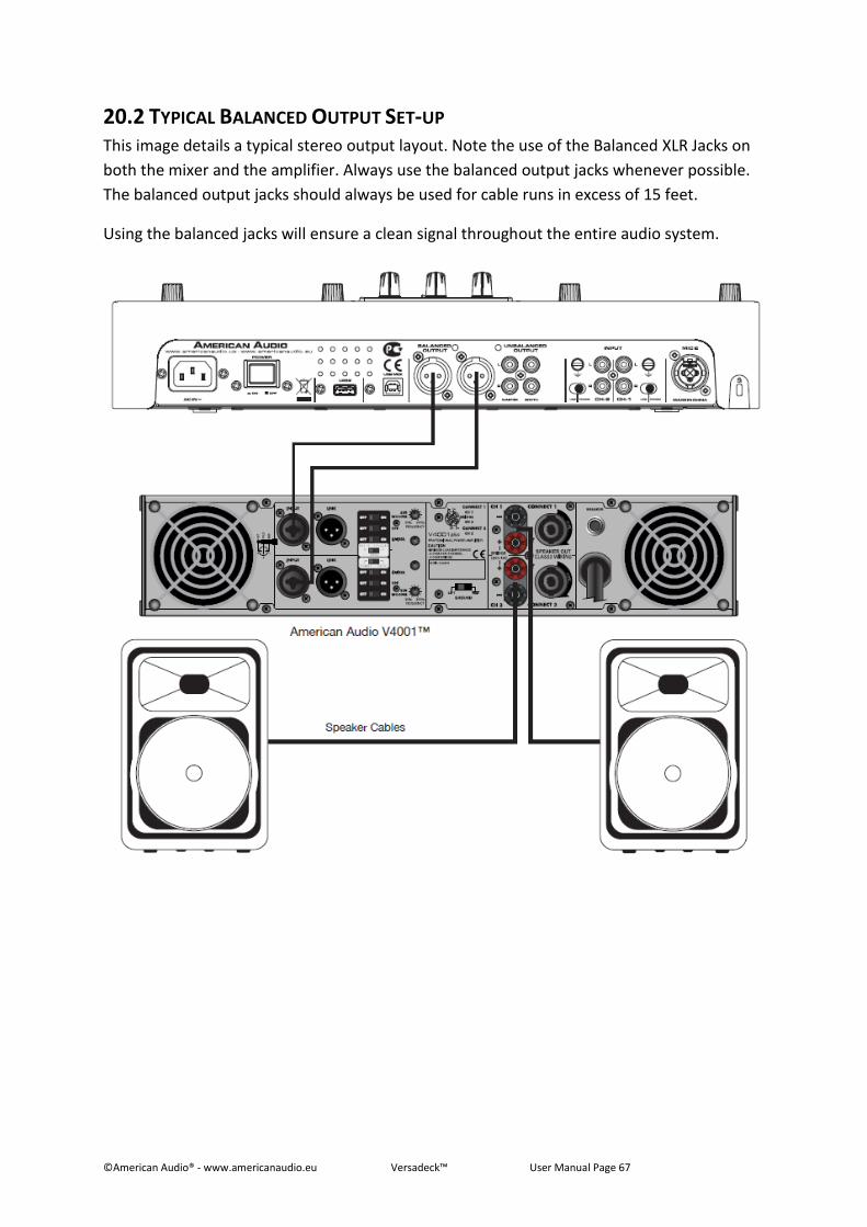
©American Audio® - www.americanaudio.eu Versadeck™ User Manual Page 67
20.2 TYPICAL BALANCED OUTPUT SET-UP This image details a typical stereo output layout. Note the use of the Balanced XLR Jacks on
both the mixer and the amplifier. Always use the balanced output jacks whenever possible.
The balanced output jacks should always be used for cable runs in excess of 15 feet.
Using the balanced jacks will ensure a clean signal throughout the entire audio system.
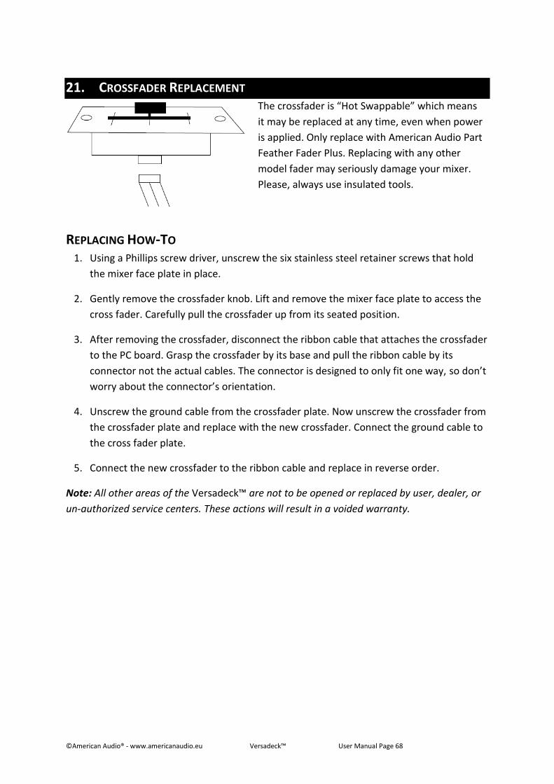
©American Audio® - www.americanaudio.eu Versadeck™ User Manual Page 68
21. CROSSFADER REPLACEMENT
The crossfader is “Hot Swappable” which means
it may be replaced at any time, even when power
is applied. Only replace with American Audio Part
Feather Fader Plus. Replacing with any other
model fader may seriously damage your mixer.
Please, always use insulated tools.
REPLACING HOW-TO 1. Using a Phillips screw driver, unscrew the six stainless steel retainer screws that hold
the mixer face plate in place.
2. Gently remove the crossfader knob. Lift and remove the mixer face plate to access the
cross fader. Carefully pull the crossfader up from its seated position.
3. After removing the crossfader, disconnect the ribbon cable that attaches the crossfader
to the PC board. Grasp the crossfader by its base and pull the ribbon cable by its
connector not the actual cables. The connector is designed to only fit one way, so don’t
worry about the connector’s orientation.
4. Unscrew the ground cable from the crossfader plate. Now unscrew the crossfader from
the crossfader plate and replace with the new crossfader. Connect the ground cable to
the cross fader plate.
5. Connect the new crossfader to the ribbon cable and replace in reverse order.
Note: All other areas of the Versadeck™ are not to be opened or replaced by user, dealer, or
un-authorized service centers. These actions will result in a voided warranty.
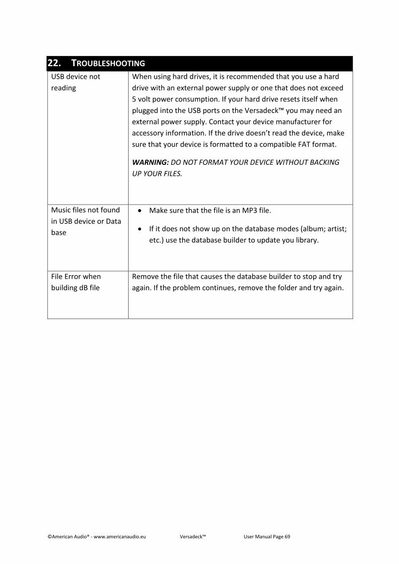
©American Audio® - www.americanaudio.eu Versadeck™ User Manual Page 69
22. TROUBLESHOOTING USB device not
reading
When using hard drives, it is recommended that you use a hard
drive with an external power supply or one that does not exceed
5 volt power consumption. If your hard drive resets itself when
plugged into the USB ports on the Versadeck™ you may need an
external power supply. Contact your device manufacturer for
accessory information. If the drive doesn’t read the device, make
sure that your device is formatted to a compatible FAT format.
WARNING: DO NOT FORMAT YOUR DEVICE WITHOUT BACKING
UP YOUR FILES.
Music files not found
in USB device or Data
base
Make sure that the file is an MP3 file.
If it does not show up on the database modes (album; artist;
etc.) use the database builder to update you library.
File Error when
building dB file
Remove the file that causes the database builder to stop and try
again. If the problem continues, remove the folder and try again.

©American Audio® - www.americanaudio.eu Versadeck™ User Manual Page 70
23. ROHS – A CONTRIBUTION TO THE CONSERVATION OF ENVIRONMENT The European Union has adopted a directive on the restriction/prohibition of the use of
hazardous substances. This directive, referred to as ROHS, is a frequently discussed topic in
the electronic industry.
It restricts, among other things, six materials: Lead (Pb), Mercury (Hg), Hexavalent Chromium
(CR VI), Cadmium (Cd), Polybrimated Biphenyls as flame retardant (PBB), Polybrominated
Diphenyl, also a flame retardant (PBDE). The directive applies to nearly all electronic and
electrical devices whose mode of operation involves electric or electromagnetic fields – in
short: each kind of electronics we have around us in our households or at work.
As manufacturers of products of the brands of AMERICAN AUDIO®, AMERICAN DJ®, ELATION
Professional and ACCLAIM Lighting, we are obligated to comply with the ROHS directive.
Therefore, as early as two years prior to the directive coming into force, we started our
search for alternative environmentally friendly materials and manufacturing processes.
Well before the ROHS directive took effect, all of our products were manufactured meeting
the standards of the European Union. With regular audits and material tests we can still
assure that the components we use are always ROHS-compliant and that the manufacturing
process, as far as the state of technology allows, is environmentally friendly.
The ROHS directive is an important step to the protection of our environment. We, as
manufactures, feel obligated to make our contribution in this respect.

©American Audio® - www.americanaudio.eu Versadeck™ User Manual Page 71
24. WEEE – WASTE OF ELECTRICAL AND ELECTRONIC EQUIPMENT Every year thousands of tons of electronic components, which are harmful to the
environment, end up at the waste disposals around the world. To ensure the best possible
disposal or recovery of electronic components, the European Union has adopted the WEEE
directive.
The WEEE-system (Waste of Electrical and Electronic Equipment) can be compared with the
system of the “Green Spot”, which has been in use for several years. The manufactures have
to make their contribution to the utilization of waste at the time they release the product.
Money resources obtained by doing so will be applied to develop a common system of waste
management. Thereby we can ensure professional and environmentally friendly scraping
and recycling program.
As manufactures, we are part of the German system of EAR and we make our contribution
towards it.
(Registration in Germany: DE41027552)
That means that products of AMERICAN DJ® and AMERICAN AUDIO® can be left in the
collection points free of charge and they will be used in the recycling program. Products of
ELATION Professional, which are used only by professionals, shall be handled by us. Please
send Elation products directly to us at the end of their lifetime so that we can professionally
dispose of them.
Like the above ROHS, the WEEE directive is an important contribution to the environment
protection and we are glad to help to clean the environment with this disposal system.
We are happy to answer any of your inquiries and welcome your suggestions at:
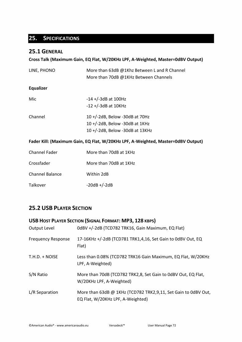
©American Audio® - www.americanaudio.eu Versadeck™ User Manual Page 72
25. SPECIFICATIONS
25.1 GENERAL Cross Talk (Maximum Gain, EQ Flat, W/20KHz LPF, A-Weighted, Master=0dBV Output)
LINE, PHONO More than 63dB @1Khz Between L and R Channel
More than 70dB @1KHz Between Channels
Equalizer
Mic -14 +/-3dB at 100Hz
-12 +/-3dB at 10KHz
Channel 10 +/-2dB, Below -30dB at 70Hz
10 +/-2dB, Below -30dB at 1KHz
10 +/-2dB, Below -30dB at 13KHz
Fader Kill: (Maximum Gain, EQ Flat, W/20KHz LPF, A-Weighted, Master=0dBV Output)
Channel Fader More than 70dB at 1KHz
Crossfader More than 70dB at 1KHz
Channel Balance Within 2dB
Talkover -20dB +/-2dB
25.2 USB PLAYER SECTION
USB HOST PLAYER SECTION (SIGNAL FORMAT: MP3, 128 KBPS)
Output Level 0dBV +/-2dB (TCD782 TRK16, Gain Maximum, EQ Flat)
Frequency Response 17-16KHz +/-2dB (TCD781 TRK1,4,16, Set Gain to 0dBV Out, EQ
Flat)
T.H.D. + NOISE Less than 0.08% (TCD782 TRK16 Gain Maximum, EQ Flat, W/20KHz
LPF, A-Weighted)
S/N Ratio More than 70dB (TCD782 TRK2,8, Set Gain to 0dBV Out, EQ Flat,
W/20KHz LPF, A-Weighted)
L/R Separation More than 63dB @ 1KHz (TCD782 TRK2,9,11, Set Gain to 0dBV Out,
EQ Flat, W/20KHz LPF, A-Weighted)
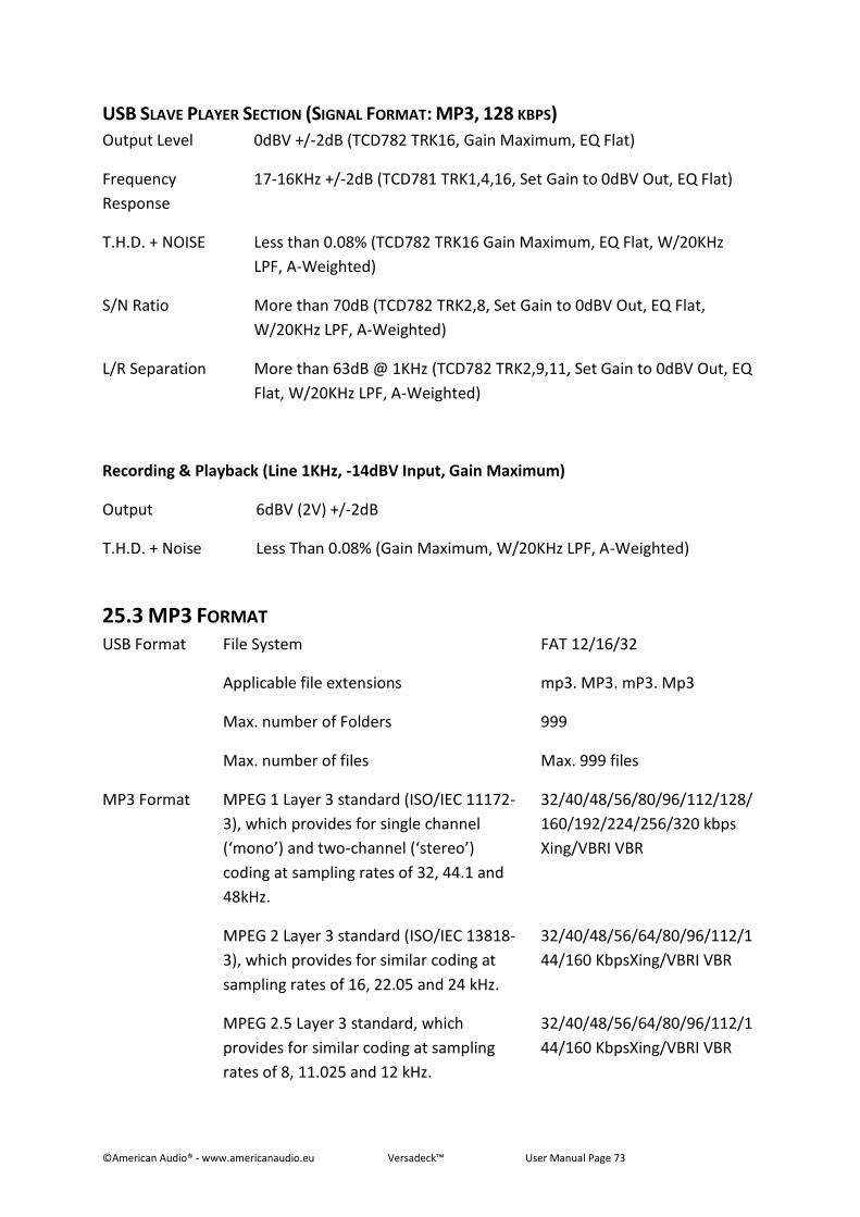
©American Audio® - www.americanaudio.eu Versadeck™ User Manual Page 73
USB SLAVE PLAYER SECTION (SIGNAL FORMAT: MP3, 128 KBPS)
Output Level 0dBV +/-2dB (TCD782 TRK16, Gain Maximum, EQ Flat)
Frequency
Response
17-16KHz +/-2dB (TCD781 TRK1,4,16, Set Gain to 0dBV Out, EQ Flat)
T.H.D. + NOISE Less than 0.08% (TCD782 TRK16 Gain Maximum, EQ Flat, W/20KHz
LPF, A-Weighted)
S/N Ratio More than 70dB (TCD782 TRK2,8, Set Gain to 0dBV Out, EQ Flat,
W/20KHz LPF, A-Weighted)
L/R Separation More than 63dB @ 1KHz (TCD782 TRK2,9,11, Set Gain to 0dBV Out, EQ
Flat, W/20KHz LPF, A-Weighted)
Recording & Playback (Line 1KHz, -14dBV Input, Gain Maximum)
Output 6dBV (2V) +/-2dB
T.H.D. + Noise Less Than 0.08% (Gain Maximum, W/20KHz LPF, A-Weighted)
25.3 MP3 FORMAT USB Format File System FAT 12/16/32
Applicable file extensions mp3. MP3. mP3. Mp3
Max. number of Folders 999
Max. number of files Max. 999 files
MP3 Format MPEG 1 Layer 3 standard (ISO/IEC 11172-
3), which provides for single channel
(‘mono’) and two-channel (‘stereo’)
coding at sampling rates of 32, 44.1 and
48kHz.
32/40/48/56/80/96/112/128/
160/192/224/256/320 kbps
Xing/VBRI VBR
MPEG 2 Layer 3 standard (ISO/IEC 13818-
3), which provides for similar coding at
sampling rates of 16, 22.05 and 24 kHz.
32/40/48/56/64/80/96/112/1
44/160 KbpsXing/VBRI VBR
MPEG 2.5 Layer 3 standard, which
provides for similar coding at sampling
rates of 8, 11.025 and 12 kHz.
32/40/48/56/64/80/96/112/1
44/160 KbpsXing/VBRI VBR

©American Audio® - www.americanaudio.eu Versadeck™ User Manual Page 74
Note: Specifications and improvements in the design of this unit and this manual are subject
to change without any prior written notice.

©American Audio® - www.americanaudio.eu Versadeck™ User Manual Page 75
Follow us on:
facebook.com/americandj
twitter.com/americandj
youtube.com/adjlighting
©American Audio® - www.americanaudio.eu Versadeck™ User Manual Page 76
©American Audio® World Headquarters
6122 S. Eastern Ave. Los Angeles, CA 90040 USA
Tel: 323-582-3322 Fax: 323-582-3311
Web: www.AmericanAudio.us
E-mail: [email protected]
American DJ Europe
Junostraat 2
6468 EW Kerkrade
Netherlands
www.americandj.eu
Tel: +31 45 546 85 00
Fax: +31 45 546 85 99