extrusion of 1/2- and 3/8-inch-diameter, thin-wall ... · pdf filetech library kafb, nm nasa...
TRANSCRIPT

N A S A TECHNICAL NOTE
1 I . ,
N A S A TN c . I --
EXTRUSION OF 1/2- AND 3/8-INCH-DIAMETER, THIN-WALL TUNGSTEN T U B I N G USING THE FLOATING-MANDREL TECHNIQUE
by Charles P. Blankenship and Charles A. Gyorgak i /
Lewis Reseurch Center Cleveland, Ohio
N A T I O N A L AERONAUTICS A N D S P A C E A D M I N I S T R A T I O N WASHINGTON, D. C . DECEMBER 1 9 6 6
i
https://ntrs.nasa.gov/search.jsp?R=19670003844 2018-05-03T20:07:26+00:00Z

TECH LIBRARY KAFB, NM
NASA T N D-3772
EXTRUSION O F 1/2- AND 3/8-INCH-DIAMETER, THIN-WALL TUNGSTEN
TUBING USING THE FLOATING-MANDREL TECHNIQUE
By C h a r l e s P. Blankenship and C h a r l e s A . Gyorgak
Lewis R e s e a r c h Cen te r Cleveland, Ohio
N A T I O N A L AERONAUTICS AND SPACE ADMINISTRATION
For sale by the Clearinghouse for Federal Scientific and Technicol Information Springfield, Virginia 22151 - Price $1.00

EXTRUSION OF 1/2- AND 3/8-INCH-DIAMETER, THIN-WALL TUNGSTEN
TUBING USING THE FLOATING-MANDREL TECHNIQUE
by Charles P. Blankenship and Charles A. Gyorgak
Lewis Research Center
SUMMARY
Fabrication of small-diameter, thin-wall tungsten tubing by hot extrusion over a floating mandrel was investigated. Variables studied included extrusion temperature, initial density of the tungsten, and composition of the canning material. Successful ex- trusion of 1/2-inch-diameter tubing over 0.4-inch-diameter mandrels was accomplished at temperatures ranging from 3000' to 4000' F. Tubing of 3/8-inch diameter was ex- truded successfully over 0.3-inch-diameter mandrels at 4000' F. Nominal wall thick- nesses were 0.020 inch, and the maximum usable length was 5 feet.
Within the temperature range investigated, 3000' to 4000' F, tubing extruded from tungsten cylinders having a density near 80 percent of theoretical or greater was fully dense. At 4000' F, fully dense tubing was extruded from approximately 68-percent-dense cylinders. For the best 3/8- and 1/2-inch-diameter tubing, wall thicknesses were within *O. 001 and *O. 002 inch, respectively, and the diameters were within -+O. 005 inch.
At 3500' F, the tensile strength of the extruded tubing, 8300 to 9600 pounds per square inch, was comparable to that of wrought sintered tungsten. Tubing internally pressurized at 3500' F failed at an average tangential s t ress ranging from 9500 to nearly 11 000 pounds per square inch.
INTRO DU CTlON
Requirements in advanced space power systems for refractory- metal tubing compo- nents have resulted in several studies to develop applicable tube fabrication processes, particularly for small-diameter, thin-wall tubing. Adaptation of conventional tube pro- cessing techniques (extrusion of tube shells and subsequent tube reducing and drawing) has proved satisfactory for the more ductile refractory metals, columbium and tantalum, as well as for some of their alloys. The high strength and limited ductility of tungsten have
I

precluded the use of conventional methods. One of the more promising experimental methods of fabricating wrought tungsten
tubing is the "filled-billet" extrusion process (ref. 1). In this procedure, tungsten cyl- inders containing a molybdenum core (and canned in molybdenum) are reduced to tubing by hot extrusion. If necessary, the product can be recanned and reextruded to obtain the tubing size desired. Various sizes have been produced, including 3/8-inch-diameter tubing having a 0.010-inch wall thickness. An axial graphite core has aided in the re- moval of the internal filler material, and a steel can used in conjunction with the molyb- denum has permitted extrusion at a relatively low temperature (2200' F). Also, tungsten- alloy tubing has been fabricated using the "filled-billettt process (ref. 1). After removal of the canning material, warm drawing and special swaging techniques have been utilized to reduce and size the extruded tubing.
and feasibility was indicated for extrusion of relatively large diameter (0.8 in. ), thin- wall tungsten tubing (ref. 1). Because of the higher mandrel s t resses resulting from less load supporting area, mandrel extrusion of small-diameter, thin-wall tubing has received little attention. In addition, the high temperatures required to extrude refractory-metal tubing have been a factor adverse to the use of small-diameter mandrels. However, man- drel extrusion of tubing appears to offer certain advantages over the "filled-billet" pro- cess. Primarily, the number of processing steps would be reduced, and longer lengths of tubing might be more practical from mandrel extrusions (because of the difficulty in re- moving -the core from long lengths of tubing extruded by the tlfilled-billet" process).
The purpose of this investigation was to determine the feasibility of extruding small- diameter, thin-wall tungsten tubing using the floating-mandrel technique. Both 1/2- and 3/8-inch-diameter tubing with a nominal wall thickness of 0.020 inch were selected for study. Billet canning procedures were utilized to lower the effective reduction required in the direct extrusion of thin-wall tubing. Extrusion billet components were prepared by conventional powder-metallurgy methods, and the reduction during extrusion was main- tained at 17 to 1 for both sizes of tubing. Variables studied included extrusion tempera- ture, initial density of the tungsten, and composition of the canning material. Extruded tubing was examined for dimensional variations, surface finish, density, hardness, and microstructure. Mechanical properties were determined at 3500' F under tensile and biaxial s t ress conditions.
The floating-mandrel technique has been used to extrude refractory-metal tube blanks,
MATERIALS, APPARATUS, AND PROCEDURE
Extrus ion Bi l le t Design a n d
Tubing billet design and configuration a re shown
2
Preparat ion
schematically in figure 1. The com-

Tantalum pins (diam., 1/8) ,A-
,-Tungsten cyl inder (see table I for
Figure 1. - Schematic of bil let assembly for ex t ru - sion of tungsten tubing. (Dimensions are in inches. 1
ponents of the 2-inch-nominal-diameter billets were fabricated by conventional powder- metallurgy tech- niques, and both molybdenum and molybdenum - 25- percent-tungsten alloy canning materials were used. In addition to lowering the effective reduction required to extrude thin-wall tubing, the canning material was expected to absorb any minor surface irregularities associated with the extrusion process. Densities of the canning materials ranged from 90 to 95 percent of theoretical as determined by mercury displacement. All billet components were dry machined to size, and a hole was provided through the center of the billet core for mandrel insertion. The billet can and core were held together by fusion of tantalum pins using the gas tungsten-arc process. The pins were located 120' apart along the can-core interface (fig. 1).
To maintain a constant reduction ratio of 17 to 1, tungsten cylinders of different sizes were prepared for
extruding the 1/2- and 3/8-inch-diameter tubing. Cylinder dimensions were calculated assuming fully dense billet components and are listed in table I. The densities of the tungsten cylinders were selected to range from approximately 65 to 95 percent of theo- retical. Cylinders W2- 1 to W2- 5 and W3- 1 to W3-5 (table I) were prepared by conven- tional powder- metallurgy techniques of dry blending, hydrostatic pressing, and sintering. Tungsten powder having an average particle size of 4.5 microns was used in preparing the cylinders, and a hydrostatic pressure of 50 000 pounds per square inch was used for con- solidation. Sintering was accomplished in a hydrogen atmosphere according to the tem- perature and time schedule given in table I. Cylinders W2-6 to W2-9 were procured from a commercial vendor, and the processing procedure was not disclosed. Densities were from 95 to 96 percent of theoretical.
Extrusion Tooling and Procedure
The billets were extruded in a 1020-ton vertical extrusion press equipped with nominal 2-inch-diameter tooling. Tooling alinement was maintained within 0.003 inch. Zirconia- coated extrusion dies having an entrance angle of 90' were used. The die orifices were 0.695 and 0.530 inch for the 1/2- and 3/8-inch-diameter tubing, respectively. Press operation, tooling design, and accessories for extrusion at the relatively high tempera- tures employed herein are described in reference 2.
3

TABLE I. - PROCESSING SCHEDULE AND FINAL DIMENSIONS OF TUNGSTEN
Zylinder
w2-1
w2-2
W2-3 W2-4 W2-5
W2-6
W 2 -7 W2-8 W2-9
W3-1
W3-2 w3-3 w3-4 w3- 5
~~
Final :nominal) tubing
liameter , in.
1/2
3/8
CYLINDERS FOR EXTRUSION OF TUBING
Sintering schedule
Temper- ature,
O F
3000
2 000
1 ~
(b)
1 . .
2 500
I
rime, hr
1
~
1 4
I I
I
~- - ~
(b)
1
Diameter, in.
Outside
+O. 005
-0.000
+O. 005
-0.000
1.300
. . .
1.300
I I +O. 005
-0.000 I. 300
+o. 000 -0.005
1.120
I
Inside
+o. 000
-0.005
+o. 000 -0.005
1.000
1.000
1
I +o. 000 -0.005
1.000
+o. 000 -0.005
3.775
I
Length, in.
4. (k0.05
4. OiO. 05
1
I 4. (k0.05
3.3*0.05
4.0 3.4 3.8 3.9
Density, percent
theoretical
(a)
79 to 80
64 to 65
1
1 95 to 96
67 to 68
I aDetermined by mercury displacement. bObtained from commercial vendor; processing details not disclosed.
,-Oiam., 2.185+0.005, -0.000 - Zirconia coating, 0.020 to 0.030-,
Taper, 0.002 per in. for full length (6.5)
9.0
Figure 2. -Mandrel design for extrusion of tungsten tubing. (Dimensions are in inches.) For 1/2- and 3/8- inch tubing, diameter at point A was 0.400f0.005 and 0.300+0.005, respectively.
4

Steel dummy
Mandrel
Figure 3. - Schematic of tool ing arrangement for extruding tungsten tub ing over a floating mandrel.
Extrusion mandrels were fabricated from either AIS1 H12, M-2, or T-1 tool steel heat treated to Rockwell C hardnesses of 54, 60, and 62, respectively. A protective coating of zir- conia (0.020 to 0.030 in. ) was applied to the man- drels by plasma spraying and they were tapered either 0.005 or 0.002 inch per inch. Mandrel di- ameters (after coating) of 0.3 inch were employed in extrusion of 3/8-inch-diameter tubing, while the l/a-inch-diameter tubing was extruded over mandrels of 0.4-inch diameter. Design of the mandrels (shown in fig. 2) permitted extension through the dies prior to application of the ex- trusion pressure. The floating mandrels were attached to the extrusion stem by means of an aluminum sleeve that also contained a steel dummy block and a graphite follower as shown in figure 3. In some of the extrusions, copper guides with an inside diameter slightly less (0.005 to 0.010 in. ) than the mandrel diameters were placed in the die to assure mandrel alinement. The guides were either flat-faced or conical (90' included angle).
desired extrusion temperature in a flowing- The billets were inductively heated to the
hydrogen atmosphere. hole in the top of the billet with an optical pyrometer calibrated to the furnace. After heating to temperature in approximately 30 minutes, the billets were transferred to the extrusion press container in a rapid-transfer device. billet and to complete the extrusion ranged from 5 to 7 seconds. extruded completely to prevent possible damage to the tubing. tungsten disulfide coating on the mandrels and Glass Cloth (Owens-Corning, 173-864 Glass Cloth) impregnated with tungsten disulfide in the extrusion liner.
A catcher device consisting of a Transite-lined steel pipe aided in keeping the tubing straight during extrusion. The inside diameter was approximately 0.030 inch larger than the diameter of the extrusions. After extrusion, the canning materials were removed chemically in a dilute nitric acid solution.
Temperature measurements were made by sighting on a blackbody
The time required to transfer a The billets were not
Lubrication consisted of a
5

Tubing Evaluation Procedu re
Samples for metallographic examination, density, and hardness measurements were taken from the nose, center, and tail sections of the extruded tubes. Density measure- ments were made by water displacement, and diamond pyramid hardness data were ob- tained with a 1-kilogram load. An average hardness value was determined from at least three measurements per sample. Average grain diameters of each specimen in the re- crystallized condition were determined by a circle intercept method. Grain sizes were measured parallel to the extrusion direction. Most of the dimensional variations in wall thickness and diameter were determined from tube sections removed for testing. A pro- filometer was used in measuring the surface finish of the tubing.
axial and tensile s t ress conditions. With the test arrangement shown in figure 4, selected tube sections (approx. 7 in. long) were subjected to a biaxial s t ress state by internal pressurization. The test assembly was contained in an argon atmosphere, and the tubes were inductively heated to the test temperature (3500' F). They were internally pres- surized to failure with helium a t a rate of 100 pounds per square inch per minute. The
Mechanical properties of the extruded tubing were detdrmined at 3500' F, under bi-
Pressurized
Water-cooled specimen holder --,
gage 7 Induction heater
Y L T e s t specimen
CD-7797
Figure 4. - Schematic drawing of high-temperature tube burst ing apparatus.
6

total time from initiation of pressure to failure ranged from approximately 4 to 8 minutes. Temperature measurements were recorded from thermocouples located inside the tubes. The average tangential stress at failure was calculated from the following relation for thin-walled tubing:
PD 2t
at = -
where
at average tangential s t ress
P burst pressure
D
t
average diameter prior to testing
minimum wall thickness prior to testing
All tube samples were electropolished in a 2-percent sodium hydroxide solution prior to testing. Approximately 0.003 inch was removed from the outside diameter of each sample.
Tensile specimens conforming to figure 5 were cut from 1/2-inch- diameter tube samples by electrical discharge machining. Tensile tests were conducted in vacuum at a pressure
h a m . , 0.25 ‘Rad., 0.25 of 5 ~ 1 0 - ~ torr. Specimens were heated to a temperature of 3500’ F in 1 hour, and the tests were conducted at a cross- head speed of 0.050 inch per minute.
The testing apparatus was similar to that described in reference 3. The area used in determining the ultimate tensile strength was calculated by using the minimum thickness and average outside radius of the gage section. Approximately 0.002 inch was removed from the thickness of some of the samples by electropolishing before testing.
c f I 0 . 5 0
0.25’
Figure 5. - Tensile specimen. (Dimensions are i n inches. I
RESULTS AND DlSCU SSlON
Extrusion of Tubing
The tubing extrusion data are summarized in table II. Extrusion pressures are the
7

TABLE II. - SUMMARY O F TUNGSTEN TUBING EXTRUSION DATA
Cylinder Canning material Extrusion Maximum density, temper- extrusion
Billet r Average Extruded Mandrel Remarks extrusion length, taper,
w2-1
w2-2 W2-3
Final (nominal)
tubing diameter,
in.
percent theoretical
speed, in. in./in. in./sec 1 1
(b) I
1/2 79 to 80 Molybdenum 3000 100 51 45 0.005 Complete mandrel failure
I 64 to 65 Molybdenum 3 500 73 102 53 0.005 Pinched off leading edge of mandrel

maximum recorded, and they are given in percent of the maximum pressure available for the 2-inch-diameter tooling (200 000 psi). Extrusion speeds were determined from the average ram speed multiplied by the reduction ratio.
Extrusion of 1/2-inch-diameter tubing. - Billets W2-2 and W2-3 were extruded at 3500' and 3400' F, respectively, using flat-faced guides. the passing of the guides through the dies caused mandrel separation approximately 3 inches from the nose. failure that occurred in several sections during extrusion of billet W2-1 at 3000' F was attributed to stresses imposed by the flat guide and to those associated with the greater extrusion pressure required at the lower temperature. Mandrel separation at the nose was eliminated in subsequent extrusions, billets W2-4 and W2-5, by the use of conical guides having a 90' included angle.
to the canning material. extrusion of billet W2-5 at 4000° F w a s probably related to inadequate lubrication. The higher pressure required to extrude billet W2-5 compared with that recorded for the molybdenum canned billets extruded at lower temperatures suggests increased frictional forces as well as a greater resistance to deformation of the alloy can.
Attempts were made to extrude billets W2-6 to W2-9 without the use of mandrel guides. Successful extrusions were obtained from only billets W2-6 and W2-7 extruded at 4000' and 3500' F, respectively. However, severe surface tearing of the molybdenum similar to that noted in the previous paragraph was characteristic of these extrusions. In addition to inadequate lubrication, excessive extrusion speed (170 in. /sec) could have contributed to the tearing of extrusion W2-7. W2-8 at 4000' F and W2-9 at 3000' F were attributed to tooling failures. The diebacker failed under maximum pressure with billet W2-8; a cracked extrusion liner was noted after removal of billet W2-9.
exhibited minor surface irregularities in the canning material, but they had no apparent effect on the tungsten tubing. Two of the extruded tubes, after removal of the molybdenum, a re shown in figure 7. The excellent surface finish and uniformity of tubes W2-3 and W2-4 can be noted in a representative shorter length (approx. 8 in. ) shown in figure 8. Of those successfully extruded, only billet W2-2 did not yield integrally sound tubing. Apparently, the tungsten cylinder was of nonuniform density and lower than the nominal 65 percent of theoretical in areas corresponding to the tubing defect observed. Defects like those of figure 9(a) were observed over the entire length. Only portions of the tubing from extrusions W2-5, W2-6, and W2-7 were of uniform size. Areas of nonuniformity corresponded to the surface defects noted in the canning material. The defects included variations in cross section and rippled surfaces, as shown in figure 9(b).
Tensile forces generated during
This had no apparent effect on the extruded tubing. Mandrel
Billet W2-4 was extruded successfully at 3200' F without mandrel failure or damage Considerable surface tearing of the alloy canning material during
The unsuccessful attempts to extrude billets
Four extrusions from this series a re shown in figure 6. Even these better extrusions
9

Extrusion
w2-1
w2-2
W2-3
W2-4
C-75070
Figure 6. - Representative samples of extruded tungsten tubing pr ior to removal of canning material.
Tube
W2-3
W7-A
C-65-575
Figure 7. - Extruded 112-inch-diameter tungsten tubing.

C-66-1299 .m Figure 8. - Representative section of Id-inch-diameter tungsten tubing (after electropolishing).
(a) Tube W2-2; defects resulting from non-uniform cylinder density.
C-65-576
(b) Tube W2-7; defects associated with tearing of canning material.
Figure 9. - Examples of defects noted in some 1/2-inch-diameter tungsten tubes.

- __ m C-66-131
(a) Tube W3-2; length, 5 feet
"I C-66-1300
(b) Nose area of tube W3-2.
.. -- C-66-2423
(c) Tube W3-3; 8- inch length from tube; electropolished.
Figure 10. - Representative samples of 3/8-inch-diameter, extruded tungsten tubing.

Section A-A Figure 11. - Seam in 318-inch-diameter tungsten tube. Etchant, Murakami'a reagent. X150.
Extrusion of 3/8-inch-diameter tubing. - Billets W3-2, W3-3, and W3- 5 were ex- truded successfully at 4000' F without the use of mandrel guides. The 0. 3-inch mandrels remained intact, and only minimal damage to the canning material was observed. In the attempt to extrude billet W3-1 at 4000' F, melting of the conical copper guide prior to the application of the extrusion pressure blocked the entrance to the catcher device. blockage resulted in a sticker. At 3500' F, approximately 24 inches of tubing was ex- truded from billet W3-4 before mandrel failure occurred. cessively high mandrel stresses associated with the lower extrusion temperature, the stronger alloy can, and possibly increased frictional forces.
shown in figure 10 after removal of the canning material. The 5-foot-long tube (W3-2) (fig. lO(a)) demonstrates the degree of straightness that was achieved. The excellent surface finish and tubing uniformity can be noted in figure lO(b). An 8-inch length of tubing from billet W3-3 is shown in figure lO(c). A seam along the entire length of tube W3-5 (fig. 11) apparently resulted from a longitudinal crack in the tungsten cylinder that
This
Failure was attributed to ex-
Tubes from extrusions W3-2 and W3-3 were integrally sound and of uniform size as
13

opened and partially filled with molybdenum during billet upset and then closed in a step- wise manner during extrusion.
P roce ss Eva I u at ion
Lubrication. - Effective lubrication appears to be one of the most pressing needs in the high- temperature processing of refractory metals. Several lubricants have been tried in the hot extrusion of refractory metals at this Center (ref. 2), and those that have given the best results were used in this study. However, extrusion quality has not been consistent, as reported in reference 2 and as demonstrated in the tubing extrusions of this report. Nevertheless, tungsten tubing of excellent quality was obtained from this investigation.
In addition to inadequate lubrication, extrusion liner erosion that may occur after only a few extrusions at temperatures greater than 3000' F can be detrimental to extru- sion quality. Liner erosion usually increases frictional forces, which result in higher pressure requirements. extrusions: Attempts to correlate extrusion quality with pressure requirements or with the condition of the extrusion liner were unsuccessful. The nonreproducibility of extru- sion results was attributed to inadequate lubrication and possibly liner erosion. For ex- ample, billets W3-2, W3-3, and W3-5, which were extruded under nearly identical con- ditions (table I, p. 4), required 75, 92, and 78 percent of maximum available pressure, respectively.
Mandrel behavior. - The effects of temperature and pressure on the extrusion man- drels were of particular interest. From the present results, temperatures greater than 3000' and 3500' F are required €or use of the 0.4- and 0.3-inch-diameter mandrels, respectively. At the lower temperatures, the limiting factors appear to be the greater resistance to deformation of the billets and frictional forces. Both result in higher man- drel stresses. Since mandrel-billet contact time was not greater than 1 second, it may be possible to increase the load supporting area of the mandrels by using a thinner zir- conia coating. Improved billet and mandrel lubrication are required to lower frictional forces.
Mandrel alinement appeared to be adequate with or without the use of guides. The mandrels were considered to be expendable items, and no attempt was made to remove them immediately from the extrusions o r to rework them for subsequent use. Of the two steels used in fabricating 0.4-inch-diameter mandrels (AISI H-12 and M-2), no differences were noted in their behavior during extrusion. The 0.3-inch mandrels made from AISI T- 1 performed very well when the small load supporting area (approx. 1/4-in. -diameter
Furthermore, liner erosion can cause surface tearing of the
14

Figure 12. -Typical extrusion mandrels befDre and after eXtrUSiOn at 3500' F.
steel) is considered. Other factors such as the range of extrusion temperatures and lub- rication problems prevented an analysis of the effect of mandrel taper on extrusion pres- sure. In general, the zirconia coating heat checked and cracked in some areas but re- mained intact with the steel. An unused mandrel and one used for extrusion at 3500' F a r e shown in figure 12.
Canning material. - The only effect of canning material composition noted was an in- dication of greater pressure requirements for the alloy (billet W2-5 compared with W2-2, W2-3, and W2-4). Additional data a re required to evaluate the compatibility of the alloy can with tungsten during coextrusion. Unalloyed molybdenum was an adequate canning material in the temperature range investigated. However, surface finish measurements of the extruded tubing indicated more compatible flow characteristics between the molyb- denum and the tungsten a t the lower temperatures. Tubing extruded at temperatures less than 3500' F exhibited average root mean square surface finishes (circumferential) ranging from 70 to 100 microinches, while finishes of 150 to 200 microinches were char- acteristic of the tubing extruded at 4000° F. Average surface finishes parallel to the ex-
I
15

(a) Extrusion butt, X1.3.
(bi Photomicrograph of specimen. Etchant. Murakaami's reagent.
Figure 13. - Densification of tungsten cylinder in exlrusion butt ~ ~~
x500.
from Mlletl W2-3. Extrusion temperature, 3400" f.
trusion direction ranged from 20 to 50 micro- inches and apparently were independent of the extrusion temperature.
if any, of cylinder density on extrusion param- eters were overshadowed by the lubrication problem. Actually, considerable densification of the lower density tungsten cylinders occurred during billet upset prior to extrusion. The degree of densification during upset would depend on the magnitude of the forces required for densification compared with those required for extrusion but would not be as pronounced in billets containing the higher density cylinders. Although cylinder densification during upset was not determined directly, sectioned extrusion butts from billets W2-3 and W2-4 showed that the density increased from approximately 65 to 97 percent of theoretical. The high density of the tungsten cylinder in an extrusion butt may be noted in figure 13. However, since the ex- trusion butts were subjected to maximum pres- sure at the end of the ram stroke and since in- creased density could occur during passage of the billet through the liner, the density of the tungsten in the butts may not be a true measure of densification during billet upset. The initial cylinder density required to obtain fully dense tubing is discussed in the section Tubing Evalu- ation.
Dimensional changes accompanying densi- fication during billet upset included an increase in cylinder diameters and a decrease in thick- ness and length. As a result, the dimensions of the extruded tubing as well as the reduction ratio, deviated from the calculated values. The actual reduction ratio, calculated from the di- mensions of the extruded tubing and the approxi- mated cylinder dimensions of the sectional butts,
Density of tungsten cylinders. - The effects,
16

was nearly 20 to 1 for tubing extruded from the low-density cylinders. Billets containing the high-density cylinders were not examined for density or dimensional changes.
timates were based on the length of usable tubing compared with the total length extruded. Usable tubing was defined as being integrally sound and uniform in cross section. extrusions W2-3, W2-4, W2-7, W3-2, and W3-3, recoveries ranged from 80 to 90 per- cent. The others ranged from 0 to 60 percent.
Recovery. - Since the billets were not completely extruded (fig. 13), recovery es-
For
Tubing Evaluation
Dimensional analysis. - The tubes that were extruded successfully with only minimal damage to the canning material were integrally sound and of uniform size. Some eccen- tricity was noted in sections of the tubing subjected to nonuniform deformation as a result of severe damage to the canning material (billets W2-5, W2-6, and W2-7).
The ranges of the diameters and wall thicknesses are representative of the process and a re considered to be excellent for the current state of development, especially the close dimensional tol- erances of the 3/8-inch-diameter tubing. A s indicated in table 111 and discussed in the section Process Evaluation, the tubing dimensions a re less than the calculated values, particularly those extruded from the lower density cylinders. Greater deviations in wall thicknesses and diameters were noted for those tubes that had severe canning-material damage. Some of the variations noted can be attributed to dimensional tolerances in the
Dimensional data of the extruded tubing are summarized in table III.
TABLE m. - DIMENSIONS O F EXTRUDED TUNGSTEN TUBING
Tube
w2-3 w2-4 w2-5
W2-6
w2-7
w3-2 w3-3 w3- 5
Outside diameter,
in.
0.485 to 0.495 0.475 to 0.485 0.480 to 0.495
0.480 to 0. 500
0.485 to 0. 500
0.360 to 0.365 0.362 to 0.368 0.358 to 0.368
Wall thickness,
in.
0.017 to 0.020 0.016 to 0.019 0.021 to 0.024
0.020 to 0.025
0.021 to 0.025
0.016 to 0.018 0.015 to 0.017 0.016 to 0.019
Usable length,
in.
42 38 44
60
48
60 42 42
.~
Remarks
Mandrel guide Mandrel guide Mandrel guide; severe tearing of
No mandrel guide, slightly eccentric in canning material
some sections; severe tearing of canning material
some sections; severe tearing of canning material
No mandrel guide, slightly eccentric in
No mandrel guide No mandrel guide No mandrel guide; seam along tube length
17

TABLE IV. - DENSITY, GRAIN SIZE, AND HARDNESS OF EXTRUDED
Tube
w2-1
W2-3
W2-4
W2-5
W2-6
W2-7
W3-2
w3-3
w3-5
Final nominal) tubing
iiameter , in.
3/8
3/8
Extrusion temper-
atur e, O F
3000
3400
3200
4000
~~
4000
3 500
4000
4000
4000
TUNGSTEN TUBING
~
Cylinder density, percent
heoretical
79 to 80
64 to 65
~
64 to 65
~
64 to 65
95 to 96
~
95 to 96
67 to 68
~
67 to 68
~
67 to 68
Sample Location
Nose Center Tail
Nose Center Tail
Nose Center Tail
Nose Center Tail
Nose Center
Nose Center
Nose Center
Nose rail
Nose rail
~~
Tubing density , percent
:heoretical
>99 >99 >99
97 98 95
98 >99 >99
>99 >99 98
>9 9 >99
>99 >99
>99 >99
>99 >99
>99 >99
Average grain
fiameter, mm
0.005 .007 .005
----- ----- -----
----- ----- -----
0.021 .022 .021
0.013 .016
0.011 .Oll
0.015 .020
0.018 .018
----- -----
Diamond pyramid hardness 1 Kg load
477 4 57 52 8
522 53 1 519
494 56 5 636
395 400 403
398 3 98
42 9 413
395 42 9
42 5 395
--- ---
18
I
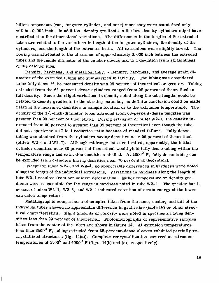
billet components (can, tungsten cylinder, and core) since they were maintained only within *O. 005 inch. In addition, density gradients in the low-density cylinders might have contributed to the dimensional variations. tubes a re related to the variations in length of the tungsten cylinders, the density of the cylinders, and the length of the extrusion butts. All extrusions were slightly bowed. bowing was attributed to the clearance of approximately 0.030 inch between the extruded tubes and the inside diameter of the catcher device and to a deviation from straightness of the catcher tube.
Density, hardness, and metallography. - Density, hardness, and average grain di- ameter of the extruded tubing are summarized in table IV. The tubing was considered to be fully dense if the measured density was 99 percent of theoretical or greater. extruded from the 65-percent-dense cylinders ranged from 95 percent of theoretical to f u l l density. Since the slight variations in density noted along the tube lengths could be related to density gradients in the starting material, no definite conclusion could be made relating the measured densities to sample location or to the extrusion temperature. The density of the 3/8-inch-diameter tubes extruded from 68-percent-dense tungsten was greater than 99 percent of theoretical. During extrusion of billet W2-1, the density in- creased from 80 percent to greater than 99 percent of theoretical even though the tube did not experience a 17 to 1 reduction ratio because of mandrel failure. tubing was obtained from the cylinders having densities near 95 percent of theoretical (billets W2-6 and W2-7). Although midrange data a re limited, apparently, the initial cylinder densities near 80 percent of theoretical would yield fully dense tubing within the temperature range and extrusion conditions studied. At 4000' F, fully dense tubing can be extruded from cylinders having densities near 70 percent of theoretical.
along the length of the individual extrusions. tube W2- 1 resulted from nonuniform deformation. dients were responsible for the range in hardness noted in tube W2-4. The greater hard- nesses of tubes W2-1, W2-3, and W2-4 indicated retention of strain energy at the lower extrusion temperature.
Metallographic comparisons of samples taken from the nose, center, and tail of the individual tubes showed no appreciable difference in grain size (table IV) or other struc- tural characteristics. Slight amounts of porosity were noted in specimens having den- sities less than 99 percent of theoretical. Photomicrographs of representative samples taken from the center of the tubes a re shown in figure 14. At extrusion temperatures less than 3500' F, tubing extruded from 65-percent-dense sleeves exhibited partially re- crystallized structures (fig. 14(a)). Complete recrystallization occurred at extrusion temperatures of 3500' and 4000' F (figs. 14(b) and (c), respectively).
The differences in the lengths of the extruded
The
Tubing
Fully dense
Except for tubes W2-1 and W2-4, no appreciable differences in hardness were noted Variations in hardness along the length of
Either temperature or density gra-
19

(a) Tube W2-3; extrusion temperature, 3400" F. X750.
I
(b) Tube W2-7; extrusion temperature, 3500" F. X250.
I -
0 i # .
I
f'+ -
~ I" t i
(c) Tube W3-3; extrusion temperature, 4000" F. X250. Figure 14. - Representative microstructures of longitudinal sections
of extruded tungsten tubing. Etchant, Murakami's reagent. Ex- t rus ion direct ion was from bottom to top of photomicrograph.
20

TABLE V. - STRENGTH O F EXTRUDED TUNGSTEN TUBING UNDER TENSILE AND
BIAXIAL STRESS AT 3500’ F
Tube
W2-3
W2-5
W2-6
W 2 -7
w3-3
Extrusion temper-
ature, OF
3400
4000
4000
~
3 500
4000
Tubing density, percent
*cor etical
~
~
Nominal tubing
iiameter , in.
1/2
1/2
1/2
1/2
3/8
Ultimate tensile
iitrength, psi
a9600 8400
Jocation o ensile tes specimen
Center Center
Average angential stress at failure,
psi
Location oi pressur-
za t ion test specimen
98 98
>99 a8700 8600
“9500 8300
Nose Center Center Center
>99 9200 9300
Tail Tail
10 200 10 800 9 800
Tail Nose Nose
>99 9 600 9 800
b7 400
Nose Center Center
b7 500 9 500
Nose Center
aElectropolished prior to test. bFailed outside of hot zone.
Mechanical properties. - The 3500’ F tensile strengths of the tubing specimens, ranging from 8300 to 9600 pounds per square inch, a re comparable to the reported strength of wrought sintered tungsten (ref. 3). From the limited number of tests made, the variation in strengths could not be attributed to specimen location with respect to the extruded tube, to specimen density, o r to the ex- trusion temperature. was attributed to the removal of surface irregularities present after machining. The high strengths obtained from tube W2-6 (95 percent dense cylinder) may be related to the dif- ference in starting material.
tangential stress at failure, ranging from 9500 to 10 800 pounds per square inch. could not be related to specimen location with respect to the extruded tubes or to the processing conditions. could not be definitely established but probably resulted from a localized thin section. The higher strengths obtained during pressurization (compared with the tensile strength)
These data a re summarized in table V.
The apparent increase in strength as a result of electropolishing
Results of the tube pressurization tests are summarized in table V. The average
The cause for failure outside of the hot zone on two specimens
2 1

(a) Tensile fracture; longitudinal section.
(b) Fracture under biaxial stress; t ransverse section. Figure 15. -Typical fractures of extruded tungsten tub ing under tensi le and biaxial stress conditions
at 3500" F. Etchant, Murakami's reagent. XlH).
22

c-sa-257;
Figure 16. -Tungsten tubing 318 inch in diameter fractured at 3500" F by internal pressurization. Average tangential stress at failure, 95W pounds per square inch.
were attributed to the biaxial s t ress state present during pressure testing. If the effec- tive s t ress criterion is used and ideal s t ress conditions a r e assumed, the uniaxial tensile s t ress can be shown to be approximately 0.87 of the tangential stress.
Metallographic examinations of failed tensile- and burst-test specimens showed that the mechanism of failure was intergranular with appreciable grain boundary void forma- tion. The mode of failure can be noted in the photomicrographs of figure 15. A some- what greater ductility was present in the specimens that failed during the burst test a s compared with specimens tested in tension, but values for ductility could not be determined accurately because of the shape of the tensile specimens and the nature of the burst test. The extent of the ductile failure in samples subjected to biaxial s t ress can be noted in figure 16. The 3/8-inch-diameter tube was fractured in a brittle manner adjacent to the high-temperature failure during removal from the test assembly.
CONCLUDING REMARKS
The results of this study have shown the feasibility of extruding 1/2- and 3/8-inch- diameter thin-wall tungsten tubing using the floating- mandrel technique. Additional development efforts a re required to optimize extrusion parameters. The technique developed may be adaptable to the fabrication of similar size tubing from the stronger solid solution or dispersion-strengthened alloys of tungsten. With improved lubrication techniques, extrusion of smaller diameter and thinner wall tubing may be possible. Slight modification of the canning technique, such a s the use of a steel shell (ref. l), may permit mandrel extrusion of tubing at lower temperatures where a high degree of cold work could be induced. In addition to the enhancement of mechanical properties, a cold-worked structure would be desirable for subsequent working operations such a s
23
warm drawing for final sizing.
rial, longer lengths of tubing could be obtained with the use of high-density cylinders. Extrusion of tungsten tubing 10 feet in length might be feasible.
Although fully dense tubing was extruded from relatively low-density starting mate-
SUMMARY OF RESULTS
Extrusion of small-diameter, thin-wall tungsten tubing was investigated using the
1. Both 1/2- and 3/8-inch-diameter tungsten tubing having a nominal wall thickness floating- mandrel technique.
of 0.020 inch were extruded successfully over 0.4- and 0.3-inch-diameter mandrels, respectively. Maximum usable length was 5 feet.
3000' to 4000' F. perature of 4000' F.
3. Within the temperature range investigated, 3000' to 4000' F, fully dense tubing was extruded from tungsten cylinders having a density near 80 percent of theoretical or greater. At 4000 dense cylinders.
within *O. 001 and *O. 005 inch, respectively. The best 1/2-inch-diameter tubing ex- hibited similar diametrical tolerances and wall thicknesses within *O. 002 inch.
ble to that of wrought sintered tungsten. Tubing subjected to a biaxial stress by internal pressurization at 3500 F exhibited an average tangential stress at failure ranging from 9500 to nearly 11 000 pounds per square inch.
The results are summarized as follows:
2. Successful extrusion temperatures for the 1/2-inch-diameter tubing ranged from Tubing with a 3/8-inch diameter was extruded successfully at a tem-
0 F, fully dense tubing was obtained from either 65- or 68-percent-
4. The wall thicknesses and diameters of the best 3/8-inch-diameter tubing were
5. The tensile strength of the extruded tubing at 3500' (8300 to 9600 psi) is compara-
0
Lewis Research Center, National Aeronautics and Space Administration,
Cleveland, Ohio, September 16, 1966, 129-03-14-03-22.
24

REFER EN CES
1. Isserow, S.; Hunt, J. G.; Jenkins, R. G.; andGeary, A. L.: Fundamental and Applied Research and Development in Metallurgy. II. Fabrication of Seamless Tungsten and Tungsten-Rhenium Tubing. Rep. No. NMI- 1264, Nuclear Metals, Inc., June 15, 1965.
2. Gyorgak, Charles A. : Extrusion at Temperatures Approaching 5000' F. NASA TN D-3014, 1965.
3. Sikora, Paul F. ; and Hall, Robert W. : High-Temperature Tensile Properties of Wrought Sintered Tungsten. NASA TN D-79, 1959.
NASA-Langley, 1966 E- 3577 25

. .. . . . , I
. . ’+, .
“The aeronautical and space activities of the United States shall be conducted so as to contribute . . . to the expansion of hriman Rnowl- edge of phenomena in the atmosphere and space. The Administration shall provide for the widest’ practicable and appropriate dissemination of information concerning its activities and the results thereof .”
-NATIONAL AERONAUnCS AND SPACE ACT OF 1928 ., .. .. ) .
, _ , , . . . . . . . ’. , ..
: 1. : , I . . . . . . , ._ ...- , . - .
> . . . . . ... . .
NASA SCIENTIFIC AND TECHNICAL PUBLICATIONS
TECHNICAL REPORTS: important, complete, and a lasting contribution to existing knowledge.
TECHNICAL NOTES: of importance as a contribution to existing knowledge.
TECHNICAL MEMORANDUMS: Information receiving limited distri- bution because of preliminary data, security classification, or other reasons.
CONTRACTOR REPORTS: Technical information generated in con- nection with a NASA contract or grant and released under NASA auspices.
Scientific and technical information considered
Information less broad in scope but nevertheless
TECHNICAL TRANSLATIONS: Information published in a foreign language considered to merit NASA distribution in English.
TECHNICAL REPRINTS: Information derived from NASA activities and initially published in the form of journal articles.
SPECIAL PUBLICATIONS: Information derived from or of value to @ASA* activities but not necessarily reporting the results of individual
” NASA-piogrammed scientific efforts. Publications include conference proceedings, monographs, data compilations, handbooks, sourcebooks, and special bibliographies.
Details on the availability o f these publications may be obtained from:
SCIENTIFIC AND TECHNICAL INFORMATION DIVISION
NATIONAL AERONAUTICS AND SPACE ADMINISTRATI,ON .i .
Washington, D.C. 20546
. . ..