experimental thermal and fluid scienceresearch.engr.oregonstate.edu/liburdygroup/sites/... ·...
TRANSCRIPT

Experimental Thermal and Fluid Science xxx (2009) xxx–xxx
ARTICLE IN PRESS
Contents lists available at ScienceDirect
Experimental Thermal and Fluid Science
journal homepage: www.elsevier .com/ locate/et fs
Simultaneous droplet impingement dynamics and heat transferon nano-structured surfaces
Jian Shen, Christof Graber, James Liburdy *, Deborah Pence, Vinod NarayananMechanical Engineering, Oregon State University, 204 Rogers Hall, Corvallis, OR 97331-6001, USA
a r t i c l e i n f o a b s t r a c t
Article history:Received 23 November 2008Received in revised form 14 February 2009Accepted 14 February 2009Available online xxxx
Keywords:Droplet impingementDroplet heat transferNano-structured surface heat transfer
0894-1777/$ - see front matter � 2009 Elsevier Inc. Adoi:10.1016/j.expthermflusci.2009.02.003
* Corresponding author. Tel.: +1 541 737 7017; faxE-mail address: [email protected] (J. Liburdy).
Please cite this article in press as: J. Shen(2009), doi:10.1016/j.expthermflusci.2009
This study examines the hydrodynamics and temperature characteristics of distilled deionized waterdroplets impinging on smooth and nano-structured surfaces using high speed (HS) and infrared (IR)imaging at We = 23.6 and Re = 1593, both based on initial drop impingement parameters. Results for asmooth and nano-structured surface for a range of surface temperatures are compared. Droplet impactvelocity, transient spreading diameter and dynamic contact angle are measured. The near surface averagedroplet fluid temperatures are evaluated for conditions of evaporative cooling and boiling. Also includedare surface temperature results using a gold layered IR opaque surface on silicon. Four stages of theimpingement process are identified: impact, boiling, near constant surface diameter evaporation, andfinal dry-out. For the boiling conditions there is initial nucleation followed by severe boiling, then nearconstant diameter evaporation resulting in shrinking of the droplet height. When a critical contact angleis reached during evaporation the droplet rapidly retracts to a smaller diameter reducing the contact areawith the surface. This continues as a sequence of retractions until final dry out. The basic trends are thesame for all surfaces, but the nano-structured surface has a lower dissipated energy during impact andenhances the heat transfer for evaporative cooling with a 20% shorter time to achieve final dry out.
� 2009 Elsevier Inc. All rights reserved.
1. Introduction and background
The use of spray cooling has been shown to be an effectivemeans for efficient thermal control. As such the impingementhydrodynamics and the thermal response of impacting dropletshave been studied for a wide range of conditions. However, manydetails of the impingement process and the resultant heat transferare still unanswered. The complexities associated with the sprayimpact including droplet deformation, impingement flow charac-teristics, surface tension effects in the contact line region and localheat transfer are not fully understood. A better knowledge of theseprocesses is important in designing an affective cooling system. Inthis study, we examine droplet impact without splashing and inparticular, how the impact and resultant thermal response is influ-enced by a specific nano-structured surface with boiling and non-boiling heating.
Spray cooling on micro-structured surfaces, such as straight, cu-bic, and pyramid fins, has been shown to enhance heat transfercompared with smooth surfaces, Silk et al. [1,2]. They showed anincrease in critical heat flux and that the enhancement in heat fluxdid not scale with increased surface area. It might be concludedthat the surface effect on the droplet spreading and thermal re-
ll rights reserved.
: +1 541 737 2600.
et al., Simultaneous droplet.02.003
sponse was most important since the pin height seemed to havelittle affect on overall heat transfer.
Micro-structured surfaces have also been studied relative totheir influence on overall heat transfer rates. Hsieh and Yao [3]used a dilute spray with micro-structured silicon surfaces. Theirsurface consisted of micro-studs with geometry variations usingsquare studs on the order of 160–480 lm high. They showedthat a Bond number, based on the micro-groove dimension, fornon-boiling conditions helps to characterize the enhanced heattransfer arguing that it provides a measure of the relative surfacetension forces. Four regimes were identified: flooded, thin film,partial dry-out and dry-out. The micro-structures are most sui-ted in the thin film and partial dry-out regimes because of thewetting enhancement. Further studies on micro-structured sur-faces by Sodtke and Stephan [4] based on cone shaped structureswere carried out using infrared imaging. The surface structureswere in the range of 75–225 lm high. They demonstrated thatmicro-structured surfaces leads to increased contact line lengthand thereby increase the overall heat flux. This implies thatthe film thickness near the contact line region thins due to themicro-structured surface. Kandlikar and Steinke [5] found thatthe contact angles first decrease, then increase with increasingsurface roughness.
Pool boiling, as influenced by a micro-porous coated surfacewas studied by Li and Peterson [6]. This investigation examined
impingement dynamics and heat transfer ..., Exp. Therm. FluidSci.
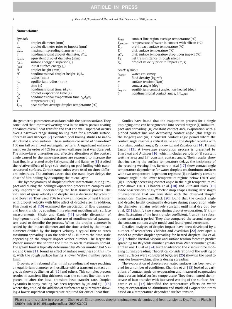
Nomenclature
Symbolsd droplet diameter (mm)do droplet diameter prior to impact (mm)dmax maximum spreading diameter (mm)d* nondimensional droplet diameter, d/do
dequiv equivalent droplet diameter (mm)Ediss surface energy dissipation (J)Einit initial surface energy (J)H droplet height (mm)H* nondimensional droplet height, H/do
r radius (mm)req equilibrium radius (mm)t time (s)t* nondimensional time, tdo/vo
tev droplet evaporation time (s)t*ev nondimensional evaporation time tevdo/vo
T temperature (�C)Tave near surface average droplet temperature (�C)
Tedge contact line region average temperature (�C)TA,water temperature of water in contact with silicon (�C)Ts,o pre-impact surface temperature (�C)Ts disk surface temperature (�C)DTs disk surface temperature drop upon impact (�C)�TSi net transmittance through siliconvo droplet velocity prior to impact (m/s)
Greek symbolsewater water emissivityq fluid density (kg/m3)r surface tension (N/m)h contact angle (deg)heq NH equilibrium contact angle, non-heated (deg)h nondimensional contact angle, h/heq,NH
2 J. Shen et al. / Experimental Thermal and Fluid Science xxx (2009) xxx–xxx
ARTICLE IN PRESS
the geometric parameters associated with the porous surface. Theyconcluded that improved wetting area in the micro-porous coatingenhances overall heat transfer and that the wall superheat occursover a narrower range during boiling than for a smooth surface.Sriraman and Banerjee [7] extended pool boiling studies to nano-structured silicon surfaces. These surfaces consisted of ‘‘nano-fins”100 nm tall on a fixed rectangular pattern. A significant enhance-ment, on the order of 40% for a given wall superheat was observed.The micro-layer disruption and effective alteration of the contactangle caused by the nano-structures are reasoned to increase theheat flux. In a related study Sathyamurthi and Banerjee [8] studiedthe relative effects of large sub-cooling on pool boiling with nano-structured surfaces. Carbon nano-tubes were used on three differ-ent substrates. The authors assert that the nano-layer delays theonset of film boiling by disrupting the micro-layer.
The hydrodynamics of droplet-surface interactions during im-pact and during the boiling/evaporation process are complex andvery important in understanding the heat transfer process. Theinfluence of spray velocity and droplet size is discussed by Schmidtand Boye [9]. They used PDA to show an increase of heat transferwith droplet velocity with little affect of droplet size. In addition,Bhardwaji et al. [10] examined the association of flow dynamicsand heat transfer by coupling finite element modeling with surfacemeasurements. Sikalo and Ganic [11] provide discussion ofimpingement and illustrated the use of nondimensional parame-ters used to describe the process. When the droplet diameter isscaled by the impact diameter and the time scaled by the impactdiameter divided by the impact velocity a typical time to reachmaximum spreading is on the order of 1–10 times the time scaledepending on the droplet impact Weber number. The larger theWeber number the shorter the time to reach maximum spread.The splash limit is typically determined by Weber number, but Sik-alo and Ganic [11] found an effect of surface roughness on this lim-it, with the rough surface having a lower Weber number splashlimit.
Droplets will rebound after initial spreading and once reachingan equilibrium diameter will oscillate with a transient contact an-gle, as shown by Shen et al. [12] and others. This complex processresults in transient film thickness near the contact line that is ex-pected to alter the local, transient heat transfer rate. Dropletdynamics in spray cooling has been reported by Jai and Qiu [13]where they studied the addition of surfactants to pure water show-ing a lower superheat temperature required for critical heat flux.
Please cite this article in press as: J. Shen et al., Simultaneous droplet(2009), doi:10.1016/j.expthermflusci.2009.02.003
Studies have found that the evaporation process for a singleimpinging drop can be segmented into several stages: (i) initial im-pact and spreading (ii) constant contact area evaporation with apinned contact line and decreasing contact angle (this stage isthe longest) and (iii) a constant contact angle period where thecontact angle reaches a critical value and the droplet recedes witha constant contact angle, Rymkiewicz and Zapalowicz [14], Hu andLarson [15]. A two-stage evaporation process is presented byBhardwaj and Attinger [16] which includes periods of (i) constantwetting area and (ii) constant contact angle. Their results showthat increasing the surface temperature delays the incipience ofthe receding wetting line. Bernardin et.al [17] show contact angletemperature dependence for water droplets on aluminum surfaceswith two temperature-dependent regimes: (i) a relatively constantcontact angle in the lower temperature regime, below 120 �C and(ii) a linearly decreasing contact angle in the high temperature re-gime above 120 �C. Chandra et al. [18] and Ruiz and Black [19]made observations of asymmetric drop shapes during later stagesof evaporation that are consistent with the observed dropletretractions. Crafton and Black [20] found that the contact angleand droplet height continually decrease during evaporation whilethe diameter remains relatively constant until final dry out. Leeet al. [21] identify two stages during droplet evaporation: (i) tran-sient fluctuation of the heat transfer coefficient, h, and (ii) a subse-quent constant h period. They also compared the second stage tothe constant contact angle model and found good agreement.
Detailed analyses of droplet impact have been developed by anumber of researchers. Chandra and Avedisian [22] developed amodel to predict droplet spreading for heated droplets. Ilia et al.[23] included inertial, viscous and surface tension forces to predictspreading for Reynolds number greater than Weber number great-er than one. Liu at al. [24] further advanced the viscous force mod-eling during spreading. Theoretical considerations of the wetting ofrough surfaces were considered by Quere [25] showing the need toconsider hemi-wicking effects during spreading.
The evaporation of droplets on heated surfaces has been evalu-ated for a number of conditions. Chandra et al. [18] looked at vari-ations of contact angle on evaporation and measured evaporationtimes versus initial surface temperature. They documented the in-crease of heat transfer with increased wetting of the surface. Ber-nardin et al. [17] identified the temperature effects on waterdroplet evaporation on aluminum and modeled evaporation timesbased on a temperature dependent surface tension.
impingement dynamics and heat transfer ..., Exp. Therm. FluidSci.
J. Shen et al. / Experimental Thermal and Fluid Science xxx (2009) xxx–xxx 3
ARTICLE IN PRESS
Several studies have used IR imaging to determine characteris-tics of droplet heat transfer. For instance, di Marzo et al. [26] stud-ied droplet evaporation rates, Freund et al. [27] evaluated localheat transfer coefficients in spray cooling using an oscillation IRtechnique and Tarozzi et al. [28] used a high emissivity coatingon the surface to effectively measure the surface temperature inthe liquid contact region of drop-wise cooling.
The objectives of the current study are to further detail the ef-fects of a nano-structured silicon surface on single dropletimpingement evaporative (non-boiling) and boiling heat transfer.A single droplet is used to impinge onto a silicon surface and thetransient hydrodynamics and thermal response are simultaneouslymeasured for evaporating and boiling conditions. Results are com-pared for a polished silicon surface and the nano-structured sur-face. Droplet near wall fluid transient temperature data areobtained using infra-red imaging. In addition, the surface temper-ature is also measured in separate runs using a thin deposited goldlayer on the polished silicon surface. The gold layer allows directinfra-red imaging of the solid surface rather than the fluid.
2. Experimental set-up
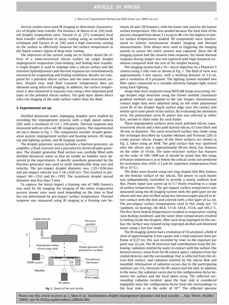
Distilled deionized water impinging droplets were studied byrecording the impingement process with a high speed camera(HS) with a resolution of 512 � 256 pixels. Thermal response wasmeasured with an infra-red (IR) imaging system. The experimentalset-up is shown in Fig. 1. The components include: droplet gener-ation system, impingement surface and heating system, HS imag-ing and lighting system, and IR imaging system.
The droplet generator system includes a function generator, anamplifier, a fluid reservoir and a piezoelectric driven droplet gener-ator. The droplet generator fluid section was carefully filled withdistilled deionized water so that no visible air bubbles were ob-served in the experiments. A specific waveform generated by thefunction generator was used to yield reproducible drop size andvelocity. The pre-impact droplet diameter was 1.29 ± 0.04 mmand pre-impact velocity was 1.18 ± 0.02 m/s. This resulted in pre-impact We = 23.6 and Re = 1593. The maximum droplet spreaddiameter was less than 3 mm.
To capture the initial impact a framing rate of 7400 frames/swas used for HS imaging. For imaging of the entire evaporativeprocess slower rates were used depending on the time to finaldry out determined by pre-impact surface temperature. Thermalresponse was measured using IR imaging at a framing rate be-
Fig. 1. Sketch of the test facility.
Please cite this article in press as: J. Shen et al., Simultaneous droplet(2009), doi:10.1016/j.expthermflusci.2009.02.003
tween 10 and 120 frames/s, with the lower rate used for the lowestsurface temperature. This was needed because the total time of theprocess changed from about 2 s to up to 48 s for the highest to low-est surface temperatures studied. All components were synchro-nized to achieve simultaneous droplet imaging and thermalmeasurements. Time delays were used in triggering the imagingsystem to assure the entire process was captured. Since the IRimaging system had the slowest time response, the initial thermalresponse during impact was not captured with high temporal res-olution compared with the rest of the droplet heating.
The imaging system had a 10�micro-objective on a Phantom 5camera using a side view as shown in Fig. 1. The field of view wasapproximately 5 mm square, with a working distance of 3.5 cm,and a resolution of 9 lm/pixel. The lighting system included twofiber optics connected to a variable intensity halogen light sourceusing back lighting.
Image data were analyzed using MATLAB image processing. Im-age droplet edge detection using the Prewit method (maximumgradient method) was applied to the raw images. Instantaneouscontact angle data were obtained using an nth order polynomialcurve fit of the droplet liquid surface edge near the contact linewithin up to nine pixels of the surface. By evaluating the minimumerror, the polynomial curve fit power law was selected as eitherfirst, second or third order for each frame.
Three impingement surfaces were used, polished silicon, nano-structured silicon and a thin gold layered silicon, 0.5 mm thick and38 mm in diameter. The nano-structured surface was made usingthe technique described by Gauther-Manuel and Pichonat [29] tocreate porous silicon. Images of the three surfaces are shown inFig. 2, taken using an AFM. The gold surface that was sputteredonto the silicon and is approximately 60 nm thick, has featureson the order of 10 nm. The nano-structure surface has featureson the order of 100–1000 nm. It should be noted that this rangeof feature dimension is at or below the critical cavity size predictedfor nucleation sites (0.65–3.3 lm for superheat temperatures from50 to 10 �C).
The disks were heated using two ring shaped thin film heaterson the bottom surface of the silicon. The power to each heaterwas independently controlled to provide a nearly uniform heatflux. Power input was varied up to 5.7 Watts resulting in a rangeof surface temperatures. The pre-impact surface temperature wasmeasured using the IR imaging system with the gold layer on thesilicon and was also verified using two thermocouples placed in di-rect contact with the disk and covered with a thin layer of Ga–Sn.The pre-impact surface temperatures used in this study are: 23(ambient, no heating), 68, 86.8, 111.8, 143.8, 153.8, and 185.2 �C.The first three heated temperatures resulted in evaporative cooling(non-boiling condition) and the latter three temperatures resultedin boiling inside the droplets. After each drop impinged on the sur-face the surface was cleaned using isopropyl alcohol and deionizedwater using a lint free swab.
The IR imaging system had a resolution of 10 lm/pixel, a field ofview of approximately 4 mm square and a total exposure time perframe of 8.27 ms, this was recorded by rows so the exposure perpixel was 32 lm. The IR detection had contributions from the fol-lowing: radiation emitted by water in contact with the surface (thedesired source), noise from the IR camera optics, radiation from thecooled detector and the surroundings that is reflected from the sil-icon disk surface, and radiation emitted by the silicon disk andmanifold. Attenuation of radiation occurs due to the participatingmedium (air, CO2) between the IR camera and the disk. In additionto the noise, the radiation varies due to the configuration factor be-tween the surface and the focal plane array. The reflected sur-rounding radiation incident upon the heat sink is considerednegligible since the configuration factor from the surroundings tothe heat sink is on the order of 10-4. The reflected specular
impingement dynamics and heat transfer ..., Exp. Therm. FluidSci.
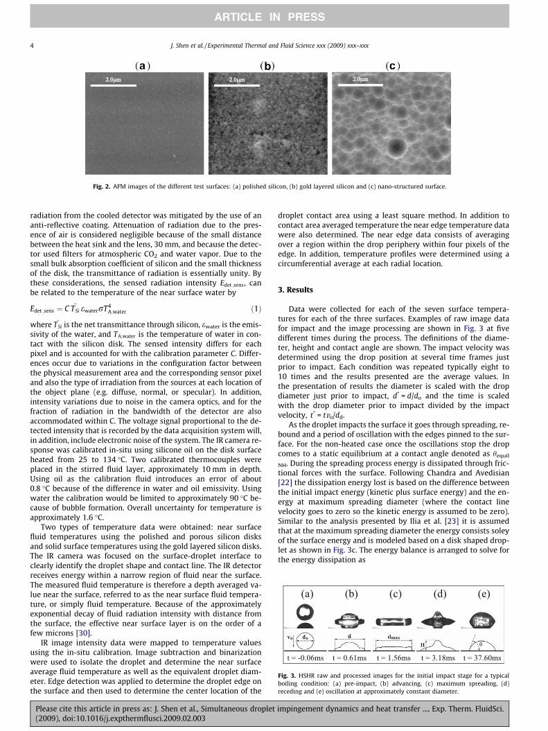
Fig. 2. AFM images of the different test surfaces: (a) polished silicon, (b) gold layered silicon and (c) nano-structured surface.
(a) (b) (c) (d) (e)
t = -0.06ms t = 0.61ms t = 1.56ms t = 3.18ms t = 37.60ms
Fig. 3. HSHR raw and processed images for the initial impact stage for a typicalboiling condition: (a) pre-impact, (b) advancing, (c) maximum spreading, (d)receding and (e) oscillation at approximately constant diameter.
4 J. Shen et al. / Experimental Thermal and Fluid Science xxx (2009) xxx–xxx
ARTICLE IN PRESS
radiation from the cooled detector was mitigated by the use of ananti-reflective coating. Attenuation of radiation due to the pres-ence of air is considered negligible because of the small distancebetween the heat sink and the lens, 30 mm, and because the detec-tor used filters for atmospheric CO2 and water vapor. Due to thesmall bulk absorption coefficient of silicon and the small thicknessof the disk, the transmittance of radiation is essentially unity. Bythese considerations, the sensed radiation intensity Edet ;sens, canbe related to the temperature of the near surface water by
Edet ;sens ¼ C TSi ewaterrT4A;water ð1Þ
where TSi is the net transmittance through silicon, ewater is the emis-sivity of the water, and TA;water is the temperature of water in con-tact with the silicon disk. The sensed intensity differs for eachpixel and is accounted for with the calibration parameter C. Differ-ences occur due to variations in the configuration factor betweenthe physical measurement area and the corresponding sensor pixeland also the type of irradiation from the sources at each location ofthe object plane (e.g. diffuse, normal, or specular). In addition,intensity variations due to noise in the camera optics, and for thefraction of radiation in the bandwidth of the detector are alsoaccommodated within C. The voltage signal proportional to the de-tected intensity that is recorded by the data acquisition system will,in addition, include electronic noise of the system. The IR camera re-sponse was calibrated in-situ using silicone oil on the disk surfaceheated from 25 to 134 �C. Two calibrated thermocouples wereplaced in the stirred fluid layer, approximately 10 mm in depth.Using oil as the calibration fluid introduces an error of about0.8 �C because of the difference in water and oil emissivity. Usingwater the calibration would be limited to approximately 90 �C be-cause of bubble formation. Overall uncertainty for temperature isapproximately 1.6 �C.
Two types of temperature data were obtained: near surfacefluid temperatures using the polished and porous silicon disksand solid surface temperatures using the gold layered silicon disks.The IR camera was focused on the surface-droplet interface toclearly identify the droplet shape and contact line. The IR detectorreceives energy within a narrow region of fluid near the surface.The measured fluid temperature is therefore a depth averaged va-lue near the surface, referred to as the near surface fluid tempera-ture, or simply fluid temperature. Because of the approximatelyexponential decay of fluid radiation intensity with distance fromthe surface, the effective near surface layer is on the order of afew microns [30].
IR image intensity data were mapped to temperature valuesusing the in-situ calibration. Image subtraction and binarizationwere used to isolate the droplet and determine the near surfaceaverage fluid temperature as well as the equivalent droplet diam-eter. Edge detection was applied to determine the droplet edge onthe surface and then used to determine the center location of the
Please cite this article in press as: J. Shen et al., Simultaneous droplet(2009), doi:10.1016/j.expthermflusci.2009.02.003
droplet contact area using a least square method. In addition tocontact area averaged temperature the near edge temperature datawere also determined. The near edge data consists of averagingover a region within the drop periphery within four pixels of theedge. In addition, temperature profiles were determined using acircumferential average at each radial location.
3. Results
Data were collected for each of the seven surface tempera-tures for each of the three surfaces. Examples of raw image datafor impact and the image processing are shown in Fig. 3 at fivedifferent times during the process. The definitions of the diame-ter, height and contact angle are shown. The impact velocity wasdetermined using the drop position at several time frames justprior to impact. Each condition was repeated typically eight to10 times and the results presented are the average values. Inthe presentation of results the diameter is scaled with the dropdiameter just prior to impact, d* = d/do and the time is scaledwith the drop diameter prior to impact divided by the impactvelocity, t* = tvo/dd.
As the droplet impacts the surface it goes through spreading, re-bound and a period of oscillation with the edges pinned to the sur-face. For the non-heated case once the oscillations stop the dropcomes to a static equilibrium at a contact angle denoted as hequil
NH. During the spreading process energy is dissipated through fric-tional forces with the surface. Following Chandra and Avedisian[22] the dissipation energy lost is based on the difference betweenthe initial impact energy (kinetic plus surface energy) and the en-ergy at maximum spreading diameter (where the contact linevelocity goes to zero so the kinetic energy is assumed to be zero).Similar to the analysis presented by Ilia et al. [23] it is assumedthat at the maximum spreading diameter the energy consists soleyof the surface energy and is modeled based on a disk shaped drop-let as shown in Fig. 3c. The energy balance is arranged to solve forthe energy dissipation as
impingement dynamics and heat transfer ..., Exp. Therm. FluidSci.

Table 1Equilibrium contact angle and surface energy dissipation for non-heating condition.
Surface Equilibrium contact angle heq NH ± std, (deg) Ediss /Einitial
Polished 46 ± 1 0.38 ± 0.02Gold 58 ± 3 0.18 ± 0.03Nano-structured 65 ± 1 0.11 ± 0.03
J. Shen et al. / Experimental Thermal and Fluid Science xxx (2009) xxx–xxx 5
ARTICLE IN PRESS
Ediss ¼p12
qv2od3
o þ 12d2or
� �� r 3d2
maxð1� cos hÞ þ 8d3
o
dmax
!" #
ð2Þ
where symbols are defined in the nomenclature. The results of thedissipated energy for the non-heated cases for the three surfaces areshown in Table 1 where the dissipated energy is normalized by thetotal initial energy. Also shown is the equilibrium contact angle foreach surface (measured after the droplet comes to static equilib-rium). The polished surface indicates a significantly larger loss ofinitial energy compared with the gold and nano-structured sur-faces. This is consistent with the much larger equilibrium contactangle for the latter surfaces. To help explain these differences thedetails of the impact processes are discussed below for these threesurfaces.
(a)
(b)
(c)
Fig. 4. Initial impact: diameter, d*, as a function of time, t*, (a) non-heated; (b) non-boiling Ts,o = 86.8 �C and (c) boiling Ts,o = 153.8 �C.
Please cite this article in press as: J. Shen et al., Simultaneous droplet(2009), doi:10.1016/j.expthermflusci.2009.02.003
The initial impact process is shown for non-boiling and boilingcases for the polished, gold layered and nano-structured surfaces.These results are averages over typically 10 runs. Fig. 4 shows rep-resentative nondimensional time traces of the droplet spreadingdiameter for non-heated, non-boiling and boiling cases. All casesshow a rapid initial spreading to a maximum diameter followedby a rebound. The maximum spreading for all cases occurs withint* < 2 and the initial rebound occurs within t* < 5. This correspondsto approximately 2.9 and 7.25 ms, respectively. To put this in per-spective, the total time for evaporation, shown later, ranges from2.09 to 48.3 s, for surfaces temperatures of 185.2 and 68.5 �C,respectively. Although the initial spreading is not significantly af-fected by the different surfaces, the equilibrium spreading diame-ter is different, with the largest occurring for the polished surface.This reduction in spreading for the gold and nano-structured sur-faces is consistent with the observed decrease in dissipated energyfor these cases. The non-boiling heated cases show a reduction inspreading for the polished and gold surface while the nano-struc-tured surface shows an increase. For the boiling cases all equilib-rium spreading diameters are shown to be reduced, with thenano-structured spreading diameter the largest for these cases.The increased spreading on the nano-structured surface suggestsa greater potential for increased heat transfer.
(a)
(b)
(c)
Fig. 5. Initial impact: height, H*, as a function of time, t*, (a) non-heated; (b) non-boiling Ts,o = 86.8 �C and (c) boiling Ts,o = 153.8 �C.
impingement dynamics and heat transfer ..., Exp. Therm. FluidSci.
(a) (b) (c)
t/tev = 0.000 t/tev = 0.018 t/tev = 0.211
(d) (e)
t/tev = 0.614 t/tev = 0.682
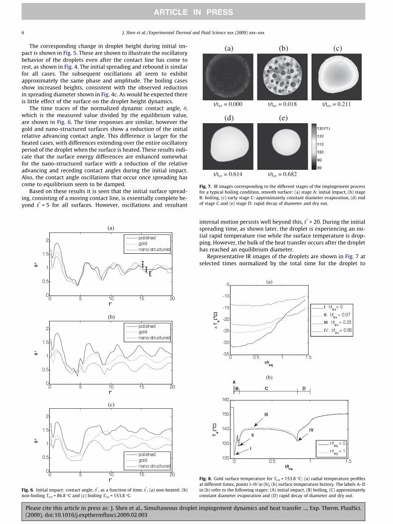
Fig. 7. IR images corresponding to the different stages of the impingement processfor a typical boiling condition, smooth surface: (a) stage A: initial impact, (b) stageB: boiling, (c) early stage C: approximately constant diameter evaporation, (d) endof stage C and (e) stage D: rapid decay of diameter and dry out.
6 J. Shen et al. / Experimental Thermal and Fluid Science xxx (2009) xxx–xxx
ARTICLE IN PRESS
The corresponding change in droplet height during initial im-pact is shown in Fig. 5. These are shown to illustrate the oscillatorybehavior of the droplets even after the contact line has come torest, as shown in Fig. 4. The initial spreading and rebound is similarfor all cases. The subsequent oscillations all seem to exhibitapproximately the same phase and amplitude. The boiling casesshow increased heights, consistent with the observed reductionin spreading diameter shown in Fig. 4c. As would be expected thereis little effect of the surface on the droplet height dynamics.
The time traces of the normalized dynamic contact angle, h,which is the measured value divided by the equilibrium value,are shown in Fig. 6. The time responses are similar, however thegold and nano-structured surfaces show a reduction of the initialrelative advancing contact angle. This difference is larger for theheated cases, with differences extending over the entire oscillatoryperiod of the droplet when the surface is heated. These results indi-cate that the surface energy differences are enhanced somewhatfor the nano-structured surface with a reduction of the relativeadvancing and receding contact angles during the initial impact.Also, the contact angle oscillations that occur once spreading hascome to equilibrium seem to be damped.
Based on these results it is seen that the initial surface spread-ing, consisting of a moving contact line, is essentially complete be-yond t* = 5 for all surfaces. However, oscillations and resultant
(a)
(b)
(c)
Fig. 6. Initial impact: contact angle, h*, as a function of time, t*, (a) non-heated; (b)non-boiling Ts,o = 86.8 �C and (c) boiling Ts,o = 153.8 �C.
Please cite this article in press as: J. Shen et al., Simultaneous droplet(2009), doi:10.1016/j.expthermflusci.2009.02.003
internal motion persists well beyond this, t* > 20. During the initialspreading time, as shown later, the droplet is experiencing an ini-tial rapid temperature rise while the surface temperature is drop-ping. However, the bulk of the heat transfer occurs after the droplethas reached an equilibrium diameter.
Representative IR images of the droplets are shown in Fig. 7 atselected times normalized by the total time for the droplet to
(a)
(b)
ºº
Fig. 8. Gold surface temperature for Ts,o = 153.8 �C: (a) radial temperature profilesat different times, points I–IV in (b), (b) surface temperature history. The labels A–Din (b) refer to the following stages: (A) initial impact, (B) boiling, (C) approximatelyconstant diameter evaporation and (D) rapid decay of diameter and dry out.
impingement dynamics and heat transfer ..., Exp. Therm. FluidSci.

(a)
(b)
ºº
Fig. 9. Near surface droplet temperature (Tave and Tedge), diameter (dequiv) andheight (H) as a function of nondimensional time (t/tev), polished surface, (a) boilingTs,o = 185.2 �C, (b) non-boiling Ts,o = 111.8 �C. The labels A–D refer to the followingstages: (A) initial impact, (B) boiling, (C) approximately constant diameterevaporation and (D) rapid decay of diameter and dry out.
J. Shen et al. / Experimental Thermal and Fluid Science xxx (2009) xxx–xxx 7
ARTICLE IN PRESS
evaporate, tev. The images correspond to stages A through D basedon the temperature time traces shown in Figs. 8 and 9, with the fol-lowing definitions: (A) initial impact, (B) boiling, (C) nearly con-stant diameter evaporation and (D) final dry out. Note that theboiling occurs relatively early but then stops after about 20% ofthe total evaporation time. As the drop evaporates the contact areais reduced until final dry-out.
The radial distribution of the gold layer surface temperature un-der the droplet is shown in Fig. 8a at four discrete times where theradial position is normalized by the equivalent radius measuredwhen the spreading has come to equilibrium, when t* = 15–20.The equivalent radius assumes the droplet contact surface area iscircular. The times of each radial distribution are denoted as Ithrough IV and correspond to the times shown in Fig. 8b, discussedbelow. The temperature is presented as DTs, the surface tempera-ture minus the pre-impact surface temperature. These resultsshow how the radial temperature gradient decreases over timeas the droplet is heated until the surface temperature is nearly uni-form during the final evaporation period.
Shown in Fig. 8b is the center surface temperature versus timefor the case of the pre-impact surface temperature of 153.8 �C. Thisis representative of all cases and is used to indicate stages and spe-cific times during the process, similar to those described in the lit-erature. Time I occurs in stage A, the initial impact where thesurface temperature experience a rapid drop. Time II occurs instage B and is the minimum temperature during the boiling period(for the cases where boiling occurs). Here the surface temperaturefirst rises after the initial cooling by impact. Then, once boiling be-gins the temperature drops to the minimum shown as time II. TimeIII is during stage C, a period of nearly constant temperature and is
Please cite this article in press as: J. Shen et al., Simultaneous droplet(2009), doi:10.1016/j.expthermflusci.2009.02.003
the majority of the time of the entire process. During this time thefluid temperature has risen (shown later) and the temperature dif-ference between the surface and fluid is not sufficient to maintainboiling. The lack of sufficient nucleation sites may be a cause for noobserved boiling. Also, the initial boiling may have been enhancedby trapped air in the droplet in the initial impact. Finally, time IV isat the time just before final dry-out, stage D, where the surfacetemperature reaches a minimum followed by fairly rapid surfacetemperature rise as dry-out occurs.
During stage C the droplet height decreases while the diameterstays nearly constant. This results in a decreasing contact angle.When this angle reaches a critical value the droplet is observedto make a near instantaneous jump to a smaller contact area withthe surface, resulting in a higher contact angle and higher dropletheight. The critical contact angle, for all surfaces, was measuredjust prior to this jump to a smaller contact diameter using thenth order polynomial curve fit as described previously. The resultswere obtained for all pre-impact surface temperatures and allthree surfaces. This critical contact angle was found to be on the or-der of 10� for all surfaces, being 9.9� for the polished surface, 8.8�for the gold surface and 11.2� for the nano-structured surface.These results are averages using all of the temperatures with astandard deviation of approximately 2�. No trends were found forthe range of surface temperatures. Immediately after the first drop-let contraction the contact angle was also measured for all cases.Here the results for the post-critical contact angles are 24�, 33�and 27� for the polished, gold layered, and nano-structured sur-faces, respectively. This indicates that the post critical angle is sig-nificantly less than the equilibrium contact angle which may be aresult of temperature effects on the fluid surface tensions (surfacetension decreases with increasing temperature, see Jasper [31]).
The near surface fluid temperature time traces are shown inFig. 9 for non-boiling and boiling conditions on the polished sur-face. The surface temperature is the average over the contact areaof the droplet. Also shown are the near edge fluid temperature,droplet height and equivalent diameter (assuming a circular con-tact area) versus time. The nano-structured and gold surface re-sults look very similar, with the same trends. Only the boilingcases have the stage B oscillations shown in Fig. 9a. Stage A showsthe rapid rise in fluid temperature until boiling occurs. In the non-boiling case, Fig. 9b, the temperature reaches a peak value early inthe process, by approximately t/tev = 0.1. After the boiling processsubsides the peak fluid temperature is reached. Both of these peaksoccur close to the time the surface temperature reaches its peak asit enters into stage C. For the boiling cases this period of evapora-tion occurs at superheated temperatures relative to the ambientpressure. During this time the droplet contact diameter remainsnearly constant. As shown in Fig. 9b the height is linearly decreas-ing until the end of stage C. During this time the edge temperaturefollows the same trend but is consistently lower than the contactarea average temperature by approximately 10�.
At the beginning of stage D, final dry-out, the drop evaporationcontinues, the height continues to decrease and once the criticalangle is reached the sudden decrease in contact area occurs overa series of events. During this time the temperature also goesthrough systematic jumps with a rise in temperature at each ofthe diameter decrease events. This may be a result of reduced heattransfer to the droplet because of a larger contact angle in that re-gion. It might also be because cooler fluid is being drawn in to-wards the center, as indicated in the radial distributions inFig. 8a. This final stage lasts for approximately the final 30% ofthe total evaporation time.
The total normalized evaporation times are shown in Fig. 10 forthe polished and nano-structured surfaces for each of the pre-im-pact surface temperatures. The evaporation times for the nano-structured surface are consistently lower than those for the
impingement dynamics and heat transfer ..., Exp. Therm. FluidSci.

º
Fig. 10. Evaporation time normalized by vo/do versus pre-impact surface temper-ature, Ts,o.
8 J. Shen et al. / Experimental Thermal and Fluid Science xxx (2009) xxx–xxx
ARTICLE IN PRESS
polished surface. The evaporation time difference is most pro-nounced at the lower surface temperatures, non-boiling, cases.The inset shows results for the boiling cases. Evaluating all casesit is found that the decrease of total evaporation time for thenano-structured surface remains at about 20% for all surface tem-peratures for both the non-boiling and boiling cases, except for thehighest surface temperature case. The decrease of the total evapo-ration time is believed to be a consequence of the increasedspreading diameter for the nano-structured heated cases. For thesame droplet size and velocity, this result may have consequencesin improving spray cooling applications. However, data needs to beextended to a large range of nano-structured surfaces looking atrelevant effects of size scales and surface characteristics.
4. Conclusions
This study investigates the simultaneous measurements ofheated droplet impingement hydrodynamics and near surface fluidtemperature measurements for a range of heating levels corre-sponding to droplet non-boiling and boiling conditions. Impinge-ment was on polished silicon, nano-structured porous silicon,and gold layered polished silicon. The nano-structured surfaceshows an increased equilibrium contact angle, indicative of re-duced wetting characteristics. The initial impact of the dropletswas found to be different in that the nano-structured surface re-sults in a significant reduction in energy dissipation during the ini-tial impact spreading. The equilibrium states, which occur duringnearly constant diameter and constant temperature evaporation,were found to be different. The equilibrium spreading diameter in-creases with heating for the nano-structured non-boiling and boil-ing cases compared with the polished surface. There are four majorstages identified during the total droplet evaporation process: im-pact, boiling (if the surface temperature is sufficiently high), nearlyconstant diameter evaporation and a final dry-out period. Impactoccurs within t* < 5 with a very rapid temperature rise. Boiling re-sults in large oscillations of the near surface fluid temperature, fol-lowed by a temperature rise. Constant diameter evaporationoccurs during approximately 60% of the total time with nearly con-stant fluid temperature and a constant decrease in droplet height.The final dry-out occurs in the last 30% of the total evaporationtime. A critical angle was measured to be near 10� when the drop-let retracts to a lower contact area and the fluid temperature risesrapidly. The critical angle does not change significantly with eithertemperature or surface. The corresponding contact angle after thiscritical jump was significantly lower than the equilibrium contactangle. Finally, the total droplet evaporation time was found to be
Please cite this article in press as: J. Shen et al., Simultaneous droplet(2009), doi:10.1016/j.expthermflusci.2009.02.003
reduced by approximately 20% using this nano-structured surfacecompared with the polished surface thought to be a consequenceof increased spreading.
References
[1] E.A. Silk, J. Kim, K. Kiger, Spray cooling of enhanced surfaces: impact ofstructured surface geometry and spray axis inclination, Int. J. Heat MassTransfer 49 (2006) 4910–4920.
[2] E.A. Silk, J. Kim, K. Kiger, Impact of cubic pin finned surface structure geometryupon spray cooling heat transfer, IPACK2005-73003, Proc. IPACK2005, ASMEInterPACK’05, San Francisco, CA, USA, 2005.
[3] C.-C. Hsieh, S.-C. Yao, Evaporative heat transfer characteristics of a water sprayon micro-structured silicon surfaces, Int. J. Heat Mass Transfer 49 (2006) 962–974.
[4] C. Sodtke, P. Stephan, Spray cooling on micro-structured surfaces, Int. J. HeatMass Transfer 50 (2007) 4089–4097.
[5] S. Kandlikar, M. Steinke, Contact angles and interface behavior during rapidevaporation of liquid on a heated surface, Int. J. Heat Mass Transfer 45 (2002)3771–3780.
[6] C. Li, G.P. Peterson, Parametric study of pool boiling on horizontal highlyconductive micro-porous coated surfaces, J. Heat Transfer 129 (2007) 1465–1475.
[7] S.R. Sriraman, D. Banerjee, Pool boiling studies on nano-structured surfaces,IMECE2.007-42581, Proc. IMECE2007, Seattle, WA, USA, 2007.
[8] V. Sathyamurthi, D. Banerjee, Pool boiling studies on nano-textured surfaces:impact of high subcooling, IMECE2007-42508, Proc. ASME IMECE2007, Seattle,WA, USA, 2007.
[9] J. Schmidt, H. Boye, Influence of velocity and size of droplets on the heattransfer in spray cooling, Chem. Eng. Technol. 24 (2001) 255–260.
[10] R. Bhardwaji, J.P. Longtin, D. Attinger, Interfacial heat transfer during dropletimpact on a solid surface: comparison of high resolution laser measurementswith finite element simulations, IMECE2007-43087, Proc. IMECE2007, Seattle,WA, USA, 2007.
[11] S. Sikalo, E.N. Ganic, Phenomena of droplet-surface interactions, Exp. Therm.Fluid Sci. 31 (2006) 97–110.
[12] J. Shen, J.A. Liburdy, D.V. Pence, V. Narayanan, Single droplet impingement:effect of nanoparticles, FEDSM2008-55192, Proc. ASME Fluids EngineeringConference, 2008.
[13] W. Jai, H.-H. Qiu, Experimental investigation of droplet dynamics and heattransfer in spray cooling, Exp. Therm. Fluid Sci. 27 (2003) 829–838.
[14] J. Rymkiewicz, Z. Zapalowicz, Analysis of the evaporation process for waterdroplet on flat heated surface, Int. Comm. Heat Mass Transfer 20 (1993) 687–697.
[15] H. Hu, R. Larson, Evaporation of a sessile droplet on a substrate, J. Phys. Chem.B 106 (2002) 1334–1344.
[16] R. Bhardwaj, D. Attinger, A numerical model for the evaporation of a nonoliterdroplet on a solid, heated substrate, IMECE2007-43088, Proc. IMECE2007,Seattle, WA, USA, 2007.
[17] J.D. Bernardin, I. Mudawar, C.B. Walsh, E.I. Franses, Contact angle temperaturedependence for water droplets on practical aluminum surfaces, Int. J. HeatMass Transfer 40 (1997) 1017–1033.
[18] S. Chandra, M. di Marzo, Y.M. Qiao, P. Tartarini, Effect of liquid–solid contactangle on droplet evaporation, Fire Safety J. 27 (1996) 141–158.
[19] O.E. Ruiz, W.Z. Black, Evaporation of water droplets placed on a heatedhorizontal surface, J. Heat Trans. 124 (2002) 854–863.
[20] E. Crafton, W. Black, Heat transfer and evaporation rates of small liquiddroplets on heated horizontal surfaces, Int. J. Heat Mass Transfer 47 (2004)1187–1200.
[21] J. Lee, J. Kim, K. Kiger, Time and space resolved heat transfer characteristics ofsingle droplet cooling using microscale heater arrays, Int. J. Heat Fluid Flow 22(2001) 188–200.
[22] S. Chandra, C.T. Avedisian, On the collision of a droplet with a solid-surface,Proc. Roy. Soc. Lond. Ser. A Math. Phys. Eng. Sci. (1991) 13–41.
[23] V. Ilia, R. Rioboo, C. Tropea, Normal impact of a liquid drop on a dry surface:model for spreading and receding, Proc. Roy. Soc. Lond. A 458 (2002) 1411–1430.
[24] J. Liu, W. Franco, G. Aguilar, Effect of surface roughness on single cryogendroplet spreading, J. Fluids Eng. 130 (4) (2008) 4021–4029.
[25] D. Quere, Rough ideas on wetting, Physica A 313 (2002) 32–46.[26] M. di Marzo, C.H. Kidder, P. Tartarini, Infrared thermography of drop-wise
evaporative cooling of a seminfinite solid subject to radiant heat input, Exp.Heat Transfer 5 (1992) 101–114.
[27] S. Freund, A.G. Pautsch, T.A. Shedd, S. Kabelac, Local heat transfer coefficientsin spray cooling systems measured with temperature oscillation IRthermography, Int. J. Heat Mass Transfer 50 (2007) 1953–1962.
[28] L. Tarozzi, A. Muscio, P. Tartarini, Experimental tests of dropwise cooling oninfrared-transparent media, Exp. Therm. Fluid Sci. 31 (2007) 857–865.
[29] B. Gauther-Manuel, T. Pichonat, Nanostructured membranes: a new class ofprotonic conductor for miniature fuel cells, J. Nanotech. Online 1 (2005) (July).
[30] V.A. Patil, V. Narayanan, Spatially resolved temperature measurement inmicrochannels, Microfluid. Nanofluid. 2 (4) (2006) 291–300.
[31] J.J. Jasper, The surface tension of pure liquid compounds, J. Phys. Chem. Ref.Data 1 (1972) 841–1010.
impingement dynamics and heat transfer ..., Exp. Therm. FluidSci.