experimental evaluation of a ruby maser at 43 ghz
TRANSCRIPT
IEEE TRANSACTIONS ON MfCROWAVE THEORY AND TECHNIQUES VOL. 30, NO. 1 I, NOVEMBER 1982 2013
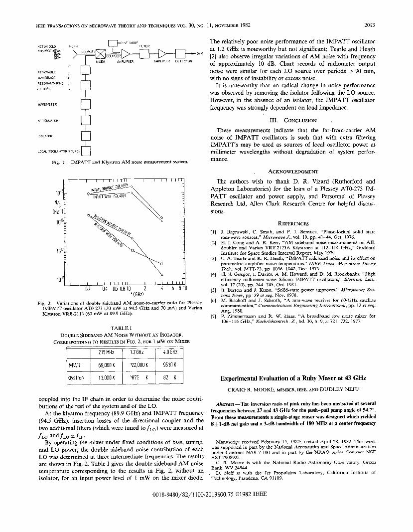
YNOISE DIODEHOTOR COLC HORN FILTER
ABSORBER
E
COUPLERDVM
> rRcOupL:~ AMPLIFIER DETECTOR
REMOVABLE
WAVEGUIDE
RESONANT- R!NG
FILTERS [$
WAVEMETER
ATTENUATOR
8
ISOLATOR
LOCAL OSCILLATOR SOURCE8
Fig. 1 IMPATT and Kfystron AM noise measurement system.
\A,[18_
I I I I I I I Ill I I I I I Ill
0.2 0.4 0.60.81.0 2 k 6 810f (GHz)
Fig. 2. Variations of double sidebaud AM nome-to-canier ratio for PlesseyIMPATT oscillator ATO 273 (30 mW at 94.5 GHz and 70 MA) aad Vnriarr
KfystronVRB-2113 (60 mW at 89.9 GHz).
The relatively poor noise performance of the IMPATT oscillator
at 1.2 GHz is noteworthy but not significant; Tearle and Heath
[2] also observe irregular variations of AM noise with frequency
of approximately 10 dB. Chart records of radiometer output
noise were similar for each LO source over periods >90 rein,
with no signs of instability or excess noise.
It is noteworthy that no radical change in noise performance
was observed by removing the isolator following the LO source.
However, in the absence of an isolator, the IMPATT oscillator
frequency was strongly dependent on load impedance.
III. CONCLUSION
These measurements indicate that the far-from-carrier AM
noise of IMPATT oscillators is such that with extra filtering
IMPATT’s may be used as sources of local oscillator power at
millimeter wavelengths without degradation of system perfor-
mance.
ACJCNOWLE~GMEN~
The authors wish to thank D. R. Vizard (Rutherford and
Appleton Laboratories) for the loan of a Plessey ATO-273 IM-
PATT oscillator and power supply, and Personnel of Plessey
Research Ltd, Allen Clark Research Centre for helpful discus-
sions.
[1]
[2]
[3]
[4]
[5]
[6]
[7]
REFERENCES
J. Baprawski, C. %mth, and F. J. Bemues, “ Phase-1ocked solid state
mm-wave sources? Microwave J., vol. 19, pp. 41-44, Ott 1976.
H. L Cong and A. R. Kerr, “AM sideband noise measurements on AIL
doubler and Vafian VRT.2 123A KJystrons at 112-114 GHz,” Goddard
Institute for Space Studies Intemaf Report, May 1979
C. A. Tearle and K. R. Heath, “ IMPATT sideband noise and its effect on
pammetric amplifier noise temperature,” IEEE Trans. Microwaoe Theo~
Tech,, vol. MTT-23, pp. 1036-1042, Dec 1975.
H. S. Gokgor, I. Davies, A M. Howard, and D. M. Brookbaaks, “High
efficiency millimeter-wave Silicon IMPATT oscillators,” Electron. Lett.,
VO1. 17 (20). pp. 744– 745, Oct. ]981.
B. Berson and J. Kuno, “Solid-state power Improves,” Microwaves svs-
terrzs Nsws, pp 39 et seq, Nov. 1978.
M. Bischoff and J. Schroth, “A mm-wave receiver for 60-GH2 satelfite
communication,” Communicatmns Engmeerzng International, pp. 12 et seq.
Aug. 1980.
P. Zimmerman and R. W. Haas, “A broadband low noise mixer for
106-116 GHz,” Nachrichtentech. Z, bd. 30, h. 9, s. 721-722, 1977.
TABLE I
DOUBLE SIDEBAND AM NOME WITHOUT AN ISOLATOR,
CORRESPONDING TO RESULTS IN FIG. 2, FOR 1 ~W ON MIXER
215MHz 1.2GHZ I 4.OGHZ 1
coupled into the IF chain in order to determine the noise contri-
butions of the rest of the system and of the LO.
At the klystron frequency (89.9 GHz) and IMPATT frequency
(94.5 GHz), insertion losses of the directional coupler and the
two additional filters (which were tuned to ~Lo) were measured at
fLO and fLO k flF.By operating the mixer under fixed conditions of bias, tuning,
and- LO power, the double sideband noise contribution of each
LO was determined at three intermediate frequencies. The results
are shown in Fig. 2. Table I gives the double sideband AM noise
temperature corresponding to the results in Fig. 2, without an
isolator, for an input power level of 1 mW on the mixer diode.
Experimental Evaluation of a Ruby Maser at 43 GHz
CRAIG R. MOORE, MEMBER, IEEE, AND DUDLEY NEFF
Abstract —The inversion ratio of piok ruby has been measnr’ed at severaf
frequencies between 27 and 43 GHz for the push-puff pump angle of 54.7”.
From these measurements a single-stage maser was designed which yieIded
8+ l-dB net gain and a 3-dB bandwidth of 180 MHz at a center frequency
Manuscript received February 15, 1982; revised April 28, 1982. This work
was supported in part by the National Aeronautics and Space Administration
under Contract NAS 7-100 and in part by the NRAO under Contract NSF
AST 7908925.
C. R Moore is with the National Radio Astronomy obsematocy. Green
Bank, WV 24944.
D. Neff is with the Jet Propulsion Laboratory, California Institute of
Technology, Pasadena, CA 91109.
001 8-9480/82/1 100-2013$00.75 @1982 IEEE
2014 IEEE TRANSACTIONS ON MICROWAV% THEORY AND TECHNIQUES VOL. 30, NO. 1t, NOVEMBER 1982
of 42.5 GHz. A muftktage reflected wave maser could achieve bandwidths
exceeding 1 GHz with 30-dB net gain at center frequencies near 40 GHz.
I. INTRODUCTION
Following successful introduction of K-band reflected-wave
ruby masers into radio astronomy receiving systems, interest was
generated in extending the technique to shorter wavelengths.
Because of our familiarity with pink ruby and the availability of
high-quality crystals free of c-axis wander, misorientation or
dislocations, and nonuniform chromium distribution (problems
encountered with other maser materials which have been used at
millimeter frequencies), it was decided to determine the upper
frequency limit where pink ruby could be expected to operate as
a practical maser amplifier.
To this end, inversion ratio measurements were made through
43 G= for a pink ruby material [1] (0.05 percent Cr+3 in A1203)
at 4.5 K. The ruby crystal orientation used was 54.7°, allowing
the push-pull pumping technique [2], [3] where inversion ratios
are increased above the value obtainable with the single-pumped
three-level maser scheme.
These measurements enabled a single-stage reflected-wave
maser to be designed for operation in the vicinity of 43 GHz.
This single-stage maser was used to determine the pump power
requirement for a multistage maser design.
II. ImRSION RATIO MEASUREMENTS
The inversion ratio measurements were made using a standard
JPL closed-cycle refrigerator [4], [5] producing a container of
liquid helium at 4.5 K ( = 5 psi above nominal atmospheric
pressure). The helium container and equipment are nonmagnetic
and are mounted between the pole pi~ces of a large electromag-
net. The test section and specimen were immersed in liquid
helium within a uniform magnetic field.
The test section was mounted on a long, thin-wall, WR-28
stainless-steel waveguide to reduce heat intake to the helium bath
from room temperature. The test section was fitted with two iron
plates to increase the magnetic flux density in the ruby sample up
to 15 000 G, as the electromagnet is limited to 10 000 G
maximum.
The ruby specimens were fabricated to dimensions forming
dielectric resonators at the various signal frequencies of interest.
Typical dimensions were 0.24 by 0.24 by 0.178 cm thick and 0.22
by 0.22 by 0.178 cm thick. Each specimen was tested at several
different positions within the test section in order to vary the
coupling at both the signal and pump frequencies.
The pump signal was injected directly into the waveguide
through a modified WR-28 E-plane bend. The ruby specimen
orientation (54.7°) allows optimum performance with a single
pump frequency. The frequency range tested was limited by the
available pump sources ( =88 GHz at the 43-GEIz signal
frequency) and by unwanted modes above 42 GHz in the WR-28
waveguide. At least 10-mW pump power was available between
57 and 88 GHz, which was sufficient to saturate the pump
transitions at the frequencies where data were taken. The pump
source was frequency-modulated at 20 kHz, a rate higher than the
spin-lattice relaxation rate (relaxation time = 0.05 s). Frequency
deviation was wide enough to “fill” the ruby specimen absorp-
tion width.
The inversion ratio was measured by adjusting the magnetic
field with the pump off for ruby absorption at a specific frequency,
recording the depth of absorption, and then adjusting the pump
source for maximum sigmd amplification at this frequency. The
ratio of signal amplification to absorption (in decibels) is the
inversion ratio. The couplings of signal and pump frequencies are
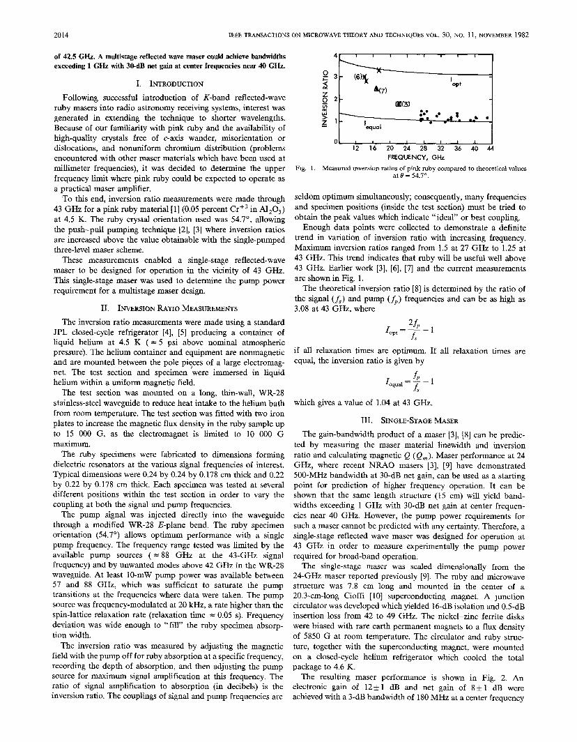
4r I I I 1 , I ! i 1
:3 - (6)\~
I
47)
opt
z02 -
m(3)
;, ~,:0. # ,**.
●
equal
o~16 20 24 28 32 36 40 44
FREQUENCY, GHz
Fig. 1, Measared reversion ratios of piak ruby compared to theoretical values
at b’ = 54.7°.
seldom optimum simultaneously; consequently, many frequencies
and specimen positions (inside tie test section) must be tried to
obtain the peak values which indicate “ideal” or best coupling.
Enough data points were collected to demonstrate a definite
trend in variation of inversion ratio with increasing frequency.
Maximum inversion ratios ranged from 1.5 at 27 GHz to 1.25 at
43 GHz. This trend indicates that ruby will be useful well above
43 GHz. Earlier work [3], [6], [7] and the current measurements
are shown in Fig. 1.
The theoretical inversion ratio [8] is determined by the ratio of
the signal (f,) and pump (~P) frequencies and can be as high as
3.08 at 43 GHz, where
ZfpIopt=—–l
f,
if all relaxation times are optimum. If all relaxation times are
equal, the inversion ratio is given by
Ifp_l
equal = —f,which gives a value of 1.04 at 43 GHz.
III. SINGLE-STAGE MASER
The gain-bandwidth product of a maser [3], [8] can be predic-
ted by measuring the maser material linewidth and inversion
ratio and calculating magnetic Q ( Q~ ). Maser performance at 24
GHz, where recent NRAO masers [3], [9] have demonstrated
500-MHz bandwidth at 30-dB net gain, can be used as a starting
point for prediction of higher frequency operation. It cars be
shown that the same length structure (15 cm) will yield band-
widths exceeding 1 GHz with 30-dB net gain at center frequen-
cies near 40 GHz. However, the pump power requirements for
such a maser cannot be predicted with any certainty. Therefore, a
single-stage reflected wave maser was designed for operation at
43 GHz in order to measure experimentally the pump power
required for broad-band operation.
The single-stage maser was scaled dimensionally from the
24-GHz maser reported previously [9]. The ruby and microwave
structure was 7.8 cm long and mounted in the center of a
20.3-cm-long Cioffi [10] superconducting magnet. A Junction
circulator was developed which yielded 16-dB isolation and 0.5-dB
insertion loss from 42 to 49 GHz. The nickel-zinc ferrite disks
were biased with rare earth permanent magnets to a flux density
of 5850 G at room temperature. The circulator and ruby struc-
ture, together with the superconducting magnet, were mounted
on a closed-cycle helium refrigerator which cooled the total
package to 4.6 K.
The resulting maser performance is shown in Fig. 2. An
electronic gain of 12 i 1 dB and net gain of 8 + 1 dB were
achieved with a 3-dB bandwidth of 180 MHz at a center frequency
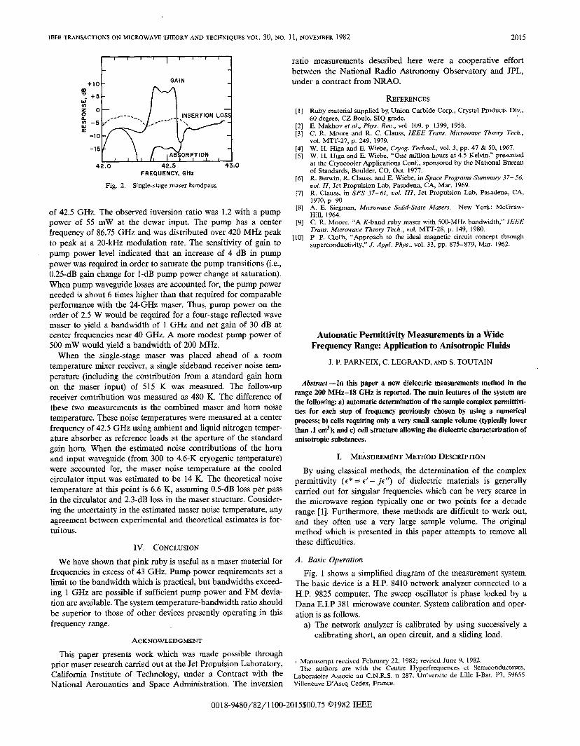
IEEE TRANSACTIONS ON MICROWAVE THEORY AND TECHNIQUES VOL. 30, NO. 11, NOVEMBER 1982 2015
1“’’’’’”4+10 -
GAIN
m‘. +5 -w020 —orl,wz
-10 -
-15
42.0 42.5 4380FREQUENCY, GHz
Fig. 2. Single-stage maser bandpass.
of 42.5 GHz. The observed inversion ratio was 1.2 with a pump
power of 55 mW at the dewar input. The pump has a center
frequency of 86.75 GHz and was distributed over 420 MHz peak
to peak at a 20-kHz modulation rate. The sensitivity of gain to
pump power level indicated that an increase of 4 dB in pump
power was required in order to saturate the pump transitions (i.e.,
0.25-dB gain change for l-dB pump power change at saturation).
When pump waveguide losses are accounted for, the pump power
needed is about 6 times higher than that required for comparable
performance with the 24-GHz maser. Thus, pump power on the
order of 2.5 W would be required for a four-stage reflected wave
maser to yield a bandwidth of 1 GHz and net gain of 30 dB at
center frequencies near 40 GHz. A more modest pump power of
500 mW would yield a bandwidth of 200 MHz.
When the single-stage maser was placed ahead of a room
temperature mixer receiver, a single sideband receiver noise tem-
perature (including the contribution from a standard gain horn
on the maser input) of 515 K was measured. The follow-up
receiver contribution was measured as 480 K. The difference of
these two measurements is the combined maser and horn noise
temperature. These noise temperatures were measured at a center
frequency of 42.5 GHz using ambient and liquid nitrogen temper-
ature absorber as reference loads at the aperture of the standard
gain horn. When the estimated noise contributions of the horn
and input waveguide (from 300 to 4.6-K cryogenic temperature)
were accounted for, the maser noise temperature at the cooled
circulator input was estimated to be 14 K. The theoretical noise
temperature at this point is 6.6 K, assuming 0.5-dB loss per pass
in the circulator and 2.3-dB loss in the maser structure. Consider-
ing the uncertainty in the estimated maser noise temperature, any
agreement between experimental and theoretical estimates is for-
tuitous.
IV. CONCLUSION
We have shown that pink ruby is useful as a maser material for
frequencies in excess of 43 GHz. Pump power requirements set a
limit to the bandwidth which is practical, but bandwidths exceed-
ing 1 GHz are possible if sufficient pump power and FM devia-
tion are available. The system temperature-bandwidth ratio should
be superior to those of other devices presently operating in this
frequency range.
ACKNOWLEDGMENT
This paper presents work which was made possible through
prior maser research carried out at the Jet Propulsion Laboratory,
California Institute of Technology, under a Contract with the
National Aeronautics and Space Administration. The inversion
ratio measurements described here were a cooperative effort
between the National Radio Astronomy Observatory and JPL,
under a contract from NRAO.
[1]
[2][3]
[4][5]
[6]
[7]
[8]
[9]
[10]
IbFE~NCEs
Ruby materkd supplied by Union Carbide Corp., Crystaf Products Div.,60 degree, CZ Boule, SIQ grade.E. Makhov er al., Phys. Rev., vol 109, p 1399, 1958.
C, R. Moore and R. C. Clauss, IEEE Trans. Microwave Theory Tech.,
vol. MTT-27, p. 249, 1979.W. H. Higa and E. Wiebe, Cryog. Techno[., vol. 3, pp. 47 & 50, 1967.W, H. Fhga and E. Wiebe, “One million hours at 4.5 Kelvin,” presented
at the Cryocooler Applications Conf., sponsored by the National Bureau
of Standards, Boulder, CO, Oct. 1977.
R. Berwirr, R. Clauss, and E. Wiebe, in Space Programs Summary 37-56,
vol. 11, Jet Propulsion Lab, Pasadena, CA, Mar. 1969.
R. Clauss, in SPS 37-61, vol. 111, Jet Propulsion Lab, Pasadena, CA,
1970, p 90.
A, E. Siegmarr, Mtcrowave Solid-State Masers. New York: McGraw-
Hill, 1964.
C. R. Moore, “A K-band ruby maser with 500-MH2 bandwidth,” IEEE
Trans. M~crowaoe Theory Tech., vol. MTT-28, p. 149, 1980.
P P. Cloffl, “Approach to the ideal magnetic circuit concept through
superconductivity,” J. Appl. Phys., vol. 33, pp. 875-879, Mar. 1962.
Automatic Permittivity Measurements in a Wide
Frequency Range Application to Anisotropic Fluids
J. P. PARNEIX, C. LEGRAND, AND S. TOUTAIN
Abstract —In this paper a new dielectric measurements method in the
range 200 MHz- 18 GHz is reported. The main features of the system are
the following a) automatic determination of the sample complex permittivi-
ties for each step of frequency previously chosen by using a numerical
proeesy b) cells requiring only a very smafl sample volume (typically lower
than. 1 c~~ aud c) cell strnctnre allowing the dielectric characterization of
anisotropic substances.
1. NCsAsuNmrvr METHOD DESCRIPTION
By using classical methods, the determination of the complex
permittivity (C*= c’ – j(”) of dielectric materials is generally
carried out for singular frequencies which can be very scarce in
the microwave region typically one or two points for a decade
range [1]. Furthermore, these methods are difficult to work out,
and they often use a very large sample volume. The original
method which is presented in this paper attempts to remove all
these difficulties.
A. Basic Operation
Fig. 1 shows a simplified diagram of the measurement system.
The basic device is a H.P. 8410 network analyzer connected to a
H.P. 9825 computer. The sweep oscillator is phase locked by a
Dana E.I.P 381 microwave counter. System calibration and oper-
ation is as follows.
a) The network analyzer is calibrated by using successively a
calibrating short, an open circuit, and a sliding load.
Mamrscnpt received February 22, 1982; revised June 9, 1982.
The authors are with the Centre Hyperfrequences et Sernrconducteurs,
Laboratoire Associe au C.N.R.S. n 287, University de Line I-Bat. P3, 59655
Villeneuve D’Ascq Cedex, France.
0018-9480/82/1 100-2015$00.75 ~1 982 IEEE