expendable-mold casting process · pdf fileexpendable-mold casting process ... •high...
TRANSCRIPT
Veljko Samardzic ME-215 Engineering Materials and Processes
Expendable-Mold Casting Process
Chapter 12

Veljko Samardzic ME-215 Engineering Materials and Processes
12.1 Introduction
• Factors to consider for castings
– Desired dimensional accuracy
– Surface quality
– Number of castings
– Type of pattern and core box needed
– Cost of required mold or die
– Restrictions due to the selected material
• Three categories of molds
– Single-use molds with multiple-use patterns
– Single-use molds with single-use patterns
– Multiple-use molds

Veljko Samardzic ME-215 Engineering Materials and Processes
12.2 Sand Casting
• Sand casting is the most common and
versatile form of casting
– Granular material is mixed with clay and water
– Packed around a pattern
• Gravity flow is the most common method of
inserting the liquid metal into the mold
• Metal is allowed to solidify and then the
mold is removed

Veljko Samardzic ME-215 Engineering Materials and Processes
Sand Casting
Figure 12-1 Sequential
steps in making a sand
casting. a) A pattern board
is placed between the
bottom (drag) and top
(cope) halves of a flask,
with the bottom side up. b)
Sand is then packed into
the bottom or drag half of
the mold. c) A bottom board
is positioned on top of the
packed sand, and the mold
is turned over, showing the
top (cope) half of pattern
with sprue and riser pins in
place. d) The upper or cope
half of the mold is then
packed with sand.
Veljko Samardzic ME-215 Engineering Materials and Processes
Sand Casting
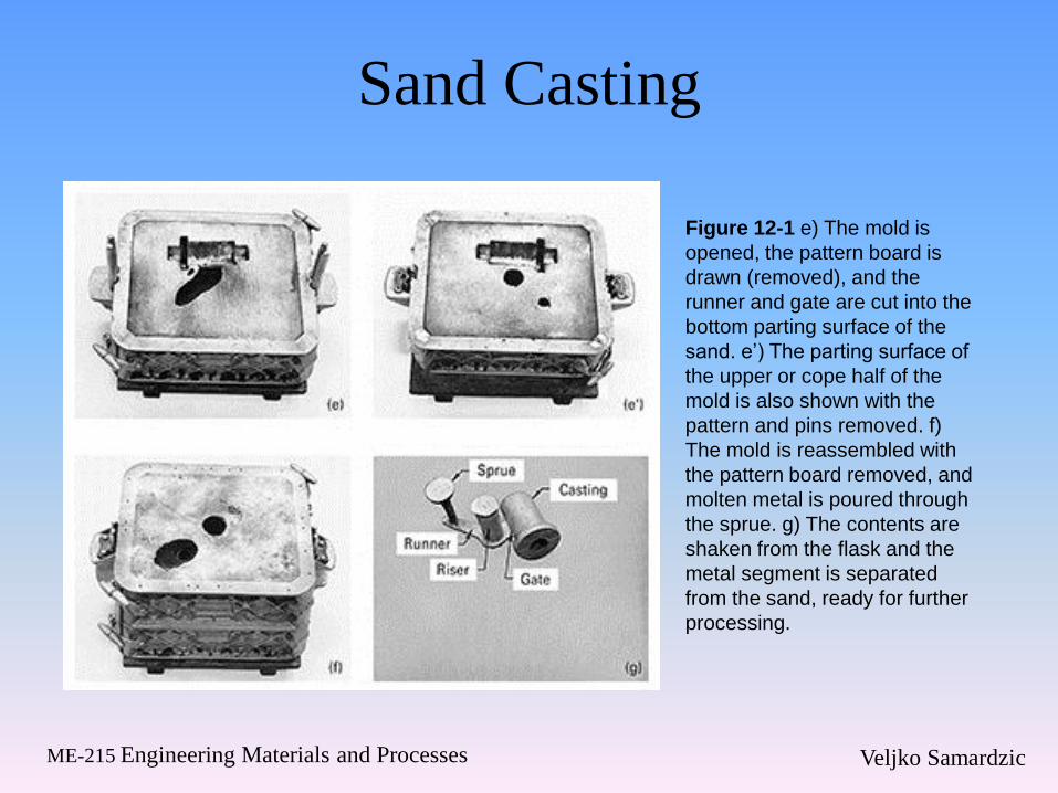
Figure 12-1 e) The mold is
opened, the pattern board is
drawn (removed), and the
runner and gate are cut into the
bottom parting surface of the
sand. e’) The parting surface of
the upper or cope half of the
mold is also shown with the
pattern and pins removed. f)
The mold is reassembled with
the pattern board removed, and
molten metal is poured through
the sprue. g) The contents are
shaken from the flask and the
metal segment is separated
from the sand, ready for further
processing.
Veljko Samardzic ME-215 Engineering Materials and Processes
Patterns and Pattern Materials
• First step in casting is to design and construct the
pattern
• Pattern selection is determined by the number of
castings, size and shape of castings, desired
dimensional precision, and molding process
• Pattern materials
– Wood patterns are relatively cheap, but not
dimensionally stable
– Metal patterns are expensive, but more stable and
durable
– Hard plastics may also be used

Veljko Samardzic ME-215 Engineering Materials and Processes
Types of Patterns
• The type of pattern is selected based on the
number of castings and the complexity of
the part
• One-piece or solid patterns are used when
the shape is relatively simple and the
number of castings is small
• Split patterns are used for moderate
quantities
– Pattern is divided into two segments
Veljko Samardzic ME-215 Engineering Materials and Processes
Types of Patterns
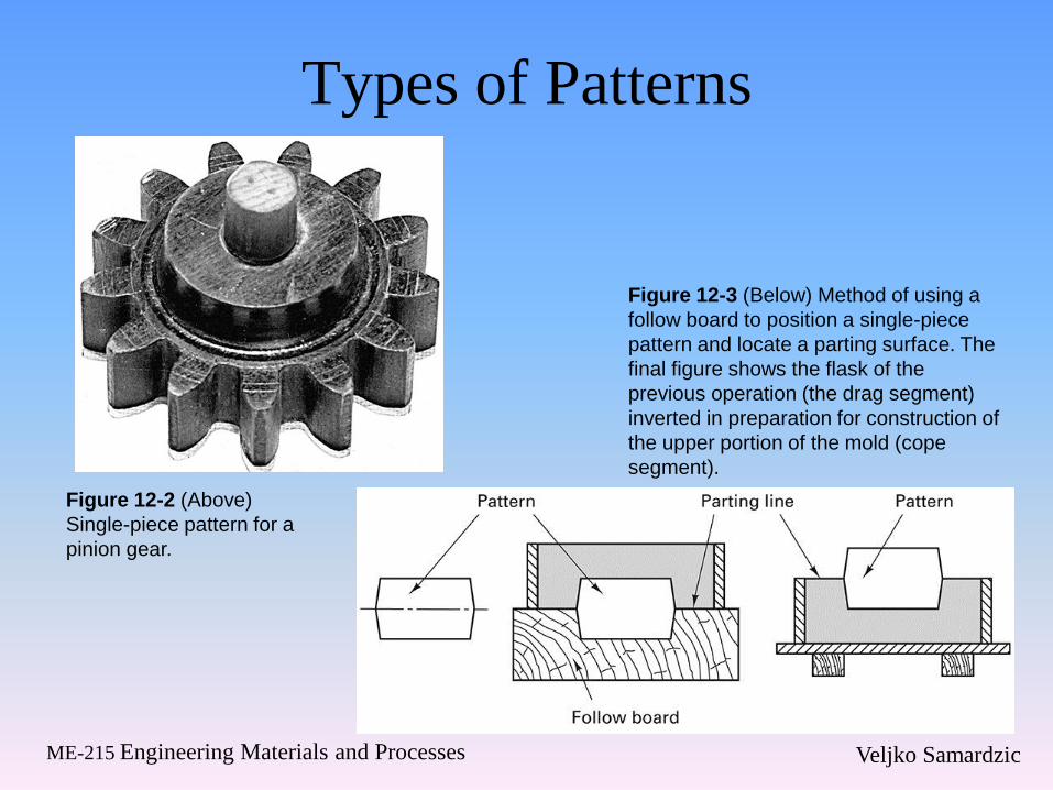
Figure 12-3 (Below) Method of using a
follow board to position a single-piece
pattern and locate a parting surface. The
final figure shows the flask of the
previous operation (the drag segment)
inverted in preparation for construction of
the upper portion of the mold (cope
segment).
Figure 12-2 (Above)
Single-piece pattern for a
pinion gear.
Veljko Samardzic ME-215 Engineering Materials and Processes
Types of Patterns
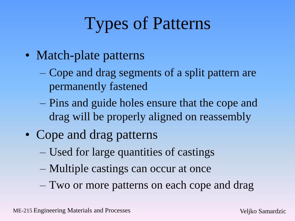
• Match-plate patterns
– Cope and drag segments of a split pattern are
permanently fastened
– Pins and guide holes ensure that the cope and
drag will be properly aligned on reassembly
• Cope and drag patterns
– Used for large quantities of castings
– Multiple castings can occur at once
– Two or more patterns on each cope and drag

Veljko Samardzic ME-215 Engineering Materials and Processes
Types of Patterns
Figure 12-4 Split pattern, showing the two
sections together and separated. The light-
colored portions are core prints.
Figure 12-5 Match-plate pattern used to
produce two identical parts in a single flask.
(Left) Cope side; (right) drag side. (Note: The
views are opposite sides of a single-pattern
board.
Veljko Samardzic ME-215 Engineering Materials and Processes
Cope and Drag Patterns
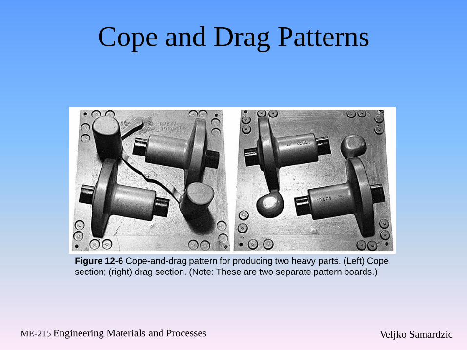
Figure 12-6 Cope-and-drag pattern for producing two heavy parts. (Left) Cope
section; (right) drag section. (Note: These are two separate pattern boards.)
Veljko Samardzic ME-215 Engineering Materials and Processes
Sands and Sand Conditioning
• Four requirements of sand used in casting
– Refractoriness-ability withstand high temperatures
– Cohesiveness-ability to retain shape
– Permeability-ability of a gases to escape through the sand
– Collapsibility-ability to accommodate shrinkage and part removal
• Size of sand particles, amount of bonding agent, moisture content, and additives are selected to obtain sufficient requirements
Veljko Samardzic ME-215 Engineering Materials and Processes
Processing of Sand
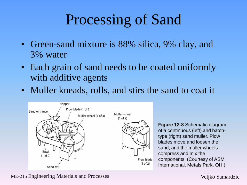
• Green-sand mixture is 88% silica, 9% clay, and 3% water
• Each grain of sand needs to be coated uniformly with additive agents
• Muller kneads, rolls, and stirs the sand to coat it
Figure 12-8 Schematic diagram
of a continuous (left) and batch-
type (right) sand muller. Plow
blades move and loosen the
sand, and the muller wheels
compress and mix the
components. (Courtesy of ASM
International. Metals Park, OH.)
Veljko Samardzic ME-215 Engineering Materials and Processes
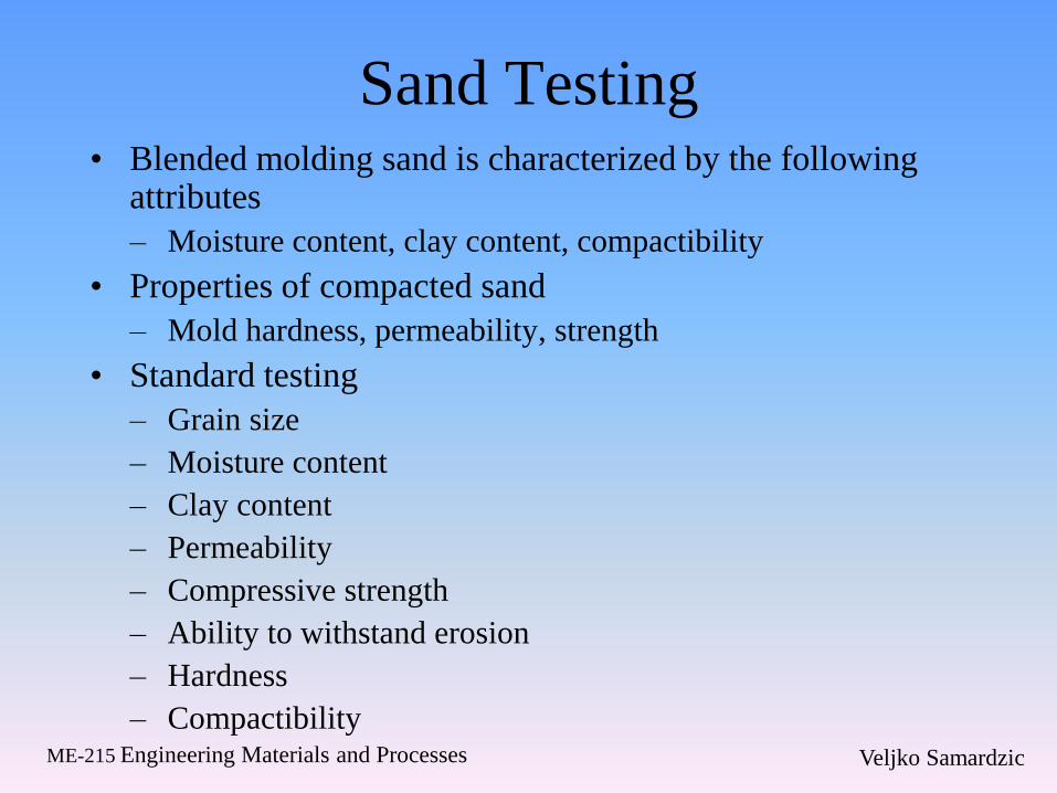
Sand Testing • Blended molding sand is characterized by the following
attributes
– Moisture content, clay content, compactibility
• Properties of compacted sand
– Mold hardness, permeability, strength
• Standard testing
– Grain size
– Moisture content
– Clay content
– Permeability
– Compressive strength
– Ability to withstand erosion
– Hardness
– Compactibility

Veljko Samardzic ME-215 Engineering Materials and Processes
Sand Testing Equipment
Figure 12-9 Schematic of a permeability tester in
operation. A standard sample in a metal sleeve is sealed
by an O-ring onto the top of the unit while air is passed
through the sand. (Courtesy of Dietert Foundry Testing
Equipment Inc, Detroit, MI)
Figure 12-10 Sand mold hardness
tester. (Courtesy of Dietert Foundry
Testing Equipment Inc., Detroit, MI)
Veljko Samardzic ME-215 Engineering Materials and Processes
Sand Properties and Sand-Related
Defects
• Silica sand
– Cheap and lightweight but undergoes a phase
transformation and volumetric expansion when
it is heated to 585°C
• Castings with large, flat surfaces are prone
to sand expansion defects
• Trapped or dissolved gases can cause gas-
related voids or blows
Veljko Samardzic ME-215 Engineering Materials and Processes
Sand Properties
• Penetration occurs when the sand grains
become embedded in the surface of the
casting
• Hot tears or crack occur in metals with large
amounts of solidification shrinkage
– Tensile stresses develop while the metal is still
partially liquid and if these stresses do not go
away, cracking can occur.
Veljko Samardzic ME-215 Engineering Materials and Processes
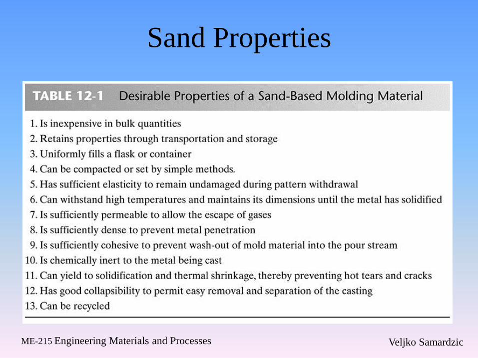
Sand Properties
Veljko Samardzic ME-215 Engineering Materials and Processes
The Making of Sand Molds
• Hand ramming is the method of packing
sand to produce a sand mold
– Used when few castings are to be made
– Slow, labor intensive
– Nonuniform compaction
• Molding machines
– Reduce the labor and required skill
– Castings with good dimensional accuracy and
consistency
Veljko Samardzic ME-215 Engineering Materials and Processes
The Making of Sand Molds
• Molds begin with a pattern and a flask
• Mixed sand is packed in the flask
– Sand slinger uses rotation to fling sand against the pattern
– Jolting is a process in which sand is placed over the flask and pattern and they are all lifted and dropped to compact the sand
– Squeezing machines use air and a diaphragm
• For match plate molding, a combination of jolting and squeezing is used
Veljko Samardzic ME-215 Engineering Materials and Processes
Methods of Compacting Sand
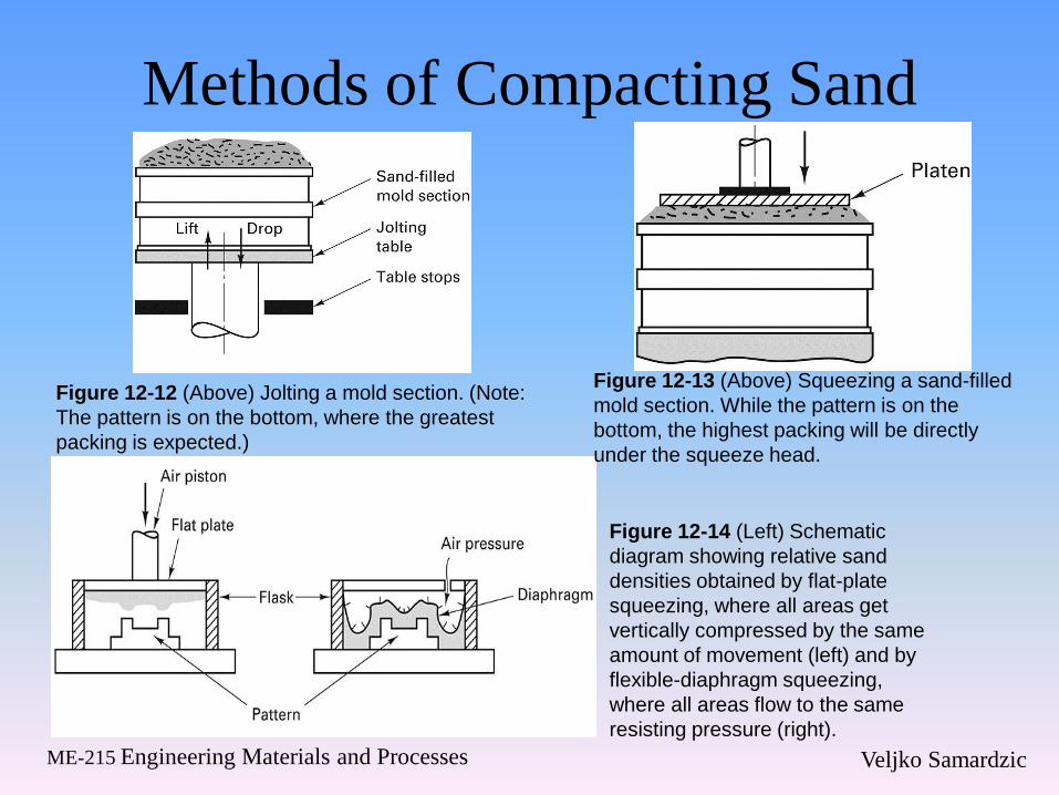
Figure 12-12 (Above) Jolting a mold section. (Note:
The pattern is on the bottom, where the greatest
packing is expected.)
Figure 12-13 (Above) Squeezing a sand-filled
mold section. While the pattern is on the
bottom, the highest packing will be directly
under the squeeze head.
Figure 12-14 (Left) Schematic
diagram showing relative sand
densities obtained by flat-plate
squeezing, where all areas get
vertically compressed by the same
amount of movement (left) and by
flexible-diaphragm squeezing,
where all areas flow to the same
resisting pressure (right).
Veljko Samardzic ME-215 Engineering Materials and Processes
Alternative Molding Methods
• Stack molding
– Molds containing a cope impression on the bottom and a drag impression on the top are stacked on top of one another vertically
– Common vertical sprue
• Large molds
– Large flasks can be placed directly on the foundry floor
– Sand slingers may be used to pack the sand
– Pneumatic rammers may be used
Veljko Samardzic ME-215 Engineering Materials and Processes
Green-Sand, Dry-Sand, and Skin-
Dried Molds
• Green-sand casting
– Process for both ferrous and nonferrous metals
– Sand is blended with clay, water, and additives
– Molds are filled by a gravity feed
– Low tooling costs
– Least expensive
• Design limitations
– Rough surface finish
– Poor dimensional accuracy
– Low strength
Veljko Samardzic ME-215 Engineering Materials and Processes
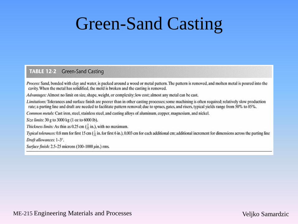
Green-Sand Casting
Veljko Samardzic ME-215 Engineering Materials and Processes
Dry-Sand
• Dry-sand molds are durable
– Long storage life
– Long time required for drying
• Skin-dried molds
– Dries only the sand next to the mold cavity
– Torches may be used to dry the sand
– Used for large steel parts
– Binders may be added to enhance the strength
of the skin-dried layer

Veljko Samardzic ME-215 Engineering Materials and Processes
Cast Parts
Figure 12-17 A variety of sand cast aluminum parts. (Courtesy of
Bodine Aluminum Inc., St. Louis, MO)
Veljko Samardzic ME-215 Engineering Materials and Processes
Sodium Silicate-CO2 Molding
• Molds and cores can receive strength from
the addition of 3-6% sodium silicate
• Remains soft and moldable until it is
exposed to CO2
• Hardened sands have poor collapsibility
– Shakeout and core removal is difficult
• Heating makes the mold stronger
Veljko Samardzic ME-215 Engineering Materials and Processes
No-Bake, Air-Set, or Chemically
Bonded Sands
• Organic and inorganic resin binders can be
mixed with the sand before the molding
operation
– Curing reactions begin immediately
• Cost of no-bake molding is about 20-30%
more than green-sand molding
• High dimensional precision and good
surface finish

Veljko Samardzic ME-215 Engineering Materials and Processes
No-Bake Sands
• No-bake sand can be compacted by light vibrations
– Wood, plastic, fiberglass, or Styrofoam can be used as patterns
• System selections are based on the metal being poured, cure time desired, complexity and thickness of the casting, and the possibility of sand reclamation
• Good hot strength
• High resistance to mold-related casting defects
• Mold decomposes after the metal has been poured providing good shakeout
Veljko Samardzic ME-215 Engineering Materials and Processes
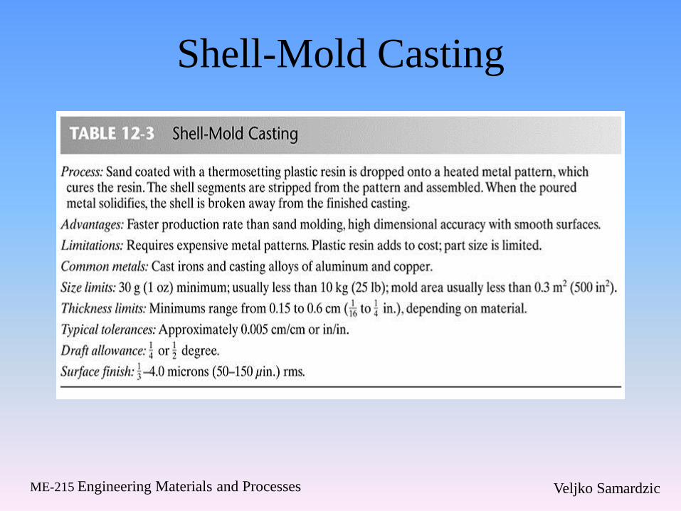
Shell Molding
• Basic steps
– Individual grains are sand are precoated with a thin layer of thermosetting resin
• Heat from the pattern partially cures a layer of material
– Pattern and sand mixture are inverted and only the layer of partially cured material remains
– The pattern with the shell is placed in an oven and the curing process is completed
– Hardened shell is stripped from the pattern
– Shells are clamped or glued together with a thermoset adhesive
– Shell molds are placed in a pouring jacked and surrounded by sand, gravel, etc. for extra support
Veljko Samardzic ME-215 Engineering Materials and Processes
Shell Molding
• Cost of a metal pattern is often high
– Design must include the gate and the runner
– Expensive binder is required
– Amount of required material is less
– High productivity, low labor costs, smooth
surfaces, high level of precision
Veljko Samardzic ME-215 Engineering Materials and Processes
Dump-Box Shell Molding
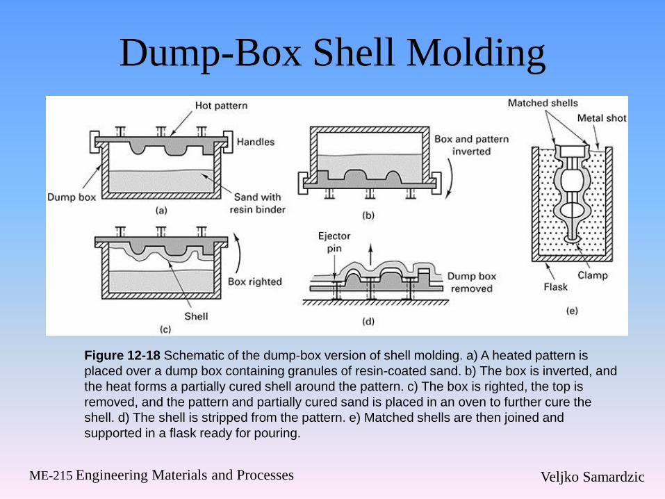
Figure 12-18 Schematic of the dump-box version of shell molding. a) A heated pattern is
placed over a dump box containing granules of resin-coated sand. b) The box is inverted, and
the heat forms a partially cured shell around the pattern. c) The box is righted, the top is
removed, and the pattern and partially cured sand is placed in an oven to further cure the
shell. d) The shell is stripped from the pattern. e) Matched shells are then joined and
supported in a flask ready for pouring.
Veljko Samardzic ME-215 Engineering Materials and Processes
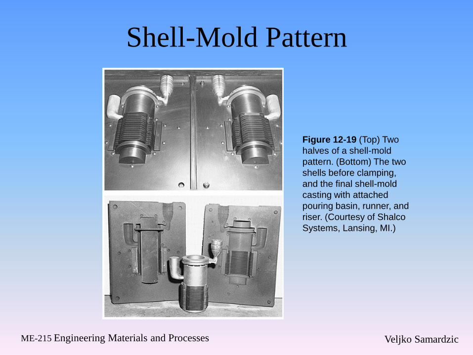
Shell-Mold Pattern
Figure 12-19 (Top) Two
halves of a shell-mold
pattern. (Bottom) The two
shells before clamping,
and the final shell-mold
casting with attached
pouring basin, runner, and
riser. (Courtesy of Shalco
Systems, Lansing, MI.)
Veljko Samardzic ME-215 Engineering Materials and Processes
Shell-Mold Casting
Veljko Samardzic ME-215 Engineering Materials and Processes
Other Sand-Based Molding
Methods • V-process or vacuum molding
– Vacuum serves as the sand binder
– Applied within the pattern, drawing the sheet
tight to its surface
– Flask is filled with vibrated dry, unbonded sand
– Compacts the sand and gives the sand its
necessary strength and hardness
– When the vacuum is released, the pattern is
withdrawn
Veljko Samardzic ME-215 Engineering Materials and Processes
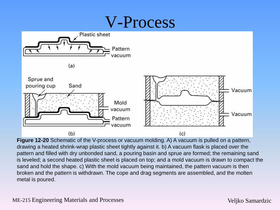
V-Process
Figure 12-20 Schematic of the V-process or vacuum molding. A) A vacuum is pulled on a pattern,
drawing a heated shrink-wrap plastic sheet tightly against it. b) A vacuum flask is placed over the
pattern and filled with dry unbonded sand, a pouring basin and sprue are formed; the remaining sand
is leveled; a second heated plastic sheet is placed on top; and a mold vacuum is drawn to compact the
sand and hold the shape. c) With the mold vacuum being maintained, the pattern vacuum is then
broken and the pattern is withdrawn. The cope and drag segments are assembled, and the molten
metal is poured.
Veljko Samardzic ME-215 Engineering Materials and Processes
Advantages and Disadvantages of the
V-Process • Advantages
– Absence of moisture-related defects
– Binder cost is eliminated
– Sand is completely reusable
– Finer sands can be used
– Better surface finish
– No fumes generated during the pouring operation
– Exceptional shakeout characteristics
• Disadvantages – Relatively slow process
– Used primarily for production of prototypes
– Low to medium volume parts
– More than 10 but less than 50,000

Veljko Samardzic ME-215 Engineering Materials and Processes
Eff-set Process
• Wet sand with enough clay to prevent mold
collapse
• Pattern is removed
– Surface of the mold is sprayed with liquid
nitrogen
• Ice that forms serves as a binder
• Molten metal is poured into the mold
• Low binder cost and excellent shakeout

Veljko Samardzic ME-215 Engineering Materials and Processes
12.3 Cores and Core Making
• Complex internal cavities can be produced
with cores
• Cores can be used to improve casting design
• Cores may have relatively low strength
• If long cores are used, machining may need
to be done afterwards
• Green sand cores are not an option for more
complex shapes
Veljko Samardzic ME-215 Engineering Materials and Processes
Dry-Sand Cores
• Produced separate from the remainder of the mold
• Inserted into core prints that hold the cores in position
• Dump-core box
– Sand is packed into the mold cavity
– Sand is baked or hardened
• Single-piece cores
– Two-halves of a core box are clamped together
Veljko Samardzic ME-215 Engineering Materials and Processes
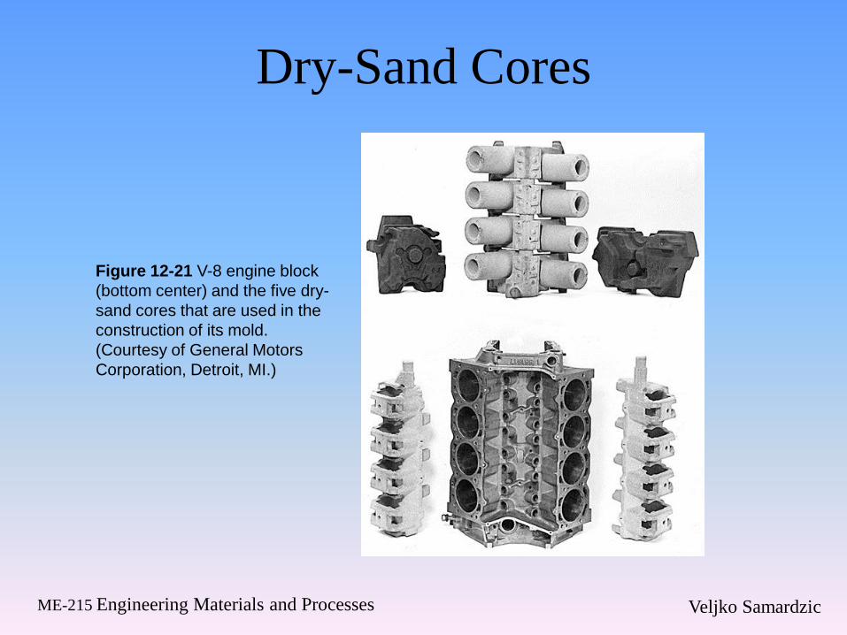
Dry-Sand Cores
Figure 12-21 V-8 engine block
(bottom center) and the five dry-
sand cores that are used in the
construction of its mold.
(Courtesy of General Motors
Corporation, Detroit, MI.)
Veljko Samardzic ME-215 Engineering Materials and Processes
Additional Core Methods
• Core-oil process
– Sand is blended with oil to develop strength
– Wet sand is blown or rammed into a simple
core box
• Hot-box method
– Sand is blended with a thermosetting binder
• Cold-box process
– Binder coated sand is packed and then sealed
– Gas or vaporized catalyst polymerizes the resin

Veljko Samardzic ME-215 Engineering Materials and Processes
Additional Core Methods
Figure 12-23 (Right) Upper Right; A
dump-type core box; (bottom) core
halves for baking; and (upper left) a
completed core made by gluing two
opposing halves together.
Figure 12-22 (Left) Four methods of making a
hole in a cast pulley. Three involve the use of
a core.

Veljko Samardzic ME-215 Engineering Materials and Processes
Additional Core Considerations
• Air-set or no-bake sands may be used
– Eliminate gassing operations
– Reactive organic resin and a curing catalyst
• Shell-molding
– Core making alternative
– Produces hollow cores with excellent strength
• Selecting the proper core method is based on the
following considerations
– Production quantity, production rate, required precision,
required surface finish, metal being poured
Veljko Samardzic ME-215 Engineering Materials and Processes
Casting Core Characteristics
• Sufficient strength before hardening
• Sufficient hardness and strength after
hardening
• Smooth surface
• Minimum generation of gases
• Adequate permeability
• Adequate refractoriness
• Collapsibility
Veljko Samardzic ME-215 Engineering Materials and Processes
Techniques to Enhance Core
Properties
• Addition of internal wires or rods
• Vent holes
• Cores can be connected to the outer surfaces
of the mold cavity
– Core prints
• Chaplets- small metal supports that are
placed between the cores and the mold
cavity surfaces and become integral to the
final casting
Veljko Samardzic ME-215 Engineering Materials and Processes
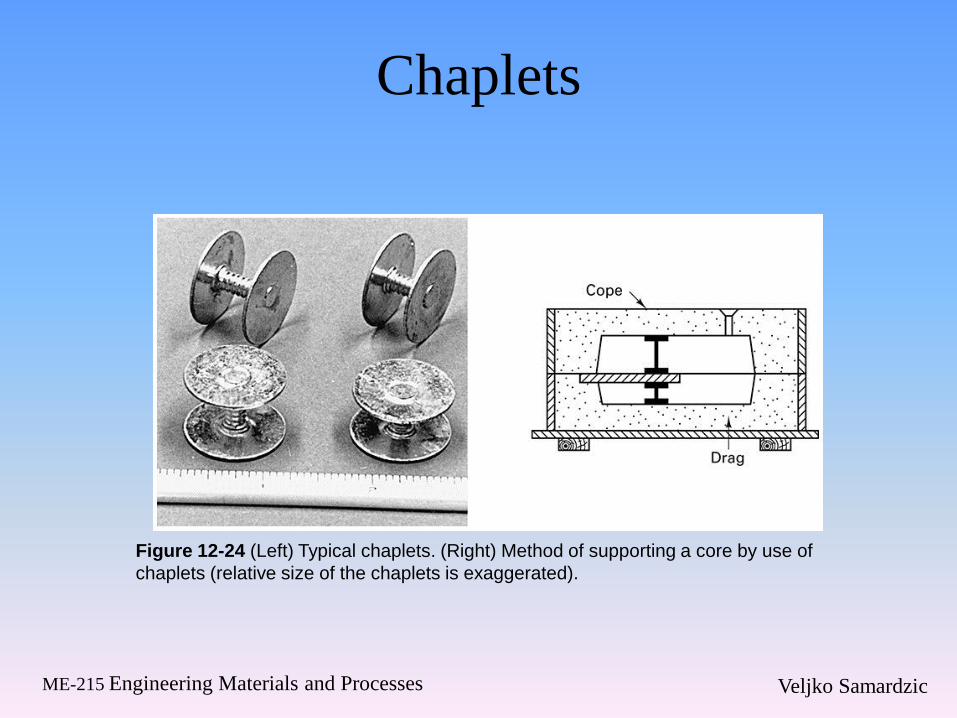
Chaplets
Figure 12-24 (Left) Typical chaplets. (Right) Method of supporting a core by use of
chaplets (relative size of the chaplets is exaggerated).
Veljko Samardzic ME-215 Engineering Materials and Processes
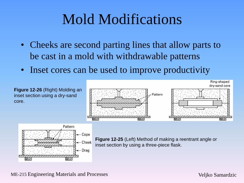
Mold Modifications
• Cheeks are second parting lines that allow parts to
be cast in a mold with withdrawable patterns
• Inset cores can be used to improve productivity
Figure 12-25 (Left) Method of making a reentrant angle or
inset section by using a three-piece flask.
Figure 12-26 (Right) Molding an
inset section using a dry-sand
core.
Veljko Samardzic ME-215 Engineering Materials and Processes
12.4 Other Expendable-Mold Processes
with Multiple-Use Patterns
• Plaster mold casting
– Mold material is made out of plaster of paris
– Slurry is poured over a metal pattern
– Improved surface finish and dimensional
accuracy
– Limited to the lower-melting-temperature
nonferrous alloys
• Antioch process
– Variation of plaster mold casting
– 50% plaster, 50% sand
Veljko Samardzic ME-215 Engineering Materials and Processes
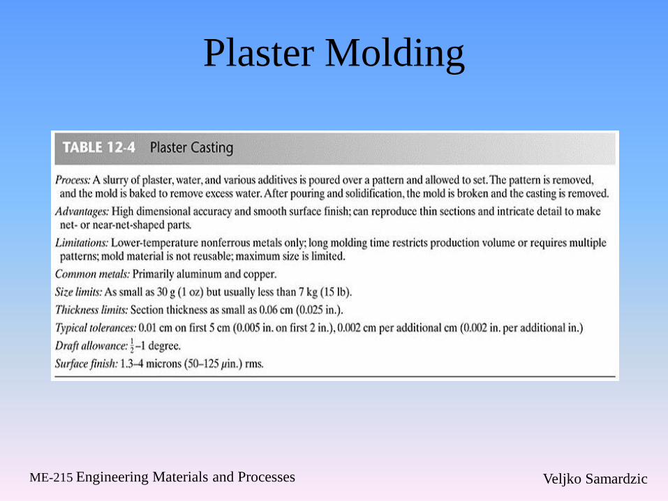
Plaster Molding

Veljko Samardzic ME-215 Engineering Materials and Processes
Ceramic Mold Casting
• Mold is made from ceramic material
• Ceramics can withstand higher temperatures
• Greater mold cost than other casting
methods
• Shaw process
– Reusable pattern inside a slightly tapered flask
– Mixture sets to a rubbery state that allows the
part and flask to be removed
– Mold surface is then ignited with a torch

Veljko Samardzic ME-215 Engineering Materials and Processes
Ceramic Mold Casting
Figure 12-27 Group of intricate
cutters produced by ceramic mold
casting. (Courtesy of Avnet Shaw
Division of Avnet, Inc., Phoenix, AZ)
Veljko Samardzic ME-215 Engineering Materials and Processes
Other Casting Methods
• Expendable graphite molds
– Some metals are difficult to cast
• Titanium
• Reacts with many common mold materials
– Powdered graphite can be combined with additives and
compacted around a pattern
– Mold is broken to remove the product
• Rubber-mold casting
– Artificial elastomers can be compounded in liquid form
and poured over the pattern to produce a semirigid mold
– Limited to small castings and low-melting-point
materials
Veljko Samardzic ME-215 Engineering Materials and Processes
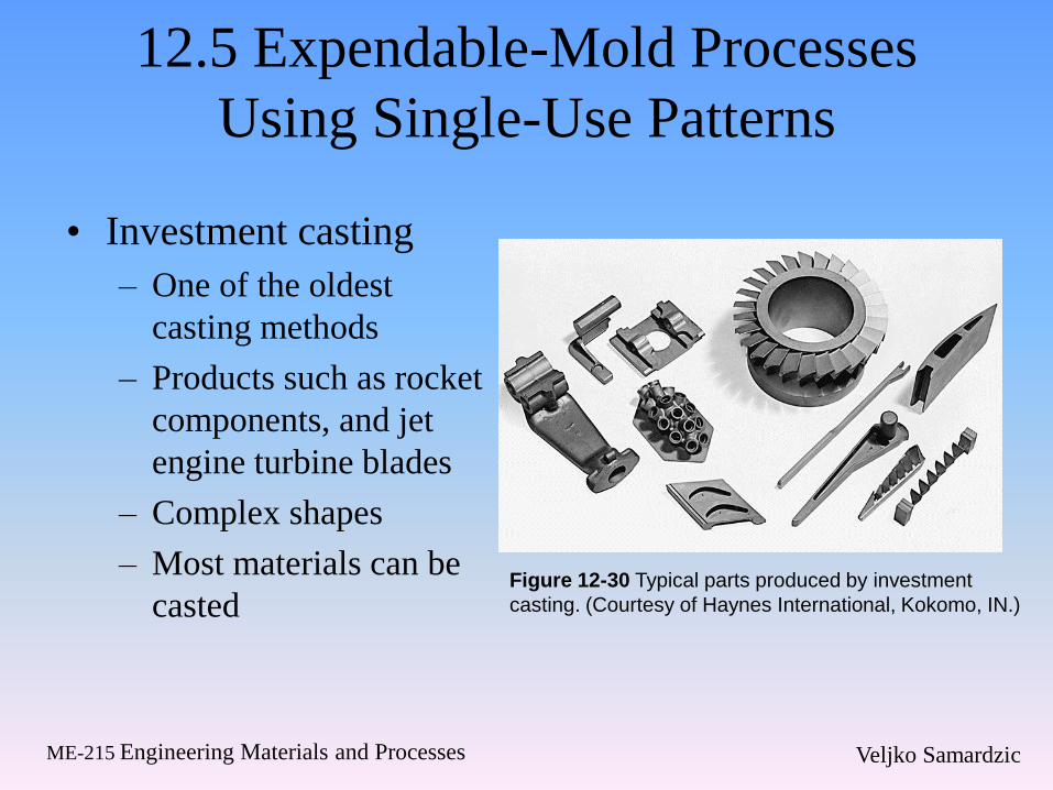
12.5 Expendable-Mold Processes
Using Single-Use Patterns
• Investment casting
– One of the oldest
casting methods
– Products such as rocket
components, and jet
engine turbine blades
– Complex shapes
– Most materials can be
casted Figure 12-30 Typical parts produced by investment
casting. (Courtesy of Haynes International, Kokomo, IN.)
Veljko Samardzic ME-215 Engineering Materials and Processes
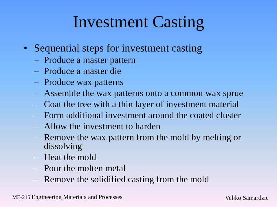
Investment Casting
• Sequential steps for investment casting – Produce a master pattern
– Produce a master die
– Produce wax patterns
– Assemble the wax patterns onto a common wax sprue
– Coat the tree with a thin layer of investment material
– Form additional investment around the coated cluster
– Allow the investment to harden
– Remove the wax pattern from the mold by melting or dissolving
– Heat the mold
– Pour the molten metal
– Remove the solidified casting from the mold
Veljko Samardzic ME-215 Engineering Materials and Processes
Advantages and Disadvantages of
Investment Casting
• Disadvantage
– Complex process
– Can be costly
• Advantage
– Complex shapes can be cast
– Thin sections can be cast
– Machining can be eliminated or reduced
Veljko Samardzic ME-215 Engineering Materials and Processes
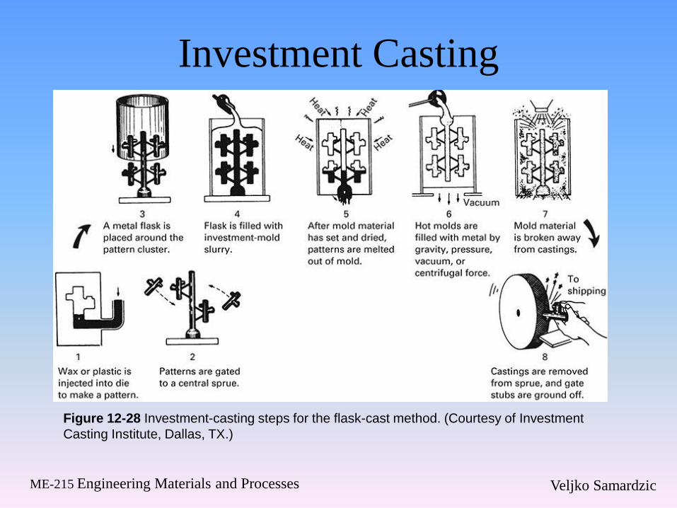
Investment Casting
Figure 12-28 Investment-casting steps for the flask-cast method. (Courtesy of Investment
Casting Institute, Dallas, TX.)
Veljko Samardzic ME-215 Engineering Materials and Processes
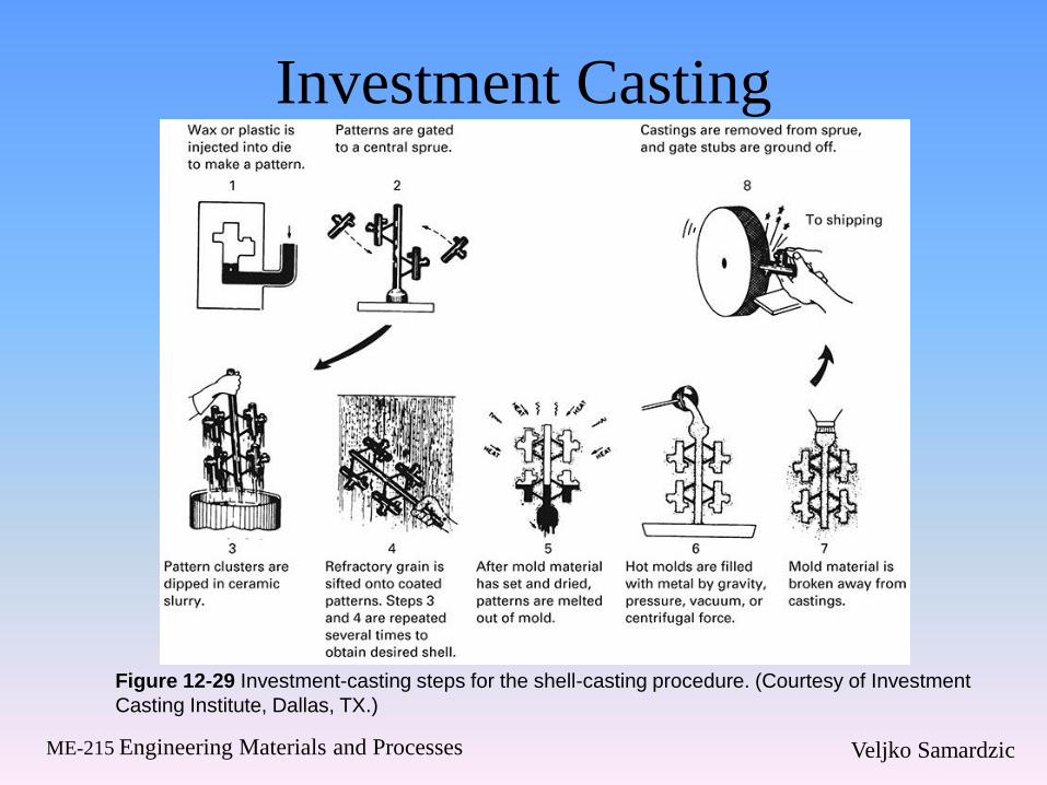
Investment Casting
Figure 12-29 Investment-casting steps for the shell-casting procedure. (Courtesy of Investment
Casting Institute, Dallas, TX.)

Veljko Samardzic ME-215 Engineering Materials and Processes
Investment Casting

Veljko Samardzic ME-215 Engineering Materials and Processes
Counter-Gravity Investment
Casting • Pouring process is upside down
• Vacuum is used within the chamber
– Draws metal up through the central sprue and into the mold
• Free of slag and dross
• Low level of inclusions
• Little turbulence
• Improved machinability
• Mechanical properties approach those of wrought material
• Simpler gating systems
• Lower pouring temperatures
• Improved grain structure and better surface finish

Veljko Samardzic ME-215 Engineering Materials and Processes
Evaporative Pattern (Full-Mold and
Lost-Foam) Casting
• Reusable patterns can complicate
withdrawal
– May mandate design modifications
• Evaporative pattern processes
– Pattern is made of polystyrene or
polymethylmethacrylate
• Pattern remains in the mold until the molten metal
melts away the pattern
• If small quantities are required, patterns may be cut
by hand
• Material is lightweight
Veljko Samardzic ME-215 Engineering Materials and Processes
Evaporative Patterns
• Metal mold or die is used to mass-produce
the evaporative patterns
• For multiple and complex shapes, patterns
can be divided into segments or slices
– Assembled by hot-melt gluing
• Full-mold process
– Green sand is compacted around the pattern and
gating system
Veljko Samardzic ME-215 Engineering Materials and Processes
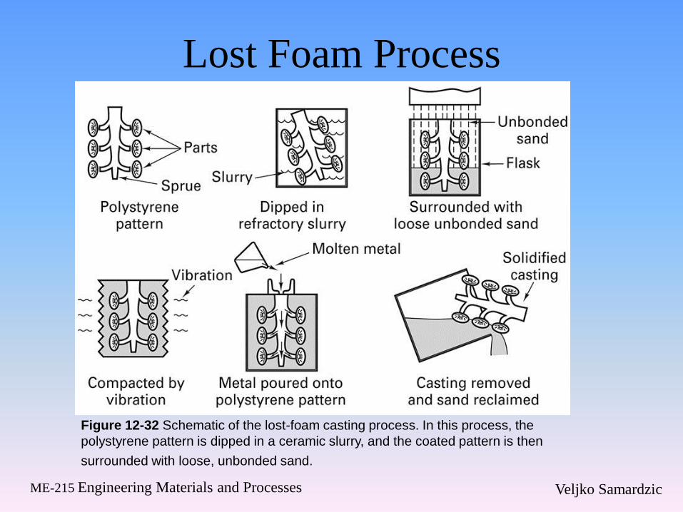
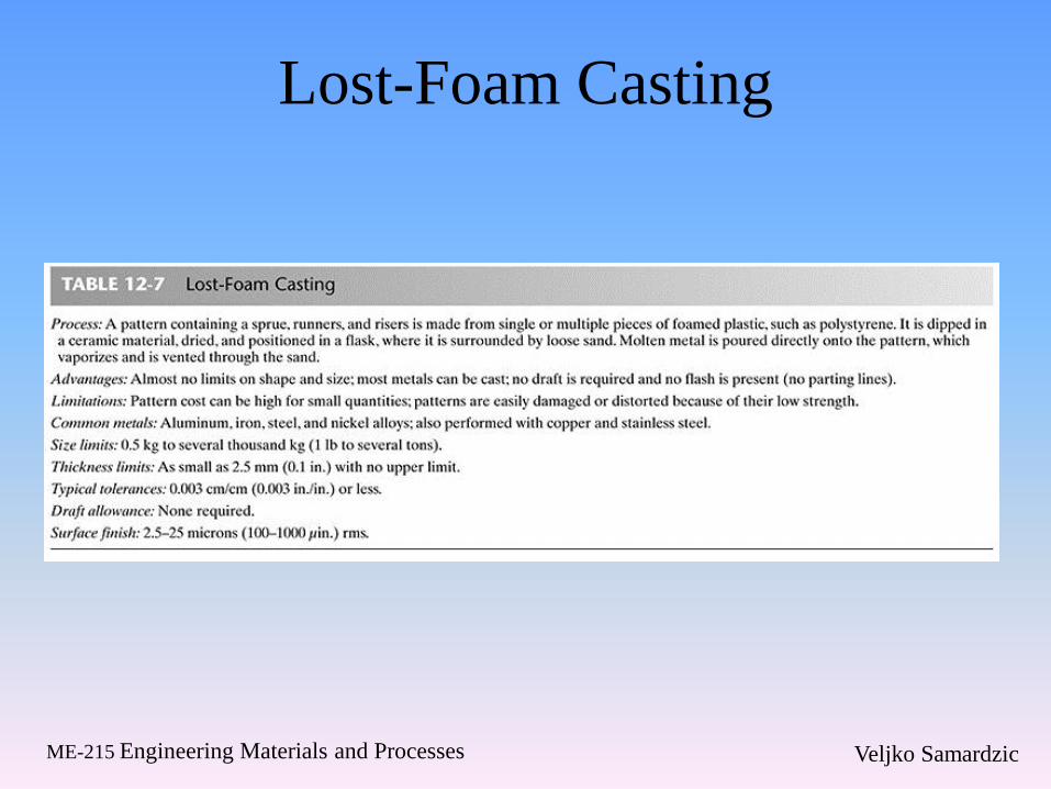
Lost Foam Process
Figure 12-32 Schematic of the lost-foam casting process. In this process, the
polystyrene pattern is dipped in a ceramic slurry, and the coated pattern is then
surrounded with loose, unbonded sand.
Veljko Samardzic ME-215 Engineering Materials and Processes
Advantages of the Full-Mold and
Lost-Foam Process
• Sand can be reused
• Castings of almost any size
• Both ferrous and nonferrous metals
• No draft is required
• Complex patterns
• Smooth surface finish
• Absence of parting lines
Veljko Samardzic ME-215 Engineering Materials and Processes
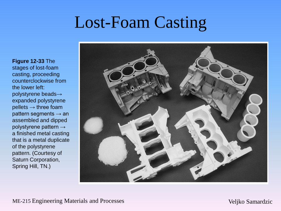
Lost-Foam Casting
Figure 12-33 The
stages of lost-foam
casting, proceeding
counterclockwise from
the lower left:
polystyrene beads→
expanded polystyrene
pellets → three foam
pattern segments → an
assembled and dipped
polystyrene pattern →
a finished metal casting
that is a metal duplicate
of the polystyrene
pattern. (Courtesy of
Saturn Corporation,
Spring Hill, TN.)
Veljko Samardzic ME-215 Engineering Materials and Processes
Lost-Foam Casting
Veljko Samardzic ME-215 Engineering Materials and Processes
12.6 Shakeout, Cleaning, and
Finishing • Final step of casting involves separating the
molds and mold material
• Shakeout operations
– Separate the molds and sand from the flasks
• Punchout machines
• Vibratory machines
• Rotary separators
• Blast cleaning
Veljko Samardzic ME-215 Engineering Materials and Processes
12.7 Summary
• Control of mold shape, liquid flow, and
solidification provide a means of controlling
properties of the casting
• Each process has unique advantages and
disadvantages
• Best method is chosen based on the product
shape, material and desired properties