exhaust calculation booklet
DESCRIPTION
studiesTRANSCRIPT

ADC Part No. 450450
American Dryer Corporation88 Currant Road
Fall River MA 02720-4781Telephone: (508) 678-9000 / Fax: (508) 678-9447
e-mail: [email protected]
ExhaustCalculation
Booklet

2 American Dryer Corp. 450450-14
Exhaust duct work should be designed and installed by a qualified professional. Properly sized ductwork is imperative for the dryer(s) to operate efficiently and safely. Improperly sized duct work willcreate conditions which result in slow drying, increased use of energy, shutdown of the burner by theair flow (sail) switch, burner hi-limit, or basket (tumbler) hi-heat thermostats. A potential fire hazardmay be created if the duct work is improperly sized or installed.
The dryer must be exhausted to the outdoors. The exhaust duct work should be designed and installedin such a way that it travels as directly as possible to the outdoors with as few elbows as possible.Wherever the duct passes through a wall, ceiling, or roof made of combustible materials, the openingmust be two (2) inches larger, all the way around, than the duct. The duct must be centered within thisopening. The use of sheet metal screws should be avoided as the projections within the duct work traplint and cause an increase in friction loss. All duct work connections should be taped to prevent lint andmoisture from escaping into the building. Doors should be installed throughout strategic points in theduct work for periodic inspection and cleaning.
Where possible, it is suggested to provide a separate (independent) exhaust duct for each dryer.When a dryer is exhausted separately, it is recommended that a back draft damper be installed, if notprovided with the dryer. If it is not feasible or possible to provide separate exhaust ducts for each dryer,ducts from individual dryers may be channeled into a "common main duct". The individual ductsshould enter the bottom or side of the main duct at an angle of not more than 45 degrees, in thedirection of the air flow and should be spaced apart the width of the dryer. When exhausting individualdryers into a main common duct, each dryer must have a back draft damper.
To protect the outside end of horizontal duct work from the weather, a 90 degree elbow bent downwardshould be installed where the exhaust exits the building. If the exhaust duct work travels vertically upthrough the roof, it should be protected from the weather by using a 180 degree turn to point theopening downward. In both instances, a distance equal to twice the diameter of the exhaust duct mustbe allowed between the duct opening and the nearest obstruction. Do not use screens, louvers, orcaps on the outside opening of the exhaust duct. The following are examples of single and multipledryer exhaust ducting.

450450-14 www.amdry.com 3
The pressure of the air in sheet metal ducts is of great importance for safe and efficient operation of thedryer. The air pressures, as small as they are, have a large influence upon the performance of thedryer. There are three pressures present within a duct. The velocity pressure which is the pressuredue to the moving stream of air, the static pressure which is the outward push of the air against thewalls of the duct, and the total pressure which is the sum of the static and velocity pressures. Only thetotal and static pressures can be measured. The velocity pressure is then calculated from the differencebetween the two. The static pressure is the most influential and determining factor in the design of adryer duct system. American Dryer Corp. recommends that the dryer exhaust duct static pressure notexceed the maximum listed in the dryer installation manual.

4 American Dryer Corp. 450450-14
Gages used to measure such small air pressures utilize theelevation of a column of water. This form of gage is called amanometer. One form of this gage is known as a U-tube and isshown in Illustration #1. When one end of the tube is connectedto the duct, the static (outward) pressure within the duct forcesthe water column to be depressed in one leg of the U-tube andup in the other. The elevation of the water column in Illustration#1 is 3.2 inches.
When measuring such small air pressures the U-tube is oftennot accurate enough. Such small differences in pressure aremost often measured by an inclined tube manometer or aMagnehelic pressure gage as shown in Illustration # 2.
Illus. # 2
For convenience and accuracy an instrument known as a Pitot tube is used with the gage. The Pitottube, as shown in Illustration #3, consists of two tubes - one within the other. The inner tube measuresthe total pressure alone while the outer tube measures the static pressure alone.
Illus. # 1
Illus. # 3

450450-14 www.amdry.com 5
To obtain the most accurate static pressure readings of a dryer, the following guidelines should beconformed to. The reading should be taken in a straight section of duct, a minimum of ten (10) timesthe diameter of the duct (i.e. 10" diameter duct, a straight section 100" in length). The reading shouldbe taken a minimum of 8-1/2 times the diameter upstream of the dryer or nearest elbow, and 1-1/2times the diameter downstream of the Pitot tube. The following is an example showing the properlocation to take a static pressure reading.
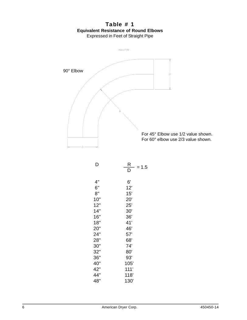
In designing a dryer exhaust duct system it is not necessary to compute the friction loss of the ductwork. American Dryer Corp. recommends that the dryer exhaust duct static pressure not exceed themaximum listed in the dryer installation manual. This maximum allowable static pressure is calculatedto provide maximum dryer efficiency. It is necessary to determine the total equivalent length of the ductsystem. The total equivalent length of the duct system is the actual length of the duct added to theequivalent length of all of the fittings. The equivalent length of a fitting is the length of straight duct of thesame size as the fitting in which the friction losses are equal. Equivalent lengths must be determinedfor all elbows, as well as, any entries which may be incorporated into a common duct system formultiple dryers. The total equivalent length is then used with the total cfm (cubic feet per minute)exhaust rating of the dryer(s) to calculate the minimum round duct diameter. Values of the equivalentlength of specific diameter elbows can be determined from Table #1. When designing a single commonduct system for multiple dryers, each individual dryer exhaust duct enters the main common duct. Theequivalent length of the entry losses for each dryer can be determined from the values listed in Table#2.
6 American Dryer Corp. 450450-14
Table # 1Equivalent Resistance of Round Elbows
Expressed in Feet of Straight Pipe
90° Elbow
For 45° Elbow use 1/2 value shown.For 60° elbow use 2/3 value shown.
D RD
4" 6'6" 12'8" 15'
10" 20'12" 25'14" 30'16" 36'18" 41'20" 46'24" 57'28" 68'30" 74'32" 80'36" 93'40" 105'42" 111'44" 118'48" 130'
= 1.5

450450-14 www.amdry.com 7
Table # 2Equivalent Entry Losses
Expressed in Feet of Straight Pipe
Dia of Pipe 30° 45°
4" 3' 5'6" 5' 7'8" 7' 11'
10" 9' 14'12" 11' 17'14" 13' 21'16" 16' 25'18" 18' 28'20" 20' 32'24" 24' 37'28" 28' 46'30" 31' 49'32" 33' 53'

8 American Dryer Corp. 450450-14
TAB
LE #
3
TOTA
L EQ
UIV
ALEN
T O
F ST
RAI
GH
T D
UC
T IN
FT.
CU. FT. OF AIR PER MINUTE1000
0
200
1000
2000
3000
5000
6000
7000
8000
9000 500
100
300
600
400
700
800
900
12
34
56
78
910
2030
4050
6070
8090
100
200
300
10”
Dia
6” D
ia
8” D
ia
12”
Dia
14”
Dia
16”
Dia
18”
Dia
20”
Dia
22”
Dia
24”
Dia
26”
Dia
28”
Dia
30”
Dia
32”
Dia

450450-14 www.amdry.com 9
TAB
LE #
4
12
34
56
78
910
2030
4050
6070
8090
100
200
300
CU. FT. OF AIR PER MINUTE
1000
00
1000
0
2000
0
3000
0
5000
0
6000
0
7000
0
8000
0
9000
0
4000
0
TOTA
L EQ
UIV
ALEN
T O
F ST
RAI
GH
T D
UC
T IN
FT.
12”
Dia
14”
Dia
16”
Dia
18”
Dia
20”
Dia
22”
Dia
24”
Dia
26”
Dia
28”
Dia
30”
Dia
32”
Dia
34”
Dia
36”
Dia
1500
0
2500
0

10 American Dryer Corp. 450450-14
Once the total equivalent length of duct is determined, Tables #3 and #4 are used to determine theminimum diameter round duct to be used. The dryer(s) cfm is read on the left hand side of the chart.The total equivalent length of duct is read across the bottom. The minimum diameter round duct to beused is read at the intersection of the two.
Each round duct diameter line on the graph represents the maximum limit for each size shown. Whenmaking calculations, if the intersection is in the middle of two diameters, the larger size is chosen (I.E.600 cfm at 30' use 8" diameter).
The following are examples of the procedures to calculate the duct size for a single dryer.
Example 1:
A dryer has an air flow of 600 cfm (cubic feet per minute) and an 8-inch diameter dryer exhaustconnection. The duct run will travel 20 feet and has two (2) - 90 degree elbows. What is the totalequivalent length of the duct system? What will be the minimum diameter round duct to be used?
Solution:
Straight length of duct: 20 FeetFrom Table #1Equivalent length of each 90 degree elbow: 15 Feet x 2 = 30 Feet
Total equivalent length of the duct system: 50 Feet
From Table #3The minimum diameter round duct to be used is 8-inches.
Example 2:
A dryer has an air flow of 1,700 cfm with a 12-inch dryer exhaust connection. The exhaust duct willtravel 50 feet with six (6) 90 degree elbows. What is the total equivalent length of the duct system?What will be the minimum diameter round duct to be used?
Solution:
The initial total equivalent length of the duct system must first be calculated using the dryer exhaustconnection size.
Straight length of duct: 50 FeetFrom Table 1Equivalent length of each 12" 90 degree elbow: 25 Feet x 6 = 150 Feet
Total equivalent length of the duct system: 200 Feet
From Table 3The minimum diameter round duct to be used is 16-inches.

450450-14 www.amdry.com 11
Because the minimum diameter round duct to be used calculates to a size which is larger than thedryer exhaust connection, the total equivalent length of the duct system must be recalculated using the16" diameter equivalent lengths. This new total length is then used with the dryer(s) cfm to verify thatit still falls within the 16" diameter minimum round duct area.
Straight length of duct: 50 FeetFrom Table 1Equivalent length of each 16" 90 degree elbow: 36 Feet x 6 = 216 Feet
Total equivalent length of the duct system: 266 Feet
From Table 3The minimum diameter round duct to be used is 16-inches.
When calculating and sizing a common exhaust duct for two (2) or more dryers, several steps arerequired. First, the main common duct size is calculated using the total cfm of all of the dryers and thetotal equivalent length of the duct system. Second, the individual dryer exhaust ducts, which travel tothe common duct, are calculated.
Tables 5 and 6 are used to determine the initial common duct size to use in the calculation of the totalequivalent length of the duct system. The total cfm of all of the dryers are added and found on the leftside of the chart. The friction loss (static pressure) is listed at the bottom of the chart. The value of .3"water column is used at the bottom of the chart. This is the maximum recommended static pressurefor the dryer exhaust. The initial minimum diameter round duct is then read at the intersection of thetotal cfm and the .3" water column value. This initial duct size is then used to calculate the totalequivalent length of the duct system.

12 American Dryer Corp. 450450-14
TABLE # 5
Friction Loss in Inches of Water per 100 FT
AIRFLOW
CFM
10000
1000
100
10.001 .01 .1 .2 .3 1 10
24” Duct
22” Duct
20” Duct
18” Duct
16” Duct
14” Duct
12” Duct
10” Duct
8” Duct
6” Duct

450450-14 www.amdry.com 13
TABLE # 6
Friction Loss in Inches of Water per 100 FT
AIRFLOW
CFM
10000
1000.01 .1 .2 .3 1 10
100000
36” Duct
32” Duct
28” Duct
24” Duct
34” Duct
30” Duct
26” Duct

14 American Dryer Corp. 450450-14
The following examples show how a single common duct for multiple dryers is calculated.
Example 1:
There are three (3) dryers with 600 cfm each which will be connected to one (1) common exhaustduct. The dryers have an 8" diameter exhaust connection. The main duct will have a total run of 70 feetand include three (3) 90 degree elbows and two (2) 45 degree elbows. Each individual dryer duct willtravel ten (10) feet and have one (1) 90 degree elbow, one (1) 45 degree elbow, and enter the commonduct at a 45 degree angle. What is the total equivalent length of the common duct system? What is theminimum diameter of the main common duct? What is the total equivalent length of the individual dryerducts? What is the minimum diameter of the individual dryer ducts?
Solution:
To determine the total equivalent length and minimum diameter round duct of the main common duct.
From Table 5The intersection of 1,800 cfm (total of 3 dryers at 600 cfm each) and the static pressure of .3" watercolumn is 14" diameter duct. This is the initial size used in calculations.
Straight length of duct: 70 FeetFrom Table 1Equivalent length of each 14" 90 degree elbow: 30 Feet x 3 = 90 FeetEquivalent length of each 14" 45 degree elbow: 15 Feet x 2 = 30 Feet
Total equivalent length of the common duct: 190 Feet
From Table 3The minimum diameter round duct for the common duct is 16-inches.
The total equivalent length must be recalculated using 16" diameter equivalent lengths to determine thetotal equivalent length. This is necessary because the minimum size shown on Table 3 exceeded theinitial size obtained in Table 5. This recalculation is required because the initial size obtained in Table 5is calculated on a total equivalent length of duct of 100 feet.
When the calculated total equivalent length exceeds 100 feet, the minimum diameter , in most cases,increases.
Straight length of duct: 70 FeetFrom Table 1Equivalent length of each 16" 90 degree elbow: 36 Feet x 3 = 108 FeetEquivalent length of each 16" 45 degree elbow: 18 Feet x 2 = 36 Feet
Total equivalent length of the common duct: 214 Feet
From Table 3The minimum diameter round duct for the common duct is 16-inches.
To determine the total equivalent length and minimum diameter round ducts for the individual dryerexhausts.

450450-14 www.amdry.com 15
When calculating and sizing the individual dryer exhaust ducts, the dryer's exhaust connection size isinitially used to determine the total equivalent length.
Straight length of duct: 10 FeetFrom Table 1Equivalent length of each 8" 90 degree elbow: 15 Feet x 1 = 15 FeetEquivalent length of each 8" 45 degree elbow: 7-1/2 Feet x 1= 7-1/2 FeetFrom Table 2Equivalent length of entry loss at 45 degree angle for 8": 11 Feet
Total equivalent length of each individual dryer duct: 43-1/2 Feet
From Table 3The minimum diameter round duct for each individual dryer duct is 8-inches.
NOTE: The dryer exhaust duct must never be decreased from the dryer's exhaust connectionsize.
Example 2:
There are four (4) dryers which will be connected into a main common duct. The common duct willtravel 45 feet and include four (4) 90 degree elbows. There are two (2) dryers with 2,000 cfm eachwhich have a 12" exhaust connection, one (1) dryer with 1,500 cfm which has a 10" exhaust connection,and one (1) dryer with 800 cfm which has an 8" exhaust connection. Each individual dryer exhaustduct will travel 15 feet and include one (1) 90 degree elbow, one (1) 45 degree elbow, and will enter thecommon duct at a 45 degree angle. What is the total equivalent length of the common duct? What isthe minimum diameter round duct to be used for the common duct? What is the total equivalent lengthand minimum diameter round duct for each of the individual dryer ducts?
Solution:
To determine the total equivalent length of the main common duct.
From Table 5The intersection of 6,300 cfm (total cfm of 4 dryers) and the staticpressure of .3" water column is 22" diameter duct. This is the initial size used in calculations.
Straight length of duct: 45 FeetFrom Table 1Equivalent length of each 22" 90 degree elbow: 1 Feet x 4 = 204 Feet
Total equivalent length of the common duct: 249 Feet
From Table 3The minimum diameter round duct for the common duct is 28-inches.

16 American Dryer Corp. 450450-14
The total equivalent length must be recalculated using 28" diameter equivalent lengths to determine thetotal equivalent length. This is necessary because the minimum size shown in Table 3 exceeded theinitial size obtained from Table 5.
Straight length of duct: 45 FeetFrom Table 1Equivalent length of each 28" 90 degree elbow: 68 Feet x 4 = 272 FeetTotal equivalent length of the common duct: 317 Feet
From Table 3The minimum diameter round duct for the common duct is 28-inches.
To determine the total equivalent length and minimum diameter round duct for the individual dryerducts.
For the dryers with 2,000 cfm each with a 12" diameter exhaust connection.
Straight length of duct: 15 FeetFrom Table 1Equivalent length of each 12" 90 degree elbow: 25 Feet x 1 = 25 FeetEquivalent length of each 12" 45 degree elbow: 12-1/2 FeetFrom Table 2Equivalent length of entry loss at 45 degree angle for 12": 17 Feet
Total equivalent length of each individual dryer duct: 69-1/2 Feet
From Table 3The minimum diameter round duct for each individual dryer duct is 14-inches.
The total equivalent length must be recalculated using 14" diameter equivalent lengths to determinethe total equivalent length. This is necessary because the minimum size shown in Table 3 exceedsthe dryer exhaust connection size used initially.
Straight length of duct: 15 FeetFrom Table 1Equivalent length of each 14" 90 degree elbow: 30 FeetEquivalent length of each 14" 45 degree elbow: 15 FeetFrom Table 2Equivalent length of entry loss at 45 degree angle for 14": 21 Feet
Total equivalent length of the individual dryer duct: 81 Feet
From Table 3The minimum diameter round duct for the individual dryer duct is 14-inches.

450450-14 www.amdry.com 17
For the dryer with 1,500 cfm with a 10" diameter exhaust connection.
Straight length of duct: 15 FeetFrom Table 1Equivalent length of each 10" 90 degree elbow: 20 FeetEquivalent length of each 10" 45 degree elbow: 10 FeetFrom Table 2Equivalent length of entry loss at 45 degree angle for 10": 14 Feet
Total equivalent length of the individual dryer duct: 59 Feet
From Table 3The minimum diameter round duct for the individual dryer duct is 12-inches.
The total equivalent length must be recalculated using 12" diameter equivalent lengths to determine thetotal equivalent length. This is necessary because the minimum size shown in Table 3 exceeds thedryer exhaust connection size used initially.
Straight length of duct: 15 FeetFrom Table 1Equivalent length of each 12" 90 degree elbow: 25 Feet x 1 = 25 FeetEquivalent length of each 12" 45 degree elbow: 12-1/2 Feet
From Table 2Equivalent length of entry loss at 45 degree angle for 12": 17 Feet
Total equivalent length of each individual dryer duct: 69-1/2 Feet
From Table 3The minimum diameter round duct for each individual dryer duct is 12-inches.
For the dryer with 800 cfm with an 8" diameter exhaust connection.
Straight length of duct: 15 FeetFrom Table 1Equivalent length of each 8" 90 degree elbow: 15 FeetEquivalent length of each 8" 45 degree elbow: 7-1/2 FeetFrom Table 2Equivalent length of entry loss at 45 degree angle for 8": 11 Feet
Total equivalent length of the individual dryer duct: 48-1/2 Feet
From Table 3The minimum diameter round duct for the individual dryer duct is 10-inches.
18 American Dryer Corp. 450450-14
The total equivalent length must be recalculated using 10" diameter equivalent lengths to determine thetotal equivalent length. This is necessary because the minimum size shown in Table 3 exceeds thedryer exhaust connection size used initially.
Straight length of duct: 15 FeetFrom Table 1Equivalent length of each 10" 90 degree elbow: 20 FeetEquivalent length of each 10" 45 degree elbow: 10 FeetFrom Table 2Equivalent length of entry loss at 45 degree angle for 10": 14 Feet
Total equivalent length of the individual dryer duct: 59 Feet
From Table 3The minimum diameter round duct for the individual dryer duct is 10-inches.
Notice that, at times, it is necessary to connect a larger duct than what the dryer has for an exhaustconnection. This is required in order to keep the static pressure within the maximum allowable of .3"water column.
It is often necessary to use either square or rectangular duct instead of round. This may be requireddue to constricted passageways. In these instances, it is necessary to use a size which has the samefriction loss as the round duct. Table 7 lists the minimum cross sectional area equivalents of the roundducts. When using rectangular ducts, the length to width ratio must not exceed 3-1/2 to 1.
In some cases it is impossible to meet the minimum size requirements. This may be due to exhaustduct size limitations. In these cases, a booster fan is required in order to meet the recommendedstatic pressure requirements. In an exhaust duct system with individual dryer vents, a booster fan isadded to each individual duct. It is more difficult when installing a booster fan into a common duct formultiple dryers. In this case, each dryer should be fitted with a barometric damper to compensate forthe increased airflow created by the fan. In either case, a HVAC (heating, ventilating, air-conditioning)engineering firm should be consulted.
Should any value exceed the limitations in the tables provided, please consult a HVAC engineering firm.The information given is to assist in the calculation of an exhaust duct system. It may also be used tocheck the sizing of an existing exhaust duct system to verify whether it is within the recommendedguidelines.

450450-14 www.amdry.com 19
TABLE # 7
681012141618202224262830323436
Minimum EquivalentRound Duct Diameter Cross Sectional Area
(Inches) (Square Inches)
305480120164210256324400464540650730840960
1,056

20 American Dryer Corp. 450450-14
Problem 1: Three dryers are to be installed into a laundromat. Each dryer has an air flow of 400cfm and a six (6) inch exhaust connection. Each dryer will be vented separately. Eachdryer exhaust will travel 35 feet and have three (3) 90 degree elbows and one (1) 45degree elbow. What is the total equivalent length and minimum diameter round duct tobe used for each dryer duct?
Problem 2: A nursing home is installing a new dryer which has an air flow of 2,500 cfm and a 14"diameter exhaust connection. The exhaust duct will travel 60 feet and have two (2) 90degree elbows and three (3) 45 degree elbows in the run. What is the total equivalentlength and minimum diameter round duct to be used?
Problem 3: A laundromat owner plans to expand his business. He wants to install eight (8) newdryers which have an air flow of 600 cfm each and an eight (8) inch dryer exhaustconnection. He plans to separate the dryers so that there will be two (2) commonexhaust ducts with four (4) dryers into each one. Each of the two ducts will travel 43feet and have three (3) 90 degree elbows. Each individual dryer duct will travel 10 feetand have one (1) 90 degree elbow, one (1) 45 degree elbow, and enter the main commonduct at a 45 degree angle. What is the total equivalent length and minimum diameterround duct for each common duct? What is the total equivalent length and minimumround duct diameter for each individual dryer exhaust duct?
Problem 4: An institutional laundry is planning on opening in several months. They are currentlyinstalling three (3) dryers. One dryer has an air flow of 2,100 cfm with a 12" diameterexhaust connection. One dryer has an air flow of 1,700 cfm with a 12" diameter exhaustconnection. One dryer has an air flow of 900 cfm with a 8" diameter exhaust connection.The three (3) dryers are to be vented into one (1) common duct. The common duct willtravel 55 feet and have two (2) 90 degree elbows. Each of the individual dryer ducts willtravel 10 feet and have one (1) 90 degree elbow, one (1) 45 degree elbow, and enter thecommon duct at a 45 degree angle. What is the total equivalent length and minimumdiameter round duct for the common duct? What are the total equivalent lengths andminimum round duct diameters for each individual dryer duct?
ANSWERS FOUND ON PAGE 21

450450-14 www.amdry.com 21
Answers: #1 - The total equivalent length is 87-1/2 feet and the minimum round diameter duct is8-inches.
#2 - The total equivalent length is 203-1/2 feet and the minimum round diameter duct is18-inches.
#3 - The total equivalent length of the common duct is 166 feet and has a minimumdiameter of 18-inches.
Each of the individual dryer ducts has a total equivalent length of 43-1/2 feet and athe minimum round diameter duct is 8-inches.
#4 - The total equivalent length of the common duct is 157 feet and has a minimumdiameter of 22-inches.
The dryer with 2,100 cfm has a total equivalent length of 76 feet and a minimum rounddiameter duct of 14-inches.
The dryer with 1,700 cfm has a total equivalent length of 64-1/2 feet and a minimumround diameter duct of 14-inches.
The dryer with 900 cfm has a total equivalent length of 54 feet and a minimum rounddiameter duct of 10-inches.

ADC 450450 14-03/01/05-0