exact interconnect parasitic characterization - silvaco · exact interconnect parasitic...
TRANSCRIPT
EXACT Interconnect Parasitic Characterization
Application Examples
EXACT – Application Examples
Introduction
EXACT delivers the most accurate interconnect models for nanometer semiconductor processes and generates layout parameter extraction (LPE) rule files for leading full chip extraction tools
EXACT’s powerful 3D field solvers support xCalibre, Calibre xRC, Diva, Assura RCX, and Dracula LPE
- 2 -
EXACT – Application Examples
Introduction: Exact Flow
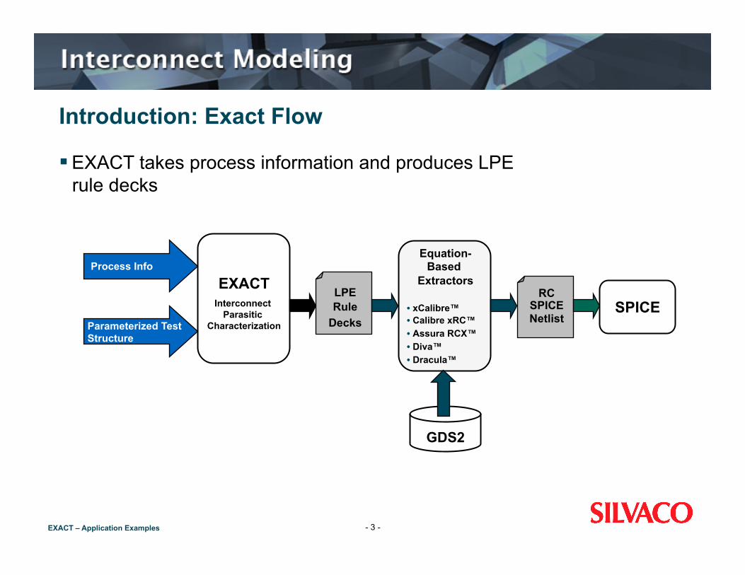
EXACT takes process information and produces LPE rule decks
- 3 -
Process Info
Parameterized Test Structure
EXACT Interconnect
Parasitic Characterization
LPE Rule
Decks
Equation-Based
Extractors
• xCalibre™ • Calibre xRC™ • Assura RCX™ • Diva™ • Dracula™
RC SPICE Netlist
SPICE
GDS2
EXACT – Application Examples
Introduction: Key Benefits
Powerful 3D solver supports non-planar semiconductor profiles and dummies
3D field solver calculates interconnect capacitance models Intuitive and user-friendly graphical interface for process layer
description and test structure definition Standard mode of operation handles most conventional processes Integrated scripting language provides custom LPE rule files for
other extraction tools Powerful statistical analysis module option available to calculate
variations of capacitance
- 4 -
EXACT – Application Examples
Introduction: Ease of Use and Adoption
Easy to use, menu-driven graphical interface for process layer definition
Menu-driven parameterized layout generator for test structure and pattern generation
Easy LPE rule generation with LISA™ scripting language Flexible architecture for fitting raw parasitic data into a wide range
of custom equations for xCalibre/Calibre xRC, and Assura-RCX/Diva/Dracula LPE
Easy to understand extracted capacitance tables that facilitate the analysis of effects on interconnect due to various process change or experiment
Automatic mesh and deck generation and submission to 3D field solver
- 5 -
EXACT – Application Examples
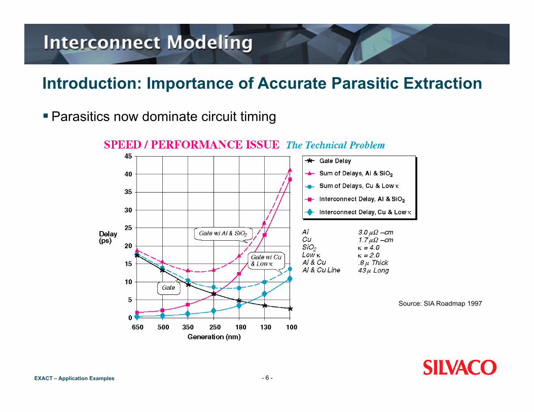
Introduction: Importance of Accurate Parasitic Extraction
Parasitics now dominate circuit timing
- 6 -
Source: SIA Roadmap 1997
EXACT – Application Examples
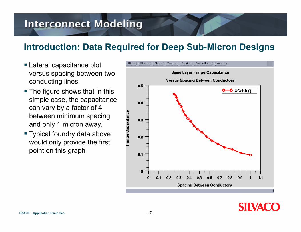
Introduction: Data Required for Deep Sub-Micron Designs
Lateral capacitance plot versus spacing between two conducting lines
The figure shows that in this simple case, the capacitance can vary by a factor of 4 between minimum spacing and only 1 micron away.
Typical foundry data above would only provide the first point on this graph
- 7 -

EXACT – Application Examples
Introduction: Data Required for Deep Sub-Micron Designs (con’t) What should the LPE Tool do if only the minimum spacing
coefficient data are provided... Guess? Ignore? Use the value for minimum spacing?
None of the above options are acceptable for deep sub-micron technologies . An accurate value must be known for all geometries
Different widths of conductor and other geometries require different capacitance coefficients
E.g., A line over a line will result in a significantly different coefficient value compared to a line over a ground plane.
- 8 -
EXACT – Application Examples
Introduction: Data Required for Deep Sub-Micron Designs (con’t) Other typical configurations
1/ Co-incident edges 2/ Cross overs 3/ Corners 4/ Proximity effects
EXACT can generate coefficients for ANY structure
- 9 -

EXACT – Application Examples
Workshop Summary
Getting started Defining a process flow
(i) Simple processing using the Interactive Tool (ii) Advanced process flow
Defining and editing layout Test structures Defining the “Design of Experiments” (DOE) Executing the experiments Processing the data
- 10 -
EXACT – Application Examples
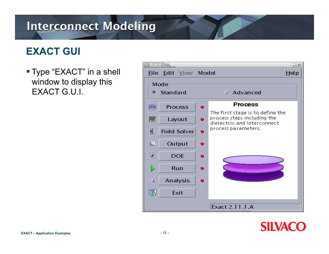
EXACT GUI
Type “EXACT” in a shell window to display this EXACT G.U.I.
- 11 -
EXACT – Application Examples
5 Stages of EXACT
EXACT takes you through the 5 stages sequentially: STAGE 1 Process Stage: Define the process STAGE 2 Layout Stage: Define or load the test structure mask layouts STAGE 3 Design of Experiments Stage: Select which experiments STAGE 4 Run Stage: Run the experiments using the 3D process
simulator and field solver STAGE 5 Analysis Stage: Write or import a script to process all the data
- 12 -
EXACT – Application Examples
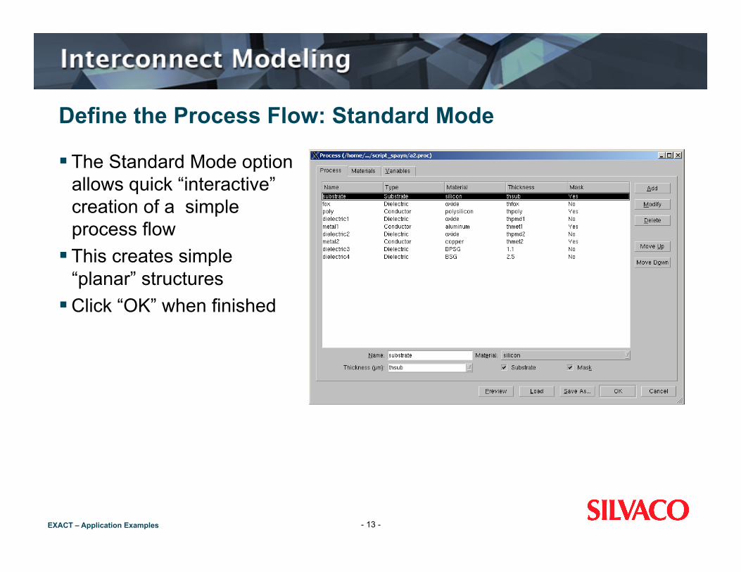
Define the Process Flow: Standard Mode
The Standard Mode option allows quick “interactive” creation of a simple process flow
This creates simple “planar” structures
Click “OK” when finished
- 13 -

EXACT – Application Examples
Define the Process Flow: Advanced Mode
The Advanced Mode option allows the use of realistic photolithography, deposition or etching to create the test structures:
In the Advanced mode users can: i. create their own process flow ii. edit a previous process flow from the interactive (from the Standard
Mode) builder iii. edit a CLEVER input deck
We shall only deal with the Standard Mode option in this workshop
- 14 -

EXACT – Application Examples
Process Preview with the Internal Viewer of EXACT
Having entered the process via the Standard Mode, the process verification is made possible using the “process preview” button in the process GUI
- 15 -
EXACT – Application Examples
Layout Stage
After having entered the process the test structure specific to which required capacitance coefficient are then loaded into EXACT Standard generic test structures will be provided for various Extraction
(LPE) Tools Load test structures using the layout GUI The layout GUI also allows user to create their own test structures
using the “more options” mode of EXACT layout GUI
- 16 -

EXACT – Application Examples
Example of a Layout Test Structure
An example of a layout test structure is shown here
From the test structure capacitances such as near body capacitance (the capacitance between two wires of the same process layer) are easily obtained
- 17 -
EXACT – Application Examples
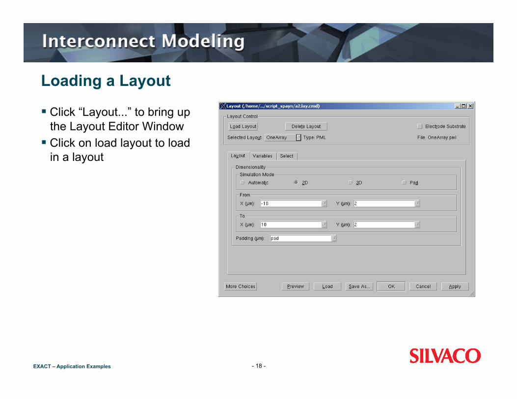
Loading a Layout
Click “Layout...” to bring up the Layout Editor Window
Click on load layout to load in a layout
- 18 -
EXACT – Application Examples
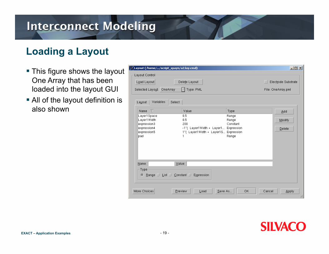
Loading a Layout
This figure shows the layout One Array that has been loaded into the layout GUI
All of the layout definition is also shown
- 19 -

EXACT – Application Examples
Creating a Layout: More Choices
By clicking on the “more choices” button in the layout GUI users have the ability to create a layout
User defined layout: “layers” and “wires” button are added to allow you to define any kind of layout
- 20 -

EXACT – Application Examples
Layout: Combination Selection
Which process layers are assigned to which layout layers is performed via the combination selection in the layout GUI
Select these by clicking on “Select” You may not be interested in all of
them For example, you may not be
interested in calculating the capacitance between Metal 4 and the substrate because they are very far apart
You can select such combination individually, or use the automatic selection
- 21 -
EXACT – Application Examples
Layout: Preview
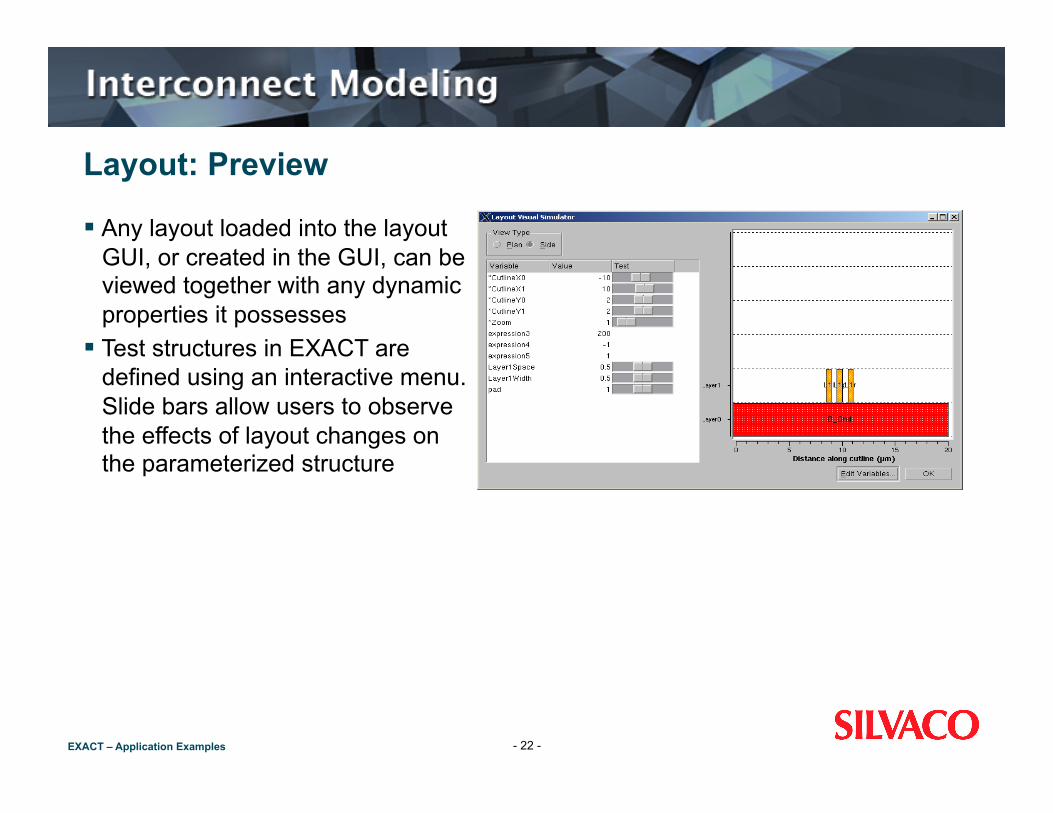
Any layout loaded into the layout GUI, or created in the GUI, can be viewed together with any dynamic properties it possesses
Test structures in EXACT are defined using an interactive menu. Slide bars allow users to observe the effects of layout changes on the parameterized structure
- 22 -
EXACT – Application Examples
Layout: Preview
To see each structure click on “preview” For plane view, click “plan” To see a cross-sectional view “side” This gives a cutline using the user definable co-ordinates in the 2D
Cutline box To visualize the effect of varying the layout parameters, move
sliders When in 2D or 3D mode use the sliders to vary the parameters
- 23 -
EXACT – Application Examples
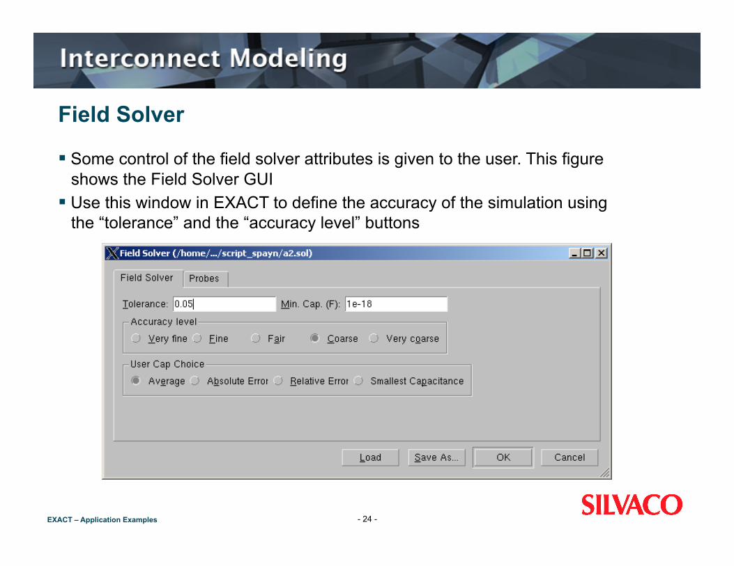
Field Solver
Some control of the field solver attributes is given to the user. This figure shows the Field Solver GUI
Use this window in EXACT to define the accuracy of the simulation using the “tolerance” and the “accuracy level” buttons
- 24 -
EXACT – Application Examples
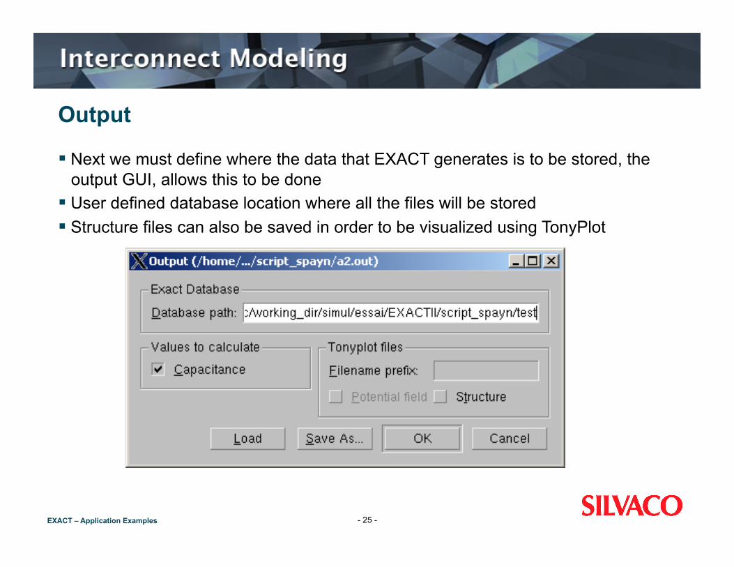
Output
Next we must define where the data that EXACT generates is to be stored, the output GUI, allows this to be done
User defined database location where all the files will be stored Structure files can also be saved in order to be visualized using TonyPlot
- 25 -

EXACT – Application Examples
DOE
The design of experiments stage is entered by clicking on the DOE button
Click “DOE...” to bring up DOE window Use the DOE window to select the
variable ranges and sample points Flexible design of experiment.
(full factorial, stepped, ccc) Ability to change design parameters as
well as process parameters
- 26 -

EXACT – Application Examples
Running Simulations
After having finished setting up the simulation experiments, we can run them by clicking on the run button. The Run GUI open up is shown in this figure
We can can follow the running of the experiment At any stage in the execute window, click on view log shows the exact process
flow being executed for that particular job (see figure on the following page)
- 27 -
EXACT – Application Examples
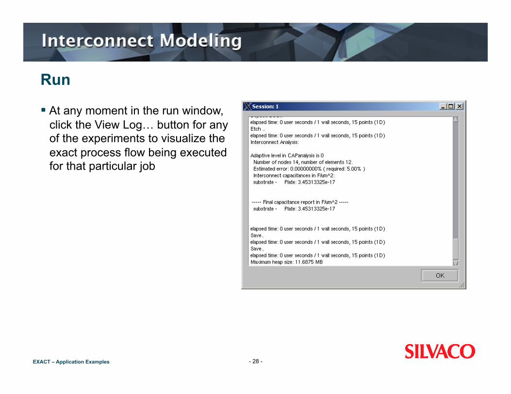
Run
At any moment in the run window, click the View Log… button for any of the experiments to visualize the exact process flow being executed for that particular job
- 28 -
EXACT – Application Examples
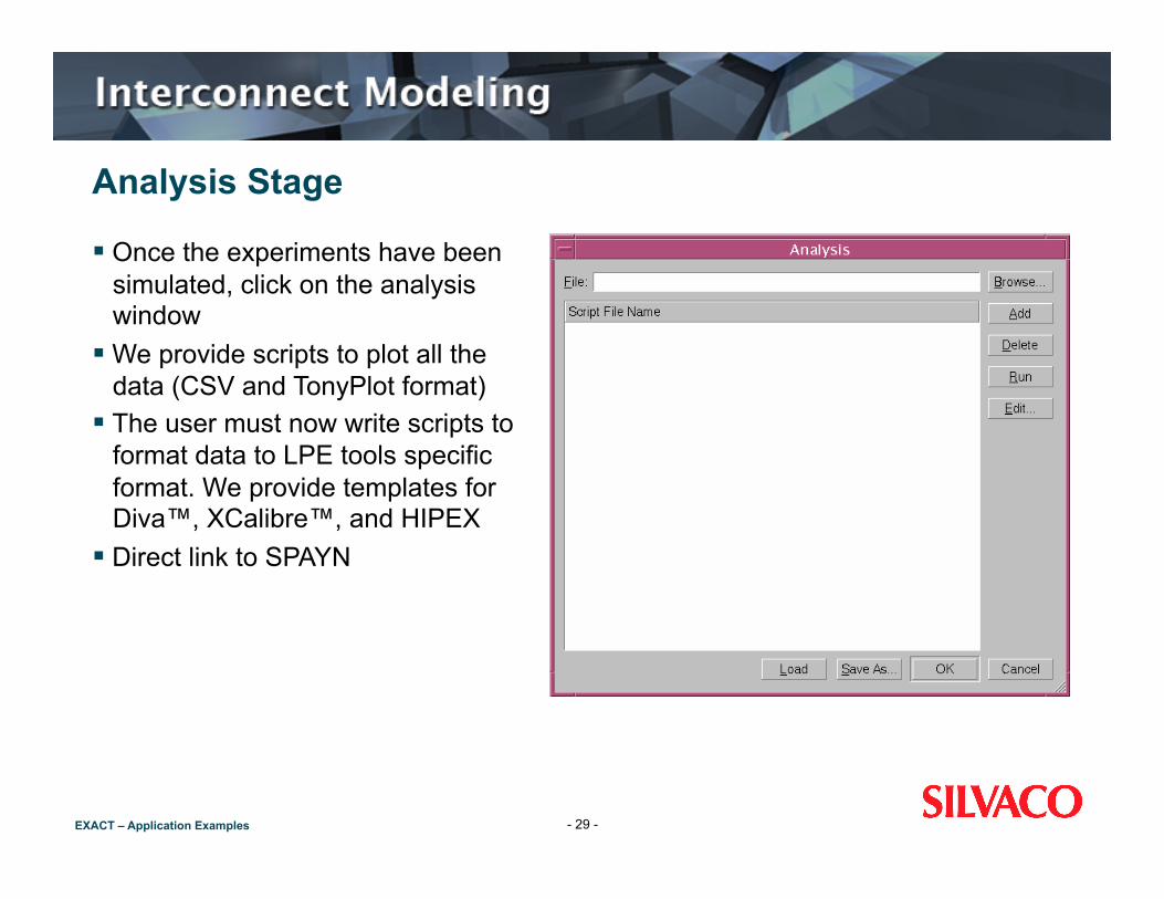
Analysis Stage
Once the experiments have been simulated, click on the analysis window
We provide scripts to plot all the data (CSV and TonyPlot format)
The user must now write scripts to format data to LPE tools specific format. We provide templates for Diva™, XCalibre™, and HIPEX
Direct link to SPAYN
- 29 -
EXACT – Application Examples
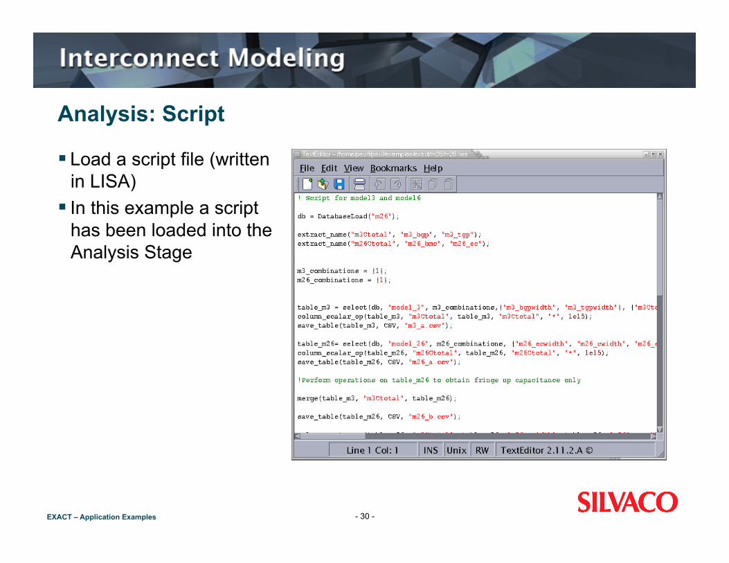
Analysis: Script
Load a script file (written in LISA)
In this example a script has been loaded into the Analysis Stage
- 30 -

EXACT – Application Examples
Analysis: Script Output
Mentor Graphics xCalibre™/Calibre xRC™ rule file generated by EXACT using the associated script file
- 31 -
EXACT – Application Examples
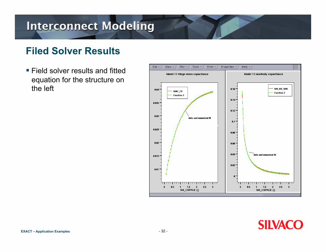
Filed Solver Results
Field solver results and fitted equation for the structure on the left
- 32 -

EXACT – Application Examples
Automatic Models
Exact can automate the generation of parameters for use in Hipex Define a process (in either Standard or Advanced mode) Select the Model->Hipex menu Exact will load a set of pre-defined layouts that it needs, and run a
series of simulations and perform equation fitting to generate the Hipex parameters, all automatically
You can override the default for the variables used Exact saves a LISA file for HIPEX, and saves all of its own project
files
- 33 -

EXACT – Application Examples
Model HIPEX Output
Extract from a HIPEXscript generated with ‘Model Hipex’
- 34 -

EXACT – Application Examples
Summary
Today we have shown you how simple it is to use “EXACT” To create or use existing test structures using a real process flow Either realistic or simple 3D processing can be used Set up and run a design of experiments using a 3D field solver Process the data for LPE tools
EXACT (will) increases the accuracy of full chip parasitic extraction EXACT can be used in conjunction with ANY full chip extraction
tool
- 35 -