ex100/80 saw fence & guide rails - exaktor tools · thank you for choosing the exaktor®...
TRANSCRIPT
1/11/2005
1
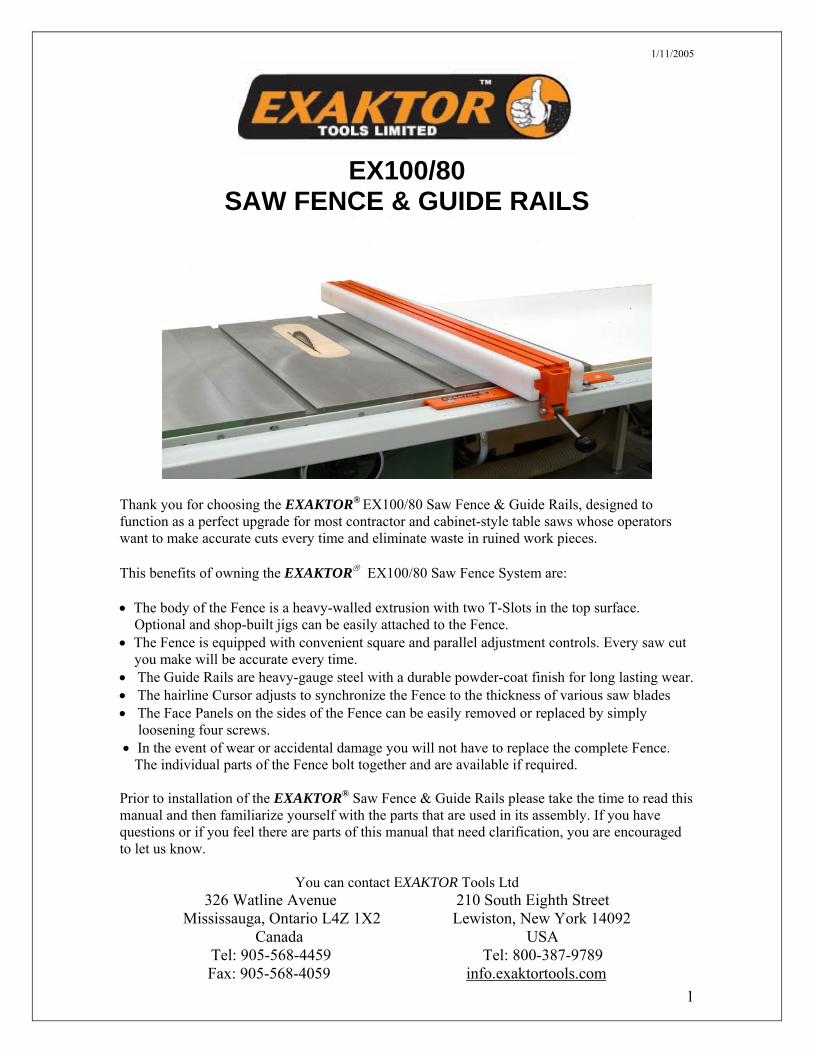
EX100/80 SAW FENCE & GUIDE RAILS
Thank you for choosing the EXAKTOR® EX100/80 Saw Fence & Guide Rails, designed to function as a perfect upgrade for most contractor and cabinet-style table saws whose operators want to make accurate cuts every time and eliminate waste in ruined work pieces. This benefits of owning the EXAKTOR® EX100/80 Saw Fence System are: • The body of the Fence is a heavy-walled extrusion with two T-Slots in the top surface. Optional and shop-built jigs can be easily attached to the Fence. • The Fence is equipped with convenient square and parallel adjustment controls. Every saw cut you make will be accurate every time. • The Guide Rails are heavy-gauge steel with a durable powder-coat finish for long lasting wear. • The hairline Cursor adjusts to synchronize the Fence to the thickness of various saw blades • The Face Panels on the sides of the Fence can be easily removed or replaced by simply loosening four screws. • In the event of wear or accidental damage you will not have to replace the complete Fence. The individual parts of the Fence bolt together and are available if required. Prior to installation of the EXAKTOR® Saw Fence & Guide Rails please take the time to read this manual and then familiarize yourself with the parts that are used in its assembly. If you have questions or if you feel there are parts of this manual that need clarification, you are encouraged to let us know.
You can contact EXAKTOR Tools Ltd
326 Watline Avenue 210 South Eighth Street Mississauga, Ontario L4Z 1X2 Lewiston, New York 14092
Canada USA Tel: 905-568-4459 Tel: 800-387-9789Fax: 905-568-4059 info.exaktortools.com
1/11/2005
2
EXAKTOR® EX100/80 INDUSTRIAL SAW FENCE SYSTEM
The EXAKTOR® EX100/80 Industrial Saw Fence & Guide Rails can be used in conjunction with most table saws. The E100 Saw Fence has been designed to be compatible with the existing 2”x 3” guide rail systems on Biesemeyer®, Delta®, General®, Jet®, Powermatic® and similar commercial table saw fences. The Fence is also available with a pair of 80”EX80 guide rails that will give you up to 60” in rip capacity to retrofit table saws that have a minimum table edge depth of 1½”.
Constructed from a thick-walled aluminum extrusion with a durable powder-coat finish, the Fence has two T-Slots in its top surface for attaching hold-downs and other shop-built jigs and devices. The quick-action cam locking lever and convenient squaring and parallel adjustment controls will enable you to set the Fence for accurate cuts every time.
What sets this Fence apart is its design and construction. Unlike most other commercial
grade table saw fences that are constructed from parts that are welded together, the EX100 Fence has been designed and built with all of its components being replaceable in the event of accidental damage, and it is available with easily changed face panels that meet the top surface of the table saw for cutting veneers or laminates, eliminating catching thin materials under the fence body.
The Fence can be used with or without face panels. There are no fixtures on the sides of
the fence body to interfere with work being processed. The face panel system enables the left and/or right side face panels to be removed or replaced by simply loosening four screws. This allows for the replacement of damaged face panels or the attachment of shop-built jigs and fixtures.
The Fence body measures 2½”x 3”x 40”, the two face panels are ¾”x 2⅝ ”x 40½” and
the T-bar is 16” long for alignment against the Front Guide Rail. Drawings are included for the construction of a shop-made extension table. To support
the extension table and 80” long rails, table legs are required. The (optional) Table Legs are tubular steel with a powder-coat finish and have adjustable leveling feet.
Designed for Use With Table Saws Only The EXAKTOR® EX100/80 Saw Fence & Guide Rail system is sold for use with table saws only. It must be used with, and does not eliminate the need for, anti-kick-back and splitter devices. These devices are not supplied with the EX100/80 Saw Fence & Guide Rail system. The provision of a splitter and anti-kick-back device is the responsibility of the saw owner and/or user.
WARNING: NO PART OF THIS MANUAL MAY BE REPRODUCED IN ANY FORM WITHOUT THE WRITTEN APPROVAL OF EXAKTOR® TOOLS LTD.
© EXAKTOR® Tools Ltd, 2004

1/11/2005
3
TABLE SAW SAFETY
1. To prevent accidents keep safety in mind while you work. 2. Use the safety guards installed on powered equipment. They are for
your protection. 3. When working on powered equipment keep fingers away from saw
blades and cutters. 4. Wear safety goggles to prevent injuries from flying wood chips and
saw dust. 5. Wear headphones to protect your hearing. 6. Consider installing a dust vacuum to reduce the amount of airborne
dust in your workshop. 7. Don’t wear loose clothing, such as neckties or shirts with loose
sleeves, or jewelry, such as rings, necklaces or bracelets when working on power equipment.
8. Tie back long hair to prevent it from getting caught in powered equipment.
9. Keep work areas clean. Cluttered areas invite accidents. 10. Do not force work though the machine. Tools work better and are
safer when they work at their own speed. 11. Do not overreach. Keep proper footing and balance at all times. 12. Do not reach behind the machine to grab a cutoff piece. If the wood
binds behind and against the blade or cutter it will kick back faster than you can let go.
13. Disconnect the machine from electrical power before servicing and changing accessories, such as blades and cutters.
14. Never leave the machine running unattended – turn the power off. 15. Do not leave the machine until it comes to a complete stop. 16. Do not operate a machine if you are mentally or physically fatigued. 17. If there is something that you do not understand, do not operate the
machine! Ask for help first.
These safety rules do not cover every situation in a workshop. Consider your conditions when using your EXAKTOR® Saw Fence.
© EXAKTOR® Tools Ltd, 2004

1/11/2005
4
EXAKTOR® EX100/80 T-SLOT INDUSTRIAL SAW FENCE SYSTEM CAUTION! When using the EXAKTOR® T-Slot Saw Fence, and before operating the saw, make absolutely sure that no part of the Saw Fence assembly can touch or come in contact with the saw blade at any time whether or not the machine is in operation. The EXAKTOR® T-slot Saw Fence will make your table saw a precision wood cutting machine designed to meet the needs of the table saw operator who requires a precision saw fence built to hold up in hard working conditions. This saw fence system is simple to adjust, and is guaranteed to maintain adjustments for maximum accuracy. Manufactured from high quality materials, the EXAKTOR® Saw Fence and Guide Rails are easily installed on most table saws. Alternatively, just the Fence without the Guide Rails can be an upgrade replacement for older or worn-out table saw fences that use a Biesemeyer®, or similar 2”x 3” square tubular front guide tube. HIGH-STRENGTH ALUMINUM, BUILT TOUGH TO LAST The Fence body is a thick-walled, high-strength aluminum extrusion, with a baked-on powder coat finish. The Fence body slides smoothly on the front Guide Rail and on the top of the saw table. Both sides of the Fence are equipped with hard wearing UHPE plastic panels providing you with a smooth wear resistant surface for sliding wood against the Fence. The Panels are easily removed or replaced. This allows quick replacement of damaged Panels or the attachment of custom jigs or fixtures. T-Slots in the top surface of the Fence body provide a secure and versatile way to attach optional accessories and shop-built jigs. The Fence Locking Handle quickly positions and locks the Fence for cutting on either the right or left side of the saw blade without any dismantling and re-assembly. The restrictive type locking ensures that the Fence stays parallel to the saw blade when it is moved, and its positive locking on the front Guide Rail keeps the Fence from moving and shifting out of position without the need for additional clamps.
STEEL GUIDE RAILS Front and rear Guide Rails are fabricated from heavy gauge steel with a baked-on powder coat finish. They are easily installed on most table saws, and can be positioned to the right or left of the saw blade, as required. The steel Measuring Scale and its adjustable hair-line Cursor will allow you to accurately position the Saw Fence with different saw blades eliminating wrong cuts and work spoilage. EASILY ADJUSTED FOR PARALLELISM The saw fence is easily adjusted for parallelism to the saw blade and for squaring to the saw table. When moved into position, both ends of the Fence body move the same distance at the same time, with the Fence remaining parallel to the saw blade, or at any lead in relation to the saw blade the user may establish. ADJUSTABLE WORK STOPS The underside of the front Guide Rail can be equipped with optional Work Stops that are easily moved to let you quickly position the Fence to repeat measured cuts accurately. Or, the front Guide Rail can be equipped with an optional ProScale® Digital Read-Out, to set the Fence position to 1/100”, and eliminate guesswork in reading and interpreting manual scales.

1/11/2005
5
QUICK INSTALLATION Following the step-by-step instructions, the EXAKTOR® saw fence system is designed to retrofit most table saws that have a minimum table edge depth of 1½”, including Craftsman®, Delta®, General®, Jet®, Powermatic®, Rexon®, Walker-Turner® etc. RELIABILITY AND GUARANTEE EXAKTOR® Industrial T-Slot Saw Fences have been carefully designed and are manufactured using computer controlled laser cutting and fabrication machinery. The EXAKTOR® Saw Fence system includes the parts for assembly of the Fence, front Guide Rail, front Guide Rail Tube, rear Guide Rail and the Mounting Hardware for attaching the fence system to
many different types and styles of table saws. Instructions are included to construct a supporting extension table. The optional Leg Kit used to support the extension table, and the T-Slot Channel with Work Stops must be ordered separately. IMPORTANT: The 80” Guide Rails provided with the EXAKTOR® Saw Fence system must be used with a supporting extension table with legs in place. All EXAKTOR® products are protected with the Ultimate Guarantee that covers both materials and workmanship for as long as you own them and, in the event of damage, any part of the fence system can be replaced saving you the cost of a complete replacement
1/11/2005
6
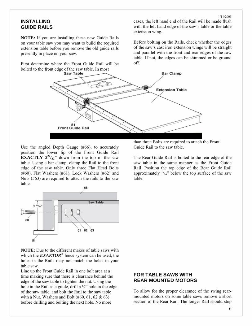
INSTALLING GUIDE RAILS NOTE: If you are installing these new Guide Rails on your table saw you may want to build the required extension table before you remove the old guide rails presently in place on your saw. First determine where the Front Guide Rail will be bolted to the front edge of the saw table. In most
cases, the left hand end of the Rail will be made flush with the left hand edge of the saw’s table or the table extension wing. Before bolting on the Rails, check whether the edges of the saw’s cast iron extension wings will be straight and parallel with the front and rear edges of the saw table. If not, the edges can be shimmed or be ground off.
Use the angled Depth Gauge (#66), to accurately position the lower lip of the Front Guide Rail EXACTLY 227/32” down from the top of the saw table. Using a bar clamp, clamp the Rail to the front edge of the saw table. Only three Flat Head Bolts (#60), Flat Washers (#61), Lock Washers (#62) and Nuts (#63) are required to attach the rails to the saw table.
NOTE: Due to the different makes of table saws with which the EXAKTOR® fence system can be used, the holes in the Rails may not match the holes in your table saw. Line up the Front Guide Rail in one bolt area at a time making sure that there is clearance behind the edge of the saw table to tighten the nut. Using the hole in the Rail as a guide, drill a ¼” hole in the edge of the saw table, and bolt the Rail to the saw table with a Nut, Washers and Bolt (#60, 61, 62 & 63) before drilling and bolting the next hole. No more
than three Bolts are required to attach the Front Guide Rail to the saw table. The Rear Guide Rail is bolted to the rear edge of the saw table in the same manner as the Front Guide Rail. Position the top edge of the Rear Guide Rail approximately 1/16” below the top surface of the saw table. FOR TABLE SAWS WITH REAR MOUNTED MOTORS To allow for the proper clearance of the swing rear-mounted motors on some table saws remove a short section of the Rear Rail. The longer Rail should stop

1/11/2005
7
in line with the saw blade. Leave a wide enough space to allow clearance for the motor when the blade is moved from 90° to 45°. The shorter section of Rail is for back table support only. NOTE: If you are installing an EXAKTOR® Sliding Table, the left hand end of the Front Guide Tube and Guide Rail must be cut off or moved to the right and made flush with the left hand edge of the saw table
SUPPORT TABLE A Back Support Table can be easily supported on the Rear Guide Rail. Secure the table to the rail with two small C-Clamps as shown.
BUILDING THE EXTENSION TABLE The Front and Rear Guide Rails are 80” long and will project beyond the right hand edge of the saw table. Build an Extension Table as shown. Make it the same depth “B” (front to rear) as the saw table and the
length “A” equal to the length of the Guide Rails that extend beyond the right hand edge of the saw table. The frame of the table is constructed ¾”x 2¼” clear grained stock with ¾” Panel (plywood or particle board) and a plastic laminate top.
The top surface of the Extension Table must be made level with the saw’s table. Clamp the Extension Table to the Front Guide Rail. Use the Depth Gauge to set the depth of the Rail as was done with the saw table. Using the hole in the Rail as a guide, drill a ¼” hole in the edge of the Extension Table, and bolt the Rail to the Extension Table before drilling and bolting the next hole. No more than three Bolts (#60) with Washers (#61& 62) and Nuts (#63) are required to attach the rail to the Extension Table. The Rear Guide Rail is bolted to the rear edge of the Extension Table in the same manner as the Front Guide Rail. Position the top edge of the Rear Guide Rail approximately 1/16” beneath the top surface of the Extension Table. From underneath the Front Guide Rail (#51), bolt on the Front Guide Tube (#52) using nine ¼ - 28 x ½” Hex Head Bolts (#64) with ¼” Split Lock Washers (#65) in the predrilled and tapped holes.

1/11/2005
8
.
IMPORTANT: After completing the installation of the Guide Rails check to see that the Front Guide Tube is parallel with the top surface of your table saw.
If the Front Guide Rail is not mounted at 90° to the top of the saw table, or there is a slight distortion in the Front Guide Tube, the Front Guide Tube can be out of alignment. The problem is easy to correct. After removing the Front Guide Tube from the Front Guide Rail, place three or four layers of masking tape along the back edge of the holes in the Front Guide Rail. Re-bolt the Front Guide Tube to the Front Guide Rail.
ASSEMBLING THE FENCE Your EXAKTOR® M100 Saw Fence requires some assembly requiring only a few minutes of your time when you proceed as follows: Rather than being manufactured from parts that are welded together, the EXAKTOR® Saw Fence is assembled using a few machine screws. This allows you to easily replace any part of the Fence that may become damaged, without the necessity of you having to replace the complete Fence. With the plastic pads on the Squaring Bar facing away from the T-Bracket, use two ¼-20x⅜” Machine Screws (#12) to attach the Squaring Bar (#4) to the inside of the T-Bracket (#02). Make the Screws tight.

1/11/2005
9
Insert two ¼-20x1/8” adjusting Screws (#16) into the threaded holes from the backside of the T-Bracket causing them to press against the backside of the Squaring Bar.
Thread the two ½-13 x ½” Nylon Grub Screws (#17) into the top surface of the T-Bracket
The Yoke (#5) is already assembled with the locking mechanism for installing in the body of the Fence.
Inset the assembled Yoke (#05) into the end of the Fence Body (#01) aligning the four threaded holes in the bottom of the Yoke with the four clearance holes in the bottom surface of the Fence.
Use four ¼-20x 1½” Machine Screws (#13) inserted through the T-Bracket (#2), the Spacer Block (#3) and the clearance holes in the bottom surface of the Fence, and screw them into the threaded holes in the bottom of the Yoke. Make the Screws tight.

1/11/2005
Insert two ¼-20x½” Machine Screws (#14) through both sides of the Fence Body and screw them into the threaded holes in the sidewalls of the Yoke. Tighten the Screws.
10

1/11/2005
11
INSTALLING FENCE PANELS The Fence Panels (#30) are manufactured from UHPE, a hardwearing plastic with a smooth surface that will allow the work being pushed through the saw blade to slide easily along the Fence. Insert eight ¼-20 x 1” Panel Bolts (#31) through eight Panel Retainers (#32) and thread them part way into the four holes located on each side of the Fence. The backside of the Fence Panel has a T-slot running the full length of the Panel. Slide the T-slot in the Panel over the four Bolts and Retainers. With the Panel centered on the Fence, the front side of the Panel has four small access holes that will lineup with the heads of the Panel Bolts. Using the ⅛” Allen Key provided, insert it into the access hole and tighten the Panel Bolts to cause the Panel Retainers to secure the Panels to the sides of the Fence. NOTE: Panel Bolts allow the operator to adjust the bottom edge of the Fence Panels to touch the top of the saw table. This adjustment will prove helpful when cutting thin materials such as veneers and/or plastic laminates that you do not want to catch under the body of the Fence.
If you want to make your own fence panels, an (optional) kit consisting of a carbide router bit, four Cone Head Setscrews, eight Panel Screws and Retainers, and a ⅛” Allen Key, is available. See enclosed instructions.

1/11/2005
12
INSTALLING THE FENCE IMPORTANT WARNING: Before beginning any installation and/or adjustments to the Fence, be sure the power switch for the table saw is turned OFF and the machine is unplugged from the electrical source. Accidentally starting the saw while installing or making adjustments to the Fence may result in serious personal injury. ADJUSTING FENCE PARALLEL TO THE MITER GUIDE SLOTS First, check that the table saw has been properly adjusted. The saw blade should be parallel to the miter guide slot. If not, refer to the table saw’s manual for the procedure to make the adjustment. The two Adjusting Setscrews (#16) in the T-Bracket are used to adjust the body of the Fence relative to the saw blade and miter guide slot. Using these Setscrews, align the side of the Fence with the miter guide slot. You can easily check to determine if the Fence is parallel along the length of the miter guide slot by running your finger along the edge of the miter guide slot and the Fence. To check and adjust the Fence, move the Fence until the edge of the Fence is in line with the edge of the miter guide slot, and push down on the Fence Locking Lever. Check to see that the Fence is parallel to the entire length of the miter guide slot. If adjustment is required, lift up the fence Locking Lever and raise the T-Bracket up off the Guide Tube. Slightly tighten or loosen the two adjusting Setscrews (#16) … one side IN…one side OUT. Replace the T-Bracket on the Guide Tube and check again to see if the edge of the Fence is parallel with the entire length of the miter gauge slot. Repeat this adjustment until the Fence is absolutely parallel to the miter gauge slot. NOTE: Very little movement of the adjusting setscrews is necessary to make this adjustment.
SQUARING THE SIDE OF THE FENCE TO THE TOP OF THE SAW TABLE Using a try square, adjusting the plastic Grub Screws (#17) will cause the sides of the fence to be square to the top of the saw table. ADJUSTING CLAMPING ACTION OF THE FENCE When the Fence Locking Handle is pushed down to the locking position the Fence assembly should be clamped securely to the Guide Tube. If the Fence is not securely clamped to the Guide Tube, lift the Fence assembly up off the Guide Tube. Slightly tighten both adjusting Setscrews (#16) an equal amount. Replace the Fence assembly onto the Guide Tube and with the Locking Handle pushed down recheck that the Fence assembly is clamped securely to the Guide Tube. IMPORTANT: After adjusting the clamping action of the Locking Handle, re-check that the Fence is still parallel to the miter gauge slot. Adjust if necessary. NOTE: Do not lift the Locking Lever all the way up when moving the Fence. Lift it only high enough to release the locking mechanism.
1/11/2005
13
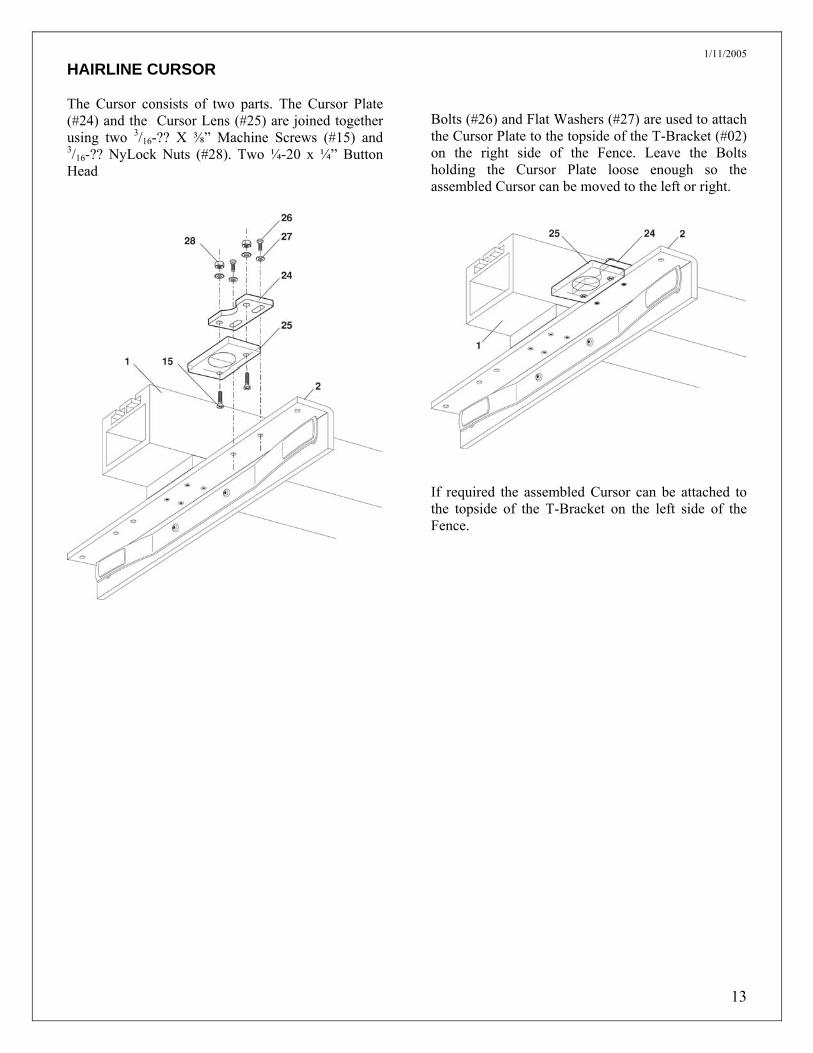
HAIRLINE CURSOR The Cursor consists of two parts. The Cursor Plate (#24) and the Cursor Lens (#25) are joined together using two 3/16-?? X ⅜” Machine Screws (#15) and 3/16-?? NyLock Nuts (#28). Two ¼-20 x ¼” Button Head
Bolts (#26) and Flat Washers (#27) are used to attach the Cursor Plate to the topside of the T-Bracket (#02) on the right side of the Fence. Leave the Bolts holding the Cursor Plate loose enough so the assembled Cursor can be moved to the left or right.
If required the assembled Cursor can be attached to the topside of the T-Bracket on the left side of the Fence.

1/11/2005
14
INSTALLING THE MEASURING SCALE Remove the Fence and thoroughly clean the top surface of the Guide Tube to remove any dust, grease or other dirt. With the Fence on the table saw, positioned on the right side of the saw blade, slide the Fence over until its left side touches the side of the blade. Position the hairline in the Cursor in the center of its range of adjustment and tighten the two button head bolts. Mark the position of the hairline on the top of the Front Guide Tube with a pencil. This is the ZERO mark for applying the self-adhesive Measuring Scale. Using the ZERO mark as the starting point, measure ½” in from the front edge of the Guide Tube and apply the adhesive Measuring Scale. Be careful when laying the scale into position that you maintain the ½” measurement from the front edge of the Guide Tube. Burnish the Measuring Scale into place with heavy thumb pressure. Set the Cursor’s hairline at the 2” mark on the Measuring Scale. Use a piece of some scrap particleboard or plywood and make several cuts. If the Back…or Heel…of the blade is dragging, adjust the Fence again. The Fence must be exactly parallel with the blade before the hairline in the Cursor is set. Very little lever pressure is required to hold the Fence in position on the Guide Tube. To DECREASE pressure let both setscrews OUT the same amount. To INCREASE pressure, turn both setscrews IN the same amount. Again, check to make sure that the body of the Fence remains parallel with the saw blade. Position and lock the Fence with the Cursor’s hairline on the 2” mark. Using scrap material and make a cut. Check the width of the cut material. If the width of the material is not exactly 2”, reset the Cursor hairline to the width of the cut material, and reposition and lock the Fence with the hairline again at the 2” mark. Make another cut and measure the width of the width of the cut material. Continue this procedure, positioning the Fence and setting the Cursor’s hairline in this manner until the cut is EXACTLY 2”.
The thickness of the saw blade and the widths of the kerfs they cut vary with different saw blades, so re-adjustment of the Cursor’s hairline is required whenever you change the type or style of blade. MAINTENANCE Put grease on the Locking Cam and Pressure Pad WEEKLY to prevent wear. Apply paste wax to the Fence, Front Guide Tube and Extension Table DAILY for good operation.

1/11/2005
15
Parts for EXAKTOR®
M100/80 Saw Fence System Part # Description Qty SF01 - Fence Body 1 SF02 - T-Bracket 1 SF03 - Spacer Block 1 SF04 - Squaring Bar 1 SF05 - Yoke 1 SF06 - Locking Cam 1 SF07 - N.A. SF08 - Handle Bar 1 SF09 - Plastic Knob 1 SF10 - Pressure Pad 1 SF11 - N.A. SF12 - Machine Screw 2 Socket ¼-20x⅜” SF13 - Machine Screw 4 Socket ¼-20x1½” SF14 - Machine Screw 4 Socket ¼-20x½” SF15 - Machine Screw 2 Phillips 3/16 x ⅜” SF16 - Adjusting Set Screw 2 ¼-20x⅜” SF17 - Nylon Grub Screw 2
½-13x½” SF18 - N.A. SF19 - Machine Screw 1 Socket ¼-20x1¾” SF20 - Shoulder Bolt 1 ⅜-20x1¼” SF21 - Ny-Lock Nut 1
¼-20
Part # Description Qty SF22 - Ny-Lock Nut 1 5/16-18 SF23 - Ny-Lock Nut 1
¼-20 SF24 - Cursor Plate 1 SF25 - Cursor Lens 1 SF26 - Button Head Bolt 2 Socket ¼-20x¼” SF27 - Flat Washer 2 SF28 - Ny-Lock Nut 2 3/16-?? SF30 - Fence Panel 2 SF31 - Panel Bolt 8 Socket ¼-20 x 1” SF32 - Panel Retaining Washer 8 ¾”dia. SF50 - Rear Guide Rail 1 2”x 2” x 80” SF51 - Front Guide Rail 1 2½”x 2½” x 80” SF52 - Front Guide Tube 1 2”x3”x 80” SF53 - Steel Measuring Tape 1 Reads left to right SF60 – Phillips F/H Bolt 12 ¼-20x1¼” SF61 - Flat Washer 12 ¼” SF62 - Lock Washer 12 ¼” SF63 - Hex Nut 12 ¼-20 SF64 - Hex Head Bolt 9 ¼-28x½” SF65 - Split Lock Washer ¼” 9 SF66 - Depth Gauge 1

1/11/2005
16
MAKING YOUR OWN FENCE PANELS
The (optional) kit consists of: 1 Carbide T-Slot Router Bit #11 Freud # 55-52 4 Cone Head Set Screws ¼-20 x1”
#31 8 - Panel Screws (low head socket)¼-20 x1”
#32 8 - Panel Retaining Washers OD ¾”, ID ⅛” thick)
1 - ⅛” Allen Key Panels can be made from any ¾” thick composition material, plywood, or hardwood, the surfaces of which are smooth and even throughout their length. To cover the full length of the side of the fence, the panel is 40½” long by 2⅝” in height. If you are using hardwood the grain in the wood should run with the length of the panel. For reference, determine and mark the backside and bottom edge of the panel. Thread the socket end of the cone head set screws into threaded holes in one side of the fence. Insert a ⅛” Allen Key through the corresponding hole in the opposite side of the fence and adjust the point of the cone head setscrew just proud of the side of the fence. To mark the position of the access holes on the panels, place the fence upside down on the table saw. With the panel centered on the side of the fence, and the top edge of the panel resting on the saw’s table, press the backside of the panel against the points of the cone head setscrews. Check that all four positions marked are 1⅜” from the bottom edge of the panel. After marking the panels for both the right and left hand side of the fence, remove the setscrews from the fence and set them aside.
With a 3/16” drill centered on the marks drill the four access holes through the panel. Note: Use a backing board to prevent chipping when the drill bit exits the hole. Using the Router Bit supplied, route a T-Slot, the full length, in the backside of the Panel, ½” deep, centered 1⅜” up from the bottom edge of the panel. Insert panel bolts (#31) through panel retainers (#32) and thread them part way into the four threaded holes located on each side of the fence. Slide the panel bolts and retainers into the T-slot in the backside of the fence panel. With the panel centered on the fence the access holes that will lineup with the heads of the Panel Bolts. Using the ⅛” Allen Key provided, insert it into the access hole and tighten each panel bolts to secure the fence panels to the sides of the fence. NOTE: There is sufficient ‘play’ between the Retainers and the T-slot to enable you position the Fence Panels to sit flush to the surface of the saw’s table. (cont.)

1/11/2005
17
Making your own Fence Panels (cont.)

1/11/2005
18
If You Need to Call Customer Service Please complete the following information for future reference: Model Number: EX26, EX26X, EX26S, EX26SX, EX40, EX60, EXOA-2, EX100 (Circle your model number) Invoice Number: …………………………………………………… Date of Purchase: …………………………………………………. Place of Purchase: ………………………………………………… Retain this Owner’s Manual with your sales receipt as a permanent record of your purchase, in the event of theft, fire or warranty service. EXAKTOR® Numbers The Exaktor Solutions Center is our one-stop resource for all of your Exaktor tool needs. You can download the latest Assembly Manuals, read FAQ’s and troubleshooting tips. Visit us at:
http://solutions.exaktortools.com For Customer Service: 1-800-597-1343 (Voice – North America) 1-905-568-4459 (Voice – Outside North America) 1-905-568-4059 (Fax) Authorized Dealers: For the name of an Exaktor Authorized Dealer, call 1-905-568-4459 Important: We recommend that you keep all original packing materials, in the event that you ship this product.

1/11/2005
19
EXAKTOR® ULTIMATE WARRANTY and EXCHANGE SERVICE
Following your thirty (30) day-trial period, this warranty gives you certain rights in addition to other rights you may have that may vary from jurisdiction to jurisdiction. This warranty is given only to the first end use purchaser of the accompanying product (referred to in this warranty as “this product”). What is covered: EXAKTOR® Tools Ltd, (“Exaktor”) warrants to you for the Warranty Period, that there are no defects in the materials or workmanship of this Product. The “Warranty Period” begins on the date you purchased this product and lasts as long as you are the original end use purchaser. What is not covered: Warranty WILL BE VOID by Exaktor for repairs or replacements made necessary due to the following: (1) the Product was not purchased from an authorized Exaktor reseller, (2) the Product has been modified by anyone other than an Authorized Service Representative of Exaktor, (3) any damage caused by accident, neglect, abuse or misuse of the Product, (4) Damages caused as a result of modification or alteration of the Product, (5) NOT COVERED UNDER WARRANTY ARE reasonable wear and tear where no defects in material and workmanship are found in the Product. What to do if you think your Product is defective: Call our Customer service Hotline at 1-800-597-1343. During the Warranty Period, supply Exaktor’s representative with information from your dated bill of sale showing that this product was purchased from an Authorized Exaktor Reseller. After contacting the authorized service center, you may be required to deliver or send the Product properly packaged, freight prepaid, to Exaktor’s Service Center together with a photocopy of your bill of sale. What Exaktor will do: Exaktor will evaluate your report of a possible defect to determine whether a defect exists, and if it does exist, Exaktor will repair or (at Exaktor’s option) replace the Product with a product that performs the same functions and performs as well as the original Product. Exaktor reserves the right to supply refurbished or remanufactured replacement parts provided that the replacement parts conform to the manufacturer’s specifications for new products. The repaired or replacement product will be returned to you at no cost. Exchange Service: When an exchange is authorized, Exaktor will exchange your non-working product with a refurbished or remanufactured product that conforms to the manufacturer’s specifications for new products. The refurbished or remanufactured Product you receive will be covered by the balance of the warranty period remaining on the original Product. You will keep the replacement Product that is sent to you and you must return (or be billed up to the cost of the new product) your original non-working product, which shall become the property of Exaktor. You must call Exaktor Customer Service and if the representative cannot correct the product’s malfunction over the telephone and you elect the exchange service, you must provide information pertaining to this Product and must also provide a valid credit card (Visa, MasterCard or AMEX) number. Your credit card will be charged up to the cost of a new Product if: (1) you do not return your original Product within ten (10) business days; (2) the malfunctions of your original Product are not covered by the warranty; (3) the Product was not properly packaged and has caused damage to the Product; (4) the original Product has not been sufficiently validated with a copy of the proof of purchase (bill of sale). The Exaktor Customer Service Representative will ship the exchange Product the next business day, with return instructions. You must return the original Product, Freight Prepaid, in the same shipping carton in which the exchanged Product was received and include a copy of proof of purchase (bill of sale). Retain your original accessory items and a copy of the courier’s bill, signed by the courier. Limitations : Repair or replacement as described above is your sole and exclusive (that is your only) remedy if this Product is defective. Exaktor shall not be liable for any direct, indirect, incidental or consequential damages or specific relief. Because some jurisdictions do not allow the exclusion or limitation of consequential or incidental damages, the above limitation may not apply to you. THIS WARRANTY IS GIVEN IN LIEU OF ALL OTHER WARRANTIES, WRITTEN OR ORAL, WHETHER EXPRESSED BY AFFIRMATION, PROMISE, DESCRIPTION, DRAWING, MODEL OR SAMPLE, AND ANY AND ALL WARRANTIES OTHER THAN THIS ONE, WHETHER EXPRESSED OR IMPLIED, INCLUDING IMPLIED WARRANTIES OF MERCHANTABILITY AND FITNESS FOR A PARTICULAR PURPOSE, ARE HEREBY DISCLAIMED. This Warranty is the only warranty that Exaktor is giving for this Product. It is the final expression and the exclusive and only statement of Exaktor’s obligations to you. It replaces all other agreements and understandings that you may have with Exaktor or its representatives. This warranty (and Exaktor’s obligations to you) may not be changed in any way unless you and Exaktor sign the same piece of paper in which we (1) refer to this product and your bill of sale date, (2) describe the change to this warranty and (3) agree to make that change.