evolved expendable launch vehicle rideshare user’s guide · the rideshare user’s guide (rug)...
TRANSCRIPT
Evolved Expendable Launch Vehicle
Rideshare User’s Guide
May 2016
Space and Missile Systems Center
Launch Systems Enterprise Directorate (SMC/LE) 483 N. Aviation Blvd.
El Segundo, California 90245-2808
DISTRIBUTION STATEMENT A: Approved for public release.
-2-
DISTRIBUTION STATEMENT A. Approved for public release.
APPROVED BY:
____________________________________________ ___________________________________
CLAIRE E. LEON, SES, DAF Director Launch Systems Enterprise Directorate
Date Signed
____________________________________________ ___________________________________
JOHN S.R. ANTTONEN, Colonel, USAF Director Advanced Systems and Development Directorate
Date Signed
-3-
DISTRIBUTION STATEMENT A. Approved for public release.
Contents 1.0 INTRODUCTION ................................................................................................................................................. 6
1.1 Scope ................................................................................................................................................................. 6 1.2 Purpose ................................................................................................................................................................ 6
1.3 Configuration Control .......................................................................................................................................... 6
1.4 Definitions ........................................................................................................................................................... 6
1.5 Reference Documents .......................................................................................................................................... 7
1.5.1 Air Force Documents ........................................................................................................................................ 7 1.5.2 Department of Defense Documents .................................................................................................................. 7
1.5.3 Other Documents .............................................................................................................................................. 7
2.0 ORGANIZATIONAL RESPONSIBILITIES ...................................................................................................... 8 2.1 Launch Systems Enterprise Directorate, Los Angeles Air Force Base, California .............................................. 8
2.2 Advanced Systems Development Directorate, Kirtland Air Force Base, New Mexico ....................................... 8
2.3 Headquarters, Air Force Space Command (AFSPC), Peterson Air Force Base, Colorado .................................. 8 2.3.1 Directorate of Plans and Requirements ............................................................................................................. 8
2.3.2 Directorate of Air, Space, and Cyberspace Operations ..................................................................................... 8
2.4 Launch Vehicle Contractor .................................................................................................................................. 8
2.5 Auxiliary Payload Provider .................................................................................................................................. 8
3.0 RIDESHARE SELECTION PROCESS ............................................................................................................... 9 3.1 Auxiliary Payload Selection and Rideshare Assessment ..................................................................................... 9 3.2 Rideshare Matching Process .............................................................................................................................. 10
3.3 Flight Opportunity Notice .................................................................................................................................. 10
3.4 APL Recommendation Plan ............................................................................................................................... 11
3.5 Leading Edge Integration (LEI) ......................................................................................................................... 11
3.6 APL Manifesting ................................................................................................................................................ 11
4.0 RIDESHARE EXECUTION PROCESS .......................................................................................................... 11 4.1 Do-No-Harm ...................................................................................................................................................... 11
4.2 Rideshare Integration ......................................................................................................................................... 12
4.3 Integration Meetings and Compliance Reviews................................................................................................. 12
4.4 Auxiliary Payload Integration Timeline ............................................................................................................. 13
4.5 Launch Site Integration Support ........................................................................................................................ 15 4.6 Mass Simulator Requirements ........................................................................................................................... 15
4.8 Facilities and Processing .................................................................................................................................... 16
4.9 Access to Auxiliary Payloads – Timelines ......................................................................................................... 16
4.10 Payload Battery Charging and Monitoring Restrictions .................................................................................. 16
4.11 Aborts and Recycles ........................................................................................................................................ 16
-4-
DISTRIBUTION STATEMENT A. Approved for public release.
4.12 Auxiliary Payload Data Requirements ............................................................................................................. 16
5.0 RIDESHARE STANDARD SERVICE (RSS) CAPABILITIES ...................................................................... 17 5.1 CubeSat Integration (3U or 6U) ......................................................................................................................... 17 5.1.1 Mechanical Interface ....................................................................................................................................... 18
5.1.2 Electrical Interface .......................................................................................................................................... 18
5.1.3 Battery Charging ............................................................................................................................................. 18
5.1.4 Launch Site Processing ................................................................................................................................... 18
5.1.5 LV Purge ......................................................................................................................................................... 19
5.1.6 Power to SV after IPS Integration ................................................................................................................... 19 5.1.7 Payload access on LV ..................................................................................................................................... 19
5.1.8 Separation System ........................................................................................................................................... 19
5.1.9 Telemetry ........................................................................................................................................................ 19
5.1.10 SV to LV Integration .................................................................................................................................... 19
5.2 Aft Bulkhead Carrier (ABC) Integration ........................................................................................................... 19
5.2.1 Mechanical Interface ....................................................................................................................................... 20 5.2.2 Electrical Interface .......................................................................................................................................... 20
5.2.3 Battery charging .............................................................................................................................................. 20
5.2.4 Launch Site Processing ................................................................................................................................... 20
5.2.5 LV Purge ......................................................................................................................................................... 21
5.2.6 Power to SV after IPS Integration ................................................................................................................... 21
5.2.7 Payload access on LV ..................................................................................................................................... 21 5.2.8 Separation System ........................................................................................................................................... 21
5.2.9 Telemetry ........................................................................................................................................................ 21
5.2.10 SV to LV Integration .................................................................................................................................... 22
5.3 ESPA Integration ............................................................................................................................................... 22
5.3.1 Mechanical Interface ....................................................................................................................................... 22 5.3.2 Electrical Interface .......................................................................................................................................... 22
5.3.3 Battery Charging ............................................................................................................................................. 22
5.3.4 Launch Site Processing ................................................................................................................................... 23
5.3.5 LV Purge ......................................................................................................................................................... 23
5.3.6 Power to SV after IPS integration ................................................................................................................... 24
5.3.7 Payload access on LV ..................................................................................................................................... 24 5.3.8 Separation System ........................................................................................................................................... 24
5.3.9 Telemetry ........................................................................................................................................................ 24
5.3.10 SV to LV Integration .................................................................................................................................... 24
5.4 ESPA Grande Integration................................................................................................................................... 24
5.4.1 Mechanical Interface ....................................................................................................................................... 24
-5-
DISTRIBUTION STATEMENT A. Approved for public release.
5.4.2 Electrical Interface .......................................................................................................................................... 25
5.4.3 Battery charging .............................................................................................................................................. 25
5.4.4 Launch Site Processing ................................................................................................................................... 25 5.4.5 LV Purge ......................................................................................................................................................... 26
5.4.6 Power to SV after IPS Integration ................................................................................................................... 26
5.4.7 Payload access on LV ..................................................................................................................................... 26
5.4.8 Separation System ........................................................................................................................................... 26
5.4.9 Telemetry ........................................................................................................................................................ 26
5.4.10 SV to LV Integration .................................................................................................................................... 27 5.5 A-Deck integration............................................................................................................................................. 27
5.5.1 Mechanical Interface ....................................................................................................................................... 27
5.5.2 Electrical Interface .......................................................................................................................................... 27
5.5.3 Battery Charging ............................................................................................................................................. 27
5.5.4 Launch Site Processing ................................................................................................................................... 27
5.5.5 LV Purge ......................................................................................................................................................... 28 5.5.6 Power to SV after IPS Integration ................................................................................................................... 28
5.5.7 Payload access on LV ..................................................................................................................................... 28
5.5.8 Separation System ........................................................................................................................................... 28
5.5.9 Telemetry ........................................................................................................................................................ 29
5.5.10 SV to LV Integration .................................................................................................................................... 29
6.0 ACRONYMS AND ABBREVIATIONS ........................................................................................................... 30
-6-
DISTRIBUTION STATEMENT A. Approved for public release.
1.0 INTRODUCTION 1.1 Scope The Rideshare User’s Guide (RUG) provides guidelines and information for preliminary spacecraft design, launch vehicle (LV) integration, and mission planning for auxiliary payloads (APLs) seeking access to space via Rideshare Standard Service (RSS).
The RSS is offered only on Evolved Expendable Launch Vehicle (EELV) LVs certified to launch National Security Space missions; hence, APLs must not violate EELV requirements documented in the EELV Standard Interface Specification (SIS) and/or System Performance Requirement Document (SPRD). APL requirements are not addressed in the SIS but their requirements are derived from the SIS.
1.2 Purpose The RUG formally defines RSS and outlines the specific services provided by the Launch Vehicle Contractor (LVC) under contracts administered by the Space and Missile Systems Center (SMC) Launch Systems Enterprise Directorate (SMC/LE). Any services requested by the APL beyond those specified in the RUG are by definition “non-standard” and will require additional funding beyond SMC/LE’s RSS funding. All costs resulting from non-standard rideshare related activities will be funded by the APL customer or its sponsor. Additionally, the APL(s) must abide by the process of do-no-harm to the primary mission.
1.3 Configuration Control The RUG is a government-owned guide for APL users. Revisions to this document are coordinated with key stakeholders, suppliers, industry, etc. and are publically released upon final approval by the Director, Launch Systems Enterprise Directorate (SMC/LE) and Director, Advanced Systems and Development Directorate (SMC/AD).
Changes to the RUG can be driven by changes in the LVC-controlled interfaces, environments, services, etc; therefore, users should contact SMC/LE and SMC/AD for the most up to date information, such as launch environments related to each LV.
1.4 Definitions Auxiliary Payload (APL) – The space vehicle(s) with associated adapters and interfaces that utilize launch capability not required by the EELV Primary Payload. APL Provider (APLP) – The organization providing an APL
Auxiliary Standard Interface Plane (ASIP) – The standard interface on the LV [e.g. ESPA ring adapter, ABC, etc.] to which the APL mates to for rideshare purpose
EELV Mission - Safe delivery of an EELV Payload to its intended orbit and disposal of EELV orbital components.
EELV Payload – The EELV Primary Payload and EELV Auxiliary Payload (when manifested) delivered to space by the EELV System with associated adapters and interfaces.
-7-
DISTRIBUTION STATEMENT A. Approved for public release.
Evolved Expendable Launch Vehicle (EELV) System – The EELV Launch Vehicle Segment and EELV Ground Segment along with associated operation and support services and personnel that provide the capability to perform all EELV Missions. Family of Flight Configurations – A product line of launch vehicles offered by a launch vehicle contractor (e.g. Atlas V, Delta IV, Falcon 9). Ground Segment – All facilities, equipment, software, utilities, and launch base infrastructure necessary to support mission planning; launch vehicle storage; payload encapsulation, mating, and transportation; check-out; processing; launch; and telemetry, tracking and control of the EELV Launch Vehicle Segment.
Launch Vehicle – A particular instantiation of an EELV Launch Vehicle Segment.
Launch Vehicle Contractor (LVC) – The contractor providing launch services, including its subcontractors.
Launch Vehicle Segment – A family of flight configurations that each include structural elements, propulsion, guidance and control, electrical power, tracking, telemetry and control, ordnance, flight termination, software, payload fairing, and payload separation initiation.
Primary Payload (PPL) – The space vehicle(s) with associated adapters and interfaces that establish the EELV mission requirements.
PPL Provider (PPLP)-The organization providing a PPL
1.5 Reference Documents 1.5.1 Air Force Documents
• Air Force Space Command (AFSPC) Manual (AFSPCMAN) 91-710, Range Safety User Requirements (as tailored for the APL)
• Evolved Expendable Launch Vehicle (EELV) Standard Interface Specification (SIS) • Air Force Instruction 10-1202, Space Test Program Management • Air Force Instruction 10-1202_AFSPCSUP, Space Test Program Management • AFSPCI 13-1213, Launch Scheduling and Forecasting Procedures
1.5.2 Department of Defense Documents
• MIL-STD-461G, Requirements and Test Methods RE101 (B-Field emissions) and RE102 (E-Field emissions)
• SMC-S-016MIL-STD-1576, Electroexplosive Subsystem Safety Requirements and Test Methods for Space Systems
1.5.3 Other Documents
• Aft Bulkhead Carrier (ABC) Auxiliary Payload User’s Guide, May 2014
-8-
DISTRIBUTION STATEMENT A. Approved for public release.
2.0 ORGANIZATIONAL RESPONSIBILITIES 2.1 Launch Systems Enterprise Directorate, Los Angeles Air Force Base, California SMC/LE is responsible for developing and maintaining the LV performance database for all EELV missions, coordinating with Headquarters, Air Force Space Command (HQ AFSPC) to identify candidate Rideshare missions in conjunction with the Department of Defense (DoD) Space Test Program (STP), coordinating with the PPL program office and contracting with the LVC to provide RSS for designated missions. SMC/LE is also responsible for reporting available spacelift margin.
2.2 Advanced Systems Development Directorate, Kirtland Air Force Base, New Mexico The DoD STP, as executed by the Advanced Systems Development Directorate (SMC/ADS), is responsible for executing the APL identification, selection/matching, and manifest process in accordance with Air Force Instruction (AFI) 10-1202, AFSPCSUP AFI 10-1202, and AFSPCI 13-1213. DoD STP is responsible for APL evaluation and selection, coordination of technical and programmatic deliverables with the primary payload program office, coordinating with SMC/LE, and development and approval of an APL Recommendation Plan (ARP) with SMC and HQ AFSPC.
2.3 Headquarters, Air Force Space Command (AFSPC), Peterson Air Force Base, Colorado 2.3.1 Directorate of Plans and Requirements The Directorate of Plans and Requirements (AFSPC/A5) at HQ AFSPC is responsible for identifying AFSPC rideshare and EELV performance requirements. This directorate is also responsible for identifying Air Force and AFSPC APL flight requirements.
2.3.2 Directorate of Air, Space, and Cyberspace Operations All APL missions to be manifested are coordinated with the Directorate of Air, Space, and Cyberspace Operations (AFSPC/A2/3/6) at HQ AFSPC for launch forecasting and scheduling, as described in AFSPCI 13-1213, Launch Scheduling and Forecasting Procedures. The Spacelift and Range Operations Branch (AFSPC/A3S) is responsible for concurrence with LV selection for rideshare missions, as well as concurrence with APL manifest packages for final approval. AFSPC/A2/3/6 is also responsible for coordinating with PPL operator and, if an assessment determines that the APL bears too great a negative impact on operational missions, they may disapprove its integration. AFSPC will issue LV requirements letters to SMC/LE that identify both PPL and APL launch requirements.
2.4 Launch Vehicle Contractor The LVC is described as the contracted launch service provider and its subcontractors that provide the launch vehicle and rideshare integration services. LVC is responsible for delivering the requisite technical documents and other materials to the above-mentioned organizations as described in section 3.
2.5 Auxiliary Payload Provider The APLP should participate in the APL identification and manifesting process as defined in AFI 10-1202, AFI 10-1202_AFSPCSUP, and AFSPCI 13-1213. The APLP is responsible for
-9-
DISTRIBUTION STATEMENT A. Approved for public release.
developing, building, and supplying an APL that meets the RUG criteria. It is responsible for generating and delivering the requisite technical documents and other materials to SMC/LE, STP (SMC/ADS), and the LVC in order to ensure proper fulfillment of performance requirements, compliance and compatibility, as described in this composition and the most current EELV requirements. The APLP (working with and through their sponsoring organization) should be prepared to fund any non-standard services required for their mission. For example, APLP should be prepared to supply a flight-qualified mass simulator to replace their payload as a schedule risk mitigation for the primary mission; schedule for a mass simulator need will be determined during the launch mission execution process.
3.0 RIDESHARE SELECTION PROCESS RSS consists of a set of standardized processes for acquiring, integrating, verifying, and flying APLs on EELV missions to provide affordable, frequent and timely access to space. This RUG provides descriptions of those standard services. Final launch environments will be defined and documented in the LVC-controlled Interface Control Document (ICD) as part of the individual launch mission execution process. The descriptions of the environments encompass “worst case” flight environments which are dependent on the LV and the mission trajectory. In accommodation of APLs, RSS encompasses the required Mission Kit hardware (defined in section 4.0), APL-to-LV rideshare integration and launch services, and program and mission management as outlined in each APL class appendix. Non-standard APLs may procure non-standard services on a mission-unique basis, at additional cost to the APL customer or its sponsor (e.g., APLs that require fairing access doors post encapsulation, gaseous nitrogen T-0 purge, etc.) SMC/LE encourages rideshare users to identify and generate a composition of non-standard requirements as early as possible with STP so that appropriate contractual and technical provisions can be made. RSS capability offerings will be provided at the Government’s discretion.
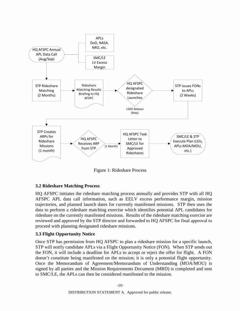
3.1 Auxiliary Payload Selection and Rideshare Assessment STP is the designated initial contact for all APLs seeking launch opportunities on DoD missions. Candidate APLs, and/or their sponsoring organizations, should participate in the annual HQ AFSPC APL data call process and submit the basic information on their requirements as defined in the data call (see Figure 1: Rideshare Process). Candidate APLs must coordinate with STP to ensure adequate performance and compatibility between the PPL and APLs. In this capacity, STP will facilitate relationships between appropriate PPL program offices and APL customers. SMC/LE and STP will identify EELV excess performance margin and useful mission trajectories among manifested missions, and prioritize a list of the opportunities that should be targeted for rideshare missions. Figure 1 describes the APL to mission matching and APL approval for manifesting process.
-10-
DISTRIBUTION STATEMENT A. Approved for public release.
STP Rideshare Matching
(2 Months)
HQ AFSPC Annual APL Data Call
(Aug/Sep)
Rideshare Matching Results
Briefing to HQ AFSPC
HQ AFSPC designated Rideshare Launches
STP issues FONs to APLs
(2 Weeks)
APLsDoD, NASA,
NRO, etc.
SMC/LELV Excess
Margin
HQ AFSPC Receives ARP
from STP
HQ AFSPC Task Letter to
SMC/LE for Approved Rideshares
STP Creates ARPs for
Rideshare Missions
(1 month)
SMC/LE & STP Execute Plan (LEIs, APLs MOA/MOU,
etc.)
LSDO Release(May)
(1 Month)
Figure 1: Rideshare Process
3.2 Rideshare Matching Process HQ AFSPC initiates the rideshare matching process annually and provides STP with all HQ AFSPC APL data call information, such as EELV excess performance margin, mission trajectories, and planned launch dates for currently manifested missions. STP then uses the data to perform a rideshare matching exercise which identifies potential APL candidates for rideshare on the currently manifested missions. Results of the rideshare matching exercise are reviewed and approved by the STP director and forwarded to HQ AFSPC for final approval to proceed with planning designated rideshare missions.
3.3 Flight Opportunity Notice Once STP has permission from HQ AFSPC to plan a rideshare mission for a specific launch, STP will notify candidate APLs via a Flight Opportunity Notice (FON). When STP sends out the FON, it will include a deadline for APLs to accept or reject the offer for flight. A FON doesn’t constitute being manifested on the mission; it is only a potential flight opportunity. Once the Memorandum of Agreement/Memorandum of Understanding (MOA/MOU) is signed by all parties and the Mission Requirements Document (MRD) is completed and sent to SMC/LE, the APLs can then be considered manifested to the mission.

-11-
DISTRIBUTION STATEMENT A. Approved for public release.
3.4 APL Recommendation Plan STP will submit an APL Recommendation Plan (ARP) to HQ AFSPC listing all the APLs, APL size and mass, and orbit requirements for the rideshare mission. Some of the APL information may not be mature, but should meet the initial requirements for HQ AFSPC to review. If HQ AFSPC approves the ARP for the mission, HQ AFSPC will issue a tasking letter to SMC/LE to designate the mission as a Rideshare and identify the number and types of APLs to include on the manifest.
3.5 Leading Edge Integration (LEI) After the ARP is approved and tasking letter issued, STP will work with SMC/LE to build an acquisition package to accomplish a Leading Edge Integration (LEI) effort. The package will include the primary payload name, projected launch date, potential orbit(s), and any other top-level mission elements or constraints required to determine the feasibility of the candidate APL mission. SMC/LE will then contract the LVC(s) to conduct an LEI study to determine the compatibility of the PPL and the APL(s). Mission unique requirements (non-standard services) needed by APLs will also be determined and defined in this compatibility study.
3.6 APL Manifesting STP will initiate a MOA, if transfer of funding is required, or a MOU with each APL to document the roles and responsibilities of the STP Program Office and the APL’s organization and clearly delineate necessary support required of each organization to ensure successful mission execution. STP will create a MRD to document the mission requirements of all the APLs for SMC/LE to put on contract with the LVC(s) for LEI purposes. Once the MOA/MOU is signed by all parties and the MRD is completed and sent to SMC/LE, the APLs can then be considered manifested to the mission. The APLs must satisfy specific compliance review success criteria in order to remain manifested on the EELV mission. In the event that a manifested APL fails to meet the minimum criteria required to remain manifested on the EELV mission, the slot may be given to another APL or the APLP may be required to replace the APL with a flight-qualified mass simulator.
4.0 RIDESHARE EXECUTION PROCESS 4.1 Do-No-Harm Given the increasing number of US Air Force launch missions that include rideshare, the need for an established method of assessing mission risks across programs with differing levels of risk tolerance has become essential. The mission risks cover not only technical but also cost and schedule of the mission. STP developed a method for Rideshare Mission Assurance (RMA) that seeks to allow missions with different risk tolerances to fly together on a single launch, while shielding each mission from external risks to on-orbit performance. The RMA process focuses on ensuring that no APLs on a rideshare mission will negatively affect the on-orbit functionality of the primary payload or any other payload.
RMA is a process that allows all mission partners to accept self-induced or programmatic risks (termed “payload mission assurance risks”) without having to evaluate any circumstances beyond their direct control. RMA is not a “classic” mission assurance practice, as it does NOT take into account the on-orbit functionality of the payload being assessed, and only assures that

-12-
DISTRIBUTION STATEMENT A. Approved for public release.
it will “Do-No-Harm” (DNH) to any mission partners. The RMA approach allows multiple programs with vastly different risk tolerances to share a single launch. RMA is especially useful when the organization responsible for certifying the entire mission does not have a Mission Assurance role for all of the spacecraft on the mission (e.g. SMC/CC will certify EELV missions that include spacecraft from non-SMC organizations). The RMA process does not change the basic risk identification and capture process used by SMC. The RMA/DNH process allows Mission Managers to divide all payload related mission risks into two categories: Payload Mission Success and Safety of Flight. Mission success risks only affect the post-LV delivery on-orbit functionality of an individual payload and are accepted by each individual payload's Risk Acceptance Authority. Safety of Flight (generally considered space safety) risks pose a threat from the start of launch processing until mission completion, and must be accepted by the mission team as a whole. As part of the RMA process, each agency provides its own Mission Assurance and certification letter for their own spacecraft. Verification artifacts are provided with the certification letter to provide inputs to the DNH analysis. SMC, with Aerospace support, provides the DNH mission assurance assessment for the integrated payload stack. SMC/CC will provide launch approval for the mission as a whole.
4.2 Rideshare Integration RSS integration schedules are developed and adjusted as necessary to maintain compatibility with the PPL’s integration schedule. APLs may not impact the PPL’s schedule without approval by AFSPC/A2/3/6. AFSPC/A2/3/6 will coordinate schedule impacts with mission stakeholders prior to approval. If the APL poses unacceptable schedule risk to the PPL’s integration schedule, the risk may be mitigated by de-manifesting the APL and offering the rideshare slot to a different APL. If no suitable replacement can be found, the APL customer may be required to replace its APL with a flight-qualified mass simulator. Details regarding typical rideshare integration meetings and milestones associated with RSS are given in the following subsections and Table 4-1.
APLs should contact SMC/LE and STP for the currently available interfaces offered by the LVCs so that associated mission unique costs can be avoided. The LVC will be responsible for ensuring compatibility of the PPL requirements with the APL requirements; and the PPL requirements take precedence in the event of a conflict. Both the LVC and the APLP(s) will be responsible for providing evidence verifying they meet each of their assigned interface requirements.
4.3 Integration Meetings and Compliance Reviews RSS includes meetings and reviews with SMC/LE, the PPLP, APLP, STP, and other necessary government offices. These include telecons, Technical Interchange Meetings (TIMs), and Management Working Groups as needed. The Mission Kickoff meeting is nominally at L-24 months. Following this will be an ICD Review at approximately L-18 months where interface requirements and verification plans will be finalized. At a minimum, one Ground Operations Working Group will be conducted to familiarize the APLs with the launch site and ground interfaces to be used for the rideshare service. Immediately prior to APL arrival at the processing facility, a Ground Operations Readiness Review will be held to review ground operations plans and schedules to assess launch site readiness to receive the APL(s).
-13-
DISTRIBUTION STATEMENT A. Approved for public release.
The LVC will conduct reviews to ensure that PPL and APL requirements are understood and defined correctly, and that LV integration, analyses and mission designs meet mission requirements. The LVC prepares and presents reviews with participation from stakeholders.
APLs will be subject to three compliance reviews at L-18, L-12, and L-6 months. The reviews will focus on APL readiness and the quality and timeliness of APL mission documentation. APLs must satisfy specific compliance review success criteria in order to remain manifested on the EELV mission.
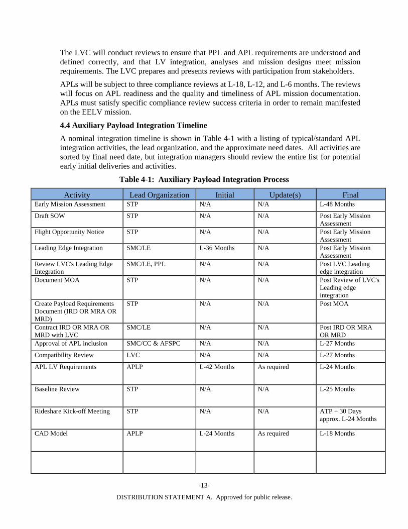
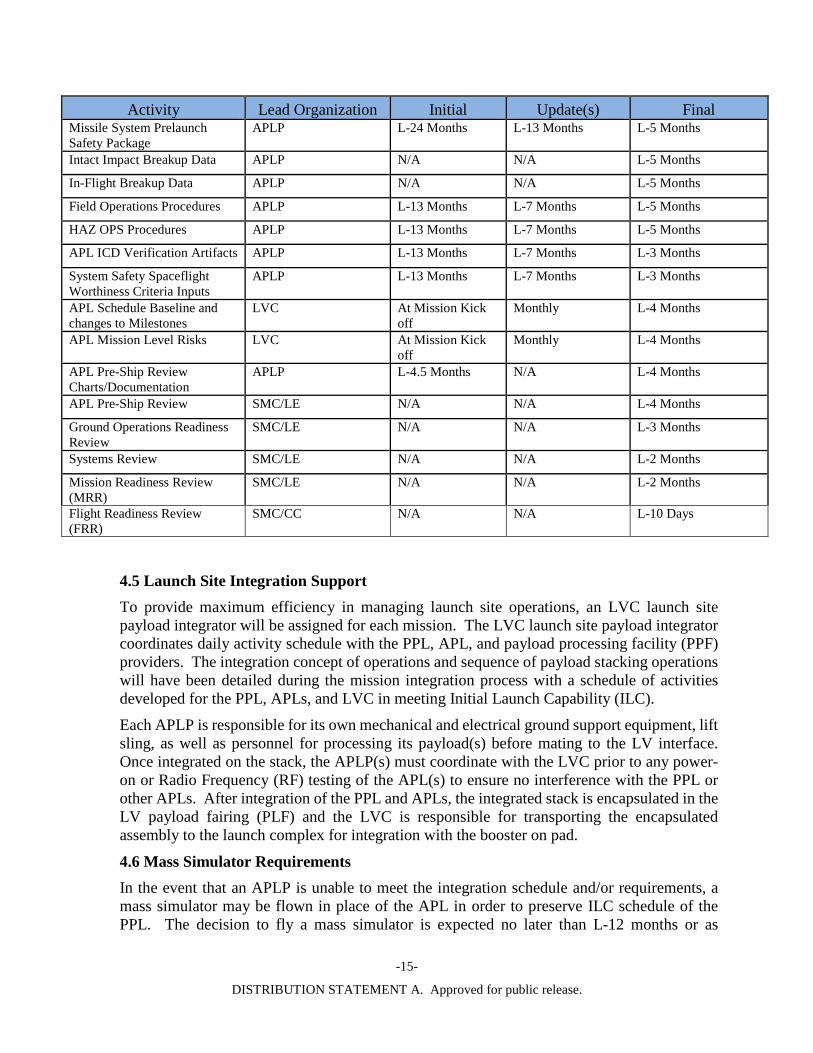
4.4 Auxiliary Payload Integration Timeline A nominal integration timeline is shown in Table 4-1 with a listing of typical/standard APL integration activities, the lead organization, and the approximate need dates. All activities are sorted by final need date, but integration managers should review the entire list for potential early initial deliveries and activities.
Table 4-1: Auxiliary Payload Integration Process
Activity Lead Organization Initial Update(s) Final Early Mission Assessment STP N/A N/A L-48 Months
Draft SOW STP N/A N/A Post Early Mission Assessment
Flight Opportunity Notice STP N/A N/A Post Early Mission Assessment
Leading Edge Integration SMC/LE L-36 Months N/A Post Early Mission Assessment
Review LVC's Leading Edge Integration
SMC/LE, PPL N/A N/A Post LVC Leading edge integration
Document MOA STP N/A N/A Post Review of LVC's Leading edge integration
Create Payload Requirements Document (IRD OR MRA OR MRD)
STP N/A N/A Post MOA
Contract IRD OR MRA OR MRD with LVC
SMC/LE N/A N/A Post IRD OR MRA OR MRD
Approval of APL inclusion SMC/CC & AFSPC N/A N/A L-27 Months
Compatibility Review LVC N/A N/A L-27 Months
APL LV Requirements APLP L-42 Months As required L-24 Months
Baseline Review STP N/A N/A L-25 Months
Rideshare Kick-off Meeting STP N/A N/A ATP + 30 Days approx. L-24 Months
CAD Model APLP L-24 Months As required L-18 Months
-14-
DISTRIBUTION STATEMENT A. Approved for public release.
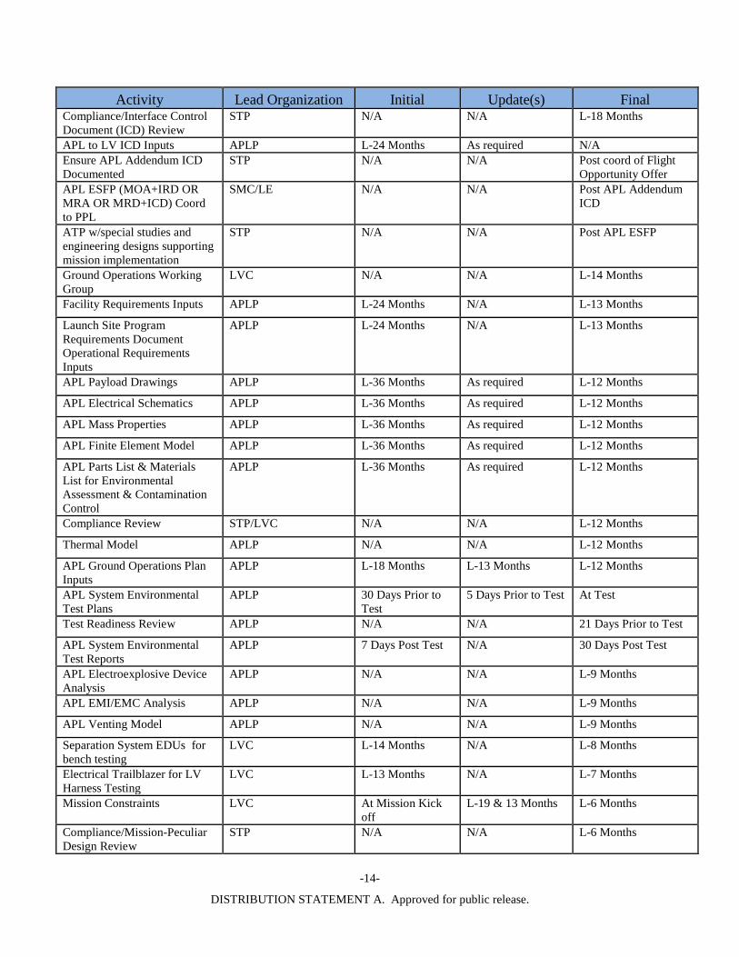
Activity Lead Organization Initial Update(s) Final Compliance/Interface Control Document (ICD) Review
STP N/A N/A L-18 Months
APL to LV ICD Inputs APLP L-24 Months As required N/A Ensure APL Addendum ICD Documented
STP N/A N/A Post coord of Flight Opportunity Offer
APL ESFP (MOA+IRD OR MRA OR MRD+ICD) Coord to PPL
SMC/LE N/A N/A Post APL Addendum ICD
ATP w/special studies and engineering designs supporting mission implementation
STP N/A N/A Post APL ESFP
Ground Operations Working Group
LVC N/A N/A L-14 Months
Facility Requirements Inputs APLP L-24 Months N/A L-13 Months
Launch Site Program Requirements Document Operational Requirements Inputs
APLP L-24 Months N/A L-13 Months
APL Payload Drawings APLP L-36 Months As required L-12 Months
APL Electrical Schematics APLP L-36 Months As required L-12 Months
APL Mass Properties APLP L-36 Months As required L-12 Months
APL Finite Element Model APLP L-36 Months As required L-12 Months
APL Parts List & Materials List for Environmental Assessment & Contamination Control
APLP L-36 Months As required L-12 Months
Compliance Review STP/LVC N/A N/A L-12 Months
Thermal Model APLP N/A N/A L-12 Months
APL Ground Operations Plan Inputs
APLP L-18 Months L-13 Months L-12 Months
APL System Environmental Test Plans
APLP 30 Days Prior to Test
5 Days Prior to Test At Test
Test Readiness Review APLP N/A N/A 21 Days Prior to Test
APL System Environmental Test Reports
APLP 7 Days Post Test N/A 30 Days Post Test
APL Electroexplosive Device Analysis
APLP N/A N/A L-9 Months
APL EMI/EMC Analysis APLP N/A N/A L-9 Months
APL Venting Model APLP N/A N/A L-9 Months
Separation System EDUs for bench testing
LVC L-14 Months N/A L-8 Months
Electrical Trailblazer for LV Harness Testing
LVC L-13 Months N/A L-7 Months
Mission Constraints LVC At Mission Kick off
L-19 & 13 Months L-6 Months
Compliance/Mission-Peculiar Design Review
STP N/A N/A L-6 Months
-15-
DISTRIBUTION STATEMENT A. Approved for public release.
Activity Lead Organization Initial Update(s) Final Missile System Prelaunch Safety Package
APLP L-24 Months L-13 Months L-5 Months
Intact Impact Breakup Data APLP N/A N/A L-5 Months
In-Flight Breakup Data APLP N/A N/A L-5 Months
Field Operations Procedures APLP L-13 Months L-7 Months L-5 Months
HAZ OPS Procedures APLP L-13 Months L-7 Months L-5 Months
APL ICD Verification Artifacts APLP L-13 Months L-7 Months L-3 Months
System Safety Spaceflight Worthiness Criteria Inputs
APLP L-13 Months L-7 Months L-3 Months
APL Schedule Baseline and changes to Milestones
LVC At Mission Kick off
Monthly L-4 Months
APL Mission Level Risks LVC At Mission Kick off
Monthly L-4 Months
APL Pre-Ship Review Charts/Documentation
APLP L-4.5 Months N/A L-4 Months
APL Pre-Ship Review SMC/LE N/A N/A L-4 Months
Ground Operations Readiness Review
SMC/LE N/A N/A L-3 Months
Systems Review SMC/LE N/A N/A L-2 Months
Mission Readiness Review (MRR)
SMC/LE N/A N/A L-2 Months
Flight Readiness Review (FRR)
SMC/CC N/A N/A L-10 Days
4.5 Launch Site Integration Support To provide maximum efficiency in managing launch site operations, an LVC launch site payload integrator will be assigned for each mission. The LVC launch site payload integrator coordinates daily activity schedule with the PPL, APL, and payload processing facility (PPF) providers. The integration concept of operations and sequence of payload stacking operations will have been detailed during the mission integration process with a schedule of activities developed for the PPL, APLs, and LVC in meeting Initial Launch Capability (ILC).
Each APLP is responsible for its own mechanical and electrical ground support equipment, lift sling, as well as personnel for processing its payload(s) before mating to the LV interface. Once integrated on the stack, the APLP(s) must coordinate with the LVC prior to any power-on or Radio Frequency (RF) testing of the APL(s) to ensure no interference with the PPL or other APLs. After integration of the PPL and APLs, the integrated stack is encapsulated in the LV payload fairing (PLF) and the LVC is responsible for transporting the encapsulated assembly to the launch complex for integration with the booster on pad.
4.6 Mass Simulator Requirements In the event that an APLP is unable to meet the integration schedule and/or requirements, a mass simulator may be flown in place of the APL in order to preserve ILC schedule of the PPL. The decision to fly a mass simulator is expected no later than L-12 months or as

-16-
DISTRIBUTION STATEMENT A. Approved for public release.
determined by the LVC to preclude impact to mission analyses that could affect schedule. The decision authority over the requirement to fly a mass simulator, to ensure no impact to integrated analyses and ultimately mission schedule, is shared between SMC/LE, STP, and AFSPC/A2/3/6. The mass simulator will be required to meet the same mass and center of gravity (cg) requirements levied on the APL as well as a subset of the structural and environmental requirements, which will be specified in the ICD. The APLPs are responsible for mass simulator design, build, and verification to the same schedule dates as the actual APL.
In lieu of mass simulator, the APLP can substitute another payload provided that there is no impact to overall mission risks including technical, cost, and schedule. The substituted payload must be approved by all stakeholders (other APLPs, PPLP, LVC, STP, LE, etc.)
4.8 Facilities and Processing The PPL and APLs process, check out and ready their payloads for launch in separate payload processing facilities (PPFs). The LVC processes the booster in their own facility near the launch pad, and prepares the fairing and adapter in a facility that is convenient for integrating the PPL and APLs onto the integrated stack for fairing encapsulation. Ideally the PPL, APL, and LVC personnel perform these activities independently before encapsulation in the same processing facility to facilitate the integration of the stack. Nominally, the APL should arrive at the processing facility at L-60 days to begin a 30-day processing period but it depends on the individual APL. The APL should be ready for APL/rideshare mate by L-30 days or as determined by the team (LVC/PPL/APLs) during mission integration process.
4.9 Access to Auxiliary Payloads – Timelines RSS does not provide for access to the APL on a regular basis once it has been integrated to the LV and encapsulated in the PLF. Access to the APL may be provided on a limited basis if requested by the APLP. The APL will be capable of withstanding extended durations in the rideshare mating facility and launch complex facilities without access and up to 16 days without battery charging or monitoring. No access is allowed, including the umbilical, after PLF closeout and during transport operations.
4.10 Payload Battery Charging and Monitoring Restrictions Battery charging procedures will need to meet applicable Range Safety regulations documented in AFSPCMAN 91-710, including restrictions during hazardous operations. For further battery charging capabilities and restrictions see the APL class details.
4.11 Aborts and Recycles The LV may need to conduct multiple launch attempts, during which the APL is not accessible. There is no physical access to the APL until after contingency stand down plans are made and even then only as an additional contingency event negotiated with the PPL, LE, STP and LVC.
The APL will not be polled during the launch sequence to cause an LV abort or LV recycle.
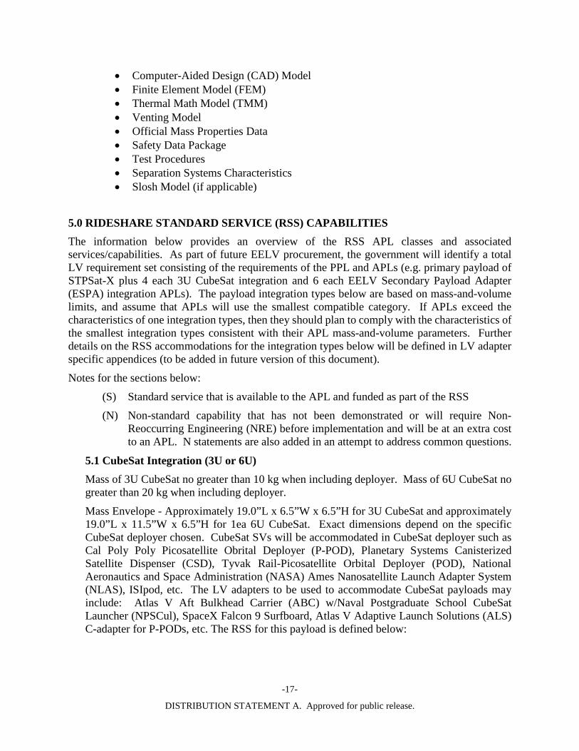
4.12 Auxiliary Payload Data Requirements As part of the RSS process, APLs will be required to provide various data to the government team and LVC in support of mission analyses. Some examples of data requirements are included below, but not limited to
-17-
DISTRIBUTION STATEMENT A. Approved for public release.
• Computer-Aided Design (CAD) Model • Finite Element Model (FEM) • Thermal Math Model (TMM) • Venting Model • Official Mass Properties Data • Safety Data Package • Test Procedures • Separation Systems Characteristics • Slosh Model (if applicable)
5.0 RIDESHARE STANDARD SERVICE (RSS) CAPABILITIES The information below provides an overview of the RSS APL classes and associated services/capabilities. As part of future EELV procurement, the government will identify a total LV requirement set consisting of the requirements of the PPL and APLs (e.g. primary payload of STPSat-X plus 4 each 3U CubeSat integration and 6 each EELV Secondary Payload Adapter (ESPA) integration APLs). The payload integration types below are based on mass-and-volume limits, and assume that APLs will use the smallest compatible category. If APLs exceed the characteristics of one integration types, then they should plan to comply with the characteristics of the smallest integration types consistent with their APL mass-and-volume parameters. Further details on the RSS accommodations for the integration types below will be defined in LV adapter specific appendices (to be added in future version of this document).
Notes for the sections below:
(S) Standard service that is available to the APL and funded as part of the RSS
(N) Non-standard capability that has not been demonstrated or will require Non-Reoccurring Engineering (NRE) before implementation and will be at an extra cost to an APL. N statements are also added in an attempt to address common questions.
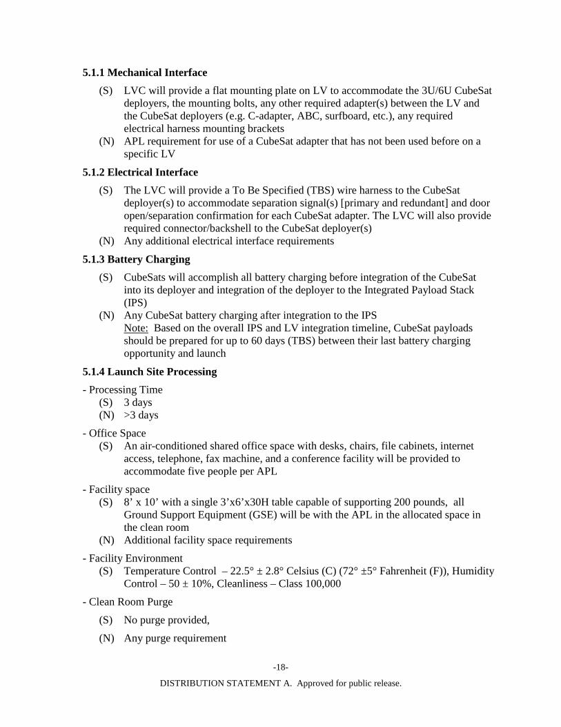
5.1 CubeSat Integration (3U or 6U) Mass of 3U CubeSat no greater than 10 kg when including deployer. Mass of 6U CubeSat no greater than 20 kg when including deployer.
Mass Envelope - Approximately 19.0”L x 6.5”W x 6.5”H for 3U CubeSat and approximately 19.0”L x 11.5”W x 6.5”H for 1ea 6U CubeSat. Exact dimensions depend on the specific CubeSat deployer chosen. CubeSat SVs will be accommodated in CubeSat deployer such as Cal Poly Poly Picosatellite Obrital Deployer (P-POD), Planetary Systems Canisterized Satellite Dispenser (CSD), Tyvak Rail-Picosatellite Orbital Deployer (POD), National Aeronautics and Space Administration (NASA) Ames Nanosatellite Launch Adapter System (NLAS), ISIpod, etc. The LV adapters to be used to accommodate CubeSat payloads may include: Atlas V Aft Bulkhead Carrier (ABC) w/Naval Postgraduate School CubeSat Launcher (NPSCul), SpaceX Falcon 9 Surfboard, Atlas V Adaptive Launch Solutions (ALS) C-adapter for P-PODs, etc. The RSS for this payload is defined below:
-18-
DISTRIBUTION STATEMENT A. Approved for public release.
5.1.1 Mechanical Interface (S) LVC will provide a flat mounting plate on LV to accommodate the 3U/6U CubeSat
deployers, the mounting bolts, any other required adapter(s) between the LV and the CubeSat deployers (e.g. C-adapter, ABC, surfboard, etc.), any required electrical harness mounting brackets
(N) APL requirement for use of a CubeSat adapter that has not been used before on a specific LV
5.1.2 Electrical Interface (S) The LVC will provide a To Be Specified (TBS) wire harness to the CubeSat
deployer(s) to accommodate separation signal(s) [primary and redundant] and door open/separation confirmation for each CubeSat adapter. The LVC will also provide required connector/backshell to the CubeSat deployer(s)
(N) Any additional electrical interface requirements
5.1.3 Battery Charging (S) CubeSats will accomplish all battery charging before integration of the CubeSat
into its deployer and integration of the deployer to the Integrated Payload Stack (IPS)
(N) Any CubeSat battery charging after integration to the IPS Note: Based on the overall IPS and LV integration timeline, CubeSat payloads
should be prepared for up to 60 days (TBS) between their last battery charging opportunity and launch
5.1.4 Launch Site Processing - Processing Time
(S) 3 days (N) >3 days
- Office Space (S) An air-conditioned shared office space with desks, chairs, file cabinets, internet
access, telephone, fax machine, and a conference facility will be provided to accommodate five people per APL
- Facility space (S) 8’ x 10’ with a single 3’x6’x30H table capable of supporting 200 pounds, all
Ground Support Equipment (GSE) will be with the APL in the allocated space in the clean room
(N) Additional facility space requirements
- Facility Environment (S) Temperature Control – 22.5° ± 2.8° Celsius (C) (72° ±5° Fahrenheit (F)), Humidity
Control – 50 ± 10%, Cleanliness – Class 100,000
- Clean Room Purge
(S) No purge provided,
(N) Any purge requirement
-19-
DISTRIBUTION STATEMENT A. Approved for public release.
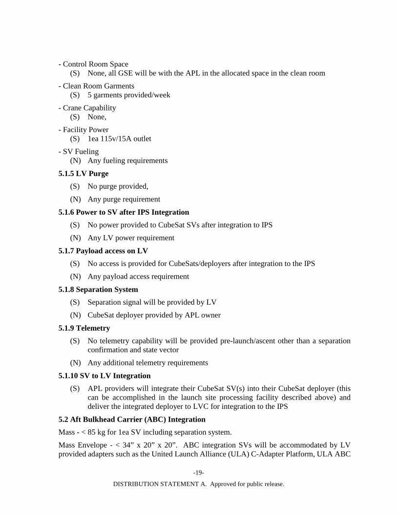
- Control Room Space (S) None, all GSE will be with the APL in the allocated space in the clean room
- Clean Room Garments (S) 5 garments provided/week
- Crane Capability (S) None,
- Facility Power (S) 1ea 115v/15A outlet
- SV Fueling (N) Any fueling requirements
5.1.5 LV Purge (S) No purge provided,
(N) Any purge requirement
5.1.6 Power to SV after IPS Integration (S) No power provided to CubeSat SVs after integration to IPS
(N) Any LV power requirement
5.1.7 Payload access on LV (S) No access is provided for CubeSats/deployers after integration to the IPS
(N) Any payload access requirement
5.1.8 Separation System (S) Separation signal will be provided by LV
(N) CubeSat deployer provided by APL owner
5.1.9 Telemetry (S) No telemetry capability will be provided pre-launch/ascent other than a separation
confirmation and state vector
(N) Any additional telemetry requirements
5.1.10 SV to LV Integration (S) APL providers will integrate their CubeSat SV(s) into their CubeSat deployer (this
can be accomplished in the launch site processing facility described above) and deliver the integrated deployer to LVC for integration to the IPS
5.2 Aft Bulkhead Carrier (ABC) Integration Mass - < 85 kg for 1ea SV including separation system.
Mass Envelope - < 34” x 20” x 20”. ABC integration SVs will be accommodated by LV provided adapters such as the United Launch Alliance (ULA) C-Adapter Platform, ULA ABC
-20-
DISTRIBUTION STATEMENT A. Approved for public release.
Johns Hopkins University/Applied Physics Laboratory (JHU/APL) Express Platform, ESPA, ALS AQUILA, SHERPA, etc. If the APL is an encapsulated payload/deployer (e.g. 12U CubeSat deployer) the APL providers shall deliver the APL(s) already integrated into appropriate deployer.
5.2.1 Mechanical Interface (S) The hardware to be provided as part of an ABC integration Mission Kit includes:
LV ABC integration Adapter to mount APL(s), applicable spacers (e.g. C-adapter) between LV and ABC integration adapter; ABC integration separation system(s), APL servicing, separation command and separation detection wiring harnesses, brackets, and connectors.
(N) APL requirement for use of an ABC integration adapter that has not been used before on a specific LV
5.2.2 Electrical Interface (S) ABC Users Guide (see para 1.3 for document Reference) defines the standard
electrical interface for both separating and non-separating (e.g., CubeSat deployer) payloads, LVC will provide required connectors/backshells required for this interface. No power will be provided to the ABC payload after T-0 seconds (i.e. during ascent)
(N) Additional electrical interface requirements that require significant LV NRE to implement.
5.2.3 Battery charging (S) Battery charging for ABC integration payloads will not be provided for the period
when the APL is being integrated to the IPS or when the IPS is being integrated to the LV. Battery charging for ABC integration payloads can be provided after the IPS has been integrated to the LV through the T-0 umbilical until launch. Battery charging will be accommodated within the limits of the electrical interface. The APL will be required to meet battery charge monitoring requirements per AFPSCMAN 91-710. APL monitoring of the charge activity will be required to avoid generation of RF emissions that may affect nearby hardware.
(N) Additional battery charging requirements that require significant NRE to implement.
5.2.4 Launch Site Processing - Processing Time
(S) 7 days,
- Office Space (S) An air-conditioned shared office space with desks, chairs, file cabinets, internet
access, telephone, fax machine, and a conference facility will be provided to accommodate five people per APL.
- Facility Space (S) 10’ x 15’ with a single 3’x6’x30H table capable of supporting 200 pounds, all GSE
will be with the APL in the allocated space in the clean room;
- Facility Environment

-21-
DISTRIBUTION STATEMENT A. Approved for public release.
(S) Temperature Control – 22.5° ± 2.8° C (72° ±5° F), Humidity Control – 50 ± 10%, Cleanliness – Class 100,000,
- Control Room Space (S) None, all GSE will be with the APL in the allocated space in the clean room
- Clean Room Purge
(S) No purge provided
(N) Any purge requirement - Clean Room Garments
(S) 5 garments provided/week - Crane capability:
(S) None
- Facility Power: (S) 4ea 115v/15A outlet,
- SV Fueling (S) Fueling of SV with propellants (e.g high pressure gas, green propellant [e.g. AF-
M315E, LMP-103S], MMH/nitrogen tetroxide, etc.) provided by SV or LV provider
5.2.5 LV Purge (S) No purge provided
(N) Any purge requirement
5.2.6 Power to SV after IPS Integration (S) No power provided to APL between the time the APL is integrated to the IPS and the
IPS is integrated to the LV. After IPS is integrated to LV power can be provided to the APL using the T-0 umbilical. No APL power will be provided after T-0 seconds.
(N) Additional power requirements that require significant LV NRE to implement
5.2.7 Payload access on LV (S) No access is provided to the APL after integration to the IPS
(N) Payload access requirements that require additional fairing doors, other fairing access equipment, or that require significant LV NRE to implement
5.2.8 Separation System (S) Separation signal will be provided by LV
(N) Separation system provided by the APL owner
5.2.9 Telemetry (S) APLs can collect battery monitoring or other telemetry up through T-0 seconds using
the standard electrical interface, APL GSE equipment location and other requirements will be negotiated with the LV contractor and primary payload. APLs will be provided a separation confirmation and state vector
-22-
DISTRIBUTION STATEMENT A. Approved for public release.
(N) Additional APL telemetry requirements that require significant LV contractor NRE to implement
5.2.10 SV to LV Integration (S) LV contractor will integrate the APL to the IPS and the IPS to the LV
(N) APL requests to accomplish integration of APL to IPS
5.3 ESPA Integration Mass - <180 kg for SV including separation system.
Mass Envelope - <24” x 28” x 38”. ESPA integration SVs will be accommodated by LV provided adapters such as: Propulsive ESPA, ULA C-Adapter Platform, JHU/APL Express Platform, ESPA, ALS AQUILA SHERPA, etc. The hardware to be provided as part of an ESPA integration Mission Kit includes: LV ESPA integration Adapter to mount APL(s), applicable spacers (e.g. C-adapter) between LV and ESPA integration adapter; ESPA integration separation system(s), APL servicing, separation command and separation detection wiring harnesses, brackets, and connectors.
5.3.1 Mechanical Interface (S) The hardware to be provided as part of an ESPA integration Mission Kit includes:
LV to ESPA integration Adapter to mount APL(s), applicable spacers (e.g. C-adapter) between LV and ESPA integration adapter; ESPA integration separation system(s), APL servicing, separation command and separation detection wiring harnesses, brackets, and connectors.
(N) APL requirement for use of an ESPA integration adapter that has not been used before on a specific LV
5.3.2 Electrical Interface (S) The APL electrical interface details will be contained in the LV specific ESPA
integration adapter appendices to be added to the next version of the RUG. The electrical interface for each APL will meet or exceed the following: separation signal(s) [primary and redundant] and separation confirmation; two 15-pin In-Flight Disconnect (IFD) separation connectors used for ground APL servicing functions and LV-monitored separation breakwire loops only. No power will be provided to the ESPA payload after T-0 seconds (i.e. during ascent)
(N) Additional electrical interface requirements that require significant LV NRE to implement.
5.3.3 Battery Charging (S) Battery charging for ESPA integration payloads will not be provided for the period
when the APL is being integrated to the IPS or when the IPS is being integrated to the LV. Battery charging for ESPA integration payloads can be provided after the IPS has been integrated to the LV through the T-0 umbilical until launch. Battery charging will be accommodated within the limits of the electrical interface. APL will required to meet battery charge monitoring requirements per AFPSCMAN 91-710. APL monitoring of the charge activity will be required to avoid generation of RF emissions that may affect nearby hardware.
-23-
DISTRIBUTION STATEMENT A. Approved for public release.
(N) Additional battery charging requirements that require significant LV NRE to implement.
5.3.4 Launch Site Processing - Processing Time:
(S) 10 days per ESPA SV and 30 days total for ESPA+APLs integration,
- Office Space: (S) An air-conditioned shared office space with desks, chairs, file cabinets, internet
access, telephone, fax machine, and a conference facility will be provided to accommodate five people per APL.
- Facility space: (S) 60’ x 50’ x 24’H, to be shared among up to six ESPA integration APLs and
propulsive ESPA (if required), APL GSE to be located in this facility or in control room space.
- Facility Environment: (S) Temperature Control – 22.5° ± 2.8° C (72° ±5° F), Humidity Control – 50 ± 10%,
Cleanliness – Class 100,000,
- Control Room space: (S) 34’ x 24’ x 10’H, to be shared among up to six ESPA integration APLs and
propulsive ESPA (if required),
- Clean room purge
(S) No purge provided,
(N) Additional APL purge requirements that require significant LV contractor NRE to implement
- Clean room garments (S) 5 garments provided/week for each ESPA APL,
- Crane Capability: (S) Crane capacity 25 tons, 73’ hook height
- Facility Power: (S) TBS
- SV Fueling (S) Fueling of SV with propellants (e.g high pressure gas, green propellant [e.g. AF-
M315E, LMP-103S], MMH/nitrogen tetroxide, etc.) provided by SV or LV provider
5.3.5 LV Purge (S) No purge provided,
(N) Additional APL purge requirements that require significant LV contractor NRE to implement
-24-
DISTRIBUTION STATEMENT A. Approved for public release.
5.3.6 Power to SV after IPS integration (S) No power provided to APL between the time the APL is integrated to the IPS and the
IPS is integrated to the LV. After IPS is integrated to LV power can be provided to the APL using the T-0 umbilical. No APL power will be provided after T-0 seconds
5.3.7 Payload access on LV (S) No access is provided for the APL after encapsulation
(N) Payload access requirements that require additional fairing doors, other fairing access equipment, or that require significant LV NRE to implement
5.3.8 Separation System (S) Separation signal will be provided by LV
(N) Separation system provided by the APL owner
5.3.9 Telemetry (S) APLs can collect battery monitoring or other telemetry up through T-0 seconds using
the standard electrical interface in, APL GSE equipment location and other requirements will be negotiated with the LV contractor and primary payload. APLs will be provided a separation confirmation and state vector
(N) Additional APL telemetry requirements that require significant LV contractor NRE to implement
5.3.10 SV to LV Integration (S) LVC will integrate the APL to the IPS and the IPS to the LV
(N) APL requests to accomplish integration of APL to IPS
5.4 ESPA Grande Integration Mass - <320 kg for SV including separation system.
Mass Envelope - <42” x 46” x 56” (5m fairing), <42” x 46” x 38” (4m fairing). ESPA Grande integration SVs will be accommodated by LV provided adapters such as: Propulsive ESPA, ESPA Grande, SpaceX dispenser integration payload ring, super SHERPA, ALS AQUILA, etc. The hardware to be provided as part of an ESPA Grande integration Mission Kit includes: LV ESPA Grande integration Adapter to mount APL(s), applicable spacers (e.g. C-adapter) between LV and ESPA Grande integration adapter; ESPA Grande integration separation system(s), APL servicing, separation command and separation detection wiring harnesses, brackets, and connectors.
5.4.1 Mechanical Interface (S) The hardware to be provided as part of an ESPA Grande integration Mission Kit
includes: LV to ESPA Grande integration Adapter to mount APL(s), applicable spacers (e.g. C-adapter) between LV and ESPA Grande integration adapter; ESPA Grande integration separation system(s), APL servicing, separation command and separation detection wiring harnesses, brackets, and connectors.
-25-
DISTRIBUTION STATEMENT A. Approved for public release.
(N) APL requirement for use of an ESPA-Grande integration adapter that has not been used before on a specific LV
5.4.2 Electrical Interface (S) The APL electrical interface details will be contained in the LV specific ESPA-
Grande integration adapter appendices to be added to the next version of the RUG. The electrical interface for each APL will meet or exceed the following: separation signal(s) [primary and redundant] and separation confirmation; two 15-pin IFD separation connectors used for ground APL servicing functions and LV-monitored separation breakwire loops only. No power will be provided to the ESPA-Grande payload after T-0 seconds (i.e. during ascent)
(N) Additional electrical interface requirements that require significant LV NRE to implement.
5.4.3 Battery charging (S) Battery charging for ESPA-Grande integration payloads will not be provided for the
period when the APL is being integrated to the IPS or when the IPS is being integrated to the LV. Battery charging for ESPA-Grande integration payloads can be provided after the IPS has been integrated to the LV through the T-0 umbilical until launch. Battery charging will be accommodated within the limits of the electrical interface. APL will required to meet battery charge monitoring requirements per AFPSCMAN 91-710. APL monitoring of the charge activity will be required to avoid generation of RF emissions that may affect nearby hardware
(N) Additional battery charging requirements that require significant LV NRE to implement
5.4.4 Launch Site Processing - Processing Time
(S) 10 days per ESPA-Grande SV and 30 days total for ESPA-Grande +APLs integration,
- Office Space (S) An air-conditioned shared office space with desks, chairs, file cabinets, internet
access, telephone, fax machine, and a conference facility will be provided to accommodate five people per APL.
- Facility space (S) 60’ x 50’ x 24’H, to be shared among up to six ESPA-Grande integration APLs and
propulsive ESPA-Grande (if required), APL GSE to be located in this facility or in control room space.
- Facility Environment (S) Temperature Control – 22.5° ± 2.8° C (72° ±5° F), Humidity Control – 50 ± 10%,
Cleanliness – Class 100,000
- Control Room space (S) 34’ x 24’ x 10’H, to be shared among up to six ESPA-Grande integration APLs and
propulsive ESPA-Grande (if required)
-26-
DISTRIBUTION STATEMENT A. Approved for public release.
- Clean Room Purge
(S) No purge provided
(N) Additional APL purge requirements that require significant LV contractor NRE to implement
- Clean Room Garments: (S) 5 garments provided/week for each ESPA-Grande APL
- Crane Capability
(S) Crane capacity 25 tons, 73’ hook height
- Facility Power (S) TBS
- SV Fueling (S) Fueling of SV with propellants (e.g high pressure gas, green propellant [e.g. AF-
M315E, LMP-103S], MMH/nitrogen tetroxide, etc.) provided by SV or LV provider
5.4.5 LV Purge (S) No purge provided
(N) Additional APL purge requirements that require significant LV contractor NRE to implement
5.4.6 Power to SV after IPS Integration (S) No power provided to APL between the time the APL is integrated to the IPS and the
IPS is integrated to the LV. After IPS is integrated to LV power can be provided to the APL using the T-0 umbilical. No APL power will be provided after T-0 seconds.
(N) Additional power requirements that require significant LV NRE to implement
5.4.7 Payload access on LV (S) No access is provided for the APL after faring encapsulation,
(N) Payload access requirements that require additional fairing doors, other fairing access equipment, or that require significant LV NRE to implement
5.4.8 Separation System (S) Separation signal will be provided by LV
(N) Separation system provided by the APL owner
5.4.9 Telemetry (S) APLs can collect battery monitoring or other telemetry up through T-0 seconds using
the standard electrical interface, APL GSE equipment location and other requirements will be negotiated with the LV contractor and primary payload. APLs will be provided a separation confirmation and state vector.
(N) Additional APL telemetry requirements that require significant LV contractor NRE to implement

-27-
DISTRIBUTION STATEMENT A. Approved for public release.
5.4.10 SV to LV Integration (S) LV contractor will integrate the APL to the IPS and the IPS to the LV
(N) APL requests to accomplish integration of APL to IPS
5.5 A-Deck integration Mass - <1000 kg.
Mass Envelope - <56”dia x 60”H. A-Deck integration SVs will be accommodated by LV provided adapters such as: ALS AQUILA, etc. The hardware to be provided as part of an A-Deck integration Mission Kit includes: LV A-Deck integration Adapter to mount the APL, applicable spacers (e.g. C-adapter) between LV and A-Deck integration adapter; A-Deck integration separation system(s), APL servicing, separation command and separation detection wiring harnesses, brackets, and connectors.
5.5.1 Mechanical Interface (S) The hardware to be provided as part of an A-Deck integration Mission Kit includes:
LV to A-Deck integration Adapter to mount APL(s), applicable spacers (e.g. C-adapter) between LV and A-Deck integration adapter; A-Deck integration separation system(s), APL servicing, separation command and separation detection wiring harnesses, brackets, and connectors.
(N) APL requirement for use of an A-Deck integration adapter that has not been used before on a specific LV
5.5.2 Electrical Interface (S) APL electrical interfaces consistent with the EELV SIS. Interface requirements
must be negotiated with the PPL on the mission and the APL will not be able to request services that would impact PPL requirements.
(N) Additional electrical interface requirements that require significant LV NRE to implement.
5.5.3 Battery Charging (S) APL battery charging will be consistent with the EELV SIS. Interface requirements
must be negotiated with the PPL on the mission and the APL will not be able to request battery charging services that would impact PPL requirements.
(N) Additional battery charging requirements that require significant LV NRE to implement.
5.5.4 Launch Site Processing - Processing Time
(S) 14 days
- Office Space (S) An air-conditioned shared office space with desks, chairs, file cabinets, internet
access, telephone, fax machine, and a conference facility will be provided to accommodate five people per APL
- Facility space
-28-
DISTRIBUTION STATEMENT A. Approved for public release.
(S) 60’ x 50’ x 24’H, APL GSE to be located in this facility or in control room space.
- Facility Environment (S) Temperature Control – 22.5° ± 2.8° C (72° ±5° F), Humidity Control – 50 ± 10%,
Cleanliness – Class 100,000
- Control Room space (S) 34’ x 24’ x 10’H,
- Clean room purge
(S) No purge provided,
(N) Additional APL purge requirements that require significant LV contractor NRE to implement
- Clean room Garments (S) 5 garments provided/week
- Crane Capability (S) Crane capacity 25 tons, 73’ hook height
- Facility Power: (S) TBS
- SV Fueling (S) Fueling of SV with propellants (e.g high pressure gas, green propellant [e.g. AF-
M315E, LMP-103S], MMH/nitrogen tetroxide, etc.) provided by SV or LV provider
5.5.5 LV Purge (S) No purge provided,
(N) Additional APL purge requirements that require significant LV contractor NRE to implement
5.5.6 Power to SV after IPS Integration (S) No power provided to APL between the time the APL is integrated to the IPS and the
IPS is integrated to the LV. After IPS is integrated to LV power can be provided to the APL using an EELV SIS compliant electrical interface, no APL power will be provided after T-0 seconds.
(N) Additional power requirements that require significant LV NRE to implement
5.5.7 Payload access on LV (S) No access is provided to the APL after faring encapsulation
(N) Payload access requirements that require additional fairing doors, other fairing access equipment, or that require significant LV NRE to implement
5.5.8 Separation System (S) Separation signal will be provided by LV
(N) Separation system provided by the APL owner
-29-
DISTRIBUTION STATEMENT A. Approved for public release.
5.5.9 Telemetry (S) APLs can collect battery monitoring or other telemetry up through T-0 using EELV
SIS compliant capabilities, APL GSE equipment location and other requirements will be negotiated with the LV contractor and primary payload. APLs will be provided a separation confirmation and state vector.
(N) Additional APL telemetry requirements that require significant LV contractor NRE to implement
5.5.10 SV to LV Integration (S) LVC will integrate the APL to the IPS and the IPS to the LV
(N) APL requests to accomplish integration of APL to IPS
-30-
DISTRIBUTION STATEMENT A. Approved for public release.
6.0 ACRONYMS AND ABBREVIATIONS
° Degrees ABC Aft Bulkhead Carrier AFSPC Air Force Space Command AFSPC/A3 Directorate of Air, Space, and Cyberspace Operations AFSPC/A3SR Spacelift and Range Operations Branch AFSPC/A5 Directorate of Plans and Requirements AFSPCI Air Force Space Command Instruction AFSPCMAN Air Force Space Command Manual ALS Adaptive Launch Solutions APL Auxiliary Payload APLP Auxiliary Payload Provider ASIP Auxiliary Standard Interface Plane ARP APL Recommendation Plan ATP Authority to Proceed C Celsius CAD Computer-Aided Design cg Center of Gravity CLA Coupled Loads Analysis CSD Containerized Satellite Dispenser DNH Do No Harm DoD Department of Defense EELV Evolved Expendable Launch Vehicle EMC Electromagnetic Compatibility EMI Electromagnetic Interference ESFP ESPA Space Flight Package ESPA EELV Secondary Payload Adapter F Fahrenheit FEM Finite Element Analysis FRR Flight Readiness Review ft. Foot/feet ft.2 Square foot/feet FON Flight Opportunity Notice GSE Ground Support Equipment HAZ OPS Hazardous Operations HQ AFSPC Headquarters, Air Force Space Command hr. Hour(s) ICD Interface Control Document IFD In Flight Disconnect ILC Initial Launch Capability
-31-
DISTRIBUTION STATEMENT A. Approved for public release.
IPS Integrated Payload Stack IRD Interface Requirements Document (supplied by APLs) JHU/APL Johns Hopkins University/Applied Physics Laboratory lb. Pound(s) LV Launch Vehicle LVC Launch Vehicle Contractor m Meter(s) MIL-STD Military Standard MOA/MOU Memorandum of Agreement/ Memorandum of Understanding MRA/MRD Mission Requirements Annex/Mission Requirements Document (supplied
by APLs) N/A Not Applicable NASA National Aeronautics and Space Administration NLAS Nanosatellite Launch Adapter System NPSCul Naval Postgraduate School CubeSat launcher NRE Non-Recurring Engineering PLF Payload Fairing PPF Payload Processing Facility PPL Primary Payload PPLP Primary Payload Provider P-POD Poly Picosatellite Orbital Deployer POD Picosatellite Orbital Deployer RF Radio Frequency RMA Rideshare Mission Assurance RSS Rideshare Standard Services RUG Rideshare User’s Guide SIP Standard Interface Plane SIS Standard Interface Specification SMC Space and Missile Systems Center SMC/AD SMC/ Advanced Systems and Development SMC/LE SMC/Launch Systems Enterprise Directorate SPRD System Performance Requirements Document STP Space Test Program SV Space Vehicle TBS To Be Specified TIM Technical Interchange Meeting TMM Thermal Mathematical Mode ULA United Launch Alliance US United States