everything you need to know about marine fuels - fuel/2001 chevron fuels... · 2017-06-24 ·...
TRANSCRIPT

Everything you need to know aboutmarine fuels
Together to serve you betterA Texaco and Chevron Joint Venture Company
This document, and more, is available for download at Martin's Marine Engineering Page - www.dieselduck.net

This document, and more, is available for download at Martin's Marine Engineering Page - www.dieselduck.net
Everything you need toknow about marine fuels
Published by Fuel and Marine Marketing, LLC
Printed in the U.K. March, 2001
Prepared by
Paula J. Spreutels and Monique B. VermeireGhent, Belgium
This document, and more, is available for download at Martin's Marine Engineering Page - www.dieselduck.net
Everything you need to know about marine fuels
This publication was prepared for Fuel and Marine Marketing LLC
(FAMM) by Paula J. Spreutels and Monique B. Vermeire of Heavy Fuels
Technology (HFT), located at the Texaco Technology Ghent Research
Laboratory in Belgium. HFT does exclusive work for FAMM in the area of
fuel technology, with related field support for matters concerning fuel
quality issues. HFT is very active in supporting FAMM on various interna-
tional fuel technical organizations and at industry seminars.
This document, and more, is available for download at Martin's Marine Engineering Page - www.dieselduck.net
I. Introduction . . . . . . . . . . . . . . . . . . . . . . . . . . . . . . . . . . . . . . . . . . . . . . . . . . . . . . . . . . . . . 3
II. Crude oil . . . . . . . . . . . . . . . . . . . . . . . . . . . . . . . . . . . . . . . . . . . . . . . . . . . . . . . . . . 5
1. How is a crude oil field formed? . . . . . . . . . . . . . . . . . . . . . . . . . . . . . . . . . . . . . . . . . . . . 5
2. Composition and classification of crude oil . . . . . . . . . . . . . . . . . . . . . . . . . . . . . . . . . . . 5
3. Crude oil refining and stocks for marine fuel blending . . . . . . . . . . . . . . . . . . . . . . . . . . 5
III. Fuel oil . . . . . . . . . . . . . . . . . . . . . . . . . . . . . . . . . . . . . . . . . . . . . . . . . . . . . . . . . . . . . . . . 9
1. Fuel oil applications . . . . . . . . . . . . . . . . . . . . . . . . . . . . . . . . . . . . . . . . . . . . . . . . . . . . . . 9
2. Fuel specifications . . . . . . . . . . . . . . . . . . . . . . . . . . . . . . . . . . . . . . . . . . . . . . . . . . . . . . . . 9
2a. Significance of the marine fuel properties listed in ISO 8217:1996 . . . . . . . . . . 10
2b. Correspondence of specifications and test methods . . . . . . . . . . . . . . . . . . . . . . 12
3. Test specifications and precision . . . . . . . . . . . . . . . . . . . . . . . . . . . . . . . . . . . . . . . . . . . . 13
4. Onboard fuel oil treatment . . . . . . . . . . . . . . . . . . . . . . . . . . . . . . . . . . . . . . . . . . . . . . . . 13
4a. Conventional cleaning with purifiers/clarifiers . . . . . . . . . . . . . . . . . . . . . . . . . . . 14
4b. Advanced computer driven fuel cleaning system . . . . . . . . . . . . . . . . . . . . . . . . . 15
5. Fuel oil stability and compatibility . . . . . . . . . . . . . . . . . . . . . . . . . . . . . . . . . . . . . . . . . . 16
6. Commingling of fuels . . . . . . . . . . . . . . . . . . . . . . . . . . . . . . . . . . . . . . . . . . . . . . . . . . . . . 16
7. Microbiological contamination . . . . . . . . . . . . . . . . . . . . . . . . . . . . . . . . . . . . . . . . . . . . . 17
8. Fuel contamination in lubricants . . . . . . . . . . . . . . . . . . . . . . . . . . . . . . . . . . . . . . . . . . . 18
9. Used oil in heavy fuel . . . . . . . . . . . . . . . . . . . . . . . . . . . . . . . . . . . . . . . . . . . . . . . . . . . . . 19
Attachments . . . . . . . . . . . . . . . . . . . . . . . . . . . . . . . . . . . . . . . . . . . . . . . . . . . . . . . . . . . . . . . 21
Attachment I: Crude oil refining . . . . . . . . . . . . . . . . . . . . . . . . . . . . . . . . . . . . . . . . . . . . . . . 21
Attachment II: Reproducibility R of marine fuel test methods . . . . . . . . . . . . . . . . . . . . . . 23
Attachment III: Gas turbine fuel requirements . . . . . . . . . . . . . . . . . . . . . . . . . . . . . . . . . . . 24
References . . . . . . . . . . . . . . . . . . . . . . . . . . . . . . . . . . . . . . . . . . . . . . . . . . . . . . . . . . . . . . . . . 25
Reference in this brochure to any specific commercial product, process or service, or the use of any trade, firm, or corporation name is for the information and convenience of the reader,and does not constitute endorsement, recommendation, or favoring by FAMM.
Everything you need to know about marine fuels
Table of Contents
This document, and more, is available for download at Martin's Marine Engineering Page - www.dieselduck.net

Everything you need to know about marine fuels
This document, and more, is available for download at Martin's Marine Engineering Page - www.dieselduck.net
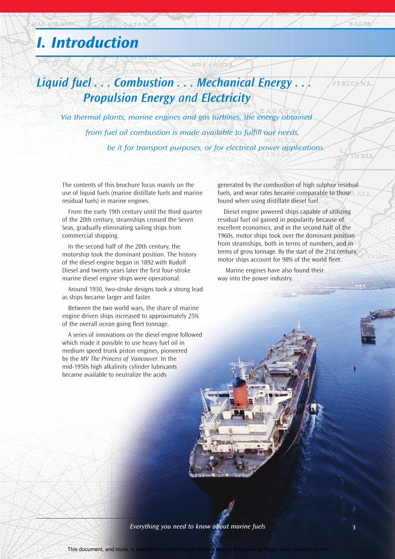
The contents of this brochure focus mainly on theuse of liquid fuels (marine distillate fuels and marineresidual fuels) in marine engines.
From the early 19th century until the third quarterof the 20th century, steamships crossed the SevenSeas, gradually eliminating sailing ships from commercial shipping.
In the second half of the 20th century, the motorship took the dominant position. The historyof the diesel engine began in 1892 with RudolfDiesel and twenty years later the first four-strokemarine diesel engine ships were operational.
Around 1930, two-stroke designs took a strong leadas ships became larger and faster.
Between the two world wars, the share of marineengine driven ships increased to approximately 25%of the overall ocean going fleet tonnage.
A series of innovations on the diesel engine followedwhich made it possible to use heavy fuel oil in medium speed trunk piston engines, pioneeredby the MV The Princess of Vancouver. In themid-1950s high alkalinity cylinder lubricantsbecame available to neutralize the acids
generated by the combustion of high sulphur residualfuels, and wear rates became comparable to thosefound when using distillate diesel fuel.
Diesel engine powered ships capable of utilizingresidual fuel oil gained in popularity because ofexcellent economics, and in the second half of the1960s, motor ships took over the dominant positionfrom steamships, both in terms of numbers, and interms of gross tonnage. By the start of the 21st century,motor ships account for 98% of the world fleet.
Marine engines have also found their way into the power industry.
3
Liquid fuel . . . Combustion . . . Mechanical Energy . . .Propulsion Energy and Electricity
Via thermal plants, marine engines and gas turbines, the energy obtained
from fuel oil combustion is made available to fulfill our needs,
be it for transport purposes, or for electrical power applications.
I. Introduction
Everything you need to know about marine fuels
This document, and more, is available for download at Martin's Marine Engineering Page - www.dieselduck.net

4 Everything you need to know about marine fuels
This document, and more, is available for download at Martin's Marine Engineering Page - www.dieselduck.net
5Everything you need to know about marine fuels
1. HOW IS A CRUDE OIL FIELD FORMED?The generally accepted theory is that crude oil wasformed over millions of years from the remains ofplants and animals that lived in the seas. As theydied, they sank to the seabed, were buried with sandand mud and became an organic-rich layer. Steadily,these layers piled up, tens of meters thick. The sandand mud became sedimentary rock, and the organicremains became droplets of oil and gas. Oil and gaspassed through the porous rock and were eventuallytrapped by an impervious layer of rock, collecting atthe highest point.
The formation of an oil/gas field requires the presence of four geological features:
1) Source rock: contains suitable organic matter, which, under the conditions of heatand pressure, produces hydrocarbons.
2) Reservoir rock: a porous layer of rock inwhich the hydrocarbons are retained
3) Cap rock: a rock or clay, which prevents thehydrocarbons from escaping
4) Trap: a rock formation bent into a dome orbroken by a fault which blocks the escape ofthe hydrocarbons either upwards or sideways.
Most importantly, the above factors have to occur atthe right time, place and in the right order for oil andgas to be formed and trapped. Currently, successfulpetroleum exploration relies on modern techniquessuch as seismic surveying. The fundamental principleof seismic surveying is to initiate a seismic pulse at ornear the earth’s surface and to record the amplitudesand travel times of waves returning to the surfaceafter being reflected or refracted from the interface(s)on one or more layers of rock. Once seismic datahave been acquired they must be processed into aformat suitable for geological interpretation andpetroleum reservoir detection.
2. COMPOSITION AND CLASSIFICATION OF CRUDE OILCrude oil is a mixture of many different hydrocarbonsand small amounts of impurities. The composition ofcrude oil can vary significantly depending on itssource. Crude oils from the same geographical areacan be very different due to different petroleum formation strata.
Different classifications of crude oil exist:1) Based on the type of hydrocarbons:
• paraffinic type crudes• naphtenic type crudes• asphaltenic (aromatic) type crudes
Each crude oil contains the three differenttypes of hydrocarbons, but their relative
percentage may vary widely. Examples of these type of crudes corresponding with a definedgeographical area include paraffinic crude in Saudi Arabia, naphtenic crude in some Nigerianformations and asphaltenic crude in Venezuela.2) Based on their API gravity: The lower the
density of the crude oil, the higher its APIgravity. A higher API gravity means that thecrude contains more valuable lower boilingfractions.
3) Based on the sulphur content: The ever-growing concern for the environment andthe impact on the refining cost calculationsare the base for the third classification:• low sulphur crude• high sulphur crude
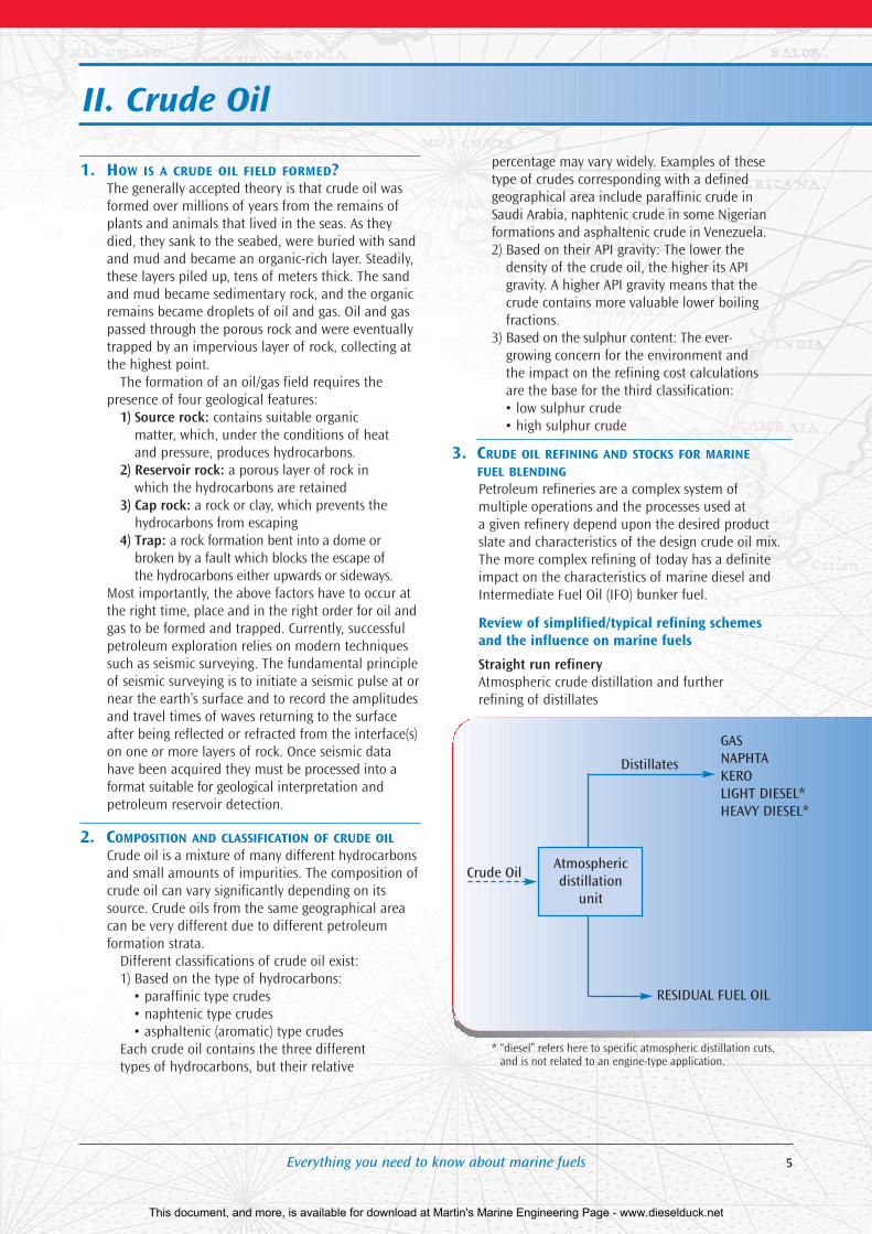
3. CRUDE OIL REFINING AND STOCKS FOR MARINEFUEL BLENDINGPetroleum refineries are a complex system ofmultiple operations and the processes used at a given refinery depend upon the desired productslate and characteristics of the design crude oil mix.The more complex refining of today has a definiteimpact on the characteristics of marine diesel andIntermediate Fuel Oil (IFO) bunker fuel.
Review of simplified/typical refining schemes and the influence on marine fuels
Straight run refineryAtmospheric crude distillation and further refining of distillates
* “diesel” refers here to specific atmospheric distillation cuts,and is not related to an engine-type application.
GASNAPHTAKEROLIGHT DIESEL*HEAVY DIESEL*
Distillates
Atmospheric distillation
unit
RESIDUAL FUEL OIL
Crude Oil
II. Crude Oil
This document, and more, is available for download at Martin's Marine Engineering Page - www.dieselduck.net
Straight run stocks for marine fuel blendingLight diesel, heavy diesel, and straight run residue.
Straight run marine gasoil and distillate marine diesel
Marine gasoil and distillate type MDO are manu-factured from kero, light, and heavy gasoil fractions.For DMC type gasoil, up to 10–15% residual fuel can be added.
Straight run IFO 380 mm2/s (at 50°C)This grade is made starting from the atmosphericresidue fraction (typical viscosity of about 800 mm2/sat 50°C) by blending with a gasoil fraction.
Straight run lower viscosity grade IFOsBlending to lower grade IFOs is done from the IFO380 mm2/s (at 50°C) using a gasoil type cutterstock or with marine diesel.
All IFOs have good ignition characteristics, due to thehigh percentage of paraffinic material still present inthe atmospheric residue, and the paraffinic nature ofthe cutterstocks used. The high amount of paraffinichydrocarbons in the straight run type marine fuelsleads to relatively low densities for these products,ensuring easy and efficient onboard fuel purification.
The product slate of a straight run type refinery, withits heavy fuel production of approximately 50% ofthe crude feed, does not correspond to the productdemand in the industrialized countries where a highdemand for light products (jet fuel, gasoline, andgasoil) goes together with a strong reduction in thedemand for heavy fuel (10 to 15% of the crude oil).This results in the need to convert the residue fraction into light fractions, (also more valuable) and to the construction of complex refineries.
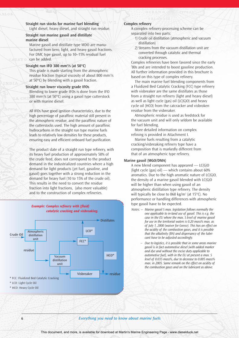
Complex refineryA complex refinery-processing scheme can be separated into two parts:
1) Crude oil distillation (atmospheric and vacuumdistillation)
2) Streams from the vacuum distillation unit areconverted through catalytic and thermalcracking processes.
Complex refineries have been favored since the early’80s and are intended to boost gasoline production.All further information provided in this brochure isbased on this type of complex refinery.
The main marine fuel blending components froma Fluidized Bed Catalytic Cracking (FCC) type refinerywith visbreaker are the same distillates as those from a straight run refinery (light and heavy diesel) as well as light cycle (gas) oil (LC(G)O) and heavy cycle oil (HCO) from the catcracker and visbrokenresidue from the visbreaker.
Atmospheric residue is used as feedstock for the vacuum unit and will only seldom be availablefor fuel blending.
More detailed information on complex refining is provided in Attachment I.
Marine fuels resulting from a catalytic cracking/visbreaking refinery type have a composition that is markedly different from that of an atmospheric type refinery.
Marine gasoil (MGO/DMA)A new blend component has appeared — LC(G)O(light cycle (gas) oil) — which contains about 60%aromatics. Due to the high aromatic nature of LC(G)O,the density of a marine gasoil blended with LC(G)Owill be higher than when using gasoil of an atmospheric distillation type refinery. The density will typically be close to 860 kg/m3 (at 15°C). No performance or handling differences with atmospherictype gasoil have to be expected.Notes: – Marine gasoil S max. legislation follows normally the
one applicable to in-land use of gasoil. This is e.g. thecase in the EU where the max. S level of marine gasoilfor use in the territorial waters is 0.20 mass% max. asof July 1, 2000 (waiver for Greece). This has an effect onthe acidity of the combustion gases, and it is possiblethat the alkalinity (BN) and dispersancy of the lubri-cant have to be adjusted accordingly.
– Due to logistics, it is possible that in some areas marinegasoil is in fact automotive diesel (with added markerand dye and without the excise duty applicable toautomotive fuel), with in the EU at present a max. Slevel of 0.035 mass%, due to decrease to 0.005 mass%max. in 2005. Same remark on the effect on acidity ofthe combustion gases and on the lubricant as above.
6 Everything you need to know about marine fuels
Example: Complex refinery with (fluid) catalytic cracking and visbreaking.
Distillates
residue
Atmospheric distillation
unit
Vacuum distillation
unit
FCC*
LCO*
HCO*
Visbreaker
residue
Crude Oil
* FCC: Fluidized Bed Catalytic Cracking
* LCO: Light Cycle Oil
* HCO: Heavy Cycle Oil
This document, and more, is available for download at Martin's Marine Engineering Page - www.dieselduck.net

Distillate marine diesel (MDO/DMB)Distillate marine diesel (commercial denomination)typically has a lower cetane number than marinegasoil, and a higher density. With the productionslate of a catalytic cracking refinery, distillate marinediesel can therefore contain a higher percentage ofLC(G)O than marine gasoil.
Note: Worldwide, marine diesel has a sulphur content betweenapprox. 0.3 and 2.0 mass%. Due to recent EU legislation, thislevel is for the territorial waters belonging to the EU the samelevel as for gasoil, i.e. 0.20 mass% max. as of July 1, 2000(waiver for Greece). This will have an effect on the acidity ofthe combustion gases, and it has to be taken into account forthe lubrication of vessels using marine diesel, mainly whenoperating most of the time between EU ports.
Blended marine diesel (MDO/DMC)With atmospheric type refining, blended marinediesel (MDO/DMC) can contain up to 10% IFO witheither marine gasoil (MGO/DMA) or distillate marinediesel (MD)/DMB). With complex refining, blendedmarine diesel (MDO/DMC) no longer corresponds to aspecific composition and extreme care must be usedwhen blending this grade to prevent stability and/orcombustion problems.
IFO-380This grade is usually manufactured at the refineryand contains visbroken residue, HCO and LC(G)O.These three components influence the characteristicsof the visbroken IF-380.
Vacuum distillation reduces the residue yield toabout 20% of the crude feed, unavoidably leading to a concentration of the heaviest molecules in this fraction. Visbreaking converts about 25% of its vacuumresidue feed into distillate fractions. This means thatabout 15% of the original crude remains as visbrokenresidue. The asphaltene1, sulphur and metal content in
visbroken residue are 3 to 3.5 times higher than inatmospheric residue. Visbreaking affects the molecularstructure: molecules are broken thermally and thiscan deteriorate the stability of the asphaltenes.
HCO (typical viscosity at 50°C: 130 mm2/s) containsapproximately 60% aromatics, and is a high-densityfraction: the density at 15°C is above 1 kg/l (typically1.02). It is the bottom fraction of the FCC unit. Thecatalytic process of this unit is based on an aluminumsilicate. Some mechanical deterioration of the catalystoccurs in the FCC process, and the resulting cat finesare removed from the HCO in the refinery. Thisremoval however, is not 100% efficient, and a certainamount (ppm level) of cat fines remains in the HCO, and from there end up in heavy fuel blendedwith HCO (further discussed in Chapter III-2 on thesignificance of the marine fuel specifications).
The aromaticity of HCO assists in ensuring optimumstability for the visbroken fuel blend.
LC(G)O (typical viscosity at 50°C: 2.5 mm2/s) has thesame aromaticity as HCO, but is a distillate fraction ofthe FCC unit, with a distillation range comparable tothat of gasoil. With a typical density of 0.94 kg/l at15°C, it is used to fine-tune the marine heavy fuel oilblending where generally a density maximum limitof 0.9910 kg/l has to be observed.
IFOs < 380 mm2/sThese grades are generally blended starting from 380mm2/s IFOs (at 50°C), by using a suitable cutterstock(marine diesel, gasoil, LC(G)O, or a mixture of these).The blend composition has to be construed in such away that the product stability is safeguarded, while atthe same time direct or indirect density limits are fulfilled (further discussed in Chapter III-2 on the significance of the marine fuel specifications).
7Everything you need to know about marine fuels
1 asphaltenes: residual fuel components which are insoluble in heptane but soluble in toluene.
This document, and more, is available for download at Martin's Marine Engineering Page - www.dieselduck.net

8 Everything you need to know about marine fuels
This document, and more, is available for download at Martin's Marine Engineering Page - www.dieselduck.net
9Everything you need to know about marine fuels
1. FUEL OIL APPLICATIONSFuel oil applications are all based on energy becomingavailable through the burning of fuel oil. Fuel oil combustion (oxidation reaction) releases a largeamount of heat, which can be used for steam generation, e.g. for steam turbines. The high volume (pressure) of the combustion gases can be useddirectly to drive an engine, or (less frequent for HFO,but widespread for gasoil) a gas turbine.
When fuel oil is burned, an amount of heat isreleased, which is defined by the specific energy(international unit MJ/kg) of the fuel.
Thermal plants use this heat to generate steam,which then drives steam turbines, thus providingmechanical energy that can be used for propulsion or be converted into electrical energy.
For marine engines and gas turbines, mechanicalenergy provided by the combustion gases is usedeither directly for propulsion, or converted into elec-trical energy for power plants. For larger installations,cost efficiency optimization and environmental constraints are leading to the introduction of co-generation. In co-generation, part of the energy lost in the generation of electrical energy is madeavailable under the form of low-pressure steam, suitable for a wide range of heating applications.
2. FUEL SPECIFICATIONSThe different types of fuel oil applications and environmental considerations have led to differenttypes of fuel oil specifications. These are much moredemanding than the original fuel oil n° 6 or Bunker C requirements when all heavy fuel was used for thermal plants and steam turbines. Emission standards for thermal plants can vary widely, depending on the geographical area. Since all emitted SO2 originates from sulphur in the fuel, emission standards on SO2 automatically limit thesulphur content of the fuel, except for large combustion plants, where the standard can be economically met by flue gas desulphurization.
In the late 1960s marine diesel engines were theprimary means of ship propulsion. Initially, andthrough the late 1970s, the different marine engineheavy fuel oil grades remained identified solely bytheir maximum viscosity. This worked well with heavyfuel originating from atmospheric refineries. Fuelrelated operational problems arose with the generalizedupgrading of refinery operations in the second half ofthe 1970s from straight run to complex refining.
1982 saw the publication of marine fuel specificationrequirements by the British Standard Organization (BS MA 100), and by CIMAC (Conseil International de Machines à Combustion).
III. Fuel Oil
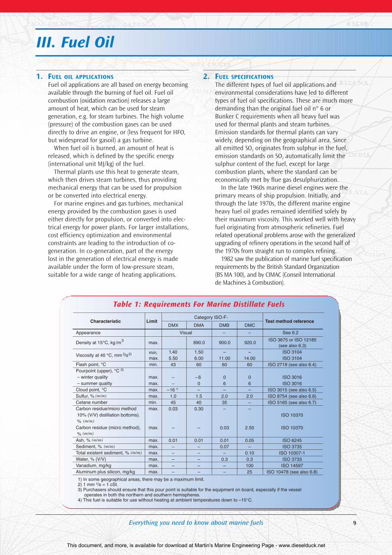
Table 1: Requirements For Marine Distillate Fuels
This document, and more, is available for download at Martin's Marine Engineering Page - www.dieselduck.net
10 Everything you need to know about marine fuels
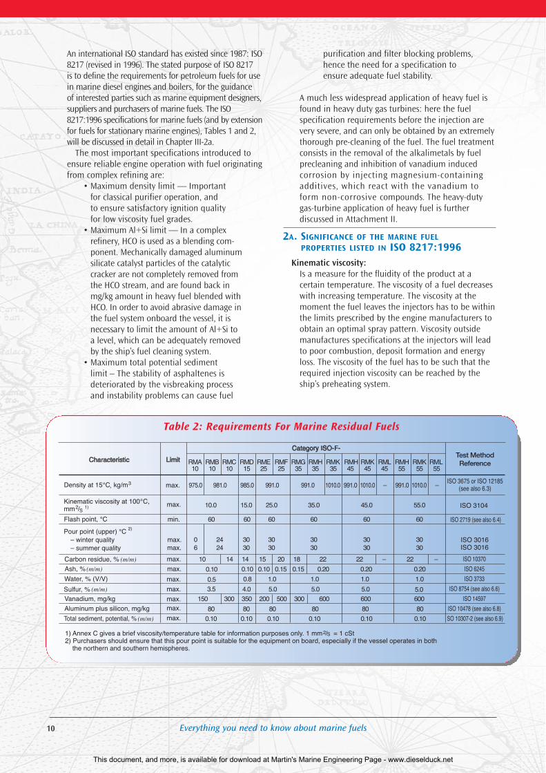
An international ISO standard has existed since 1987: ISO8217 (revised in 1996). The stated purpose of ISO 8217 is to define the requirements for petroleum fuels for usein marine diesel engines and boilers, for the guidance of interested parties such as marine equipment designers,suppliers and purchasers of marine fuels. The ISO8217:1996 specifications for marine fuels (and by extensionfor fuels for stationary marine engines), Tables 1 and 2,will be discussed in detail in Chapter III-2a.
The most important specifications introduced toensure reliable engine operation with fuel originatingfrom complex refining are:
• Maximum density limit — Important for classical purifier operation, and to ensure satisfactory ignition quality for low viscosity fuel grades.
• Maximum Al+Si limit — In a complexrefinery, HCO is used as a blending com-ponent. Mechanically damaged aluminumsilicate catalyst particles of the catalyticcracker are not completely removed fromthe HCO stream, and are found back inmg/kg amount in heavy fuel blended withHCO. In order to avoid abrasive damage inthe fuel system onboard the vessel, it isnecessary to limit the amount of Al+Si toa level, which can be adequately removedby the ship’s fuel cleaning system.
• Maximum total potential sediment limit – The stability of asphaltenes isdeteriorated by the visbreaking processand instability problems can cause fuel
purification and filter blocking problems,hence the need for a specification toensure adequate fuel stability.
A much less widespread application of heavy fuel isfound in heavy duty gas turbines: here the fuel specification requirements before the injection arevery severe, and can only be obtained by an extremelythorough pre-cleaning of the fuel. The fuel treatmentconsists in the removal of the alkalimetals by fuelprecleaning and inhibition of vanadium induced corrosion by injecting magnesium-containingadditives, which react with the vanadium toform non-corrosive compounds. The heavy-dutygas-turbine application of heavy fuel is further discussed in Attachment II.
2A. SIGNIFICANCE OF THE MARINE FUELPROPERTIES LISTED IN ISO 8217:1996
Kinematic viscosity:Is a measure for the fluidity of the product at a certain temperature. The viscosity of a fuel decreaseswith increasing temperature. The viscosity at themoment the fuel leaves the injectors has to be withinthe limits prescribed by the engine manufacturers toobtain an optimal spray pattern. Viscosity outsidemanufactures specifications at the injectors will leadto poor combustion, deposit formation and energyloss. The viscosity of the fuel has to be such that therequired injection viscosity can be reached by theship’s preheating system.
Table 2: Requirements For Marine Residual Fuels
This document, and more, is available for download at Martin's Marine Engineering Page - www.dieselduck.net
11Everything you need to know about marine fuels
Density:The official unit is kg/m3 at 15°C, while kg/l at 15°C is the most commonly used unit. Density is used inthe calculation of the quantity of fuel delivered.From a technical point of view, the density gives anindication of the ignition quality of the fuel within a certain product class, this is particularly the case for the low viscosity IFOs. The product density isimportant for the onboard purification of the fuel;the higher the density the more critical it becomes(see Chapter III-4 on fuel oil treatment).
Cetane number, cetane index:Only applicable for gasoil and distillate fuels. It is ameasure for the ignition quality of the fuel in a dieselengine. The higher the rpm of the engine, the higherthe required cetane number. The cetane number isdetermined on an engine. The cetane index — anapproximate value of the cetane number based on thedensity and the distillation of the fuel — can be calcu-lated and is usually used. The cetane index is not appli-cable when cetane-improving additives have been used.
Carbon residue:A carbon residue determination is a typical laboratorytest performed under specified reduced air supply anddoes not represent combustion conditions in an engine.It gives an indication of the amount of hydrocarbons inthe fuel which have difficult combustion characteristics,but there is no conclusive correlation between carbonresidue figures and actual field experience. The microcarbon residue method is specified by ISO 8217.
Ash:The ash content is a measure of the metals presentin the fuel, either as inherent to the fuel, or as contamination.
Flash point:Flash point is the temperature at which the vapors ofa fuel ignite (under specified test conditions), when atest flame is applied. The flash point for all fuels tobe used in bulk onboard vessels is set at PM, CC, 60°Cminimum (SOLAS agreement). DMX, a special lowcloud point gasoil, may only be stored onboard indrums because of its <60°C flash point.
Sulphur:The sulphur content of a marine fuel depends on thecrude oil origin and the refining process. When a fuelburns, sulphur is converted into sulphur oxides. Theseoxides reach the lubricating oil via the blow-by gas.These oxides are corrosive to engine piston liningsand must be neutralized by the cylinder lubricant.Marine engine lubricants are developed to cope withthis acidity (high BN). If the correct lubricant is used,the sulphur content of a marine fuel is technically not important (although it has environmental implications in sensitive areas such as the Baltic Sea).
Water content:Water in fuel is a contamination and does not yieldany energy. The percentage of water in the fuel can
be translated into a corresponding energy loss for thecustomer. Water is removed onboard the vessel bycentrifugal purification. If after purification the watercontent remains too high, water vapor lock can occurand pumps can cut out. If water-contaminated fuelreaches the injectors, combustion can be erratic.Water in fuel which remains standing in lines for alonger period can cause corrosion.
Pour point: Pour point is the lowest temperature at which a fuelwill continue to flow when it is cooled under specifiedstandard conditions. Contrary to straight run type heavyfuels (pour point typically in the +20°C range), bunkerfuels from a complex refinery generally have pour pointsbelow 0°C (range –10 to –20°C). This is reflected in thefact that bunker fuel tanks are generally not completelyheated any more, but only before the fuel transferpump. This can then lead to problems, if a vesselreceives high pour straight run bunker fuel. For distil-late marine diesel, the cold temperature behavior iscontrolled in ISO 8217 by a pour point maximum.With marine diesels with a high content of heavier n-paraffins vigilance is required if strongtemperature changes are expected (wax settling canoccur, even when the pour point specification is met).
Elements:Vanadium and nickel are elements found in certainheavy fuel oil molecules (asphaltenes). Upon combustionvanadiumoxides are formed and some of them havecritical melting temperatures. The most critical are thedouble oxides/sulphates with sodium. Some countrieshave implemented maximum Ni concentrations forinland use of heavy fuel (emission regulations).
Total sediment, potential:Inorganic material naturally occurring in crude oil isremoved in the refineries prior to the atmospheric dis-tillation. Some minor contamination (e.g. ironoxides) ofa finished heavy fuel can not be excluded. The biggestrisk for sediment formation in heavy fuel is due topotential coagulation of organic material inherent tothe fuel itself: visbroken asphaltenes, if insufficientlystable, can form sediment (coagulation is influencedby time and temperature). A decrease in aromaticity ofthe fuel matrix by blending with paraffinic cutterstockscan also deteriorate the stability of the asphaltenes. Incases of heavy fuel instability, it is only a relative smallfraction of the asphaltenes which forms sediment, butthis organic sediment includes in its mass some of thefuel itself, and water (onboard purifying problems),and the amount of generated sludge can becomequite high. The total potential sediment gives the totalamount of sediment that can be formed under normalstorage conditions, excluding external influences. Ifthe total potential sediment of the heavy fuel oilmarkedly exceeds the specification value (0.10 % (m/m)max for all grades of IFOs and HFOs), problems withthe fuel cleaning system can occur, fuel filters can getplugged and combustion become erratic.
This document, and more, is available for download at Martin's Marine Engineering Page - www.dieselduck.net
12 Everything you need to know about marine fuels
Catalytic fines:As described previously, HCO is used worldwide in complex refining as a blending component for heavyfuel. Mechanically damaged catalyst particles (alu-minum silicate) cannot be removed completely in acost-effective way, and are found in blended heavy fuel.Fuel precleaning onboard ships has a removal efficiencyof approximately 80% for catalyst fines. In order toavoid abrasive wear of fuel pumps and injectors, amaximum limit of 80 mg/kg for Al+Si has been definedin ISO 8217.
Calculated carbon aromaticity index, CCAI: CCAI is an indicator of the ignition delay of an IFO. CCAI is calculated from the density and the viscosity of the fuel oil. Although it is not an officialspecification, it has found its way in many users’bunker fuel specification requirements. Some manufacturers specify CCAI limits for their engines,depending on engine type and application.
2B.CORRESPONDENCE OF SPECIFICATIONSAND TEST METHODSISO 8217:1996 lists the test requirements and methodsfor the testing. While in theory these methods should be used worldwide for testing marine fuels,experience has shown that this is not always the case.In some areas other test methods, in some cases precursors of the presently defined ISO methods, arestill being used. The correspondence (discrepancy)between such test methods/results and the test methods/data of ISO 8217 are described hereafter.
Density:The mass (weight in vacuum) of the liquid per unitvolume at 15°C. Official unit: kg/m3. Often used variant: kg/l. The density limits in ISO 8217 areexpressed in kg/m3. Specific gravity 60/60°F: Specificgravity is the ratio of the mass of a given volume ofliquid at 60°F to the mass of an equal volume ofpure water at the same temperature. No unit.
API gravity:Is a function of the specific gravity 60/60°F. API gravity is expressed as degrees API.
API gravity, deg = (141.5 / spec. gr. 60/60°F) –131.5
Micro Carbon Residue (MCR):MCR is the carbon residue test prescribed by ISO8217:1996. The formerly used carbon residue testwas Conradson Carbon Residue. The test resultobtained with MCR is the same as with CCR, but MCR is a relatively quick test method and has a better precision than CCR.
Al+Si:The ISO 8217 prescribed test method is ISO 10478,and only this method and fully equivalent methodsfrom National Standardization Organizations should be used. A former industry wide limit for catalyst fines in heavy fuel was defined on Al alone(30 mg/kg max.). The ratio between Al and Si canhowever vary considerably between different typesand manufacturers of aluminum silicate catalyst. Thisis the reason for the test requirement change to thesum of Al and Si. In practice, the two ways of limitingthe catalytic fines content in heavy fuel give the samedegree of protection.
Sediment and Total Potential Sediment:Differentiation has to be made between tests forinorganic sediment and organic sediment, existentsediment and potential sediment.
According to ISO 8217: 1996 inorganic sediment(rust, sand) determination (ISO 3735) is only applicableto DMB type marine diesel. The method (and equivalent methods) will not determine sedimentfrom organic origin, due to the aromatic nature(toluene) of the extraction solvent.
Organic type sediment can occur in DMC typemarine diesel and in intermediate fuel oils. Thecause of the formation of organic type sedimentresides in the thermal cracking of the heaviest molecules of crude, generally in visbreaking operations. Asphaltenes, the heaviest molecules ofcrude, can become unstable by thermal cracking, andmust be carefully monitored by the refineries. Oncevisbroken, the asphaltenes are more or less sensitiveto changes in the aromaticity of the total fuel matrix.This has to be taken into account for fuel blendingwhen using visbroken type heavy fuel and gasoil type(paraffinic) blending stocks. The asphaltene sedimentformation is a function of time and temperature(excluding external influences), and an unstable fuelwill only reach its final sediment formation after acertain storage time. The sediment present in a sample of heavy fuel at a certain moment is given by the total existent sediment test, but there is nocertainty that this figure corresponds to the condition of the bulk of the fuel at that same time.The total potential sediment test gives the totalamount of sediment that can be formed under normal storage conditions, excluding external influences. The prescribed test method is ISO 10307-2(IP 390+375 is equivalent).
The test method originally used in the industry for determination of total sediment is the Shell HotFiltration Test; the test results can be existing sedimentor potential sediment, depending on the ageingprocedure. The results of this test are not equivalentto those of ISO 10307-2, due to a difference in thesolvent used for the test. The Shell Hot Filtration testwith ageing generally gives slightly higher results.
This document, and more, is available for download at Martin's Marine Engineering Page - www.dieselduck.net
Everything you need to know about marine fuels
Viscosity:Kinematic viscosity is the only accepted method,expressed in mm2/s at a certain temperature, forbunker fuel deliveries usually 50°C. ISO 8217:1996lists the maximum kinematic viscosities at 100°C(note: 1 mm2/s = 1cSt). SSU, SSF and RW1 (SayboltSeconds Universal, Saybolt Seconds Furol andRedwood No. 1) are obsolete units.
3. TEST SPECIFICATIONS AND PRECISIONISO 8217:1996 not only specifies the Requirementsfor Marine Distillate and Residual fuels and the testmethod references, it also lists the method applicablefor the use of precision data in relation to the methods of the test: ISO 4259:1992, “Petroleum products — determination and application of preci-sion data in relation to methods of test”.
The application of precision data in relation tomethods of test automatically assumes that the sample taking has been performed to the best industry standard possible, and that the sample isrepresentative for the supply. Experience shows thatthe sample itself is often the weakest point in thechain. In cases of complaints and claims, FAMM onlyrecognizes the bunker fuel retain samples taken byits representative (e.g. bunker barge attendant) at themoment of the bunkering as valid. The full detailsare described in the FAMM Terms of Sale.
Should a dispute arise due to a difference betweentest data obtained on valid retain samples by two different laboratories (one acting on behalf of thesupplier, the other on behalf of the customer), ISO4259 should be used to evaluate the validity of theresults. If the reproducibility of the test method ismet, both values are considered acceptable, and theaverage of the two is taken as the true value. If thereproducibility is not met, both results have to berejected, and the guidelines set forth in ISO 4259should be followed to solve the problem. This canhowever be very time-consuming, and is very seldomdone in practice. Both parties generally agree to theuse of a third laboratory, of which the result will thenbe binding for both parties.
It has to be noted that reproducibility limits areonly applicable between two analysis figures on thesame sample (or samples considered as being thesame). The reproducibility of a test method may not be invoked to explain a deviation versus a specification limit.
The testing margin, however, has an effect on asingle result, e.g. the analysis result on a certain specification test obtained by the end user. If the enduser has no other information on the true value ofthe characteristic than his own (single) test result, it isaccepted with 95% confidence that the product failsthe specification limit when the result exceeds thespec limit by more than 0.59R (where R is the repro-ducibility of the test method) in case of an upper limit,and is more than 0.59R lower than the specificationlimit, in the case of a lower limit.
Although given less credit in real life situationsthan it really deserves, the significance of the reproducibility may not be underestimated. It is thebasis for all quality control against specifications.Without reproducibility data, test results would loosea major part of their significance, since there would be no way to define how close a test resultapproaches the true value.
Attachment II lists the methods for marine fueltesting listed in ISO 8217:1996, together with theirreproducibility. Whenever national standardizationmethods of testing are used, the full correspondencewith the ISO prescribed method has to be checked.There can also be some differences in the precision data.
4. ONBOARD FUEL OIL TREATMENTIn the late ’70s, the increasing market demand fordistillate type fuels (gasoline, diesel) and the resultingchanges in refinery processes to cope with thisdemand have resulted in a deterioration of the heavyfuel quality. Efficient cleaning of heavy fuel oil ismandatory to achieve reliable and economical operation of diesel engines burning heavy fuel.
Examples:• Water is a common contaminant in fuel
oil. Apart from water content in the fuel oil due to transport, there can be a further contamination in the storage tank due to water condensation as a result oftemperature changes.
• Catalyst fines from aluminum silicate catalystused in the catalytic cracking process mayend up in the heavy fuel and have to beremoved to avoid abrasive wear of variousengine parts.
Fuel from the storage tank is pumped to the settlingtank and contaminants (water, solids) sink to the bottom of the tank under influence of the gravityforce (g). The rate of separation by gravity, Vg isdefined by Stokes’ law:
Vg = [d2 (ρ2 - ρ1) / 18 η] gd : particle diameterρ2: particle densityρ1: density of the fuel oilη : viscosity of the fuel oilg : gravitational acceleration.
Complete separation in a reasonable period of timecan only be achieved by mechanically generated centrifugal force. Fuel from the settling tank is fed toa centrifugal system or purifier and water and solidsare separated out of the fuel. The rate of separationin a centrifugal field (V) is defined as:
V= Vg x Zwhere Z equals rω2/g (r = distance of the particlefrom the axis of rotation, ω is the angular velocity).The factor Z specifies how much greater the sedimentation rate is in the centrifugal field compared to the gravitational field.
13
This document, and more, is available for download at Martin's Marine Engineering Page - www.dieselduck.net
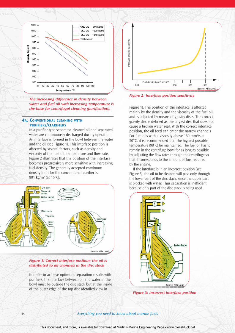
The increasing difference in density betweenwater and fuel oil with increasing temperature isthe base for centrifugal cleaning (purification).
4A. CONVENTIONAL CLEANING WITHPURIFIERS/CLARIFIERSIn a purifier type separator, cleaned oil and separatedwater are continuously discharged during operation.An interface is formed in the bowl between the waterand the oil (see Figure 1). This interface position isaffected by several factors, such as density and viscosity of the fuel oil, temperature and flow rate.Figure 2 illustrates that the position of the interfacebecomes progressively more sensitive with increasingfuel density. The generally accepted maximum density limit for the conventional purifier is 991 kg/m3 (at 15°C).
Figure 1: Correct interface position: the oil is distributed to all channels in the disc stack
In order to achieve optimum separation results withpurifiers, the interface between oil and water in thebowl must be outside the disc stack but at the insideof the outer edge of the top disc (detailed view in
Figure 2: Interface position sensitivity
Figure 1). The position of the interface is affectedmainly by the density and the viscosity of the fuel oil.and is adjusted by means of gravity discs. The correctgravity disc is defined as the largest disc that does notcause a broken water seal. With the correct interfaceposition, the oil feed can enter the narrow channelsFor fuel oils with a viscosity above 180 mm2/s at50°C, it is recommended that the highest possibletemperature (98°C) be maintained. The fuel oil has toremain in the centrifuge bowl for as long as possible by adjusting the flow rates through the centrifuge sothat it corresponds to the amount of fuel required by the engine.
If the interface is in an incorrect position (see Figure 3), the oil to be cleaned will pass only throughthe lower part of the disc stack, since the upper part is blocked with water. Thus separation is inefficientbecause only part of the disc stack is being used.
Figure 3: Incorrect interface position
14 Everything you need to know about marine fuels
840 950 970 991Fuel density kg/m3 at 15°C
Inte
rfac
e po
sitio
n se
nsiti
vity
(Source: Alfa Laval)
(Source: Alfa Laval)
(Source: Alfa Laval)
This document, and more, is available for download at Martin's Marine Engineering Page - www.dieselduck.net
15Everything you need to know about marine fuels
To ensure optimal cleaning of a fuel oil, a secondseparator can be used in series operation, e.g. a purifier followed by a clarifier. The density limit of991 kg/m3 is not applicable to clarifier operation, butthe combined system of purifier and clarifier in seriesremains restricted to a maximum density of 991kg/m3 at 15°C. Heavy movements of the vessel canstir up dirt, water and sludge that have accumulatedover time on the bottom of the bunker and settlingtanks. It is therefore potentially possible that efficientpurification is not always obtained when separatorshave been put in a parallel purifying function.
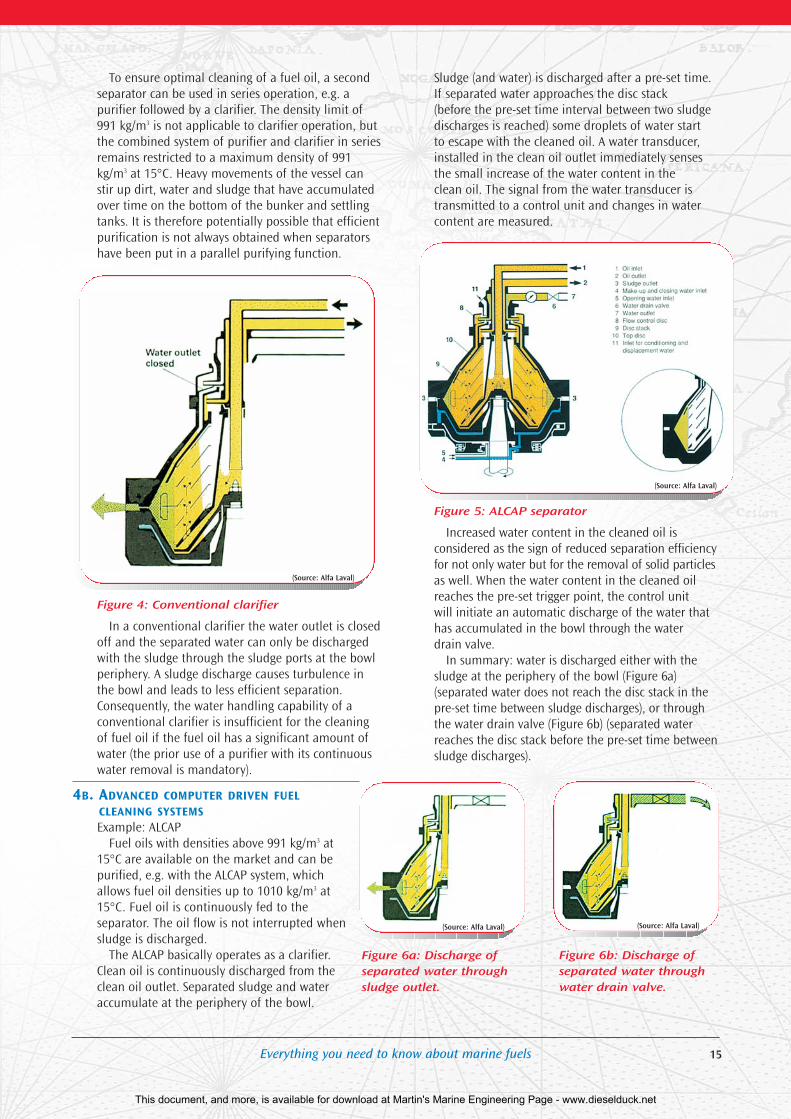
Figure 4: Conventional clarifier
In a conventional clarifier the water outlet is closedoff and the separated water can only be dischargedwith the sludge through the sludge ports at the bowlperiphery. A sludge discharge causes turbulence inthe bowl and leads to less efficient separation.Consequently, the water handling capability of a conventional clarifier is insufficient for the cleaningof fuel oil if the fuel oil has a significant amount ofwater (the prior use of a purifier with its continuouswater removal is mandatory).
4B. ADVANCED COMPUTER DRIVEN FUELCLEANING SYSTEMSExample: ALCAP
Fuel oils with densities above 991 kg/m3 at15°C are available on the market and can bepurified, e.g. with the ALCAP system, whichallows fuel oil densities up to 1010 kg/m3 at15°C. Fuel oil is continuously fed to the separator. The oil flow is not interrupted whensludge is discharged.
The ALCAP basically operates as a clarifier.Clean oil is continuously discharged from theclean oil outlet. Separated sludge and wateraccumulate at the periphery of the bowl.
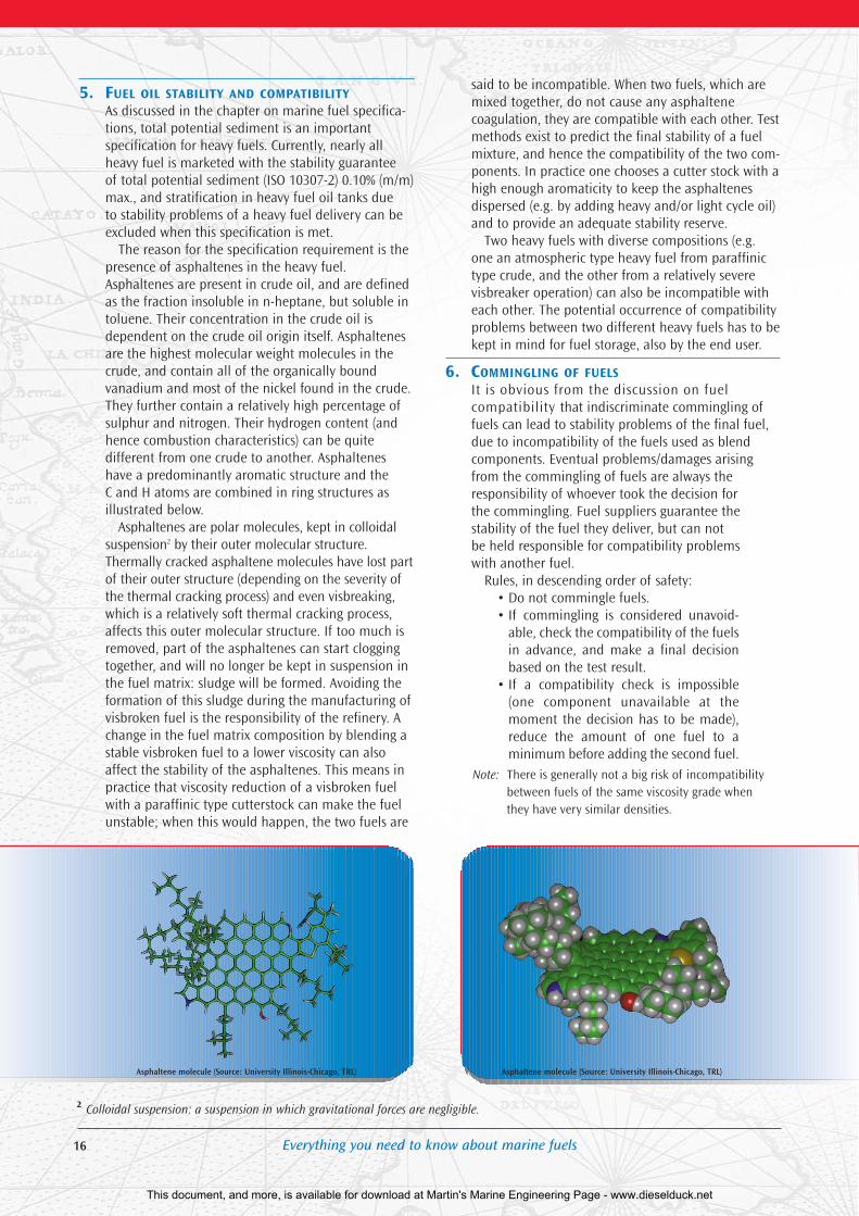
Sludge (and water) is discharged after a pre-set time.If separated water approaches the disc stack (before the pre-set time interval between two sludgedischarges is reached) some droplets of water start to escape with the cleaned oil. A water transducer,installed in the clean oil outlet immediately sensesthe small increase of the water content in the clean oil. The signal from the water transducer istransmitted to a control unit and changes in watercontent are measured.
Figure 5: ALCAP separator
Increased water content in the cleaned oil is considered as the sign of reduced separation efficiencyfor not only water but for the removal of solid particlesas well. When the water content in the cleaned oilreaches the pre-set trigger point, the control unit will initiate an automatic discharge of the water thathas accumulated in the bowl through the water drain valve.
In summary: water is discharged either with thesludge at the periphery of the bowl (Figure 6a) (separated water does not reach the disc stack in thepre-set time between sludge discharges), or throughthe water drain valve (Figure 6b) (separated waterreaches the disc stack before the pre-set time betweensludge discharges).
Figure 6a: Discharge ofseparated water throughsludge outlet.
Figure 6b: Discharge ofseparated water throughwater drain valve.
(Source: Alfa Laval)
(Source: Alfa Laval)
(Source: Alfa Laval) (Source: Alfa Laval)
This document, and more, is available for download at Martin's Marine Engineering Page - www.dieselduck.net
16 Everything you need to know about marine fuels
5. FUEL OIL STABILITY AND COMPATIBILITYAs discussed in the chapter on marine fuel specifica-tions, total potential sediment is an important specification for heavy fuels. Currently, nearly allheavy fuel is marketed with the stability guarantee of total potential sediment (ISO 10307-2) 0.10% (m/m)max., and stratification in heavy fuel oil tanks due to stability problems of a heavy fuel delivery can beexcluded when this specification is met.
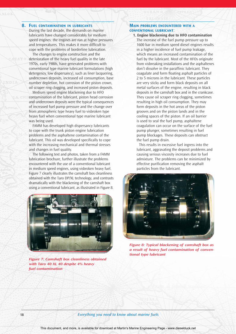
The reason for the specification requirement is thepresence of asphaltenes in the heavy fuel.Asphaltenes are present in crude oil, and are definedas the fraction insoluble in n-heptane, but soluble intoluene. Their concentration in the crude oil isdependent on the crude oil origin itself. Asphaltenesare the highest molecular weight molecules in thecrude, and contain all of the organically bound vanadium and most of the nickel found in the crude.They further contain a relatively high percentage ofsulphur and nitrogen. Their hydrogen content (andhence combustion characteristics) can be quite different from one crude to another. Asphalteneshave a predominantly aromatic structure and the C and H atoms are combined in ring structures as illustrated below.
Asphaltenes are polar molecules, kept in colloidalsuspension2 by their outer molecular structure.Thermally cracked asphaltene molecules have lost partof their outer structure (depending on the severity ofthe thermal cracking process) and even visbreaking,which is a relatively soft thermal cracking process,affects this outer molecular structure. If too much isremoved, part of the asphaltenes can start cloggingtogether, and will no longer be kept in suspension inthe fuel matrix: sludge will be formed. Avoiding theformation of this sludge during the manufacturing ofvisbroken fuel is the responsibility of the refinery. Achange in the fuel matrix composition by blending astable visbroken fuel to a lower viscosity can alsoaffect the stability of the asphaltenes. This means inpractice that viscosity reduction of a visbroken fuelwith a paraffinic type cutterstock can make the fuel unstable; when this would happen, the two fuels are
said to be incompatible. When two fuels, which aremixed together, do not cause any asphaltene coagulation, they are compatible with each other. Testmethods exist to predict the final stability of a fuelmixture, and hence the compatibility of the two com-ponents. In practice one chooses a cutter stock with ahigh enough aromaticity to keep the asphaltenes dispersed (e.g. by adding heavy and/or light cycle oil)and to provide an adequate stability reserve.
Two heavy fuels with diverse compositions (e.g.one an atmospheric type heavy fuel from paraffinictype crude, and the other from a relatively severe visbreaker operation) can also be incompatible witheach other. The potential occurrence of compatibilityproblems between two different heavy fuels has to bekept in mind for fuel storage, also by the end user.
6. COMMINGLING OF FUELSIt is obvious from the discussion on fuel compatibility that indiscriminate commingling offuels can lead to stability problems of the final fuel,due to incompatibility of the fuels used as blend components. Eventual problems/damages arisingfrom the commingling of fuels are always the responsibility of whoever took the decision for the commingling. Fuel suppliers guarantee the stability of the fuel they deliver, but can not be held responsible for compatibility problems with another fuel.
Rules, in descending order of safety:• Do not commingle fuels.• If commingling is considered unavoid-
able, check the compatibility of the fuelsin advance, and make a final decisionbased on the test result.
• If a compatibility check is impossible(one component unavailable at themoment the decision has to be made),reduce the amount of one fuel to a minimum before adding the second fuel.
Note: There is generally not a big risk of incompatibilitybetween fuels of the same viscosity grade when they have very similar densities.
2 Colloidal suspension: a suspension in which gravitational forces are negligible.
Asphaltene molecule (Source: University Illinois-Chicago, TRL) Asphaltene molecule (Source: University Illinois-Chicago, TRL)
This document, and more, is available for download at Martin's Marine Engineering Page - www.dieselduck.net

Everything you need to know about marine fuels
7. MICROBIOLOGICAL CONTAMINATIONPlugging of filters on gasoil and marine distillate fuelfeed lines can be caused by microbiological contamination (bacteria, fungi and yeast).
Microbiological contamination can always occur,especially if the temperature conditions are favorable(between 15 and 40°C, for the most common types),and if non-dissolved water is present in the fuel.
NO WATER = NO MICROBIOLOGICALCONTAMINATION.
The ideal conditions for the development ofmicrobiological contamination occur in tropical andsub-tropical regions: high air humidity combinedwith a high ambient temperature.
A first screening for the possible site of the contamination can be made from the number ofcomplaints: several simultaneous complaints makethe supply chain suspect, a single complaint makes a contamination at the site of the customer more plausible.
Following is a summary of the topics quoted byVOS, the Dutch organization that supervises the quality aspects of gasoil delivered in the Netherlandsto fishing and inland waterway vessels:
• Good water-housekeeping is essential.• No water: no bacterial contamination.• Fuel producing companies, dealers, and
end-users have a common responsibility:bacterial contamination can occur ineach link of the chain.
• Consequences of bacterial contamination:filthy fuel system, plugged fuel filters and erratic engine operation.
• How can it be recognized: slime,sludge, possibly corrosion in filters,tanks, lines.
• What can the end-user do:– Make sure no water enters the gasoil– Check filters– Check bunker and day tank for water– Whenever necessary drain tanks
– Have permanent connection devicesat the fuel receiving site
– Have de-aerating openings which canbe closed (to prevent waves enteringthe bunkertank)
On-site macroscopic (visual) examination can give afirst screening between the contaminated and non-contaminated tanks. The following facts give anindication of a possible microbiological contamination:
• Gasoil is hazy and/or contains suspendedfluffy material
• Emulsion or a slimy interface layerbetween water and gasoil
• A turbid, badly smelling water bottom,with sludge-like deposits
Bacteria and fungi are the most important agentsof microbiological contamination (yeast normallyonly occur as co-contaminant). All are living cells,which multiply through cell division.
The prime contamination of fuel is nearly alwaysby aerobic bacteria and/or by fungi. Both use the n.– paraffin fraction of the fuel as nutrient. Aerobic bacteria need oxygen for their metabolism and evolveat the interface between the water and the gasoil;fungi (aerobic) also attach themselves to the tankwall. When oxygen is no longer present, anaerobicbacteria start to develop. The anaerobic metabolismprocess generates hydrogen sulphide (smells like rotten eggs in low concentrations, is odorless in higher and potentially lethal concentrations). Besidesbeing a very dangerous toxin, hydrogen sulphide can also cause severe corrosion.
It is obvious that anaerobic microbiological contamination has to be avoided at all cost, and thisis only possible by keeping a close control on thepresence of microbiological contaminants in thecomplete fuel system, from manufacturing to enduse. In regions with moderate climatic conditions,efficient water draining is often sufficient to avoidexponential growth; in sub-tropical and tropical climates the continuous use of a biocide is often theonly way to avoid problems. Biocides are also usedworldwide to combat “imported” microbiologicalproblems. Commercially available biocides have beendeveloped to eliminate the total microbiological contamination (bacteria, fungi and yeast). There aretwo different types of biocides: water soluble and oilsoluble. To eliminate microbiological contaminationin fuel tanks, the water soluble biocides are generallymost cost effective. The treat rate can differ accordingto the type and severity of the contamination (andthe amount of non-removable water). Water drainedfrom tanks after a biocide treatment cannot be sentdirectly to a biological water purification system, thebiocide has to be deactivated first.
17
This document, and more, is available for download at Martin's Marine Engineering Page - www.dieselduck.net
18 Everything you need to know about marine fuels
8. FUEL CONTAMINATION IN LUBRICANTSDuring the last decade, the demands on marine lubricants have changed considerably for mediumspeed engines: the engines are run at higher pressuresand temperatures. This makes it more difficult tocope with the problems of borderline lubrication.
The changes to engine construction and the deterioration of the heavy fuel quality in the late1970s, early 1980s, have generated problems withconventional type marine lubricant formulations (highdetergency, low dispersancy), such as liner lacquering,undercrown deposits, increased oil consumption, basenumber depletion, hot corrosion of the piston crown,oil scraper ring clogging, and increased piston deposits.
Medium speed engine blackening due to HFO contamination of the lubricant, piston head corrosionand undercrown deposits were the typical consequencesof increased fuel pump pressure and the change overfrom atmospheric type heavy fuel to visbroken typeheavy fuel when conventional type marine lubricantwas being used.
FAMM has developed high dispersancy lubricants to cope with the trunk piston engine lubrication problems and the asphaltene contamination of thelubricant. This oil was developed specifically to copewith the increasing mechanical and thermal stressesand changes in fuel quality.
The following text and photos, taken from a FAMMlubrication brochure, further illustrate the problemsencountered with the use of a conventional lubricantin medium speed engines, using visbroken heavy fuel.Figure 7 clearly illustrates the camshaft box cleanlinessobtained with the Taro DP/XL technology, and contrasts dramatically with the blackening of the camshaft boxusing a conventional lubricant, as illustrated in Figure 8.
Figure 7: Camshaft box cleanliness obtainedwith Taro 40 XL 40 despite 4% heavy fuel contamination
MAIN PROBLEMS ENCOUNTERED WITH ACONVENTIONAL LUBRICANT:
1. Engine blackening due to HFO contaminationThe increase of the fuel pump pressure up to1600 bar in medium speed diesel engines resultsin a higher incidence of fuel pump leakage,which means an increased contamination of thefuel by the lubricant. Most of the HFOs originatefrom visbreaking installations and the asphaltenesdon’t dissolve in the paraffinic lubricant. Theycoagulate and form floating asphalt particles of2 to 5 microns in the lubricant. These particlesare very sticky and form black deposits on allmetal surfaces of the engine, resulting in blackdeposits in the camshaft box and in the crankcase.They cause oil scraper ring clogging, sometimesresulting in high oil consumption. They mayform deposits in the hot areas of the pistongrooves and on the piston lands and in the cooling spaces of the piston. If an oil barrier is used to seal the fuel pump, asphaltene coagulation can occur on the surface of the fuelpump plunger, sometimes resulting in fuelpump blockages. These deposits can obstruct the fuel pump drain.
This results in excessive fuel ingress into thelubricant, aggravating the deposit problems andcausing serious viscosity increases due to fueladmixture. The problems can be minimized byeffective purification removing the asphalt particles from the lubricant.
Figure 8: Typical blackening of camshaft box asa result of heavy fuel contamination of conven-tional type lubricant
This document, and more, is available for download at Martin's Marine Engineering Page - www.dieselduck.net
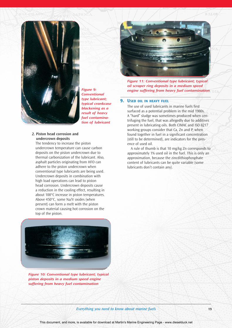
Figure 9:Conventionaltype lubricant;typical crankcaseblackening as aresult of heavyfuel contamina-tion of lubricant
2. Piston head corrosion and undercrown depositsThe tendency to increase the piston undercrown temperature can cause carbondeposits on the piston undercrown due tothermal carbonization of the lubricant. Also,asphalt particles originating from HFO canadhere to the piston undercrown when conventional type lubricants are being used.Undercrown deposits in combination withhigh load operations can lead to pistonhead corrosion. Undercrown deposits causea reduction in the cooling effect, resulting inabout 100°C increase in piston temperatures.Above 450°C, some Na/V oxides (when present) can form a melt with the pistoncrown material causing hot corrosion on thetop of the piston.
Figure 10: Conventional type lubricant; typicalpiston deposits in a medium speed engine suffering from heavy fuel contamination
Figure 11: Conventional type lubricant; typicaloil scraper ring deposits in a medium speedengine suffering from heavy fuel contamination
9. USED OIL IN HEAVY FUEL
The use of used lubricants in marine fuels first surfaced as a potential problem in the mid 1980s. A “hard” sludge was sometimes produced when cen-trifuging the fuel, that was allegedly due to additivespresent in lubricating oils. Both CIMAC and ISO 8217working groups consider that Ca, Zn and P, whenfound together in fuel in a significant concentration(still to be determined), are indicators for the pres-ence of used oil.
A rule of thumb is that 10 mg/kg Zn corresponds toapproximately 1% used oil in the fuel. This is only anapproximation, because the zincdithiophosphatecontent of lubricants can be quite variable (somelubricants don’t contain any).
19Everything you need to know about marine fuels
This document, and more, is available for download at Martin's Marine Engineering Page - www.dieselduck.net

20 Everything you need to know about marine fuels
This document, and more, is available for download at Martin's Marine Engineering Page - www.dieselduck.net
21Everything you need to know about marine fuels
Attachment I: Crude oil refiningThe purpose of crude oil refining is to convert crudeand other feedstocks into saleable products. Thedesired products are mainly gasoline, kerosene, jetfuel, gasoil and diesel.
In order to obtain these products, crude oil is firstseparated into fractions by distillation, and then thedifferent fractions are further processed in order toobtain the desired characteristics and optimum yield.
The different processes used in a modern refineryare summarized below.
1. Crude oil desaltingWater and inorganic salts are removed in an electro-static field. The main purpose of crude oil desalting isto protect the refining process units against corrosion.
2. Atmospheric distillationCrude oil is a product with a very wide boiling range.In an atmospheric distillation column the fractionsboiling below 360°C are distilled off under reflux, and,according to boiling range, recovered as naphtha,kero, and gasoil type stocks. Atmospheric distillation islimited to a maximum temperature of 360°C, becauseotherwise coking would start to occur, and this is notdesirable at this stage of crude oil refining.
3. Vacuum distillationIn order to distill off a heavier cut, without exceedingthe 360°C temperature limit, a second distillation isdone under reduced pressure: the vacuum distillation.The distillate fraction of the vacuum distillation unit isthe feedstock for a catalytic cracking unit (see item 4).
4. Catalytic cracking (e.g. fluidized bed catalytic cracking)The main feedstock for a catalytic cracker is vacuumgasoil. The cracking operation breaks large moleculesinto smaller, lighter molecules. The process runs athigh temperatures, and in the presence of the appropriate catalyst (crystalline aluminum silicate).
Atmospheric residue, with a low metal and MCRcontent, can also be used as catalytic cracker feed,necessitating an adjustment of the catalyst type.
The main purpose of a catalytic cracker is to produce light hydrocarbon fractions, which willincrease the refinery gasoline yield.
Additional streams coming from the catalytic cracker are light cycle oil (increases the gasoil pool)and heavy cycle oil (base stock for carbon black manufacturing). Both streams are also used in heavyfuel oil blending.
5. Catalytic hydrocrackingSome refineries have catalytic hydrocracking as a supplementary operation to catalytic cracking.Catalytic hydrocracking further upgrades heavy aromatic stocks to gasoline, jet fuel and gasoil typematerial. The heaviest aromatic fractions of a catcracker are the normal feedstock for a hydrocracker.
Hydrocracking requires a very high investment , butmakes the refinery yield pattern nearly independentfrom the crude oil feed.
6. VisbreakingThe feedstock of a visbreaker is the bottom productof the vacuum unit, which has an extremely high viscosity. In order to reduce that viscosity and to produce a marketable product, a relatively mild thermal cracking operation is performed. Theamount of cracking is limited by the overrulingrequirement to safeguard the heavy fuel stability.
The light product yield of the visbreaker (around20%) increases the blendstock pool for gasoil.
7. Coking (delayed coking, fluid coking, flexicoking)Coking is a very severe thermal cracking process, andcompletely destroys the residual fuel fraction. Theyield of a coker unit is lighter-range boiling material,which ultimately goes to the blending pool for thelighter products, and coke, which is essentially solidcarbon with varying amounts of impurities. Theheavier distillate fraction of a coker can be used asfeedstock for a hydrocracker (see item 5).
The above listed processes give an idea of the different type of operations done in a refinery, butmany more process units are required before the endproducts leave a refinery. Most processes improve thecharacteristics of the different refinery streams tomeet the technical requirements of the end products,others are needed to meet environmental limits(mainly sulphur reduction, both in the end-productsand in the refinery emissions).
8. Catalytic reforming and IsomerizationBoth processes are in fact catalytic reforming, andare intended to upgrade low octane naphta fractionsof the crude distillation unit into high octane components for gasoline production. The type ofcatalyst and the operating conditions determine ifthe reforming is mainly to iso-paraffins, or to aromatics. The terminology “reforming” is generallyused for the change to aromatics, while the changeto iso-paraffins is referred to as “isomerization”.Isomerization is normally done on a lighter fraction(C5/C6), while reforming is done on the heavy naphtha fraction (C7 and heavier, up to 150°C).
9. AlkylationThis is another process intended to increase the yield of valuable gasoline blend components.Alkylation is a catalyst steered combination reactionof low molecular weight olefins with an iso-paraffinto form higher molecular weight iso-paraffins. Thefeed to the alkylation unit is C3 and C4s from the catalytic cracker unit, and iso-butane.
Attachments
This document, and more, is available for download at Martin's Marine Engineering Page - www.dieselduck.net
22 Everything you need to know about marine fuels
10. HydrotreatingA hydrotreating process is, as the name indicates, a process, which uses hydrogen to remove impuritiesfrom product streams, and replaces them with hydrogen. Hydrotreating is generally used to remove sulphur (re very low sulphur limits in thespecifications of gasoline and gasoil) and is thencalled hydro-desulphurization. It is a catalyticprocess. The process is generally used on keroseneand gasoil fractions. Residual hydro-desulphurizationis an existing process, and is in theory feasible, butthe economics are not favorable.
11. MeroxA merox unit is used on naphtha and kerosenestreams. It is a catalytic process which is not intended to remove the sulphur from the stream, but to convert mercaptan sulphur type molecules(corrosive, and with a very obnoxious smell) intodisulphide type molecules.
12. Sulphur recoveryAs a result of the removal of sulphur from the refinery streams by hydrotreating, the generation ofhydrogen sulphide during cracking and coking, refinery gases contain a very high concentration ofhydrogen sulphide. The simple solution to eliminatethe hydrogen sulphide (extremely toxic) is to burn it,but this then generates SO2, which contributes toacidification problems. In order to safeguard theenvironment, the hydrogen sulphide is converted inrefineries to elemental sulphur. This is typicallyaccomplished by extracting the hydrogen sulphidefrom the refinery gas by a chemical solvent, e.g. anaqueous amine solution. The rich solution is thenpreheated and stripped by steam. The Claus processconsists of the partial combustion of the hydrogensulphide rich gas stream (sufficient air is introducedto combust 1/3 of the H2S to SO2). This SO2 then reacts(under influence of a catalyst) with H2S in the orderof 1 SO2 for 2 H2S, and thus provides elemental sulphur. The tail gas of the Claus unit is still rich inSO2, and environmental legislation can require thefurther clean-up of this tail gas.
This document, and more, is available for download at Martin's Marine Engineering Page - www.dieselduck.net
23Everything you need to know about marine fuels
Attachment II: Reproducibility (R) ofmarine fuel test methods
Density at 15°C, kg/m3
ISO 3675– For transparent, non viscous products:
R = 1.2 kg/m3 or 0.0012 kg/l– For opaque products:
R = 1.5 kg/m3 or 0.0015 kg/l
ISO 12185– For transparent middle distillates:
R = 0.5 kg/m3 or 0.0005 kg/l– For crude oils and other petroleum products:
R = 1.5 kg/m3 or 0.0015 kg/l
Kinematic viscosity, mm2/sISO 3104Heavy fuels: at 50°C : R = 0.074 χ
at 100°C : R = 0.04 (χ + 8)Where χ is the average of the results being compared
Flash point, P.M., closed testerISO 2719For flash point < 104°C: R = 3.5°CFor flash point > 104°C: R = 8.5°C
Pour Point, °CISO 3016R = 6.59°C
Cloud Point, °CISO 3015For distillate fractions: R = 4°C
Sulphur, % (m/m)ISO 8754R = 0.055 (χ + 0.8) where χ is the mean sulphur content
Cetane index (4 variable equation)ISO 4264Precision is dependent on the precision ofthe original density and distillation recoverytemperature determinations that enter intothe calculation.
Micro carbon residue, % (m/m)ISO 10370R = χ2/3 × 0.2451Where χ is the average of the results being compared
Ash, % (m/m)ISO 6245
For ash content between 0.001 and 0.079 wt%: R = 0.005For ash content between 0.080 and 0.180 wt%: R = 0.024
Sediment by extraction, % (m/m)ISO 3735R = 0.033 + 0.255 χWhere χ is the average result in percent
Total existent sediment, % (m/m)ISO 10307-1Heavy fuels: R = 0.341 √χDistillate fuels containing heavy components:R = 0.174 √χWhere χ is the average of the test results in %(m/m)
Total sediment, potential aging, % (m/m)ISO 10307-2Heavy fuels: R = 0.341 √χDistillate fuels containing heavy components:R = 0.174 √χWhere χ is the average of the test results in % (m/m)
Water, % (v/v)ISO 3733– Water collected between 0.0 and 1.0 ml:
R = 0.2 ml– Water collected between 1.1 and 25 ml:
R = 0.2 ml or 10% of mean, whichever is greater
Vanadium, mg/kgISO 14597– The method is applicable to products having
V content in the range of 5 to 1000 mg/kg,although reproducibility data have only beendetermined up to 100 mg/kg for VFor V content between 5 and 30 mg/kg: R = 5 mg/kgFor V content between 31 and 100 mg/kg: R = 10 mg/kg
Cat fines Al+Si, mg/kgISO 10478ICP detection: Al: R = 0.337 χ
Si: R = 0.332 χAAS detection: Al: R = 0.7890 χ2/3
Si: R = 1.388 χ2/3
Where χ is the average result in mg/kg
This document, and more, is available for download at Martin's Marine Engineering Page - www.dieselduck.net
Attachment III: Gas turbine fuel requirements
Most heavy-duty gas turbines operate on natural gas and distillate fuels.
Gas turbines operating on natural gas require minimum fuel treatment. Distillate fuels, immediately after refining, have no, or extremely low contamination levels of water, solids and tracemetals. Contamination (mainly by water) duringtransport can not be excluded, and centrifuging is the best method for the removal of water and solids (can contain sodium salts). Sodium salts arevery detrimental for gas turbines, and seawater contamination must be completely removed.
Gas turbine manufacturers have also developedefficient technologies for gas turbine operation withash forming fuels (e.g. heavy fuels), as a cost-effectiveoption against gasoil for sites where natural gas will not be available in the foreseeable future.
The use of heavy fuels requires that utmost attention be paid to two types of potential hot path corrosion:
• Sulphidation corrosion, caused by alkaline sulphates (mainly Na2SO4).
• Vanadic corrosion, caused by low melting vanadium oxides (V2O5).
Sulphidation corrosion is avoided by removing thesodium and potassium from the fuel by stringentwater washing up to the level Na+K < 1 mg/kg.
Vanadic corrosion is counteracted by the additionof magnesium additives to the fuel from the moment V > 0.5 mg/kg. The complex oxides between Mg and V which are then formed, are nolonger corrosive (traditionally, a m/m ratio Mg/V of three is adhered to).
Heavy-duty gas turbines have been operating satisfactorily on ash forming fuels since mid-1980s. It is clear that the need for magnesium additivationto combat vanadic corrosion imposes a technical and economical upper limit on the vanadium content of the fuel.
24 Everything you need to know about marine fuels
This document, and more, is available for download at Martin's Marine Engineering Page - www.dieselduck.net
Alfa Laval, Technical information, “ALCAP, Cleaning system for fuel oil”.
CIMAC, “Recommendations regarding fuel requirements for diesel engines”, number 11, 1990.
Gary, J. H., Handwerk, G. E., “Petroleum refining,Technology and Economics”, 2nd edition, Revisedand Expanded.
ISO 8217:1996, “Petroleum products — Fuels (class F) — Specifications of marine fuels.
Mansoori, G.A., “Arterial blockage/fouling in petroleum and natural gas industries(asphaltene/bitumen, resin..)”, University Illinois-Chicago/Thermodynamics research Laboratory.
Molière, M., Gazonnet, J.P., Vivicorsi, J.P., “EGTExperience with gas turbines burning ash-formingfuels”, GEC ALSTHOM Technical review, 1993, N°.11.
Selley, R. C., “Elements of petroleum geology”, 2nd edition.
Verhelst, A., “Latest developments in marine lubrication technology”, Texaco Technology Ghent.
VOS, Publication Stichting VOS
Table 1 – Requirements for marine distillate fuels,and Table 2 – Requirements for marine residual fuels,taken from ISO 8217:1996, have been reproduced withthe permission of the International Organization forStandardization, ISO. This standard can be obtainedfrom any member body or directly from the CentralSecretariat, ISO, Case postal 56, 1211 Geneva 20,Switzerland. Copyright remains with ISO.
25Everything you want to know about fuels
References
This document, and more, is available for download at Martin's Marine Engineering Page - www.dieselduck.net

Notes
This document, and more, is available for download at Martin's Marine Engineering Page - www.dieselduck.net
Marine LubricantsFAMM is one of the largest suppliers of marinelubricants in the world. FAMM has a superior line ofmarine lubricants based upon proven experienceof both parent companies, Texaco and Chevron.In addition to superior products, our seasonedmarine professionals and technical support staff,including laboratories in Rotterdam and Ghent,offer you the best service and support available.
The CompanyFuel and Marine Marketing LLC (FAMM), wasformed November 1, 1998 by Texaco andChevron, combining the global residual fuel and marine lubricants marketing businesses of both companies.
Industrial ProductsFAMM’s industrial customers include power plants throughout theUnited States, Latin America, Europe and Asia that have learned torely on us to deliver their fuels and lubricants on time and on spec.
Marine FuelsFAMM is a premier supplier of marine fuels worldwide, offering consistently high quality products with timely delivery and serv-ice. Additionally, FAMM offers price risk management alterna-tives for your fuel needs. FAMM has a vast network of supply –including Texaco, Chevron and Caltex fuels – to meet yourrequirements. Make FAMM your first choice for marine fuels.
Marine CoolantsFAMM has just advanced the technical frontiers in marine coolants withHavoline XLI Extended Life Coolant. Havoline XLI provides maximum protectionand lasts longer than traditional technologies in your marine or power genera-tion system. Havoline XLI combines superior performance with long life econo-my to keep your engines running smoothly for years.
For further information contact your local FAMM representative.
Together to serve you betterA Texaco and Chevron Joint Venture Company
Visit us on the web at www.fammllc.com
This document, and more, is available for download at Martin's Marine Engineering Page - www.dieselduck.net

Fuel and Marine Marketing Limited1 Westferry Circus, Canary Wharf
London E14 4HAUnited Kingdom
Tel: +44 20 7719 3883Fax: +44 20 7719 5182
Fuel and Marine Marketing LLC2000 Westchester Avenue
White Plains, New York 10650United States of AmericaTel: +1 914 253 4500Fax: +1 914 253 7111
Fuel and Marine Marketing LLC350 Orchard Road, #21-01
Shaw House 238868Singapore
Tel: +65 7300 300Fax: +65 7300 333
Regional Marketing Locations
Visit us at www.fammllc.com
M039
This document, and more, is available for download at Martin's Marine Engineering Page - www.dieselduck.net