evannex - lighted emblem installation guide for tesla model s
TRANSCRIPT
Gen II Tesla Model S Lighted Rear Applique Installation Instructions
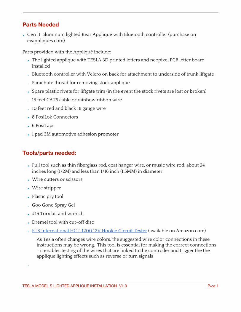
Parts Needed
• Gen II aluminum lighted Rear Appliqué with Bluetooth controller (purchase on evappliques.com)
Parts provided with the Appliqué include:
• The lighted applique with TESLA 3D printed letters and neopixel PCB letter board installed
• Bluetooth controller with Velcro on back for attachment to underside of trunk liftgate
• Parachute thread for removing stock applique
• Spare plastic rivets for liftgate trim (in the event the stock rivets are lost or broken)
• 15 feet CAT6 cable or rainbow ribbon wire
• 10 feet red and black 18 gauge wire
• 8 PosiLok Connectors
• 6 PosiTaps
• 1 pad 3M automotive adhesion promoter
Tools/parts needed:
• Pull tool such as thin fiberglass rod, coat hanger wire, or music wire rod, about 24 inches long (1/2M) and less than 1/16 inch (1.5MM) in diameter.
• Wire cutters or scissors
• Wire stripper
• Plastic pry tool
• Goo Gone Spray Gel
• #15 Torx bit and wrench
• Dremel tool with cut-off disc
• ETS International HCT-1200 12V Hookie Circuit Tester (available on Amazon.com)
As Tesla often changes wire colors, the suggested wire color connections in these instructions may be wrong. This tool is essential for making the correct connections - it enables testing of the wires that are linked to the controller and trigger the the applique lighting effects such as reverse or turn signals
•
TESLA MODEL S LIGHTED APPLIQUE INSTALLATION V1.3 PAGE 1
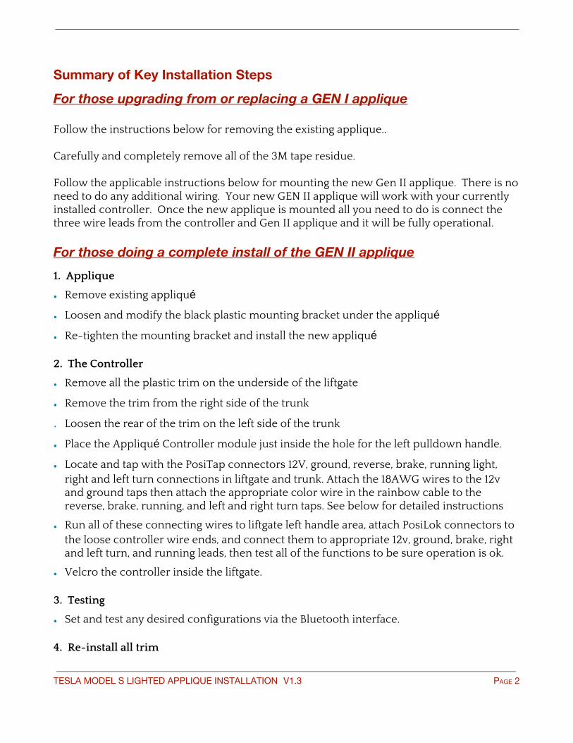
Summary of Key Installation Steps
For those upgrading from or replacing a GEN I applique Follow the instructions below for removing the existing applique.. Carefully and completely remove all of the 3M tape residue. Follow the applicable instructions below for mounting the new Gen II applique. There is no need to do any additional wiring. Your new GEN II applique will work with your currently installed controller. Once the new applique is mounted all you need to do is connect the three wire leads from the controller and Gen II applique and it will be fully operational. For those doing a complete install of the GEN II applique
1. Applique
• Remove existing appliqué
• Loosen and modify the black plastic mounting bracket under the appliqué
• Re-tighten the mounting bracket and install the new appliqué
2. The Controller
• Remove all the plastic trim on the underside of the liftgate
• Remove the trim from the right side of the trunk
• Loosen the rear of the trim on the left side of the trunk
• Place the Appliqué Controller module just inside the hole for the left pulldown handle.
• Locate and tap with the PosiTap connectors 12V, ground, reverse, brake, running light, right and left turn connections in liftgate and trunk. Attach the 18AWG wires to the 12v and ground taps then attach the appropriate color wire in the rainbow cable to the reverse, brake, running, and left and right turn taps. See below for detailed instructions
• Run all of these connecting wires to liftgate left handle area, attach PosiLok connectors to the loose controller wire ends, and connect them to appropriate 12v, ground, brake, right and left turn, and running leads, then test all of the functions to be sure operation is ok.
• Velcro the controller inside the liftgate. 3. Testing
• Set and test any desired configurations via the Bluetooth interface. 4. Re-install all trim
TESLA MODEL S LIGHTED APPLIQUE INSTALLATION V1.3 PAGE 2
Note: If you are doing the installation yourself you may want to review these supplemental installation notes provided by JPP.
TESLA MODEL S LIGHTED APPLIQUE INSTALLATION V1.3 PAGE 3
A. Mount the Appliqué
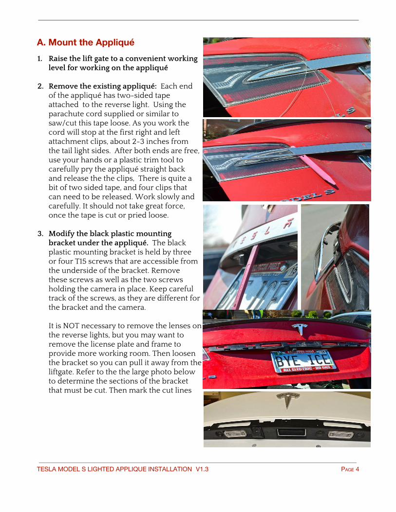
1. Raise the lift gate to a convenient working level for working on the appliqué
2. Remove the existing appliqué: Each end of the appliqué has two-sided tape attached to the reverse light. Using the parachute cord supplied or similar to saw/cut this tape loose. As you work the cord will stop at the first right and left attachment clips, about 2-3 inches from the tail light sides. After both ends are free, use your hands or a plastic trim tool to carefully pry the appliqué straight back and release the the clips, There is quite a bit of two sided tape, and four clips that can need to be released. Work slowly and carefully. It should not take great force, once the tape is cut or pried loose.
3. Modify the black plastic mounting bracket under the appliqué. The black plastic mounting bracket is held by three or four T15 screws that are accessible from the underside of the bracket. Remove these screws as well as the two screws holding the camera in place. Keep careful track of the screws, as they are different for the bracket and the camera. It is NOT necessary to remove the lenses on the reverse lights, but you may want to remove the license plate and frame to provide more working room. Then loosen the bracket so you can pull it away from the liftgate. Refer to the the large photo below to determine the sections of the bracket that must be cut. Then mark the cut lines
TESLA MODEL S LIGHTED APPLIQUE INSTALLATION V1.3 PAGE 4
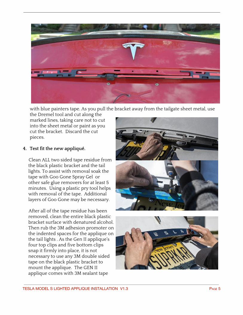
with blue painters tape. As you pull the bracket away from the tailgate sheet metal, use the Dremel tool and cut along the marked lines, taking care not to cut into the sheet metal or paint as you cut the bracket. Discard the cut pieces.
4. Test fit the new appliqué.
Clean ALL two sided tape residue from the black plastic bracket and the tail lights. To assist with removal soak the tape with Goo Gone Spray Gel or other safe glue removers for at least 5 minutes. Using a plastic pry tool helps with removal of the tape. Additional layers of Goo Gone may be necessary. After all of the tape residue has been removed, clean the entire black plastic bracket surface with denatured alcohol. Then rub the 3M adhesion promoter on the indented spaces for the applique on the tail lights . As the Gen II applique’s four top clips and five bottom clips snap it firmly into place, it is not necessary to use any 3M double sided tape on the black plastic bracket to mount the applique. The GEN II applique comes with 3M sealant tape
TESLA MODEL S LIGHTED APPLIQUE INSTALLATION V1.3 PAGE 5

on the end. This will be used to make a more secure connection of the ends to the taillights If you’ve detached the camera from the bracket, use the original screws to tighten down the camera and applique bracket. The connecting cable of the appliqué is inserted into the rectangular opening in the bracket closest to the cable position itself (that opening goes through the entire liftgate shell and make the cable available from the interior side of the liftgate). There are two methods for final mounting of the applique, as described below. Method 1: Work from left to right. Remove the red 3M tape liner from all of the tape on the two applique ends. Insert the power cord into the trunk, pull the cable into the trunk as you start to align the applique . Then align the four upper clips in their respective slots on the liftgate but do not snap them into place. Take care to not let the tape on the two ends touch the tail lights. When you are satisfied with the alignment start with the left end of the applique and push it firmly onto the tail light so the tape adheres. Then working from the left side, snap the four upper clips into place firmly, finishing by placing the right side end firmly onto the tail light until the 3M tape adheres. Then using firm pressure make sure the lower and upper clips are also snapped into place. Method 2: Align and snap into place the four upper clips Remove the red 3M tape liner from all of the tape on the two applique ends. Then align the four upper clips in their respective slots on the liftgate but do not snap them into place. Take care to not let the tape on the two ends touch the tail lights. When you are satisfied with the alignment snap the four upper clips into place firmly. The check the alignment of each end and push the them firmly into place on the tail lights so the 3M tape adheres. Then using firm pressure make sure the lower clips are also snapped into place.
For now this completes the work on the outside of the car. Time to move inside.
TESLA MODEL S LIGHTED APPLIQUE INSTALLATION V1.3 PAGE 6
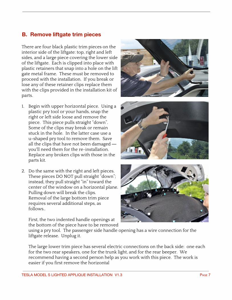
B. Remove liftgate trim pieces There are four black plastic trim pieces on the interior side of the liftgate: top, right and left sides, and a large piece covering the lower side of the liftgate. Each is clipped into place with plastic retainers that snap into a hole on the lift gate metal frame. These must be removed to proceed with the installation. If you break or lose any of these retainer clips replace them with the clips provided in the installation kit of parts. 1. Begin with upper horizontal piece. Using a
plastic pry tool or your hands, snap the right or left side loose and remove the piece. This piece pulls straight “down”. Some of the clips may break or remain stuck in the hole. In the latter case use a u-shaped pry tool to remove them. Save all the clips that have not been damaged — you’ll need them for the re-installation. Replace any broken clips with those in the parts kit.
2. Do the same with the right and left pieces.
These pieces DO NOT pull straight “down”; instead, they pull straight “in” toward the center of the window on a horizontal plane. Pulling down will break the clips. Removal of the large bottom trim piece requires several additional steps, as follows.. First, the two indented handle openings at the bottom of the piece have to be removed using a pry tool. The passenger side handle opening has a wire connection for the liftgate release. Unplug it. The large lower trim piece has several electric connections on the back side: one each for the two rear speakers, one for the trunk light, and for the rear beeper. We recommend having a second person help as you work with this piece. The work is easier if you first remove the horizontal
TESLA MODEL S LIGHTED APPLIQUE INSTALLATION V1.3 PAGE 7
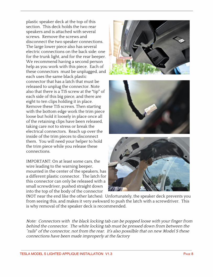
plastic speaker deck at the top of this section. This deck holds the two rear speakers and is attached with several screws. Remove the screws and disconnect the two speaker connections. The large lower piece also has several electric connections on the back side: one for the trunk light, and for the rear beeper. We recommend having a second person help as you work with this piece. Each of these connectors must be unplugged, and each uses the same black plastic connector that has a latch that must be released to unplug the connector. Note also that there is a T15 screw at the “tip” of each side of this big piece, and there are eight to ten clips holding it in place. Remove these T15 screws. Then starting with the bottom edge work the trim piece loose but hold it loosely in place once all of the retaining clips have been released, taking care not to stress or break the electrical connectors. Reach up over the inside of the trim pieces to disconnect them. You will need your helper to hold the trim piece while you release these connections. IMPORTANT: On at least some cars, the wire leading to the warning beeper, mounted in the center of the speakers, has a different plastic connector. The latch for this connector can only be released with a small screwdriver, pushed straight down into the top of the body of the connector (NOT near the end like the other latches). Unfortunately, the speaker deck prevents you from seeing this, and makes it very awkward to push the latch with a screwdriver. This is why removal of the speaker deck is recommended. Note: Connectors with the black locking tab can be popped loose with your finger from behind the connector. The white locking tab must be pressed down from between the “rails” of the connector, not from the rear. It’s also possilble that on new Model S these connections have been made improperly at the factory
TESLA MODEL S LIGHTED APPLIQUE INSTALLATION V1.3 PAGE 8

3. When the pieces have been removed you may see (depending on your car) two black vinyl sheets on the back of the lift gate. These are glued on with a tar-like material and need to be removed to provide access to the electrical connections. Remove them and set aside.
4. Once all of the trim pieces have been removed set them aside in a safe place and keep all of the retainers and screws in a place where they will be easy to find for reuse. Replace any broken plastic clips.
C. Install the Bluetooth controller and make the power supply, brake, reverse, turn signal, and running light connections
TESLA MODEL S LIGHTED APPLIQUE INSTALLATION V1.3 PAGE 9
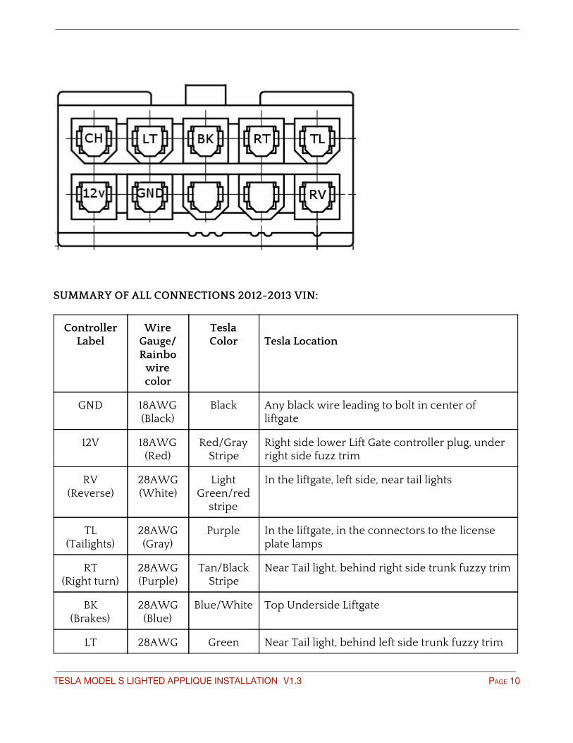
SUMMARY OF ALL CONNECTIONS 2012-2013 VIN:
Controller Label
Wire Gauge/ Rainbo
wire color
Tesla Color
Tesla Location
GND 18AWG (Black)
Black Any black wire leading to bolt in center of liftgate
12V 18AWG (Red)
Red/Gray Stripe
Right side lower Lift Gate controller plug, under right side fuzz trim
RV (Reverse)
28AWG (White)
Light Green/red
stripe
In the liftgate, left side, near tail lights
TL (Tailights)
28AWG (Gray)
Purple In the liftgate, in the connectors to the license plate lamps
RT (Right turn)
28AWG (Purple)
Tan/Black Stripe
Near Tail light, behind right side trunk fuzzy trim
BK (Brakes)
28AWG (Blue)
Blue/White Top Underside Liftgate
LT 28AWG Green Near Tail light, behind left side trunk fuzzy trim
TESLA MODEL S LIGHTED APPLIQUE INSTALLATION V1.3 PAGE 10
(Left turn) (Green)
CH 28AWG (yellow)
N/A Future Expansion.
SUMMARY OF ALL CONNECTIONS 2014 and 2015 VIN:
Controller Label
Wire Gauge
Tesla Color
Tesla Location
GND 18AWG (Black)
Bolt Any black wire leading to bolt in center of liftgate
12V 18AWG (Red)
Red/Gray Pin 8 of Tesla Liftgate Control Module
RV (Reverse)
28AWG (White)
Gray/White In the liftgate, left side, near lights
TL (Tailights)
28AWG (Gray)
Dark Brown/Pink
In the liftgate, in the connectors to the license plate lamps
RT (Right turn)
28AWG (Purple)
Tan/Black Near Tail light, behind right side trunk fuzzy trim
BK (Brakes)
28AWG (Blue)
White Near hingeline/rubber tube.
LT (Left turn)
28AWG (Green)
Red Near Tail light, behind left side trunk fuzzy trim
CH 28AWG N/A Future Expansion.
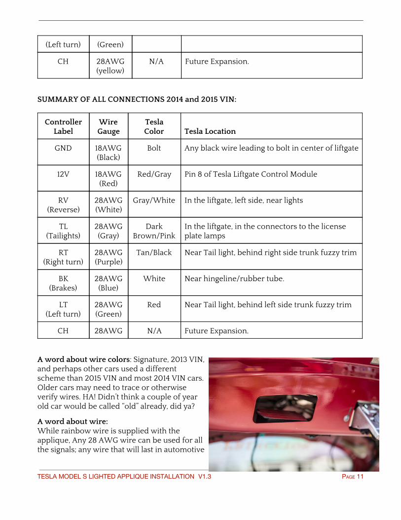
A word about wire colors: Signature, 2013 VIN, and perhaps other cars used a different scheme than 2015 VIN and most 2014 VIN cars. Older cars may need to trace or otherwise verify wires. HA! Didn’t think a couple of year old car would be called “old” already, did ya?
A word about wire: While rainbow wire is supplied with the applique, Any 28 AWG wire can be used for all the signals; any wire that will last in automotive
TESLA MODEL S LIGHTED APPLIQUE INSTALLATION V1.3 PAGE 11
use. The main 12V wire and Ground wire MUST be 18AWG at minimum. Your appliqué will do funky things if the voltage is “almost good enough”. DO NOT use anything less than 18AWG for the 12V power and ground connections. For effective threading and connections of the ribbon cable you may have to separate individual leads in the cable which is easily done by just using a razor knfe to separate them at the ends then carefully pulling them apart..
UPPER LEVEL TAILGATE CONNECTIONS
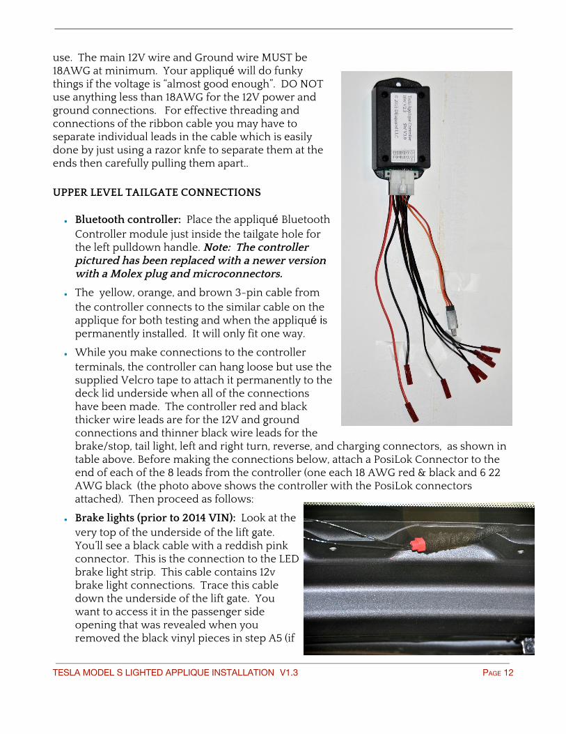
• Bluetooth controller: Place the appliqué Bluetooth Controller module just inside the tailgate hole for the left pulldown handle. Note: The controller pictured has been replaced with a newer version with a Molex plug and microconnectors.
• The yellow, orange, and brown 3-pin cable from the controller connects to the similar cable on the applique for both testing and when the appliqué is permanently installed. It will only fit one way.
• While you make connections to the controller terminals, the controller can hang loose but use the supplied Velcro tape to attach it permanently to the deck lid underside when all of the connections have been made. The controller red and black thicker wire leads are for the 12V and ground connections and thinner black wire leads for the brake/stop, tail light, left and right turn, reverse, and charging connectors, as shown in table above. Before making the connections below, attach a PosiLok Connector to the end of each of the 8 leads from the controller (one each 18 AWG red & black and 6 22 AWG black (the photo above shows the controller with the PosiLok connectors attached). Then proceed as follows:
• Brake lights (prior to 2014 VIN): Look at the very top of the underside of the lift gate. You’ll see a black cable with a reddish pink connector. This is the connection to the LED brake light strip. This cable contains 12v brake light connections. Trace this cable down the underside of the lift gate. You want to access it in the passenger side opening that was revealed when you removed the black vinyl pieces in step A5 (if
TESLA MODEL S LIGHTED APPLIQUE INSTALLATION V1.3 PAGE 12
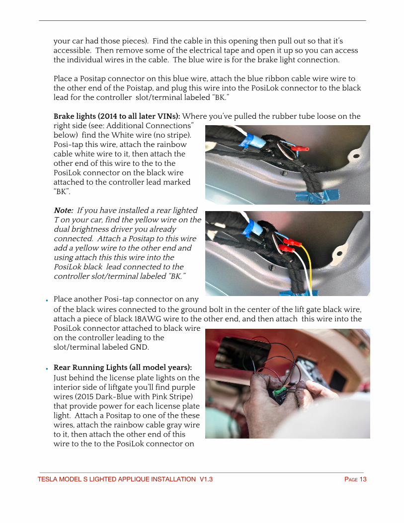
your car had those pieces). Find the cable in this opening then pull out so that it’s accessible. Then remove some of the electrical tape and open it up so you can access the individual wires in the cable. The blue wire is for the brake light connection. Place a Positap connector on this blue wire, attach the blue ribbon cable wire wire to the other end of the Poistap, and plug this wire into the PosiLok connector to the black lead for the controller slot/terminal labeled “BK.” Brake lights (2014 to all later VINs): Where you’ve pulled the rubber tube loose on the right side (see: Additional Connections” below) find the White wire (no stripe). Posi-tap this wire, attach the rainbow cable white wire to it, then attach the other end of this wire to the to the PosiLok connector on the black wire attached to the controller lead marked “BK”. Note: If you have installed a rear lighted T on your car, find the yellow wire on the dual brightness driver you already connected. Attach a Positap to this wire add a yellow wire to the other end and using attach this this wire into the PosiLok black lead connected to the controller slot/terminal labeled “BK.”
• Place another Posi-tap connector on any of the black wires connected to the ground bolt in the center of the lift gate black wire, attach a piece of black 18AWG wire to the other end, and then attach this wire into the PosiLok connector attached to black wire on the controller leading to the slot/terminal labeled GND.
• Rear Running Lights (all model years): Just behind the license plate lights on the interior side of liftgate you’ll find purple wires (2015 Dark-Blue with Pink Stripe) that provide power for each license plate light. Attach a Positap to one of the these wires, attach the rainbow cable gray wire to it, then attach the other end of this wire to the to the PosiLok connector on
TESLA MODEL S LIGHTED APPLIQUE INSTALLATION V1.3 PAGE 13

the black wire attached to the controller lead marked “TL”.
• Reverse lights (prior to 2014 VIN): In the cable bundle that connects to the left rear running lights, find the Light Green wire with the Red stripe. Posi-tap this wire, attach the rainbow cable white wire to it, then attach the other end of this wire to the to the PosiLok connector on the black wire attached to the controller lead marked “RV”.
• Reverse lights (2014 and 2015 VIN): In the cable bundle that connects to the left rear running lights, find the Grey wire with the White stripe. Posi-tap this wire, attach the rainbow cable white wire to it, then attach the other end of this wire to the to the PosiLok connector on the black wire attached to the controller lead marked “RV”. Note: Some European cars have one “Reverse” light and one “Rear facing fog lamp” on the other side. Tap into whichever one you wish to trigger the Tesla Applique to light up bright white.
LOWER LEVEL TRUNK CONNECTIONS 1. Fold down the right rear seat. Remove
the cargo shelf. Look under the passenger and driver side hard plastic ledges that support the cargo shelf. There is one #15 Torx screw on each. Remove them. Then remove the entire ledge assemblies by prying or pulling them toward the center of the car. There are multiple clips and a fairly large force is required to get them to release.
2. There is one press-in tab black plastic
button holding each fender well fuzzy lining. Remove them, and then remove the entire linings on both sides. As an option, to locate and tap the left rear turn signal you may be able to save some time by pulling the driver’s side fuzzy lining away near the tail light. There is one wire on each lining to disconnect for the rear trunk light, with a latching connector. Removal of these trim pieces will reveal all the wiring on the right and left sides of the trunk.. The car in the
TESLA MODEL S LIGHTED APPLIQUE INSTALLATION V1.3 PAGE 14
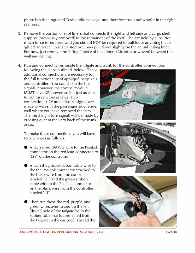
photo has the upgraded Tesla audio package, and therefore has a subwoofer in the right rear area.
3. Remove the portion of roof liners that connects the right and left side and cargo shelf support (previously removed) to the remainder of the roof. The are held by clips. Not much force is required, and you should NOT be required to pull loose anything that is “glued” in place. In a later step, you may pull down slightly on the actual ceiling liner. For now, just remove the “bridge” piece of headliners (Alcantra or woven) between the wall and ceiling.
4. Run and connect wires inside the liftgate and trunk for the controller connections following the steps outlined below. These additional connections are necessary for the full functionality of appliqué neopixels and controller. You could skip the turn signals; however, the control module MUST have 12V power, so it is just as easy to run three wires at once. Two connections (12V and left turn signal) are made to wires in the passenger side fender well where you have removed the trim. The third (right turn signal) will be made by crossing over at the very back of the trunk areas. To make these connections you will have to run wires as follows: ● Attach a red 18AWG wire to the PosiLok
connector on the red lead connected to “12V” on the controller
● Attach the purple ribbon cable wire to the the PosiLok connector attached to the black wire from the controller labeled “RT” and the green ribbon cable wire to the PosiLok connector on the black wire from the controller labeled “LT”.
● Then run these the red, purple, and green wires over to and up the left (driver) side of the tailgate lid to the rubber tube that is connected from the tailgate to the car roof. Thread the
TESLA MODEL S LIGHTED APPLIQUE INSTALLATION V1.3 PAGE 15
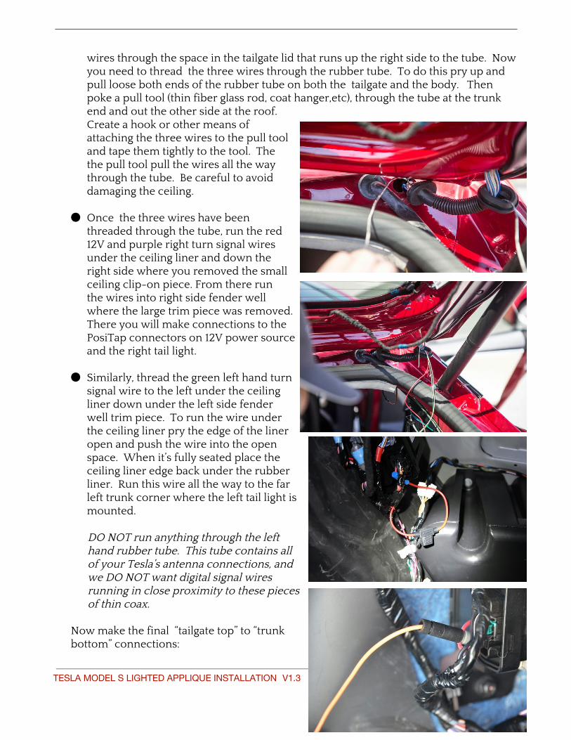
wires through the space in the tailgate lid that runs up the right side to the tube. Now you need to thread the three wires through the rubber tube. To do this pry up and pull loose both ends of the rubber tube on both the tailgate and the body. Then poke a pull tool (thin fiber glass rod, coat hanger,etc), through the tube at the trunk end and out the other side at the roof. Create a hook or other means of attaching the three wires to the pull tool and tape them tightly to the tool. The the pull tool pull the wires all the way through the tube. Be careful to avoid damaging the ceiling.
● Once the three wires have been threaded through the tube, run the red 12V and purple right turn signal wires under the ceiling liner and down the right side where you removed the small ceiling clip-on piece. From there run the wires into right side fender well where the large trim piece was removed. There you will make connections to the PosiTap connectors on 12V power source and the right tail light.
● Similarly, thread the green left hand turn
signal wire to the left under the ceiling liner down under the left side fender well trim piece. To run the wire under the ceiling liner pry the edge of the liner open and push the wire into the open space. When it’s fully seated place the ceiling liner edge back under the rubber liner. Run this wire all the way to the far left trunk corner where the left tail light is mounted.
DO NOT run anything through the left hand rubber tube. This tube contains all of your Tesla’s antenna connections, and we DO NOT want digital signal wires running in close proximity to these pieces of thin coax.
Now make the final “tailgate top” to “trunk bottom” connections:
TESLA MODEL S LIGHTED APPLIQUE INSTALLATION V1.3 PAGE 16
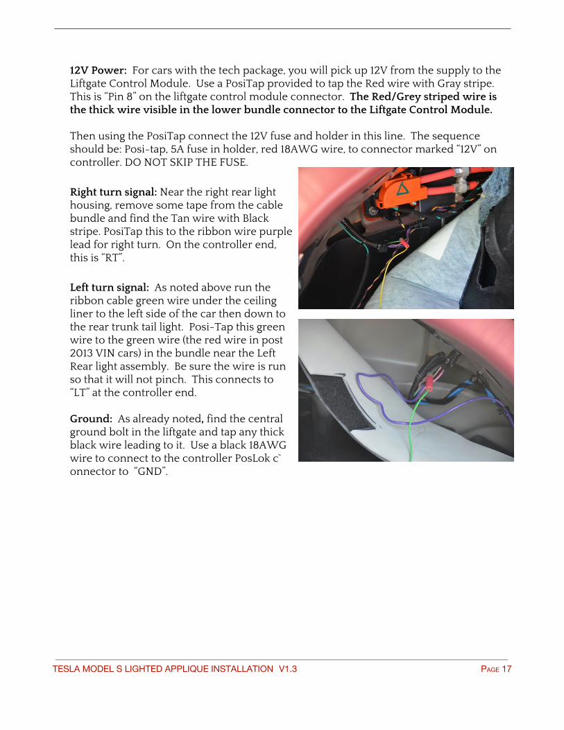
12V Power: For cars with the tech package, you will pick up 12V from the supply to the Liftgate Control Module. Use a PosiTap provided to tap the Red wire with Gray stripe. This is “Pin 8” on the liftgate control module connector. The Red/Grey striped wire is the thick wire visible in the lower bundle connector to the Liftgate Control Module. Then using the PosiTap connect the 12V fuse and holder in this line. The sequence should be: Posi-tap, 5A fuse in holder, red 18AWG wire, to connector marked “12V” on controller. DO NOT SKIP THE FUSE.
Right turn signal: Near the right rear light housing, remove some tape from the cable bundle and find the Tan wire with Black stripe. PosiTap this to the ribbon wire purple lead for right turn. On the controller end, this is “RT”.
Left turn signal: As noted above run the ribbon cable green wire under the ceiling liner to the left side of the car then down to the rear trunk tail light. Posi-Tap this green wire to the green wire (the red wire in post 2013 VIN cars) in the bundle near the Left Rear light assembly. Be sure the wire is run so that it will not pinch. This connects to “LT” at the controller end. Ground: As already noted, find the central ground bolt in the liftgate and tap any thick black wire leading to it. Use a black 18AWG wire to connect to the controller PosLok c`onnector to “GND”.
TESLA MODEL S LIGHTED APPLIQUE INSTALLATION V1.3 PAGE 17
D. Testing Basic Operation and Permanent Installation of Applique Before reassembly the trunk and liftgate components you must test the factory set operations of the applique. This is to confirm that you have made all of the connections correctly before reinstalling the liftgate trim and customizing the Bluetooth settings. To complete the test place the applique loosely into place on the bracket. Run its connecting cable through the opening in the liftgate and connect to the controller. the controller will now have power to operate. With a helper confirm the following:
• The appliqué lights red when you turn on the car and the parking/tail lights.
• The appliqué turns bright red when you press the brakes
• The appliqué letters sequence from left to right when you turn on the right turn signal
• The appliqué letters sequence from right to left when you turn on the left turn signal
• The appliqué lights white when you put the car into reverse
• With the parking lights off, the same functions will occur, but will light/sequence directly from ‘off’ to ‘bright red’.
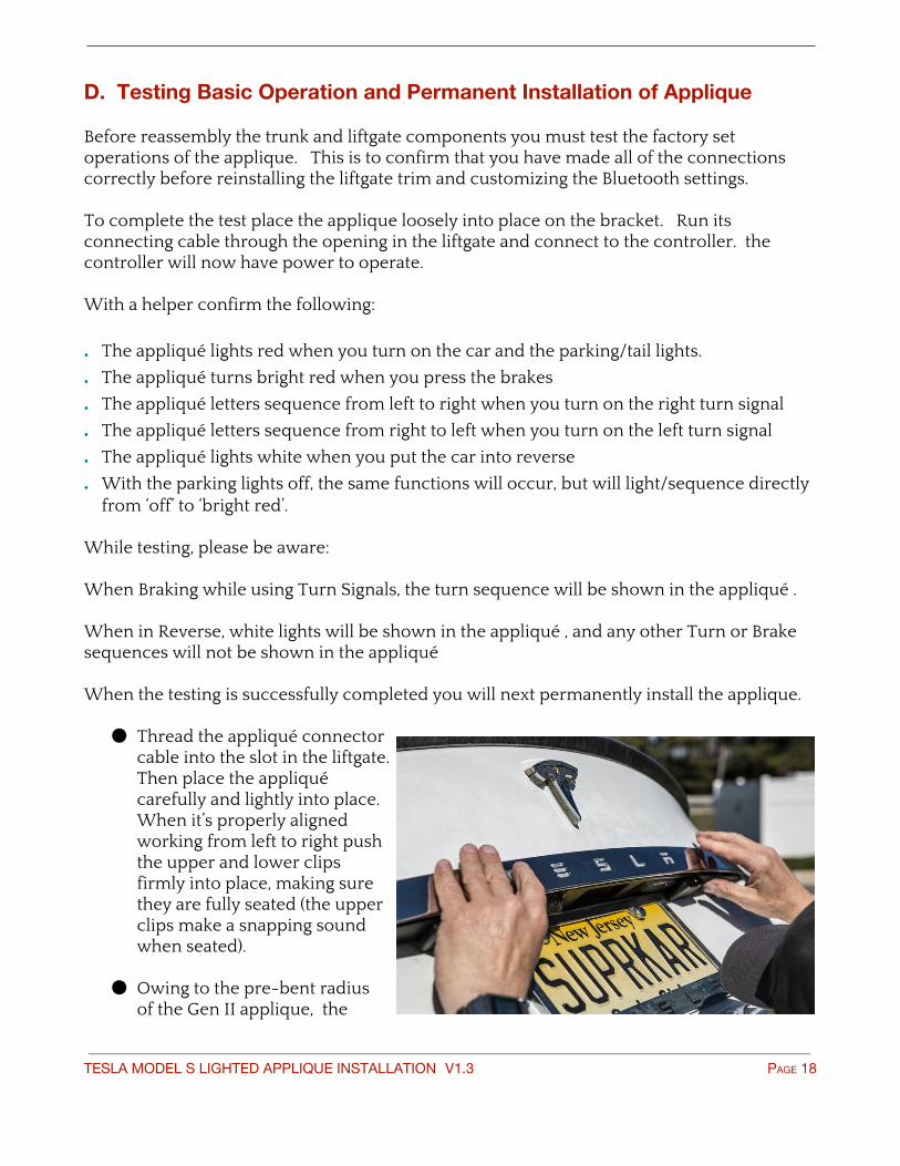
While testing, please be aware: When Braking while using Turn Signals, the turn sequence will be shown in the appliqué . When in Reverse, white lights will be shown in the appliqué , and any other Turn or Brake sequences will not be shown in the appliqué When the testing is successfully completed you will next permanently install the applique.
● Thread the appliqué connector cable into the slot in the liftgate. Then place the appliqué carefully and lightly into place. When it’s properly aligned working from left to right push the upper and lower clips firmly into place, making sure they are fully seated (the upper clips make a snapping sound when seated).
● Owing to the pre-bent radius of the Gen II applique, the
TESLA MODEL S LIGHTED APPLIQUE INSTALLATION V1.3 PAGE 18
ends over the taillights should be firmly seated.
● Before reassembling the trunk and liftgate components double check operation of the applique one more time.
E. Reinstall all trunk and liftgate trim pieces Working in reverse order, re-install first the two large fuzzy fender well liner pieces, then the plastic parcel shelf ledges, followed by two two roof liner pieces. Make sure the rubber tube you threaded the wires through its properly seated on both ends. Reinstallation of the large liftgate trim piece is one of the more difficult steps of the install and unless you have extensive experience and skill with mounting large trim pieces with plastic clip retainers we recommend you leave this work to an installation professional such as an auto aftermarket sound-system shop. If you want to attempt this yourself will need an assistant. Help is essential for re-installation the large trim piece, as it has to be held up in place while the cable connections are remade. If you’ve disconnected the electrical connectors on the large trim piece, below is a guide for the reconnections: Warning note: The wiring for the rear two speakers has the same connector as the trunk light. You could accidentally plug in the 12 volt supply to the speaker so be careful to follow these connections: • Drivers side speaker: Light blue with black stripe
• Passenger side speaker: – Light Green with Black stripe
• Trunk light -Black with white stripe
TESLA MODEL S LIGHTED APPLIQUE INSTALLATION V1.3 PAGE 19
F. Bluetooth controller setup
THE SOFTWARE IS PROVIDED “AS IS”, WITHOUT WARRANTY OF ANY KIND, EXPRESS OR IMPLIED, INCLUDING BUT NOT LIMITED TO THE WARRANTIES OF MERCHANTABILITY, FITNESS FOR A PARTICULAR PURPOSE AND NONINFRINGEMENT. IN NO EVENT SHALL THE AUTHORS OR COPYRIGHT HOLDERS BE LIABLE FOR ANY CLAIM, DAMAGES OR OTHER LIABILITY, WHETHER IN AN ACTION OF CONTRACT, TORT OR OTHERWISE, ARISING FROM, OUT OF OR IN CONNECTION WITH THE SOFTWARE OR THE USE OR OTHER DEALINGS IN THE SOFTWARE. The Blue Tooth interface is NOT NEEDED for normal “out of the box” function of the appliqué. Hook up all wiring per the install guide and the appliqué will immediately function for Tail, Stop, Right Turn, Left Turn, and Reverse light functions, when the car performs the same action (lights a light). The Blue Tooth interface is utilized to change the configuration (response to wired inputs) and/or invoke immediate commands that are not associated with a wired input. Many of the immediate commands result in displays that are in conflict with universal code (laws) for lighting on cars on public streets. As always, YOU ARE RESPONSIBLE FOR COMPLIANCE WITH ALL CODES AND LAWS WHEN USING THE APPLIQUÉ. This applies to all modes of use, including, but not limited to, hard-wired response and bluetooth immediate displays. ONE TIME SETUP The device you use to interact with the Appliqué control module must be compliant with “Blue Tooth 4.0” or higher. Most smart phones and tablets manufactured since 2012 are capable of this. If in doubt, see the spec sheet for your device. Obtain an application for your device. Any “Blue Tooth Low Energy” app capable of “Serial” or “UART” communication can be used. As of March 2015, we recommend: iOS: Adafruit Bluefruit LE Connect in Apple iOS app store. Android: Nordic Semiconductor UART app in Google Play store. Once the app is downloaded and installed, go to a position near the rear of your car and launch the application. Each app does it slightly differently… the shots below are for the Adafruit app… you should see something like the picture below. You want to connect to “TeslaRA” (Rear Applique). NOTE: There is no “pairing” with Bluetooth low energy mode. Just connect.
TESLA MODEL S LIGHTED APPLIQUE INSTALLATION V1.3 PAGE 20
• Click on “Connect” and then “UART”
• If you are prompted for a “Security PIN”, enter 1234
• Type desired commands and click on “send”. COMMAND REFERENCE
• Commands fall into two basic groups: Configuration and Immediate.
• Configuration commands are permanent across power cycles and/or reboots.
• Immediate commands are not permanent.
• Commands are not case sensitive (their arguments, such as device name, may be) To help remember them, think of most commands a “noun verb”. CONFIGURATION COMMANDS INPUT ENABLE/DISABLE CONFIGURATION COMMANDS Every input wire can be enabled or disabled. This allows the Appliqué to be fully installed and connected to each and every portion of the Tesla wiring harness as specified in the installation guide (an operation which requires disassembling the trim on the interior of the car), and allows you to choose that some inputs be ignored. At any time a simple command can enable (or disable) any given input (no removing the interior of your car if you change your mind!). The general form of these configuration commands is: [input][on|off][options] Command Summary Config FR Factory Reset entire config, and reboot. TL[ON|OFF] Tail Light RT[ON|OFF] Right Turn light LT[ON|OFF] Left Turn light BR[ON|OFF][Centerout|Steady|blinkG|Flash blinkconstant] BRake light RV[ON|OFF][Centerout|Steady|modelsFade|Kittscroll][RRGGBB] ReVerse light CH[ON|OFF][teslaEat|Centerout|Steady|modelsFade|Kittscroll]|[RRGGBB] CHarge light. Factory default color bright green (hex 00FF00) AD[ON|OFF][modelsFade|Kittscroll|Charge|Randomdisco] Auto Display TT[nnn] Turn Trim
TESLA MODEL S LIGHTED APPLIQUE INSTALLATION V1.3 PAGE 21
PD Pin Display PS[nnnn] Pin Set ND Name Display NS[xxxxxxx] Name Set Colors held in configuration: Color for Charge Color for Reverse Note: Any color other than white is likely illegal when car is moving. Use at own risk. Note: Color for Tail is always LIGHT RED (hex 200000) and this cannot be changed. Note: Color for Brake/RightTurn/LeftTurn is always BRIGHT RED (hex FF0000) and this cannot be changed. Immediate RB ReBoot FM Free Memory CV Code Version CS Config Show OF OFf GS G Sensor DI[modelsFade[RRGGBB]|Kittscroll[RRGGBB]|Charge|Randomdisco[nnn]] Display Immediate Colors set for Display Immediate (not kept across power cycles): Color for S (modelS) Color for K (Kitt scroll) Other colors used in Display Immediate commands: Color for C (Charge) is determined by configuration of CH command Color for R (Random disco) is, well, it is random! Shortcut TF = DIFFFFFFF KS = DIKFF0000 WE DO NOT CONDONE OR SUPPORT HOOKING UP TO ANY PORTION OF THE CHARGE PORT, not even the LED ring (FYI, that ring is not fed by simple 12V independent wires). YOU ACCEPT ALL RESPONSIBILITY AND LIABILITY. If we ever figure this out, the input is there, and we will let you know. MEANWHILE YOU ARE ON YOUR OWN.
TESLA MODEL S LIGHTED APPLIQUE INSTALLATION V1.3 PAGE 22
Factory default for all the above configuration settings is equivalent to the following commands: BRONS RTON LTON TLON RVONS TRIM COMMANDS Tesla Motors has produced many variants of the Model S. The following commands are provided to “adapt” the Applique to possible differences in past cars. TBnnn - Trim Brake’s flash rate. Affects the rate of “Constant” style flashing during braking, and the G based flash rate, allowing you to adjust either one. Range is 0 to 255; factory default is 127, so you can raise or lower it. Mathematically TBR-127 is added to the underlying flash rate. This is added to a “Frames per second”, that flashes the entire display as a single unit, so adjust slowly and carefully. TTnnn - Trim Turn signal flash/scroll rate. Affects both right and left. When the turn signal first blinks on, a scroll is started. When the turn signal blinks off, any in progress scroll will continue; when it blinks and back on, the scroll sequence is overridden and restarted. This naturally keeps things in some degree of sync. This trim affects the “scroll” rate of the turn signal. Range is 0 to 255; factory default is 127, so you can raise or lower it. This is added to “Frames per second”, that moves along the 15 columns (3 per letter; 5 letters), so it is fairly granular. Fine tune to match your car. TI - Trim overall brIghtness. (B was taken by Brakes, above). Factory default is 255 (you can only reduce this). Note that reducing it too much will make many displays “look funny”. If a fade that normally fades 255 to 0 is constrained to fading from 16 to 0, it is going to look very different. OTHER CONFIGURATION COMMANDS ND - Name Display. Device name advertise for connections on Bluetooth Low Energy. Factory default “TeslaRA” NSxxxxxxx - Name Set to xxxxxxx. 7 character limit. Note: Most phones or tablets are very bad about recognizing that a Bluetooth Low Energy device changed its name. The applique controller immediately changes and re-boots…
TESLA MODEL S LIGHTED APPLIQUE INSTALLATION V1.3 PAGE 23
your phone or tablet may show the old name for quite some time. Killing and restarting the phone app may help. Or not. PD - PIN Display. Not really useful, because you already must have unlocked with the PIN before you could possibly issue this command. Factory Default: 1234 PSnnnn - PIN Set. Four numeric digit limit. This command may be used prior to PIN unlock of device. Command will not function unless “Reverse” lights are on. This prevents passers-by from resetting your PIN. Note: As of this writing, PIN usage is still being worked out. FR - Factory Reset. Resets every configuration to factory defaults, including the PIN reset to 1234 and the name to “TeslaRA”. See notes under PIN and NS (Name Set) for considerations. OTHER IMMEDIATE COMMANDS These are mostly “Diagnostic” commands and are documented here solely for completeness. You won’t use them much. FM - Responds with “Free Memory”, in bytes, via Bluetooth. CV - Responds with “Code Version” via Bluetooth. GS - Responds with “G Sensor” readings via Bluetooth. And, one last command, just in case: RB - ReBoot. Completes in less than 1/2 second. Will also reset Bluetooth connection, which may take several seconds (and/or several retries) to reliably connect again.
TESLA MODEL S LIGHTED APPLIQUE INSTALLATION V1.3 PAGE 24