evaluation of the environmental impact of experimental buildings with different constructive systems...
TRANSCRIPT

Applied Energy 109 (2013) 544–552
Contents lists available at SciVerse ScienceDirect
Applied Energy
journal homepage: www.elsevier .com/ locate/apenergy
Evaluation of the environmental impact of experimental buildings withdifferent constructive systems using Material Flow Analysis and LifeCycle Assessment
0306-2619/$ - see front matter � 2013 Elsevier Ltd. All rights reserved.http://dx.doi.org/10.1016/j.apenergy.2013.02.038
⇑ Corresponding author. Tel.: +34 973 00 35 76.E-mail address: [email protected] (L.F. Cabeza).
1 Tel.: +34 973 00 35 76.
Lídia Rincón a,1, Albert Castell a,1, Gabriel Pérez a,1, Cristian Solé a,1, Dieter Boer b, Luisa F. Cabeza a,⇑a GREA Innovació Concurrent, Universitat de Lleida, Edifici CREA, Pere de Cabrera s/n, 25001 Lleida, Spainb Departament d’Enginyeria Mecanica, Universitat Rovira i Virgili, Av. Paisos Catalans, 26, 43007 Tarragona, Spain
h i g h l i g h t s
" Materials, energy and environmental impacts are assessed in buildings." Five facade constructive systems are evaluated with MFA and LCA." Energy consumption was measured from an experimental set-up located in Spain." MFA results show the natural resource extraction with a big ecological rucksack." LCA results show the importance of the operational phase of the building.
a r t i c l e i n f o
Article history:Received 3 August 2012Received in revised form 3 February 2013Accepted 12 February 2013Available online 9 March 2013
Keywords:MFALCABuilding facadeEnvironmental impactConstructive system
a b s t r a c t
Sustainability of building construction systems depends on their material and energy consumption, andthe consequent environmental impact. Thus, the evaluation of their sustainability requires a wide anal-ysis that includes these three topics. Material Flow Analysis (MFA) and Life Cycle Assessment (LCA) usedtogether can offer a full environmental evaluation. For this reason, in this study, five different facade con-structive systems are evaluated with MFA and LCA to compare them from an environmental point ofview. The constructive systems were monitored in an experimental set-up located in Mediterranean con-tinental climate, registering energy consumptions for summer and winter periods. MFA evaluated theirtotal material requirement and the ecological rucksack. LCA evaluated their impact on the environment.The energy parameter considered the embodied energy of the materials and the energy consumption reg-istered in the experimental set-up. MFA results show the significant quantity of natural resource extrac-tion required for building which leads to a considerable ecological rucksack. On the other hand, LCAresults show the importance of the operational phase of the building in the overall building energy con-sumption, and therefore in the environmental impact.
� 2013 Elsevier Ltd. All rights reserved.
1. Introduction
The contribution of building materials in the worldwide naturalresources extraction and energy consumption in the world is con-siderable [1]. The quantity and type of materials that a building re-quires influence the environmental impacts and energyconsumption of this building. An ‘‘environmentally friendly’’ build-ing has the lowest resource consumption (materials and energy)and pollution [2]. Moreover, due to its repercussion in the energyconsumption of the building, the sustainability of buildings also
depends on the adopted constructive systems for the envelope.Therefore, materials, energy, and the consequent environmentalload are the base parameters for analyzing the benefits of adoptinga specific constructive system. Thus, new methodologies must bedeveloped or combined to determine the sustainability of buildingsaddressing all the issues mentioned before. Among them the Mate-rial Flow Analysis (MFA) and the Life Cycle Assessment (LCA) seemparticularly interesting.
MFA methodology evaluates the flow of materials entering andleaving a system and their impact in the environment. MFA hasbeen previously applied to buildings at a regional scale by Rincónet al. [3]. They analyzed the extraction of natural resources fromthe environment and the discharges of wastes to the soil, waterand air derived from the building activity in the region of Lleida,

L. Rincón et al. / Applied Energy 109 (2013) 544–552 545
Spain. The authors showed the huge quantity of materials requiredin the building sector and pointed out the ecological rucksack ofthose materials. This paper adapts the methodology showed inRincón et al. [3] for the analysis of a single building. Rincón et al.[4] offered an overview about how phase change materials (PCMs)can contribute to the dematerialization of the building sector bythe improvement in resources use as a consequence of reducingthe material intensity (kg/m2) of buildings. In this paper, PCM areapplied to buildings facade in order to achieve better energy con-sumption results with a small amount of materials. A review onMFA of buildings [5] showed that more case studies are neededto have a critical mass of analysis that allows the buildings MFAto become comparable. In this way, this paper contributes with acase study over different constructive systems of building enve-lope. The building sector requires the standardization of the meth-odology, analogous to Eurostat guide for economy-wide MFA. Thisstandardization would lead to the improvement of the data sourcesfrom the official statistical institutions.
On the other hand, LCA is a methodology that analyzes the envi-ronmental impact of the product/system during its whole life span,considering the manufacturing, operation and disposal phases. LCAhas been already applied to buildings by Rodrigo et al. [6] to ana-lyze the energy supply and installation in Spanish buildings. Zabal-za et al. [7] conducted a state of the art regarding the use of LCA inthe building sector. Ortiz et al. [8] applied LCA methodology to atypical block of flats located in Barcelona, Spain, to evaluate theenvironmental impacts during the construction phase, comparingdifferent combinations of real construction scenarios for externaland internal walls. It remarked the important contribution of theconstruction phase in the environmental impacts of the buildingand the high impact of galvanized steel use. Menoufi et al. [9] con-ducted the LCA of seven cubicles with different constructive sys-tems with the aim of pointing out the most sustainable one. Thispaper is based on these findings, over a sample of five buildingsof the same experimental set-up. Moreover, new methodologiesand calculation methods are under research and development[10] and the influence of some simplifications is being investigated[11]. Other approaches include for energy consuming systems alsomulti-objective optimization considering both economic and envi-ronmental cost [12].
The aim of the present study is to evaluate the environmentalimpacts of different constructive systems of the building envelope,by means of MFA and LCA. Both methodologies are consideredcomplementary in the environmental evaluation of the differentconstructive systems in order to point out which is the more sus-tainable one. This article shows how these methodologies used to-gether can offer a wider and more accurate analysis of thesustainability of constructive systems. The evaluation is achievedfor an experimental set-up located in Puigverd de Lleida (Spain),consisting of five cubicles with same volume, location, orientationand solar exposure but with different constructive systems; threewith a conventional brick facade (without insulation, with polyure-thane, and adding PCM), and two built with alveolar brick (withand without PCM). This experimental set-up has been previouslyexperimentally analyzed by Castellón et al. [13] and Castell et al.[14] in order to study the use of PCM to improve the thermalbehavior of the building envelope. The present paper is based onthese previous research studies: LCA has been recently conductedfor this experimental set-up by de Gracia et al. [15], and Castellet al. [16]. De Gracia et al. [15] evaluated the environmental impactof including PCM in a typical Mediterranean building. Castell et al.[16] analyzed the environmental impact of alveolar brick construc-tion systems with and without PCM using an LCA approach basedon the Eco-Indicator 99 (EI99) methodology in real monitoredcubicles, concluding that the use of PCM did not significantly re-duced the overall environmental impact under the experimental
conditions considered. But for some theoretical scenarios, the envi-ronmental benefits achieved by the PCM were 12–14% reduction incomparison with no PCM.
2. Methodology
2.1. Material Flow Analysis
MFA consists in the systematic assessment of the input and out-put flows of materials to a system defined in space and time. Thissystem is treated as a black box where the input flows equal theoutput flows plus the accumulation of materials in the system[17,18] (Fig. 1).
The system starts with the definition of the boundary in spaceand time. The analyzed process is placed within this system asan activity that takes place in the anthroposphere. Input flowscomprise all the raw materials that are extracted from nature,the domestic extraction (DE). It distinguishes between extractionof abiotic materials from the lithosphere, biotic materials fromthe biosphere, air from the atmosphere, and water from thehydrosphere.
Hidden flows are the extracted materials not visible in the eco-nomic accounts but necessary to obtain the final used material,such as removed earth and overburden materials from mining, orwood harvesting losses in forest activities. They are consideredthe ecological rucksack of the construction materials. Hidden flowsare measured by means of the Material Intensity per Unit of Service(MIPS) database, given by the Wuppertal Institute [19]. MIPS is aunit of measurement developed by the Wuppertal Institute, wherethe material intensiveness of various products and services can bemonitored in relation to a single commodity unit produced. AsRitthof et al. [20], MIPS calculates the use of resources from thepoint of their extraction from nature. All data corresponds to theamount of moved tonnes in nature, thus to the categories of bioticor renewable raw material, abiotic or nonrenewable raw material,water, air and earth movement in agriculture and silviculture (incl.erosion). All material consumption during manufacture, use andrecycling or disposal is calculated back to resource consumption.The MIPS concept is based on the opinion that the environmentalimpact potential of a product can be assessed on the basis of thelife-cycle-wide Material Input (MI). The fewer raw materials used,the less environmental impact ensues. According to Ritthof et al.[20], the products carry with them an invisible ‘‘ecological ruck-sack’’, i.e. according to the MIPS concept, their environmental ef-fects. The ecological rucksack can be calculated by subtractingthe net weight of the product from the MI (Ecological ruck-sack = MI�net weight).
Wuppertal Institute MIPS table provides data on the MaterialIntensity (MI) of different materials, fuels, transport services andfood, listed according to the five inputs categories of the MIPS con-cept: these are abiotic and biotic materials, water, air and earthmovement in agriculture and silviculture. The latter is differenti-ated between the two sub-categories ‘‘erosion’’ and ‘‘mechanicalearth movement’’. The sum of both makes up the indicator forthe category ‘‘earth movement’’ [19]. When comparing differentvariants of a solution, it is necessary to establish a measure of com-parison. According to the MIPS concept, this measure is called aService unit. By using a Service unit it is possible to make a com-parison between the material and ‘‘non-material’’ fulfillment of aservice. In some cases it is enough to calculate MI values, insteadof the MIPS values, derived from a particular use. If one wishes,for example, to compare various material alternatives, the MI forthe manufacture of 1 tonne initially gives adequate information.Material input in relation to weight unit is then called materialintensity [20].

Fig. 1. Material flow model for the analysis of the experimental house-like cubicles.
546 L. Rincón et al. / Applied Energy 109 (2013) 544–552
In this paper, the components of the cubicles are related to eachmaterial of MIPS database, as shown in Table 1. MIPS database hasbeen previously contrasted with the EcoInvent data base. The typeof materials and the order of magnitude between them is signifi-cantly different, what leads to think that EcoInvent accounts forthe amount of materials that are directly used along the processesof extraction and manufacturing (processes within the techno-sphere), but do not account those materials that are considered‘‘not visible’’ by the industrial activities, such as wood harvestinglosses, removed earth from excavation in mining, water usageand air, among others (processes outside the technosphere), whichare accounted by MIPS database.
The total material requirement (TMR) is the quantity of rawmaterials that are extracted from the environment in order to sup-ply the construction of the cubicle. This extraction comprises boththe DE and the hidden flows. Input materials are stored in theanthroposphere to conform the building, comprising the materialstock. The materials lose their usefulness along this process to be-come wastes. Wastes are finally stored in the final sinks of theenvironment; the pedosphere (soil), atmosphere (air), and hydro-sphere (water). These wastes comprise the domestic processed out-put (DPO) to nature. The units used to measure the flows arekilograms per year.
Table 1Corresponding material in the MIPS database to each component of the analyzed cubicles aof materials, fuels, transports and services
Component Material in the MIPS database corresponding to the compone
Hollow brick Brick: lightweight clay brick (PS)/solid clay brickIn-floor brickAlveolar brick Brick: lightweight clay brick (saw dust)Plaster lining Gypsum: grindedConcrete ConcreteCement mortarSteel bars Steel: rebar, wire rod, engineering steel; blast furnace routeAluminum Aluminum: average primary and secondaryAsphalt n.a.Polyurethane Polyurethane: foamSalt hydrate n.a.Paraffin n.a.
In this paper, MFA accounts the quantity of materials that is re-quired in the construction of one house-like cubicle along its lifespan, as input flows to the system, and the wastes generated asoutput flows. The temporal system boundary is a period of80 years, which is the estimated lifespan of a typical building inSpain [21]. Service live of building components affect the servicelife of a building, and this together affects the environmental im-pact [2]. In this paper, the lifetime of the materials composingthe cubicle are considered to be the same that the cubicle. This pa-per is focused on the raw materials extraction from lithosphere.The use of air and water is accounted but, due to their bigger orderof magnitude, they are not presented together with the use of rawmaterials from lithosphere.
2.2. Life Cycle Assessment
LCA is a process to evaluate the environmental loads associatedto a product, process or activity by identifying and quantifying theuse of materials and energy and the discharges to the environment(from cradle to grave) [22]. LCA accounts for all material and en-ergy inputs and outputs of a building during its entire life cycle,including manufacturing, use and demolition phases. The aim ofLCA is to investigate the relative contribution of the different life
nd material intensity factors of construction materials [17]. Source: material intensity
nt Material intensity (t/t)
Earth lithosphere Water hydrosphere Air atmosphere
2.11 5.7 0.047
1.97 5.4 0.0381.83 10.3 0.0641.33 3.4 0.044
8.14 63.7 0.4448.11 234.1 2.932n.a. n.a. n.a.6.31 505.1 3.563n.a. n.a. n.a.n.a. n.a. n.a.

L. Rincón et al. / Applied Energy 109 (2013) 544–552 547
cycle stages of a product or a process to the environmental load.LCA is defined by the ISO 14040:2006 [23] and ISO 14044:2006[24], which establishes four interlinked steps: (1) goal and scopedefinition, (2) inventory analysis, (3) impact assessment, and (4)interpretation which identifies relevant issues and formulates rec-ommendations. LCA tries to be an objective tool. However, this toolhas some weak points that do not guaranty this objectiveness, suchas the assumptions made in impacts methods when choosing thevalue of the impact indicator.
Here, the LCA goal and scope definition achieves to examine theenvironmental impact caused by the use of the materials requiredfor constructing each house-like cubicle described in Section 2.4.The boundaries of the LCA are manufacturing, operational and dis-posal phases. LCA boundaries are within technosphere, thereforematerials extracted outside the technosphere are not accountedin LCA but they are in MFA, as explained in Section 2.1. In the oper-ational phase real consumption measures have been obtained fromthe experimental set-up.
For the Life Cycle Impact Assessment (LCIA), the environmentalimpacts are quantified with the impact point given by EI99 [25].Ten midpoint impact categories are selected and grouped intothree endpoint damage categories. They are: (1) Eco system qual-ity, which includes Acidification & eutrophication, Ecotoxicity,and Land occupation, (2) Human health, which includes Carcino-genics, Climate change, Ionizing radiation, Ozone layer depletionand Respiratory effects, and (3) Resources, which includes Fossilfuels and Mineral extraction. This datum is expressed in impactcategories and determines the environmental load by means of re-lated indicators.
The EI99 is a widely used damage oriented indicator. This typeof indicators is generally considered to be more understandable todecision maker as the so called mid-point approaches [26]. The dif-ferent impact categories are weighted and resumed in three dam-age categories. They can be aggregated into one number, the EI99.On point of the EI99 present 1000th of the yearly environmentalload caused by and average European. In order to take into accountthe subjectivity of the impact assessment procedure the EI99 pre-sents different perspectives. We have chosen the hierarchist per-spective. Compared to the short term perspective of theindividualist and the long term perspective of the egalitarian per-spective the time perspective is more balanced [27].
2.3. Analyzed parameters
The sustainability of the construction systems is defined by (1)the impact on the environment in all the building life cycle, (2) itsTMR (DE, plus the ecological rucksack), and (3) the energy con-sumption during all the lifespan of the cubicle (manufacturing
REF PU PU+PC
Fig. 2. Experimental set-up located in Puigverd de Lleida (Spain). Up
and operational). These parameters are analyzed and compared be-tween the different cubicles in order to get the most sustainableconstructive system.
MFA allows measuring in mass units the TMR and the wastegeneration (DPO), what gives a physical view of the amount ofmaterials extracted and discharged to the environment. Mass ofmaterials is measured by means of the material input and outputtable given by EcoInvent 2006 [28]. This database has a module thatprovides information about the amount of materials and energy re-quired for the production of 1 kg of the analyzed product, as inputs,and the amount of resultant waste and emissions, as outputs. Waterconsumption is considered material input in this analysis.
LCA allows measuring the environmental impacts by means ofthe impacts points given by the EcoIndicator EI99, what does notgive a physical measure, but a way of comparing with the sameunit different impact categories described in Section 2.2.
The embodied energy is taken from the indicator ‘‘cumulativeenergy demand’’ from EcoInvent 2006. This database has been usedpreviously as main database to provide embodied energy data forthe different constructive materials [29].
These parameters are analyzed per net floor area, by means ofthe Impact Intensity per area (II), the Material Intensity per area(MI) and the Energy Intensity per area (EI). The II is the LCA impactpoints crossed per net floor area of the building, expressed inpoints/m2. The MI of a building is the required quantity of materi-als per net floor area, expressed in kg/m2. Analogous, the EI of abuilding is the required energy consumption expressed per netfloor area in kWh/m2. MI and EI allow comparing objectively theefficiency in material and energy use of the different constructivesystems per unit of service, in this case, the building net floor area.
2.4. Constructive systems
MFA and LCA have been conducted for five experimental house-like cubicles located in Puigverd de Lleida (Spain), with a Mediter-ranean continental climate (Fig. 2). The experimental installationcomprises the construction of five cubicles of interior volume2.40 � 2.40 � 2.40 m, without windows, only one entrance door lo-cated in the north facade, and identical orientation N–S, 0�. Eachcubicle has different constructive systems in facade, which are:
(1) Conventional brick (REF).(2) Conventional brick with polyurethane insulation (PU).(3) Conventional brick with polyurethane insulation and PCM
(paraffin RT27) (PU + PCM).(4) Alveolar brick (ALV).(5) Alveolar brick with PCM (SP-25 A8 salt hydrates)
(ALV + PCM).
M ALV ALV+PCM
: general view. Down: cubicles during their construction (2006).

Fig. 3. Constructive section facade-roof (not to scale).
548 L. Rincón et al. / Applied Energy 109 (2013) 544–552
All cubicles have a foundation consisting of a reinforced con-crete base of 3.60 � 3.60 m. They have a flat roof built with precastconcrete beams and ceramic floor arch, which is finished with adouble asphalt membrane and a drainage layer of gravel. Facadesare finished with mortar coating in the exterior and plaster liningin the interior. The structure of the brick cubicles consist of four
Fig. 4. Results of the material flo
on site made concrete pillars located at each corner of the cubicle,while the alveolar cubicles have load-bearing wall structure.
The conventional brick cubicles have the same basic construc-tive system consisting of a double hollow brick facade with a cavitywall (REF). Within this cavity wall, polyurethane (PU) and PCM(PU + PCM) are placed. Both PU and PU + PCM, have 5 cm of
w model for the REF cubicle.
19,03
619
,494
19,99
0 21,75
1
21,25
4
16,76
2
16,83
819
,919
18,30
421
,384
10,00
6
10,07
911
,200
11,03
9
10,23
9
6,755
6,759
10,18
5
7,264
9,680
0
5,000
10,000
15,000
20,000
25,000
REF PU PU+PCM ALV ALV+PCM
Mat
eria
ls [k
g] .
ER DE Stock DPO
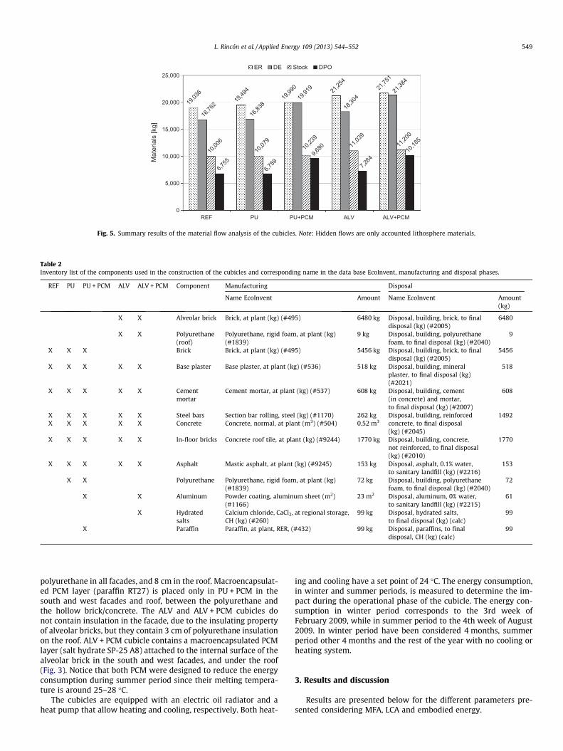
Fig. 5. Summary results of the material flow analysis of the cubicles. Note: Hidden flows are only accounted lithosphere materials.
Table 2Inventory list of the components used in the construction of the cubicles and corresponding name in the data base EcoInvent, manufacturing and disposal phases.
REF PU PU + PCM ALV ALV + PCM Component Manufacturing Disposal
Name EcoInvent Amount Name EcoInvent Amount(kg)
X X Alveolar brick Brick, at plant (kg) (#495) 6480 kg Disposal, building, brick, to finaldisposal (kg) (#2005)
6480
X X Polyurethane(roof)
Polyurethane, rigid foam, at plant (kg)(#1839)
9 kg Disposal, building, polyurethanefoam, to final disposal (kg) (#2040)
9
X X X Brick Brick, at plant (kg) (#495) 5456 kg Disposal, building, brick, to finaldisposal (kg) (#2005)
5456
X X X X X Base plaster Base plaster, at plant (kg) (#536) 518 kg Disposal, building, mineralplaster, to final disposal (kg)(#2021)
518
X X X X X Cementmortar
Cement mortar, at plant (kg) (#537) 608 kg Disposal, building, cement(in concrete) and mortar,to final disposal (kg) (#2007)
608
X X X X X Steel bars Section bar rolling, steel (kg) (#1170) 262 kg Disposal, building, reinforcedconcrete, to final disposal(kg) (#2045)
1492X X X X X Concrete Concrete, normal, at plant (m3) (#504) 0.52 m3
X X X X X In-floor bricks Concrete roof tile, at plant (kg) (#9244) 1770 kg Disposal, building, concrete,not reinforced, to final disposal(kg) (#2010)
1770
X X X X X Asphalt Mastic asphalt, at plant (kg) (#9245) 153 kg Disposal, asphalt, 0.1% water,to sanitary landfill (kg) (#2216)
153
X X Polyurethane Polyurethane, rigid foam, at plant (kg)(#1839)
72 kg Disposal, building, polyurethanefoam, to final disposal (kg) (#2040)
72
X X Aluminum Powder coating, aluminum sheet (m2)(#1166)
23 m2 Disposal, aluminum, 0% water,to sanitary landfill (kg) (#2215)
61
X Hydratedsalts
Calcium chloride, CaCl2, at regional storage,CH (kg) (#260)
99 kg Disposal, hydrated salts,to final disposal (kg) (calc)
99
X Paraffin Paraffin, at plant, RER, (#432) 99 kg Disposal, paraffins, to finaldisposal, CH (kg) (calc)
99
L. Rincón et al. / Applied Energy 109 (2013) 544–552 549
polyurethane in all facades, and 8 cm in the roof. Macroencapsulat-ed PCM layer (paraffin RT27) is placed only in PU + PCM in thesouth and west facades and roof, between the polyurethane andthe hollow brick/concrete. The ALV and ALV + PCM cubicles donot contain insulation in the facade, due to the insulating propertyof alveolar bricks, but they contain 3 cm of polyurethane insulationon the roof. ALV + PCM cubicle contains a macroencapsulated PCMlayer (salt hydrate SP-25 A8) attached to the internal surface of thealveolar brick in the south and west facades, and under the roof(Fig. 3). Notice that both PCM were designed to reduce the energyconsumption during summer period since their melting tempera-ture is around 25–28 �C.
The cubicles are equipped with an electric oil radiator and aheat pump that allow heating and cooling, respectively. Both heat-
ing and cooling have a set point of 24 �C. The energy consumption,in winter and summer periods, is measured to determine the im-pact during the operational phase of the cubicle. The energy con-sumption in winter period corresponds to the 3rd week ofFebruary 2009, while in summer period to the 4th week of August2009. In winter period have been considered 4 months, summerperiod other 4 months and the rest of the year with no cooling orheating system.
3. Results and discussion
Results are presented below for the different parameters pre-sented considering MFA, LCA and embodied energy.

141130152141117
5,0725,1374,9815,028
8,19827272726
28
0
1,000
2,000
3,000
4,000
5,000
6,000
7,000
8,000
9,000
REF PU PU+PCM ALV ALV+PCM
Manufacturing Operational Disposal
-37.7% -38.2% -36.5% -37.2%
Cubicle
EI9
9 [I
mpa
ct p
oint
s]
Fig. 6. EI99 impact points for each phase and comparison to REF cubicle.
550 L. Rincón et al. / Applied Energy 109 (2013) 544–552
3.1. MFA: Total material requirement and ecological rucksack
The material flow model for the REF cubicle is presented inFig. 4, as a representative example. In the REF cubicle, to obtainthe building with 5.76 m2 of net floor area, a TMR of 104,605 kgwas extracted from the environment. Avoiding air and water use,this amount was 35,159 kg. DE meant 16,762 kg. From thisamount, 10,006 kg were finally used to build the cubicle, whilethe rest went back to the environment (DPO) as wastes to pedo-sphere (5761 kg), to atmosphere (987 kg), and to hydrosphere(7 kg). The hidden flows rose up to 87,844 kg, and avoiding airand water, they meant 19,036 kg.
Fig. 5 presents a summary of MFA results for each cubicle. In or-der to make the material requirement more visible, air and waterare not accounted in this graphic. MFA results of the REF cubicleshow that per every kg of stored material, 3.5 kg of materials wereextracted from the environment (kgTMR/kgstock). 1.9 kg of them cor-responded to the hidden flows. In the case of PU and PU + PCMcubicle the ratio kgTMR/kgstock is higher with 3.54 and 3.55 respec-tively, and 1.93 kg and 1.95 kg of hidden flows, respectively. ALVand ALV + PCM have the same ratio kgTMR/kgstock with 3.52. How-ever, there is a small difference between ratios of hidden flowsper stock; for ALV is 1.93 while for ALV + PCM is 1.94. The ecolog-ical rucksack of PCM cubicles is 1% higher than the same cubiclewithout PCM, but it could be even higher since no datum is avail-able for quantifying salt hydrates and paraffin ecological rucksack,as shown in Table 1.
Differences among the outputs of the cubicles were found:about 0.7 kgDPO/kgstock in the REF, PU and ALV, and about 0.9 kgDPO/kgstock in the case of adding macroencapsulated PCM to the con-structive system (PU + PCM and ALV + PCM cubicles). For similarstock among the five cubicles, higher DPO was found when addingPCM. This was due not only to the addition of PCM in but also tothe aluminum macroencapsulation. The substitution of the alumi-num for another material with lower DPO would help to decreasethe overall impact.
Compared to the REF cubicle, all cubicles have higher TMR: forPU it is 2% higher, PU + PCM 3%, ALV 10%, and ALV + PCM 12%.
3.2. LCA: Impact on the environment
The inventory list of the materials used in the manufacturingand disposal phases, and their correlation to the EI99 database isshown in Table 2.
The environmental impacts of the five cubicles are expressedwith the impact points in each phase, and they are summarized
in Fig. 6. The operational phase had the highest impact on the envi-ronment, about 97% of the total in all the cases. Compared to thereference cubicle, there is an improvement in the environmentalimpact between 36.5% and 38.2% for the rest of the cubicles. Theconstructive system with less total impact was the PU + PCMcubicle.
When comparing the same cubicle with and without PCM, theaddition of PCM meant in the manufacturing phase an increaseof the impact points about 8%, and in the disposal phase about0.7%. In contrast, in the operational phase the addition of PCM re-duced the global impact point about 1%.
On the other hand, the addition of polyurethane to the brick fa-cade increased the manufacturing impact points by 21% in compar-ison to the reference, which reflects its high embodied energy.Nevertheless, the effect of this insulating material reduced the glo-bal operational impact by 39%, compared to the reference cubicle,due to the energy savings produced, especially in the winterperiod.
3.3. Embodied energy of the materials and energy consumption of thecubicles
The total energy of the cubicles, considering the embodied en-ergy in manufacturing phase and the energy consumption of heat-ing and cooling during the cubicle lifespan of 80 years, are shownin Table 3. The addition of polyurethane to a cavity wall in PU fa-cade involved a total energy reduction of the cubicle of 35.5% re-spect to REF, even though this facade system has higherembodied energy. In the case of PU + PCM cubicle, the total energyreduction was slightly smaller, with 34.6%. Alveolar brick wall,with a better thermal insulation and thermal mass than REF,achieved similar total energy results with a reduction of 34.9%.
When considering the same cubicle with and without PCM, theaddition of PCM to the facade increased the embodied energy re-spect to the PU cubicle in 25% and of ALV cubicle in 28%. Althoughit reduced the cooling energy consumption by 15% and 17%,respectively, it did not decrease the total energy for a scenario of80 years lifespan.
3.4. Intensities comparison
Material intensity was compared to energy intensity and to im-pact intensity in Table 4. The highest impact intensity was found inthe REF cubicle. The rest of the cubicles with PU and ALV, with andwithout PCM, showed the same order of magnitude of impact

Table 3Embodied energy in manufacturing phase and energy consumption along operational phase of the cubicle lifespan (units: kW h).
Cubicle Manufacturing Operational Total energy Reduction to REF (%)
Embodied energy Cooling energy consumption (80 years) Heating energy consumption (80 years)
REF 6115 11,195 122,536 139,846 –PU 8179 5018 77,004 90,201 �35.5PU + PCM 10,196 4249 77,004 91,449 �34.6ALV 7175 6207 77,599 90,981 �34.9ALV + PCM 9193 5147 77,599 91,939 �34.3
Table 4Material intensity (mass per area) compared to energy intensity (energy per area) and impact intensity (impact points per area).
Cubicle Impact intensity (points/m2) Material intensity (kg/m2) Energy intensity (kWh/m2)
REF 1448 18,161 24,279PU 902 23,924 15,660PU + PCM 896 30,706 15,877ALV 919 20,630 15,795ALV + PCM 910 27,411 15,962
L. Rincón et al. / Applied Energy 109 (2013) 544–552 551
intensity with small differences among them, finding the lowestone in the PU + PCM cubicle.
The lowest material intensity was found in the REF cubicle, fol-lowed by the ALV and PU cubicles. When PCM was added to theconstructive systems, the material intensity increased about7000 kg.
4. Conclusions
In this paper, the environmental impacts of different construc-tive systems of the building envelope have been evaluated bymeans of two complementary methodologies, Material Flow Anal-ysis (MFA) and Life Cycle Assessment (LCA). This paper has shownthat MFA and LCA can be used together to offer a complete evalu-ation of the sustainability of building constructive systems.
The evaluation was done in five cubicles: three with a conven-tional brick facade (without insulation, with polyurethane, andadding PCM to polyurethane), and two built with alveolar brick(with and without PCM).
MFA results revealed that the construction of a conventionalbrick facade implies that per every kg of finally placed constructionmaterial, 3.5 times more materials have been extracted from theenvironment, which is a significant ecological rucksack. 55% ofthe total material requirement (1.9 kg per every kg of final placedconstruction material) corresponded to the hidden flows, whichare materials with no economic value but with environmentalrepercussion that should be considered in environmentalevaluation.
LCA showed that the highest impact was due to the operationalphase (97%). Therefore, the addition of PCM and polyurethane tothe facade with higher impact in manufacturing and disposal phasewas balanced in the operational phase, due to energy savings, con-sidering a building service life of 80 years.
The comparison among the Impact, Material and Energy inten-sities showed that the extraction of the total amount of natural re-sources, which includes the ecological rucksack of the buildingmaterials, is not considered in the LCA. The MFA evidences theneed of accounting this amount of materials in the LCA. Energyintensity is correlated with impact intensity which evidences theconsideration of energy consumption in the LCA.
Acknowledgements
The work was partially funded by the Spanish government(ENE2011-28269-C03-01, ENE2011-28269-C03-02, ENE2011-
28269-C03-03 and ULLE10-4E-1305) and the European Union(COST Action COST TU0802), in collaboration with and the Cityhallof Puigverd de Lleida. The authors would like to thank the CatalanGovernment for the quality accreditation given to their researchgroups SUSCAPE and GREA (2009 SGR 545, 2009 SGR 534). LídiaRincón would like to thank the University of Lleida for her researchfellowship.
References
[1] Krausmann F, Gingrich S, Eisenmenger N, Erb K, Haberl H, Fischer-Kowalski M.Growth in global materials use, GDP and population during the 20th century.Ecol Econ 2009;68:2696–705.
[2] Haapio A, Viitaniemi P. Environmental effect of structural solutions andbuilding materials to a building. Environ Impact Assess 2008;28:587–600.
[3] Rincón L, Pérez G, Castell A, Cuchí A, Cabeza LF. Implementation of the MaterialFlow Analysis methodology on the building sector of a Spanish region. J ConstrEng M ASCE (submitted for publication).
[4] Rincón L, Pérez G, Medrano M, Cabeza L. Material flow analysis in thermalenergy storage. Effstock 2009. In: 11th International conference thermalenergy storage. Energi-och Miljötekniska Föreningen/EMTF Förlag. Stockholm(Sweden), 2009, p. 81.
[5] Rincón L, Pérez G, Cabeza LF. Material Flow Analysis in buildings: a review. JEnviron Manage (submitted for publication).
[6] Rodrigo J, Cañellas N, Meneses M, Castells F, Solé C. El consumo de energía y elmedio ambiente en la vivienda en España. Análisis de Ciclo de Vida (ACV)Energy consumption and environment in spanish dwellings. Life CycleAssessment (LCA). Fundación Gas Natural, Barcelona, 2008.
[7] Zabalza Bribián I, Aranda Usón A, Scarpellini S. Life cycle assessment inbuildings: state-of-the-art and simplified LCA methodology as a complementfor building certification. Build Environ 2009;44:2510–20.
[8] Ortiz O, Pasqualino JC, Díez G, Castells F. The environmental impact of theconstruction phase: an application to composite walls from a life cycleperspective. Resour Conserv Recycl 2010;54:832–40.
[9] Menoufi K, Castell A, Navarro L, Pérez G, Boer D, Cabeza LF. Evaluation of theenvironmental impact of experimental cubicles using Life Cycle Assessment: ahighlight on the manufacturing phase. Appl Energy 2012;92:534–44.
[10] Zheng G, Jing Y, Huang H, Zhang X, Gao Y. Application of Life Cycle Assessment(LCA) and extenics theory for building energy conservation assessment. Energy2009;34:1870–9.
[11] Kellenberger D, Althaus H. Relevance of simplifications in LCA of buildingcomponents. Build Environ 2009;44:818–25.
[12] Gebreslassie BH, Guillén-Gosálbez G, Jiménez L, Boer D. Design ofenvironmentally conscious absorption cooling systems via multi-objectiveoptimization and life cycle assessment. Appl Energy 2009;86:1712–22.
[13] Castellón C, Castell A, Medrano M, Martorell I, Cabeza LF. Experimental studyof PCM inclusion in different building envelopes. J Sol Energy-T ASME2009;131:0410061–66.
[14] Castell A, Martorell I, Medrano M, Pérez G, Cabeza LF. Experimental study ofusing PCM in brick constructive solutions for passive cooling. Energy Build2010;42:534–40.
[15] de Gracia A, Rincón L, Castell A, Jiménez M, Boer D, Medrano M, et al. Life CycleAssessment of the inclusion of phase change materials (PCM) in experimentalbuildings. Energy Build 2010;42:1517–23.
[16] Castell A, Menoufi K, de Gracia A, Rincón L, Boer D, Cabeza LF. Life CycleAssessment of alveolar brick construction system incorporating phase changematerials (PCMs). Appl Energy 2012.

552 L. Rincón et al. / Applied Energy 109 (2013) 544–552
[17] Brunner PH, Rechberger H. Practical handbook of material flow analysis. BocaRaton (FL): CRC/Lewis; 2004.
[18] Commission European. Economy-wide material flow accounts and derivedindicators: a methodological guide. Luxembourg: European Communities;2001.
[19] Wuppertal Institute. Material intensity of materials, fuels, transport andservices. Version 2, 2003.
[20] Ritthoff M, Rohn H, Liedtke C. Calculating MIPS: Resource productivity ofproducts and services. Wuppertal Spezial, Wuppertal Institut für Klima,Umwelt und Energie, 2002.
[21] Rincón L, Pérez G, Cabeza LF. Service life of the dwelling stock in Spain. Int JLife Cycle Ass (in press), http://dx.doi.org/10.1007/s11367-013-0552-x.
[22] Fullana P, Puig R. Análisis del ciclo de vida: Rubes Editorial, 1997.[23] ISO E. ISO 14040: 2006. Environmental management—life cycle assessment—
principles and framework (ISO 14040: 2006). Brussels: CEN (EuropeanCommittee for Standardisation); 2006.
[24] ISO E. ISO 14044: 2006. Environmental management – life cycle assessment –requirements and guidelines. Brussels: CEN (European Committee forStandardisation); 2006.
[25] Consultants PRé. Eco-indicator 99 Manual for designers. Ministry ofhousing, spatial planning and the environment. The Hague, The Netherlands,2000.
[26] Bare JC, Hofstetter P, Pennington DW, Haes U. Life cycle impact assessmentworkshop summary – midpoints versus endpoints: the sacrifices and benefits.Int J Life Cycle Ass 2000;5:319–26.
[27] Goedkoop M, Effting S, Collignon M. The eco-indicator 99. Amersfoot: PRéConsultants B.V; 2000.
[28] Ecoinvent Centre. Ecoinvent, database, 2006.[29] Hegner S. Embodied energy for energy efficiency measures an assessment of
embodied energy‘s relevance for energy saving in the Swiss residentialbuilding sector, 2007.