evaluation of environmentally friendly ag-ptfe...
TRANSCRIPT
Evaluation of environmental friendly Ag-PTFE compositecoating for use in threaded compression fittings
Item type Article
Authors Sieh, Raymond; Le, Huirong
Citation Sieh, R. and Le, H. (2017) 'Evaluation of environmentalfriendly Ag-PTFE composite coating for use in threadedcompression fittings', Proceedings of the Institution ofMechanical Engineers, Part J: Journal of EngineeringTribology, DOI: 10.1177/1350650117719775
DOI 10.1177/1350650117719775
Publisher Sage Publications
Journal Proceedings of the Institution of Mechanical Engineers,Part J: Journal of Engineering Tribology
Rights Archived with thanks to Proceedings of the Institution ofMechanical Engineers, Part J: Journal of EngineeringTribology
Downloaded 3-Jul-2018 20:49:44
Link to item http://hdl.handle.net/10545/621843
Sensitivity: Internal
Evaluation of environmentally friendly Ag-PTFE
composite coating for use in threaded compression
fittings
R. Sieh1, H.R. Le
2
1School of Marine Science and Engineering, University of
Plymouth, United Kingdom 2Department of Engineering, College of Engineering and
Technology, University of Derby, United Kingdom
Abstract
Threaded tubular fittings are used in a wide variety of industries
for critical applications involving fluid transfer in a pressurised or
vacuum system. These fittings are made out of corrosion resistant
metals such as stainless steel which are desirable in corrosive
operating conditions; however, stainless steel is prone to galling
which can cause threads to seize, resulting in loss productivity. To
prevent this, threads are electroplated using silver (Ag) coatings
which prevent galling and serve as a solid lubricant during the
make-up process. The Ag cyanide electroplating process currently
used in industry is both hazardous to human health and its wastes
are detrimental to the environment. The objective of this work is to
evaluate environmentally friendly self-lubricating Ag and Ag-
PTFE coatings using a non-cyanide electroplating process against
the commercially available cyanide Ag coating through the
analysis of torque-angle signatures and the torque-angle slope
which characterises the make-up process. Results from the
experiments suggest that the non-cyanide Ag-PTFE coating is a
potentially viable replacement option. Investigation and analysis of
the coating performance have also highlighted potential risks of
failure through poor lubrication during the make-up process and
suggestions for improving the make-up process.
Sensitivity: Internal
Key Words:
Non-cyanide; silver plating; Ag-PTFE; compression fittings; threaded connections; pulse
electroplating;
Nomenclature
I = Current in Coulombs per second
t = Time in seconds
A = Atomic weight of the metal in grams per mole
n = Valence of the dissolved metal in solution in equivalents per mole
F* = Faraday’s constant (96,485.309 Coulombs/equivalent)
T* = Thickness of deposit in microns
ρ = density in grams per cubic centimetre
S = surface area of the part in square centimetres
T = Torque applied or input torque
F = Force generated during tightening of the nut
C = Constant (friction factor)
P = Thread pitch
µ𝑡ℎ𝑟𝑒𝑎𝑑 = Coefficient of friction in threads
𝑟𝑡 = Effective radius of thread contact
cos 𝛽= 30° for UN/ISO threads
µ𝑏 = Coefficient of friction under head
𝑟𝑛 = Effective radius of nut under-head contact
CoF = Coefficient of friction
Sensitivity: Internal
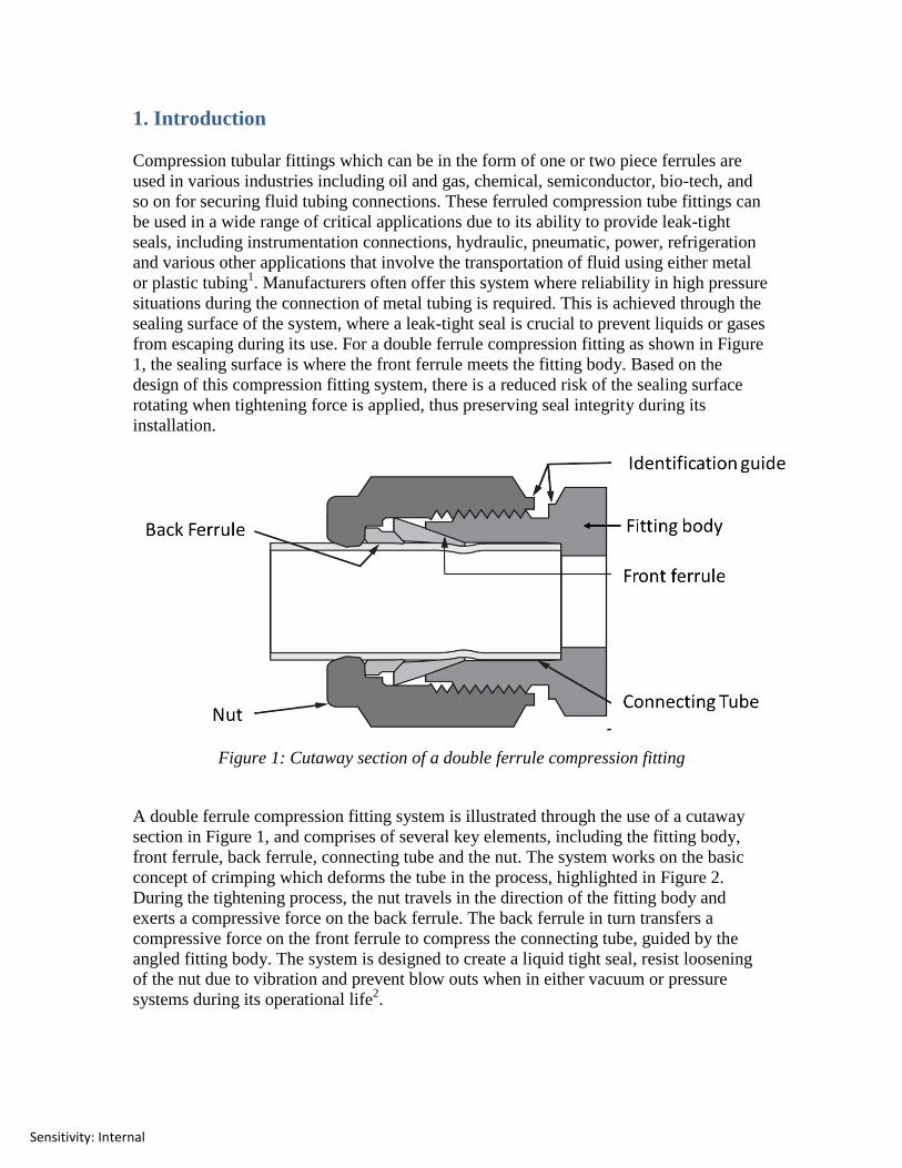
1. Introduction
Compression tubular fittings which can be in the form of one or two piece ferrules are
used in various industries including oil and gas, chemical, semiconductor, bio-tech, and
so on for securing fluid tubing connections. These ferruled compression tube fittings can
be used in a wide range of critical applications due to its ability to provide leak-tight
seals, including instrumentation connections, hydraulic, pneumatic, power, refrigeration
and various other applications that involve the transportation of fluid using either metal
or plastic tubing1. Manufacturers often offer this system where reliability in high pressure
situations during the connection of metal tubing is required. This is achieved through the
sealing surface of the system, where a leak-tight seal is crucial to prevent liquids or gases
from escaping during its use. For a double ferrule compression fitting as shown in Figure
1, the sealing surface is where the front ferrule meets the fitting body. Based on the
design of this compression fitting system, there is a reduced risk of the sealing surface
rotating when tightening force is applied, thus preserving seal integrity during its
installation.
Figure 1: Cutaway section of a double ferrule compression fitting
A double ferrule compression fitting system is illustrated through the use of a cutaway
section in Figure 1, and comprises of several key elements, including the fitting body,
front ferrule, back ferrule, connecting tube and the nut. The system works on the basic
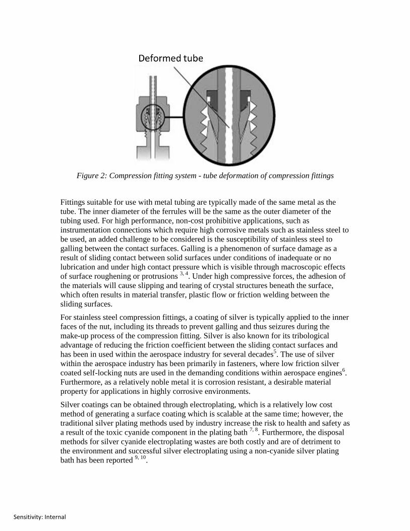
concept of crimping which deforms the tube in the process, highlighted in Figure 2.
During the tightening process, the nut travels in the direction of the fitting body and
exerts a compressive force on the back ferrule. The back ferrule in turn transfers a
compressive force on the front ferrule to compress the connecting tube, guided by the
angled fitting body. The system is designed to create a liquid tight seal, resist loosening
of the nut due to vibration and prevent blow outs when in either vacuum or pressure
systems during its operational life2.
Sensitivity: Internal
Figure 2: Compression fitting system - tube deformation of compression fittings
Fittings suitable for use with metal tubing are typically made of the same metal as the
tube. The inner diameter of the ferrules will be the same as the outer diameter of the
tubing used. For high performance, non-cost prohibitive applications, such as
instrumentation connections which require high corrosive metals such as stainless steel to
be used, an added challenge to be considered is the susceptibility of stainless steel to
galling between the contact surfaces. Galling is a phenomenon of surface damage as a
result of sliding contact between solid surfaces under conditions of inadequate or no
lubrication and under high contact pressure which is visible through macroscopic effects
of surface roughening or protrusions 3, 4
. Under high compressive forces, the adhesion of
the materials will cause slipping and tearing of crystal structures beneath the surface,
which often results in material transfer, plastic flow or friction welding between the
sliding surfaces.
For stainless steel compression fittings, a coating of silver is typically applied to the inner
faces of the nut, including its threads to prevent galling and thus seizures during the
make-up process of the compression fitting. Silver is also known for its tribological
advantage of reducing the friction coefficient between the sliding contact surfaces and
has been in used within the aerospace industry for several decades5. The use of silver
within the aerospace industry has been primarily in fasteners, where low friction silver
coated self-locking nuts are used in the demanding conditions within aerospace engines6.
Furthermore, as a relatively noble metal it is corrosion resistant, a desirable material
property for applications in highly corrosive environments.
Silver coatings can be obtained through electroplating, which is a relatively low cost
method of generating a surface coating which is scalable at the same time; however, the
traditional silver plating methods used by industry increase the risk to health and safety as
a result of the toxic cyanide component in the plating bath 7, 8
. Furthermore, the disposal
methods for silver cyanide electroplating wastes are both costly and are of detriment to
the environment and successful silver electroplating using a non-cyanide silver plating
bath has been reported 9, 10
.
Sensitivity: Internal
Apart from electroplating pure metals such as silver, there has been a relatively new trend
of incorporating other materials such as polymers during the electroplating process to
form a metal matrix composite (MMC)11
. It is possible to improve the tribological
properties of a silver MMC through the addition of the fluoropolymer PTFE which is
already established in its use as a solid lubricant for various applications12
. However,
those familiar with the PTFE polymer are also aware of the issues surrounding its
handling during the incorporation process as it is chemically inert and has a low surface
tension. The issue of surface tension can be overcome through the addition of a suitable
surfactant, which changes the surface tension of PTFE as it is suspended in the
electroplating bath. Surfactants have been used for this and one that has been used
successfully for PTFE is the FC-4 surfactant13
.
The electroplating process is one that can be carried out through several methods, namely
through the use of a direct current method, pulsed current method or a pulsed reverse
current method. The direct current method is carried out by the application of a direct
potential and current in an electroplating bath; on the other hand, pulsed current or pulse
reversed current methods use the rapid alternating of current between different values in a
series of pulses with the amplitude, polarity and duration separated by zero current 14-16
.
Changes in the electroplating methods will result in changes to the microstructure of the
coating. The advantages of pulsed plating over typical direct current plating apart from
improved throwing power is that it is able to generate coatings that are harder with
smaller grain sizes and of low porosity as well as being able to have increased foreign
particle incorporation 17-19
.
There is a tribological benefit of reducing the friction coefficient when incorporating
PTFE particles into the electroplated silver metal matrix composite10
. The issue of
friction in threaded connections is one that has been studied in detail for threaded
fasteners such as bolts and nuts, where the conversion of torque input to the applied
forces within the system is greatly affected by friction 20
. A practical technique for
evaluating and verification of the force achieved for fasteners is the torque-angle curve.
The torque-angle signature method is carried out through the examination of the
tightening and loosening curves during the installation process, through plots of torque
versus angle during its installation and removal21
.
2. Experimental method
The performance of non-cyanide Ag and Ag-PTFE coatings were tested along with the
commercially available cyanide silver coated nuts through a torque experiment. Based on
the assembly instruction for the compression fitting provided by the manufacturer, the
whole compression fitting assembly should be made up and the nut tightened to finger
tight prior to applying torque using a torque wrench. An angle target of 450 degrees is
provided by the manufacturer for making up the specified assembly without any specific
torque specification. To ensure a consistent finger tight value is achieved across the
experiment, all the nuts are pre-tightened to a value of 2Nm. For the reassembly process,
although certain manufacturers state that lubricants may be applied if required, none will
be applied for all the experiments.
Sensitivity: Internal
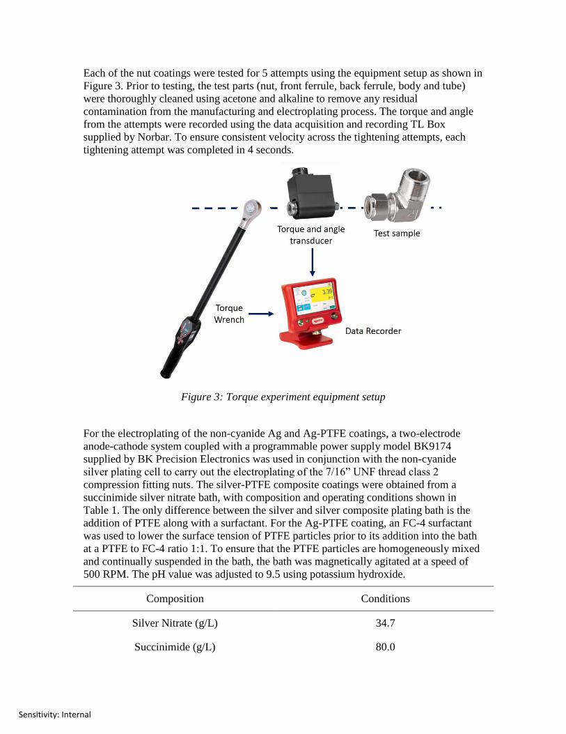
Each of the nut coatings were tested for 5 attempts using the equipment setup as shown in
Figure 3. Prior to testing, the test parts (nut, front ferrule, back ferrule, body and tube)
were thoroughly cleaned using acetone and alkaline to remove any residual
contamination from the manufacturing and electroplating process. The torque and angle
from the attempts were recorded using the data acquisition and recording TL Box
supplied by Norbar. To ensure consistent velocity across the tightening attempts, each
tightening attempt was completed in 4 seconds.
Figure 3: Torque experiment equipment setup
For the electroplating of the non-cyanide Ag and Ag-PTFE coatings, a two-electrode
anode-cathode system coupled with a programmable power supply model BK9174
supplied by BK Precision Electronics was used in conjunction with the non-cyanide
silver plating cell to carry out the electroplating of the 7/16” UNF thread class 2
compression fitting nuts. The silver-PTFE composite coatings were obtained from a
succinimide silver nitrate bath, with composition and operating conditions shown in
Table 1. The only difference between the silver and silver composite plating bath is the
addition of PTFE along with a surfactant. For the Ag-PTFE coating, an FC-4 surfactant
was used to lower the surface tension of PTFE particles prior to its addition into the bath
at a PTFE to FC-4 ratio 1:1. To ensure that the PTFE particles are homogeneously mixed
and continually suspended in the bath, the bath was magnetically agitated at a speed of
500 RPM. The pH value was adjusted to 9.5 using potassium hydroxide.
Composition Conditions
Silver Nitrate (g/L) 34.7
Succinimide (g/L) 80.0
Sensitivity: Internal
Solution pH 9.5
Temperature (°C) 28.0
Table 1. Non-cyanide silver plating electroplating bath composition and parameters
As with any surface finishing operations, sample preparation and pre-treatment prior to
electroplating is a vital part of the process to ensure a repeatable, consistent finishing
quality is achieved for all the nuts summarised in Table 2. Prior to the pre-treatment
process, all the uncoated nut threads were thoroughly cleaned using a non-abrasive nylon
brush to remove any large foreign debris. After a thorough rinse of the nuts using DI
water, the pre-treatment process started off with the immersion of the nuts in a high
purity acetone solution which was then put into an ultrasonic bath for approximately 5
minutes. Another rinse using DI water followed and the nuts were then dried and
immersed in an alkaline cleaning solution containing sodium hydroxide, sodium
carbonate, tribasic sodium phosphate and sodium metasilicate in ultrasonic bath for
further 5 minutes. After a final DI water rinse, the nuts were dried using hot air at
approximately 60°C. After drying, the external surfaces of the nut were masked using a
non-conductive primer which was left to dry in ambient air for a minimum of 24 hours.
After priming and before electroplating, pickling of the cathode surface was carried out
using a 5% hydrochloric acid solution. The electroplating process for Ag-PTFE was
carried out using pulse plating with a frequency set at f = 10Hz and constant current with
a density of 0.2 A/dm2. On the other hand, the pure non-cyanide silver electroplating was
carried out using a constant current method of the same current density. A pure silver
(99.9% purity) acting as the anode was used in both instances. Pulse plating was chosen
for the Ag-PTFE to aid incorporation of the PTFE particles into the MMC, where
coupled with cationic FC-4 surfactant, high PTFE incorporation (in excess of 10 wt.%)
was noted using EDS on test plates.
Procedures Conditions
Acetone cleaning u/s bath 300s at ~20°C
Alkaline cleaning u/s bath 300s at ~20°C
Rinsing Temperature ~20°C
Acid etching, 5% w/v HCL 240s at ~20°C
Rinsing Temperature ~20°C
Ag-PTFE Electroplating 28°C
Rinsing ~20°C
Drying 60°C
Sensitivity: Internal
Table 2. Sample pre-treatment prior to electroplating
3.0 Results, discussion and Analysis
Torque-angle signature curve
Hand torque experiments were carried out based on the setup discussed in the previous
section in an attempt to understand the performance of each coating during the make-up
process. Data was continually recorded across the 450 degree rotation range and used for
further analysis based on the torque-angle signature method. This method is commonly
used to characterise the fastener installation process and can thus be used as a reference
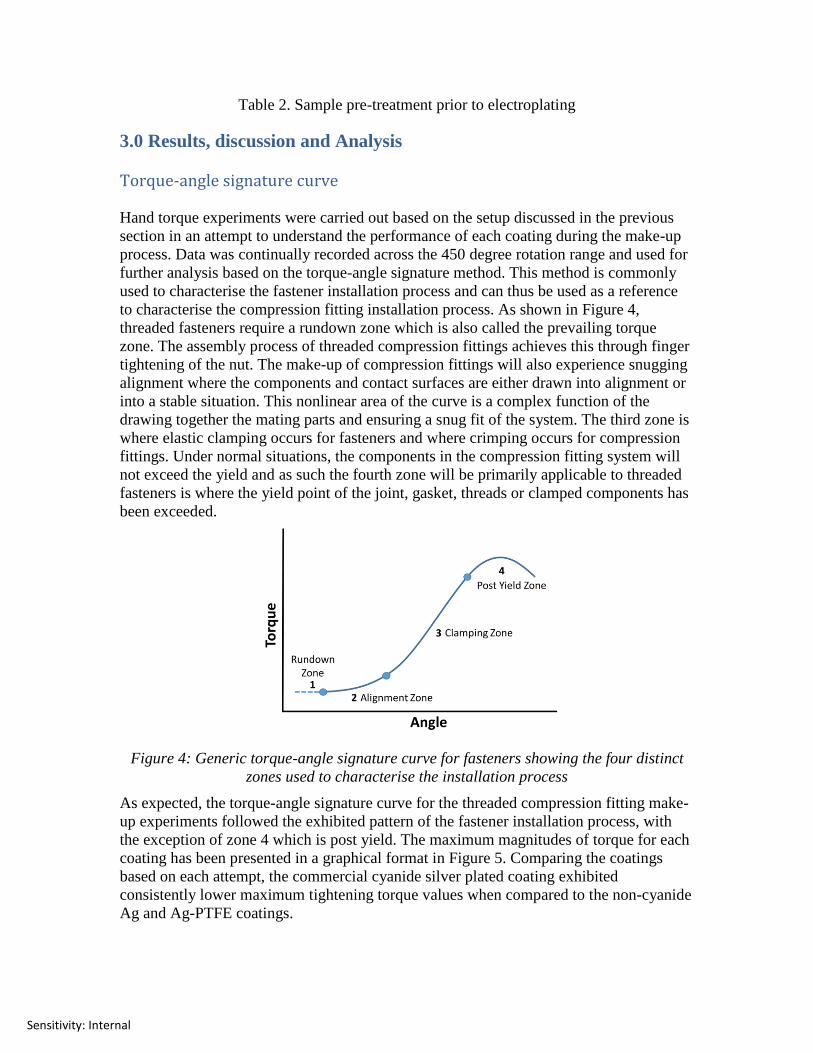
to characterise the compression fitting installation process. As shown in Figure 4,
threaded fasteners require a rundown zone which is also called the prevailing torque
zone. The assembly process of threaded compression fittings achieves this through finger
tightening of the nut. The make-up of compression fittings will also experience snugging
alignment where the components and contact surfaces are either drawn into alignment or
into a stable situation. This nonlinear area of the curve is a complex function of the
drawing together the mating parts and ensuring a snug fit of the system. The third zone is
where elastic clamping occurs for fasteners and where crimping occurs for compression
fittings. Under normal situations, the components in the compression fitting system will
not exceed the yield and as such the fourth zone will be primarily applicable to threaded
fasteners is where the yield point of the joint, gasket, threads or clamped components has
been exceeded.
Figure 4: Generic torque-angle signature curve for fasteners showing the four distinct
zones used to characterise the installation process
As expected, the torque-angle signature curve for the threaded compression fitting make-
up experiments followed the exhibited pattern of the fastener installation process, with
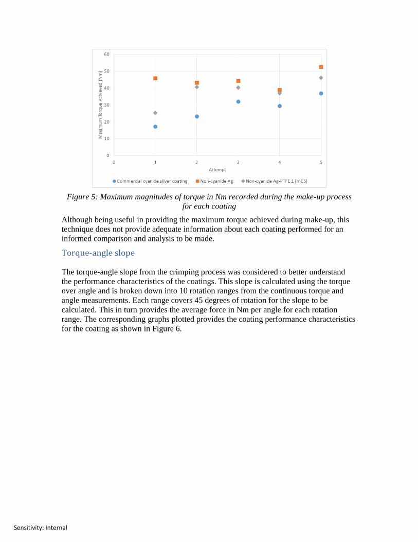
the exception of zone 4 which is post yield. The maximum magnitudes of torque for each
coating has been presented in a graphical format in Figure 5. Comparing the coatings
based on each attempt, the commercial cyanide silver plated coating exhibited
consistently lower maximum tightening torque values when compared to the non-cyanide
Ag and Ag-PTFE coatings.
Sensitivity: Internal
Figure 5: Maximum magnitudes of torque in Nm recorded during the make-up process
for each coating
Although being useful in providing the maximum torque achieved during make-up, this
technique does not provide adequate information about each coating performed for an
informed comparison and analysis to be made.
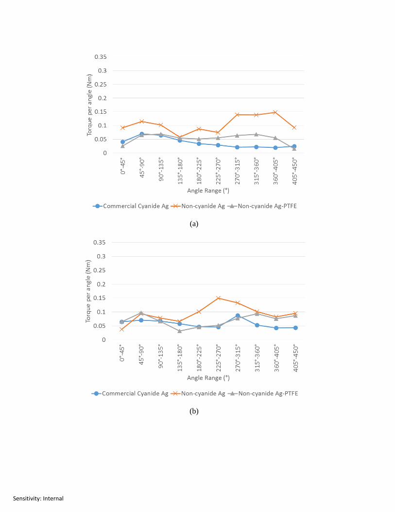
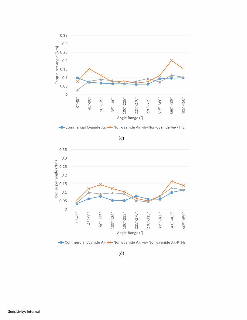
Torque-angle slope
The torque-angle slope from the crimping process was considered to better understand
the performance characteristics of the coatings. This slope is calculated using the torque
over angle and is broken down into 10 rotation ranges from the continuous torque and
angle measurements. Each range covers 45 degrees of rotation for the slope to be
calculated. This in turn provides the average force in Nm per angle for each rotation
range. The corresponding graphs plotted provides the coating performance characteristics
for the coating as shown in Figure 6.
Sensitivity: Internal
(a)
(b)
Sensitivity: Internal
(c)
(d)
Sensitivity: Internal
(e)
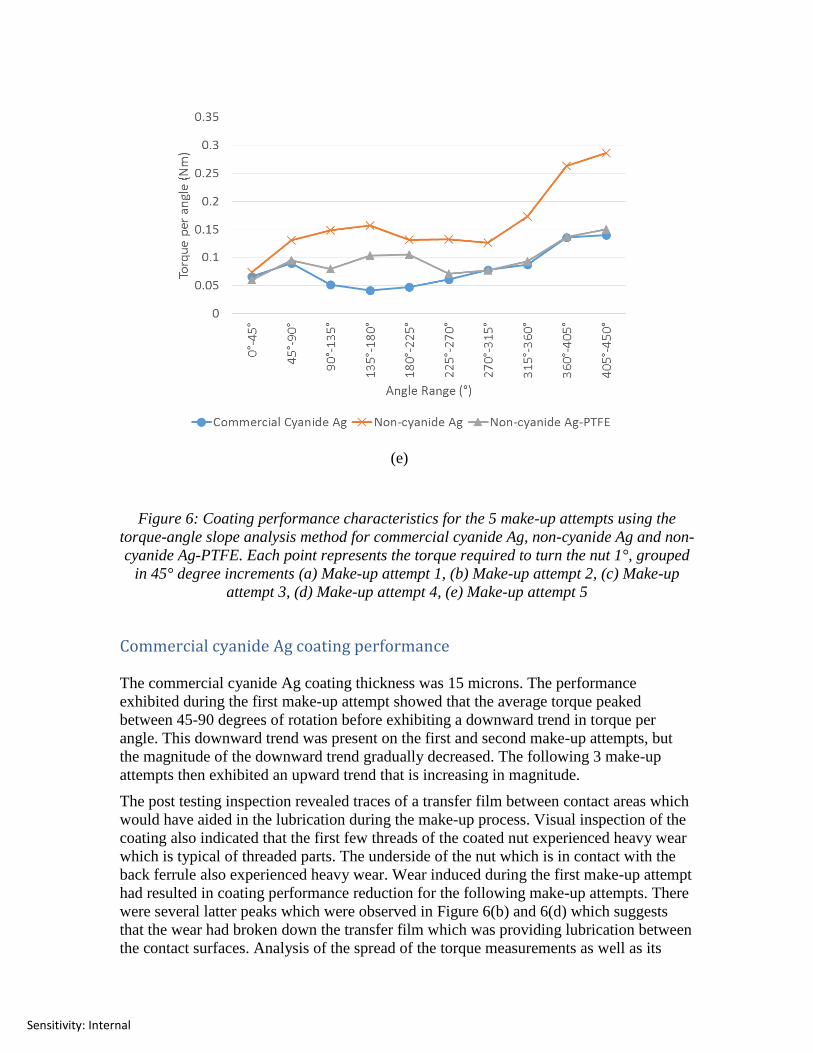
Figure 6: Coating performance characteristics for the 5 make-up attempts using the
torque-angle slope analysis method for commercial cyanide Ag, non-cyanide Ag and non-
cyanide Ag-PTFE. Each point represents the torque required to turn the nut 1°, grouped
in 45° degree increments (a) Make-up attempt 1, (b) Make-up attempt 2, (c) Make-up
attempt 3, (d) Make-up attempt 4, (e) Make-up attempt 5
Commercial cyanide Ag coating performance
The commercial cyanide Ag coating thickness was 15 microns. The performance
exhibited during the first make-up attempt showed that the average torque peaked
between 45-90 degrees of rotation before exhibiting a downward trend in torque per
angle. This downward trend was present on the first and second make-up attempts, but
the magnitude of the downward trend gradually decreased. The following 3 make-up
attempts then exhibited an upward trend that is increasing in magnitude.
The post testing inspection revealed traces of a transfer film between contact areas which
would have aided in the lubrication during the make-up process. Visual inspection of the
coating also indicated that the first few threads of the coated nut experienced heavy wear
which is typical of threaded parts. The underside of the nut which is in contact with the
back ferrule also experienced heavy wear. Wear induced during the first make-up attempt
had resulted in coating performance reduction for the following make-up attempts. There
were several latter peaks which were observed in Figure 6(b) and 6(d) which suggests
that the wear had broken down the transfer film which was providing lubrication between
the contact surfaces. Analysis of the spread of the torque measurements as well as its
Sensitivity: Internal
distribution suggests the increase in wear of the coating under the high operational
stresses which have resulting in its impairment in providing adequate solid lubrication
after consequent make-up processes; however, it had still managed to maintain a
relatively stable performance.
Non-cyanide Ag coating performance
This study is focused towards the performance of the non-cyanide Ag-PTFE coating
compared against the current commercial silver cyanide coating, and an assumption was
made that a thinner non-cyanide Ag-PTFE coating could have equivalent performance
when compared with a thicker commercial silver cyanide coating. The non-cyanide pure
Ag coating in this instance serves as a control and was deposited using similar parameters
to that of the non-cyanide Ag-PTFE coating.
The theoretical coating thickness based on the electroplating parameters for the non-
cyanide Ag coating was 3.83 microns, whereas measured thickness placed this at
approximately 3.3 microns. Theoretical coating thickness calculations in microns were
based on Faraday’s law of electrolysis:
𝑇∗ = 𝐼∗𝑡∗𝐴∗10,000
𝑛∗𝐹∗∗𝜌∗𝑆 --- Eq (1)
Current efficiencies for direct current electroplating are typically around 90%; however,
electroplating a complex geometry will result in uneven deposit thicknesses due to
uneven current distribution. In terms of the torque-angle slope, a consistent higher overall
slope average suggests higher friction is inherent in the system. Although post testing
visual inspection revealed traces of transfer film on the contact surfaces, it was less
apparent as opposed to the commercial cyanide Ag coating. Examination of the
maximum torque values achieved during each make-up process reveals that the coating
had consistently achieved the highest torque. This is further supported by the torque-
angle slope analysis, where the non-cyanide Ag coating required the highest average
torque per angle to make-up. Furthermore, the coating had behaved erratically and
relatively unpredictably during make-up. In relative terms, this is a clear indication of
poor coating wear characteristics which can be attributed to a thinner overall coating.
Non-cyanide Ag-PTFE coating performance
The non-cyanide Ag-PTFE coating managed to exhibit a more consistent performance
over its non-cyanide Ag counterpart; however, its performance was still generally below
that of the commercial cyanide Ag coating. Based on the maximum torque observed
during the make-up process, the non-cyanide Ag-PTFE coating required on average
approximately 8Nm more input torque. One major factor could be the coating thickness
achieved for the current coating. A theoretical thickness of 2.3 microns was calculated
based on a typical pulse plating current efficiency value of 60%. The maximum measured
thickness was 2.1 microns in this instance. Post make-up visual inspection showed
moderate amounts of transfer film residue in relation to the other coatings considered. It
is believed that the PTFE embedded in electroplated silver contributes to providing a
more stable friction and overall increased tribological performance of the coating.
Sensitivity: Internal
Excess torque and wear
An assumption can be made that approximately 17Nm of tightening torque is sufficient
for successful make-up of the system based on ideal conditions. This value represents the
lowest torque value from the cyanide silver coating after a 450 degree cycle of rotation.
However, significantly higher readings of maximum torque in the torque-angle curve
were registered for all the coatings tested during the make-up attempts which require an
adequate explanation as to where this excess torque has gone in the system. Furthermore,
a lot of work has gone into the study of the relationship between input torque and applied
force for threaded fasteners (nut and bolt) which is potentially transferrable to explain
this during the study of threaded compression fittings. The relationship can be expressed
through the short form equation as:
𝑇 = 𝐹 ∗ 𝐶 --- Eq (2)
Although the constant “C” is an experimentally determined factor and is subject to
variations, the straight line relationship between torque applied and force achieved will
always be assumed to be accurate22
. The application of this relationship requires the long
form equation, where there are 3 forms of long form equations that are generally used
which yield the same results. These include the ISO 16047 equation which has been
attributed to Kellerman and Klein, DIN946/VDI2230 equation and Motosh’s equation23
.
Motosh’s equation below is in a format that is easiest to understand, with constituent
terms that make up the equation for the constant, namely thread pitch incline plane,
thread friction and nut under-head friction resistance.
𝑇 = 𝐹 (𝑃
2𝜋+
µ𝑡ℎ𝑟𝑒𝑎𝑑𝑟𝑡
cos 𝛽+ µ𝑏𝑟𝑛) --- Eq (3)
Assuming that Motosh’s equation is valid for threaded compression fittings as the
considerations are the same, it can be rearranged to consider a global CoF value as
follows:
µ𝑔𝑙𝑜𝑏𝑎𝑙 = cos 𝛽 (
𝑇𝑖𝑛𝑝𝑢𝑡
𝐹𝑜𝑝𝑝𝑜𝑠𝑖𝑛𝑔−
𝑃
2𝜋)
𝑟𝑡+𝑟𝑛 cos 𝛽 ----- Eq (4)
The global CoF in Eq (4) then is directly affected by the input torque and instead of the
force generated during tightening for fasteners, the opposing force should be considered.
This opposing force component is comprised of the material resistance from the crimping
process. An increase in the input torque directly results in the proportionate increase in
global CoF. This only explains what is actually happening in an ideal situation though,
where issues such as coating wear are not taken into consideration. The global CoF is
therefore useful as a simplified equation of understanding the theoretical friction within
the system during initial design. The actual application of this during the make-up
process is challenging as there are first and foremost inherent variations in the component
or assembly which is further compounded by the changes in contact pressures during
coating wear.
Sensitivity: Internal
(a)
(b)
(c)
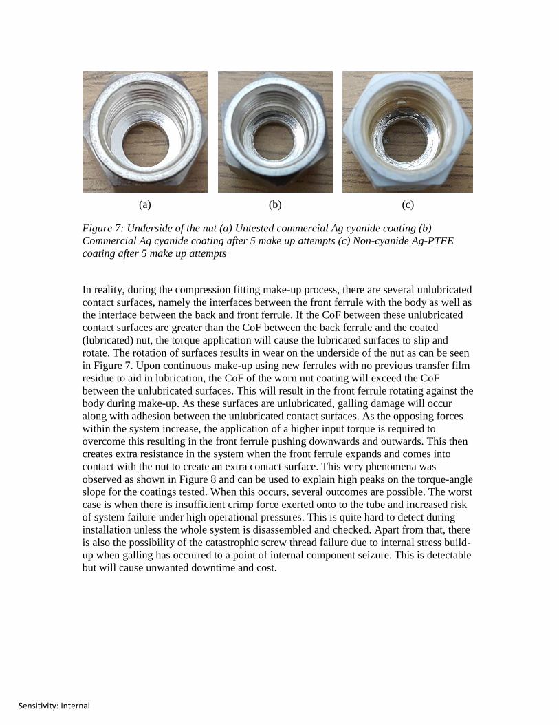
Figure 7: Underside of the nut (a) Untested commercial Ag cyanide coating (b)
Commercial Ag cyanide coating after 5 make up attempts (c) Non-cyanide Ag-PTFE
coating after 5 make up attempts
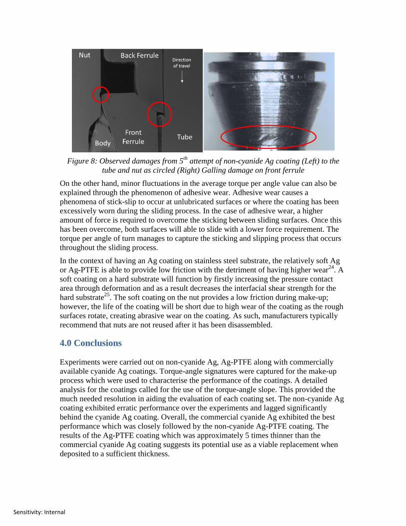
In reality, during the compression fitting make-up process, there are several unlubricated
contact surfaces, namely the interfaces between the front ferrule with the body as well as
the interface between the back and front ferrule. If the CoF between these unlubricated
contact surfaces are greater than the CoF between the back ferrule and the coated
(lubricated) nut, the torque application will cause the lubricated surfaces to slip and
rotate. The rotation of surfaces results in wear on the underside of the nut as can be seen
in Figure 7. Upon continuous make-up using new ferrules with no previous transfer film
residue to aid in lubrication, the CoF of the worn nut coating will exceed the CoF
between the unlubricated surfaces. This will result in the front ferrule rotating against the
body during make-up. As these surfaces are unlubricated, galling damage will occur
along with adhesion between the unlubricated contact surfaces. As the opposing forces
within the system increase, the application of a higher input torque is required to
overcome this resulting in the front ferrule pushing downwards and outwards. This then
creates extra resistance in the system when the front ferrule expands and comes into
contact with the nut to create an extra contact surface. This very phenomena was
observed as shown in Figure 8 and can be used to explain high peaks on the torque-angle
slope for the coatings tested. When this occurs, several outcomes are possible. The worst
case is when there is insufficient crimp force exerted onto to the tube and increased risk
of system failure under high operational pressures. This is quite hard to detect during
installation unless the whole system is disassembled and checked. Apart from that, there
is also the possibility of the catastrophic screw thread failure due to internal stress build-
up when galling has occurred to a point of internal component seizure. This is detectable
but will cause unwanted downtime and cost.
Sensitivity: Internal
Figure 8: Observed damages from 5th
attempt of non-cyanide Ag coating (Left) to the
tube and nut as circled (Right) Galling damage on front ferrule
On the other hand, minor fluctuations in the average torque per angle value can also be
explained through the phenomenon of adhesive wear. Adhesive wear causes a
phenomena of stick-slip to occur at unlubricated surfaces or where the coating has been
excessively worn during the sliding process. In the case of adhesive wear, a higher
amount of force is required to overcome the sticking between sliding surfaces. Once this
has been overcome, both surfaces will able to slide with a lower force requirement. The
torque per angle of turn manages to capture the sticking and slipping process that occurs
throughout the sliding process.
In the context of having an Ag coating on stainless steel substrate, the relatively soft Ag
or Ag-PTFE is able to provide low friction with the detriment of having higher wear24
. A
soft coating on a hard substrate will function by firstly increasing the pressure contact
area through deformation and as a result decreases the interfacial shear strength for the
hard substrate25
. The soft coating on the nut provides a low friction during make-up;
however, the life of the coating will be short due to high wear of the coating as the rough
surfaces rotate, creating abrasive wear on the coating. As such, manufacturers typically
recommend that nuts are not reused after it has been disassembled.
4.0 Conclusions
Experiments were carried out on non-cyanide Ag, Ag-PTFE along with commercially
available cyanide Ag coatings. Torque-angle signatures were captured for the make-up
process which were used to characterise the performance of the coatings. A detailed
analysis for the coatings called for the use of the torque-angle slope. This provided the
much needed resolution in aiding the evaluation of each coating set. The non-cyanide Ag
coating exhibited erratic performance over the experiments and lagged significantly
behind the cyanide Ag coating. Overall, the commercial cyanide Ag exhibited the best
performance which was closely followed by the non-cyanide Ag-PTFE coating. The
results of the Ag-PTFE coating which was approximately 5 times thinner than the
commercial cyanide Ag coating suggests its potential use as a viable replacement when
deposited to a sufficient thickness.
Sensitivity: Internal
Prior to and during the course of the experiments, several key observations were made in
relation to the make-up instructions provided by manufacturers. Firstly, the finger
tightening operation stipulated is a variable, where different installers will exert different
forces onto this. Secondly, the make-up process is only given an angle target. Inadequate
lubrication can result in a large proportion of applied torque subjected to losses within the
system and not on the crimping process. The dissection of the parts after the experiments
highlighted the fact that inadequate lubrication can result in irreversible damage to the
system. It is recommended that the make-up of the compression fittings be to both a
torque and angle specification, especially for critical applications where component
damage is not an option.
Potential future work in relation to this could include the use of servo motors in applying
torque at a consistent velocity from an experimental point of view and also testing
equivalent electroplated thickness coatings over a larger number of make-up attempts.
Acknowledgements
The authors would like to acknowledge Terry Richards and Zoltan Gombos for technical
assistance provided and to Dr A. Cree for constructive discussions during the course. An
award of Postgraduate International Mobility Grant for R.S. from Santander Inc is
gratefully acknowledged.
References
1. Parker Hannifin. Comression Instrumentation Tube Fittings. 2015.
2. Brennan Industries. Double and Single-Ferrule Instrumentation Tube Fittings.
Instrumentation Fittings Catalogue. 2013.
3. ASTM International. Standard Test Method for Galling Resistance of Materials
G98-02. West Conshohocken, PA, USA2009, p. 4.
4. Xie Y and Yao M. Measurement of the threshold galling stress of hardfacing
alloys. Wear. 2003; 255: 509-16.
5. Barrett. R. Nasa Reference Publication 1228: Fastener Design Material. 1990.
6. Tronci G and Marshall MB. Understanding the behaviour of silver as a low
friction coating in aerospace fasteners. Tribology International. 2016; 100: 162-70.
7. Blair A. Silver plating. Metal Finishing. 2001; 99, Supple: 298-304.
8. Jayakrishnan S, Natarajan SR and Vasu KI. Alkaline noncyanide bath for
electrodeposition of silver. Metal Finishing. 1996; 94: 12-5.
9. Boden PJ. Disposal of toxic wastes—1. Electroplating and electrochemical
machining wastes. Conservation & Recycling. 1976; 1: 111-8.
10. Sieh R, Le HR and Cree AM. Process optimisation of non-cyanide Ag–PTFE
metal matrix composite electroplating for threaded connections. Transactions of the IMF.
2015; 93: 232-40.
11. Walsh FC and Ponce de Leon C. A review of the electrodeposition of metal
matrix composite coatings by inclusion of particles in a metal layer: an established and
diversifying technology. Transactions of the IMF. 2014; 92: 83-98.
12. Beckford S, Wang YA and Zou M. Wear-Resistant PTFE/SiO2 Nanoparticle
Composite Films. Tribology Transactions. 2011; 54: 849-58.
Sensitivity: Internal
13. Zhao Q, Liu Y and Wang C. Development and evaluation of electroless Ag-PTFE
composite coatings with anti-microbial and anti-corrosion properties. Applied Surface
Science. 2005; 252: 1620-7.
14. Yin K-M, Jan S-L and Lee C-C. Current pulse with reverse plating of nickel-iron
alloys in a sulphate bath. Surface and Coatings Technology. 1997; 88: 219-25.
15. Marlot A, Kern P and Landolt D. Pulse plating of Ni–Mo alloys from Ni-rich
electrolytes. Electrochimica Acta. 2002; 48: 29-36.
16. Ghaemi M. Effects of direct and pulse current on electrodeposition of manganese
dioxide. Journal of Power Sources. 2002; 111: 248-54.
17. Mentone PF. Pulse vs. DC plating. Metal Finishing. 2005; 103: 14-8.
18. Thiemig D, Lange R and Bund A. Influence of pulse plating parameters on the
electrocodeposition of matrix metal nanocomposites. Electrochimica Acta. 2007; 52:
7362-71.
19. Pearson T and Dennis JK. Facts and fiction about pulse plating. Transactions of
the Institute of Metal Finishing. 1991; 69: 75-9.
20. Eccles W, Sherrington I and Arnell RD. Frictional changes during repeated
tightening of zinc plated threaded fasteners. Tribology International. 2010; 43: 700-7.
21. Shoberg R. Engineering Fundamentals of Threaded Fastener Design and
Analysis.
22. Bickford J. Handbook of Bolts and Bolted Joints. 1998.
23. BSEN ISO. ISO 16047: 2005(E). Fasteners – torque/clamp force testing. Geneva,
Switzerland: International Organization for Standardization, 2005.
24. Holmberg K, Ronkainen H and Matthews A. Tribology of Thin Coatings.
Ceramics International. 2000; 26: 787-95.
25. Jiang H, Browning R, Whitcomb D. J, et al. Mechanical Modeling of Scratch
Behavior of Polymeric Coatings on Hard and Soft Substrates. Tribology Letters. 2010;
37: 159-67.