evaluation of critical resolved shear stress for systems with general periodic stress fields
TRANSCRIPT
M. KATO et al.: Evaluation of Critical Resolved Shear Stress 209
phys. stat. sol. (a) 98, 209 (1986)
Subject classification: 62.20
Department of Materials Science and Engineering, Tokyo Institute of Technology, Yokohama1) (a ) and Depurtment of Metallurgy and Mining ERgineering, University of Illinois at Urbana-Champaign2) (b)
Evaluation of Critical Resolved Shear Stress for Systems with General Periodic Stress Fields
BY M. KATO (a), S. HOEIE (a), and ‘rONG CIIANG L m (b)
Critical resolved shear stress under the absence of thermal activation for systems with general periodic stress fields is discussed. The integration of a dislocation force-balance equation along a stable periodic dislocation reveals that the applied stress always balances with the average of the internal stress and, thus, the critical resolved shear stress is identified as the maximum possible average of the internal stress. The analysis becomes extremely simple if the dislocation is nearly straight.
Es wird die kritische Schubspannung bei Abwesenheit thermischer Aktivierung fur Systeme mit allgemeinen periodischen Spannungsfeldern diskutiert. Die Integration einer Versetzungskraft- gleichgewichtsgleichung entlang einer stabilen periodischen Versetzung zeigt, daB die angelegte Spannung sich immer mit dem Mittelwert der inneren Spannung ausgleicht und somit die kritische Schubspannung als der maximal mogliche Mittelwert der inneren Spannung identifiziert wird. Die Analyse wird extrem einfach, wenn die Versetzung niiherungsweise gerade ist.
1. Introduction
The motion of a dislocation in a periodic internal stress field has been discussed to understand the mechanical properties of b.c.c. metals [l to 61 and spinodal alloys [7 to 131. When the variation of the periodic internal stress is approximated as sinusoi- dal, it is known that the critical resolved shear stress (CRSS) under the absence of thermal activation is equal to the maximum internal stress (e.g., a Peierls stress) for the case of a one-dimensional periodic field [l to 61 and that it is almost exactly equal to one-half of the maximum internal stress for the case of a two-dimensional periodic field such as that in spinodal alloys [8 to 11,131. However, no clear explanation has been developed so far to discuss the physical origin of such a difference in CRSS with respect to the dimensionality of the periodic stress field. Moreover, i t is not yet clear whether such a simple relationship between CRSS and the maximum internal stress exists when the variation profile of a periodic internal stress is not sinusoidal.
The purpose of the present research is to offer a simple method to evaluate CR9S for systems with general periodic internal stress fields with the aid of a dislocation force- balance equation. As will be seen later, the present analysis is particularly useful for systems where the stable dislocation shape in a periodic stress field is regarded as nearly straight.
l) 4259 Nagatsuta, Midori-ku, Yokohama 227, Japan. 2, 1304 West Green Street, Urbana, Illinois 61801, USA.
14 physica (a) 9Sjl
2 10 M. KATO, S. HORIE, and T . ~ N G CHANC LEE
2. Analysis The well-known force-balance equation of a dislocation lying on an x-y slip plane with a shape y = y(x) is written using the string model as
d2y/dx2 ’ {l + ( d y / d ~ ) ~ } ~ ’ ~ + G~(x, y) b - Gab = 0 ,
where y is the line tension of the dislocation, oi(x, y) and G , are respectively the internal stress and applied stress and b is the magnitude of the Burgers vector. In this study, q(~, y) is considered to be a periodic function with respect to 5 and y znd its maximum value is designated as G , ~ . In the absence of thermal activation, a stable shape of a dis- location, obtained as a solution of (l), should also be periodic with respect to x 2nd y with the same wavelength of periodicity as the periodic internal stress [7 to 9,131. Thus, if we cannot obtain a periodic solution for the dislocation shape above 2 certain critical value of the applied stress for any choice of initial conditions to solve ( I ) , the critical value is identified as CRSS, G~ 17 to 9, 131.
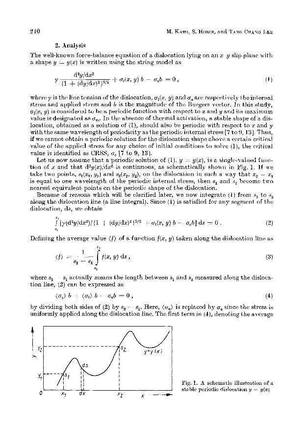
Let us now assume that a periodic solution of (l), y = y(x), is a single-valued func- tion of x and that d2y(x)/dx2 is continuous, as schematically shown in Pig. 1. If we take two points, sl(xl, yl) and s2{x2, y2), on the dislocation in such a way that xg - x1 is equal t o one wavelength of the periodic internal stress, then s1 and s2 become two nearest equivalent points on the periodic shape of the dislocation.
Because of reasons which will be clarified later, we now integrate (1) from s1 to s2 along the dislocation line (a line integral). Since (1) is satisfied for any segment of the dislocation, ds, we obtain
S s
A 1
J [y(d22//dxz)/{l + (d~/dx)’}’/~ + G~(x, y) b - ~ , h ] ds = 0 . (2)
Defining the average value ( f ) of a function f(x, y) taken along the dislocation line as
81
where s2 - s1 actually means the length between sl and s2 measured along the disloca- tion line, (2) can be expressed as
(us) b f ( ~ i ) b - Gab = 0 , (4) by dividing both sides of (2) by s2 - sl. Here, (6,) is replaced by ca since the stress is uniformly applied along the dislocation line. The first term in (4), denoting the average
Wig. 1. A schematic illustration of a stable periodic dislocation y = y(s)
Critical Resolved Shear Stress for Systems with Periodic Stress Fields 211
self force of the dislocation, can be rewritten from (2) by noting ds = {I + + (dy/dz)2}1/2 dz as
5"
{arctan (dy/dx)at2-T2 - arctan (dy/dz)at x = x , } . (5 )
For the periodic shape of the dislocation considered here, (dy/dz),t x=x,aiid(dy/dz)at x=xl are the same and, thus, (a,) b becomes zero. Therefore, (4) reduces to a simple equation
0, = ( q ) . (6)
- - s2 - 81
Since CRSS, oc, is identified as the maximum possible value of ua to have a periodic dislocation shape [7 to 9, 131; we obtain
~c = ( 0 i ) m a x , ( 7 ) where ( c T ~ ) ~ ~ ~ is the maximum possible average value of the internal stress. It should be noted that no approximation whatsoever is involved to derive (7) from (1). Therefore, as long as the periodic dislocation shape is treated, ( 7 ) is rigorously valid.
3. Evaluation of CBSS 3.1 Method
From ( 7 ) , we find that in order to obtain CRSS, we must first know, by solving (l), the periodic shape of a dislocation to give the maximum average value of the internal stress. It should be noted here that there exist in general an infinite number of periodic solutions of the dislocation shape in ( I ) , dcpending on the choice of initial conditions. Therefore, we must choose a specific periodic solution along which the average internal stress becomes maximum. To demonstrate this situation, we express, as an example, the second term in (1) as
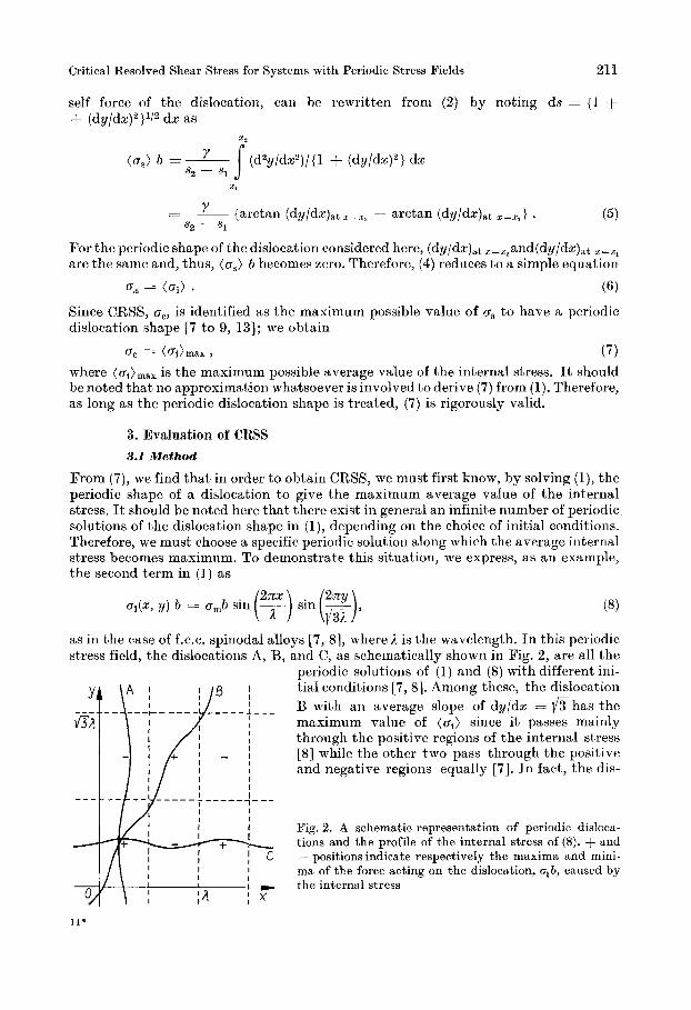
ai(z, y) 6 = amb sin r) __ sin rg), as in the case of f.c.c. spinodal alloys [ 7 , 81, where i is the wavelength. In this periodic stress field, the dislocations A, B, and C, as schematically shown in Fig. 2, are all the
periodic solutions of (1) and (8) with different ini- tial conditions [7 , 81. Among these, the dislocation B with an average slope of dy/dz = li/3has the maximum value of (gi) since it passes mainly through the positive regions of the internal stress [S] while the other two pass through the positive and negative regions equally [7]. In fact, the dis-
Pig. 2. A schematic representation of periodic disloca- tions and the profile of the internal stress of (8). + and - positions indicate respectively the maxima and mini- ma of the force acting on the dislocation, q b, caused by the internal stress
14'
212 M. KATO, S. HORIE, a.nd TANG CHANC LEE
location B is known to have the minimum energy (most stable) and it suffers the largest resistance against its motion [8, 91. In other words, the dislocation B is considered to be responsible for macroscopic yielding and CRSS is determined by thc motion of this specific dislocation [8].
It is in general inevitable to numerically solve (1) to obtain first the dislocation shape and then ( G ~ ) , ~ , ~ ~ . However, an approximate value of (q)max can be found very easily if the curvature of the dislocation is small (a nearly straight dislocation). A criterion for the nearly straight dislocation is described as [8]
a '61 L < 1 . 2 z y (9)
This criterion is known to be satisfied for the stress fields in most spinodal alloys (a,b1/2ny - [ l to 61. In such cases, (ai) is approximately obtained by integrating ai(x, y) along a straight line taken parallel t o and in the middle of the nearly straight dislocation. Then, CRSS is evaluated from (7 ) when a specific straight line is chosen so as to maxi- mize (ai).
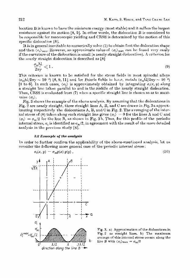
Fig. 3 shows the example of the above analysis. By assuming that the dislocations in Fig. 2 are nearly straight, three straight lines A, B, and C are drawn in Fig. 3 a approx- imating respectively the dislocations A, B, and C in Fig. 2 . The averaging of the inter- nal stress of (8) taken along each straight line gives (ai) = 0 for the lines A and C and (ai) = 0,/2 for the line B, as shown in Fig. 3b. Thus, for this profile of the periodic internal stress, ac is identified as am/2, in agreement with the result of the more detailed analysis in the previous study [8].
[S, 9, 111 and for Peierls fields in b.c.c. metals (omb1/2ny -
3.2 Example of the analysis
In order to further confirm the applicability of the above-mentioned analysis, let us corisider the following more general case of the periodic internal stress:
U i ( G Y) == Orng(x) Y(Y) 7 (10)
I I I I
I I I I I I I I I I - a
O/ I ; A ; 2
Fig. 3. a) Approximation of the dislocations in Fig. 2 as straight lines. b) The maximum average of this internal stress occurs along the line B with <ci)max = cm/2 b
direction dong the line 8-
Critical Resolved Shear Stress for Systems with Periodic Stress Fields
% b
--.. t L..
0 -
-1
213
I I I
I I I I I
- I -
I
-- I I - I I j I I
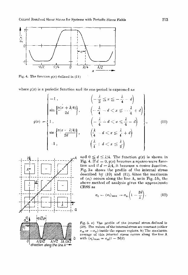
- - Pig. 4. The function g(z) defined in (I 1)
where g(z) is a periodic function and its one period is expressed as
I direction along the [ine A -
and 0 5 d (= 114. The function g ( x ) is shown in Fig. 4. If d = 0, g(x) becomes a square-wave func- tion aiid if d = 214, i t becomes a cosine function. Fig. 5 a shows the profile of the internal stress described by (10) and (11). Since the maximum of (ai) occurs along the line A, as in Fig. 5 b, the above method of aiialysis gives the approximate CRSS as
Fig. 5. a ) The profile of the internal stress defined in (10). The values of the internal stress are constant (either 6, or -cr,,,) inside the square regions. b) The maximum average of this internal stress occurs along the line A with <cri),,, = cr,(l - 2d/A)

214 M. KATO et a].: Evaluation of Critical Resolved Shear Stress
To investigate the accuracy of (12), numerical calculations on a computer were con- ducted using (l), (lo), and (11) with constants y = 5.0 x N, unl = 10s Pa, b = 2.5 x m. The method of calculation was the same as that in the previous study IS]. The results show that the maximum values of the applied stress to obtain a periodic shape of a dislocation are 8.0 x lo7 Pa for d = m and 5.0 x 10' Pa for d = 2.5 x m. These values are the same as those obtained from (12), indicating the validity of this method of analysis.
Such an excellent agreement between the present simple analysis arid the numerical calculation is naturally realized since the chosen numerical constants satisfy criterion (9) (u,,bA/2ny - 8 x in this case). If this criterion is no more satisfied, the present simple method for a nearly straight dislocation may riot result in a good approxirnation. Such a case was numerically treated by a recent work by Mayo [13], keeping in mind the hardening associated withjtlie later stages of the spinodal decomposition. Even in this case ,however, ( 7 ) is still valid. Therefore, CRSS can be obtained from ( 7 ) by taking the average value of the internal stress along a dislocation line.
m, and I =
References
[l] V. CELLI, &I. KABLER, T. NINOMIYA, and R. THOMPSON, Phys. Rev. 131, 58 (19G3). [2] J. E. DORN and S. RAJNAK, Trans. MS AIME 230, 1052 (1964). [3] R. J. ARSENAULT, Acta metall. 15, 501 (1967). [4] 5. SCHLIPH, Phil. Mag. A40, 1 (1979). [ 5 ] T. MORI and &!I. KATO, Phil. Pag. A43, 1315 (1981). [GI M. KATO, phys. stat. sol. (a) 7'3, 517 (1983). 171 J. W. CAHN, Acta metall. 11, 1275 (1963). [8] M. KATO, T. MORI, and L. H. SCHWARTZ, Acta metall. 28, 285 (1980). [91 M. KATO, T. MORI, and L. H. SCHWARTZ, Mater. Sci. Engng. 51, 25 (1981). 101 M. KATO, T. C. LEE, and S. L. CHAN, Mater. Sci. Engng. 54, 145 (1982). 111 T. C. LEE, M. KATO, and T. MORI, Mater. Sci. Engng. 6B, 173 (1984). 121 A. J. ARDELL, Metallurg. Trans. (Phys. Metallurgy and Mater. Sci.) 16A, 2131 (1985). 131 W. E. MAYO, Mater. Sci. Engng. 77, 27 (1986).
(Received July 10, 19S6)