european technical standard order - easa · european technical standard order subject: ... the...
TRANSCRIPT
ED Decision 2016/013/R Annex II
ETSO-C151c
Page 101 of 160
Date: 5.8.2016
European Aviation Safety Agency
European Technical Standard Order
Subject: Terrain Awareness and Warning System (TAWS)
1 — Applicability This ETSO provides the requirements which Terrain Awareness and Warning System (TAWS) that are
designed and manufactured on or after the date of this ETSO must meet in order to be identified with the applicable ETSO marking.
2 — Procedures
2.1 — General
Applicable procedures are detailed in CS-ETSO, Subpart A.
2.2 — Specific
None.
3 — Technical Conditions
3.1 — Basic
3.1.1 — Minimum Performance Standard
Standards set forth in the attached Appendix 1 “Minimum Performance Standard for a Terrain Awareness and Warning System for Classes A and B” and in Appendix 3 “Minimum Performance Standard for a Terrain Awareness and Warning System for Class C”.
This equipment is intended for fixed-wing aircraft only
3.1.2 — Environmental Standard
See CS-ETSO, Subpart A, paragraph 2.1.
3.1.3 — Computer Software
See CS-ETSO, Subpart A, paragraph 2.2.
3.1.4 — Electronic Hardware Qualification
See CS-ETSO, Subpart A, paragraph 2.3.
3.2 — Specific None.
3.2.1 — Failure Condition Classification See CS-ETSO, Subpart A, paragraph 2.4.
ED Decision 2016/013/R Annex II
ETSO-C151c
Page 102 of 160
Failure of the function defined in paragraph 3.1.1 due to a TAWS computer malfunction resulting in false terrain warnings, un-annunciated loss of function, or presentation of hazardously misleading information as defined in paragraph 2.12 of Appendix 1 is a major failure condition. Loss of the function defined in paragraph 3.1.1 is a minor failure condition.
3.2.2 — Functional Qualifications
The required performance shall be demonstrated under the test conditions specified in Appendix 2 of this ETSO for Class A and B equipment, or Appendix 3 of this ETSO for Class C equipment.
4 — Marking
4.1 — General
Marking as detailed in CS-ETSO, Subpart A, paragraph 1.2.
4.2 — Specific
None.
5 — Availability of Referenced Document See CS-ETSO, Subpart A, paragraph 3.
ED Decision 2016/013/R Annex II
ETSO-C151c
Appendix 1
Page 103 of 160
APPENDIX 1
MINIMUM PERFORMANCE STANDARD FOR A TERRAIN AWARENESS AND WARNING SYSTEM FOR CLASSES A AND B
1.0 INTRODUCTION
1.1 PURPOSE. This standard provides the MPS for a Terrain Awareness and Warning System (TAWS).
1.2 SCOPE. This Appendix sets forth the standard for two classes of TAWS equipment: Class A and Class B.
1.3 SYSTEM FUNCTION AND OVERVIEW. The system must provide the flight crew with sufficient information and appropriate alerts to detect a potentially hazardous terrain situation that, in turn, prevents a CFIT event. The basic TAWS functions for all TAWS systems approved under this ETSO include the following:
a. A forward looking terrain avoidance (FLTA) function. The FLTA function looks ahead of the aeroplane
along and below the aeroplane’s lateral and vertical flight path and provides suitable alerts if a potential CFIT threat exists.
b. A premature descent alert (PDA) function. The PDA function of the TAWS uses the aeroplane’s current
position and flight path information, as determined from a suitable navigation source and airport database, to determine if the aeroplane is hazardously below the normal (typically three-degree) approach path for the nearest runway as defined by the alerting algorithm.
c. An appropriate visual and aural discrete signal for both caution and warning alerts.
d. Class A TAWS equipment must provide terrain information, which is presented on a display system.
e. Class A TAWS equipment must provide indications of imminent contact with the ground for the following
conditions as further defined in RCTA/DO-161A, Minimum Performance Standards -Airborne Ground Proximity Warning Equipment, dated May 27, 1976, and section 3.3 of this Appendix. Deviations from RTCA/DO-161A are acceptable providing the nuisance alert rate is minimised, the deviation is approved under the provision of Part-21, 21.A.610, and an equivalent level of safety for the following conditions is provided.
— Mode 1: Excessive rates of descent
— Mode 2: Excessive closure rate to terrain — Mode 3: Negative climb rate or altitude loss after takeoff — Mode 4: Flight into terrain when not in landing configuration
ED Decision 2016/013/R Annex II
ETSO-C151c
Appendix 1
Page 104 of 160
— Mode 5: Excessive downward deviation from an Instrument Landing System (ILS) glideslope, Localizer Performance and Vertical Guidance (LPV), or Global Navigation Satellite System (GNSS) Landing System (GLS) glidepath.
Note: RTCA/DO-161A glideslope requirements are incorporated for GLS and LPV glidepaths for
TAWS Class A systems, reference paragraph 3.3f. It is desirable to provide a glidepath/glideslope warning function on any approach with vertical guidance.
— Altitude Callout: A voice callout (‘Five Hundred’) when the aeroplane descends to
500 feet above terrain or nearest runway elevation. All TAWS equipment must provide a 500 foot voice call out.
Note: The altitude callout is not defined in RTCA/DO-161A but is a requirement for the TAWS
system. The altitude callout requirements are defined in paragraph 3.3.c. of this Appendix.
f. Class B equipment basic TAWS functions include functions listed in paragraphs 1.3.a through 1.3.c and it
must provide indications of imminent contact with the ground during the following aeroplane operations as defined in paragraph 3.4 of this Appendix:
— Mode 1: Excessive rates of descent
— Mode 3: Negative climb rate or altitude loss after takeoff
— Altitude Callout: A voice callout (‘Five Hundred’) when the aeroplane descends to 500 feet above
the nearest runway elevation. All TAWS equipment must provide the 500 foot voice call out.
1.4 ADDED FEATURES. If the manufacturer elects to add features to the TAWS equipment, those features must at least meet the same qualification testing, software verification, and validation requirements as provided under this ETSO. Additional information, such as human-made obstacles, may be added as long as they do not adversely alter the terrain functions.
1.5 OTHER TECHNOLOGIES. Although this ETSO envisions a TAWS based on the use of on-board terrain and airport databases, other technologies such as the use of radar are not excluded. Other concepts and technologies may be approved under this ETSO’s provisions for non-ETSO functionality.
2.0 DEFINITIONS
2.1 Advisory Alerts. The level or category of alert for conditions that require flight crew awareness and may require subsequent flight crew response.
2.2 Alert. A visual, aural, or tactile stimulus presented to attract attention and convey information regarding system status or condition.
2.3 Aural Alert. A discrete sound, tone, or verbal statement used to annunciate a condition, situation, or event.
ED Decision 2016/013/R Annex II
ETSO-C151c
Appendix 1
Page 105 of 160
2.4 Caution Alert. The level or category of alert for conditions that require immediate flight crew awareness and subsequent flight crew response.
2.5 Controlled Flight Into Terrain (CFIT). An accident or incident in which an aircraft, under the full control of the pilot, is flown into terrain, obstacles, or water.
2.6 Failure. The inability of the equipment or any sub-part of that equipment to perform within previously specified limits.
2.7 False Alert. An inappropriate alert that occurs as result of a failure within the TAWS or when the design alerting thresholds of the TAWS are not exceeded.
2.8 Forward-Looking Terrain Avoidance (FLTA). Looks ahead of the aeroplane along and below the aeroplane’s lateral and vertical flight path and provides suitable alerts if a potential CFIT exists.
2.9 Global Navigation Satellite System (GNSS). A world-wide position, velocity, and time determination system that includes one or more satellite constellations, receivers, and system integrity monitoring, augmented as necessary to support the required navigation performance for the actual phase of operation.
2.10 Ground Based Augmentation System (GBAS) Landing System (GLS). GLS provides precision navigation guidance for exact alignment and descent of aircraft on approach to a runway. GLS uses the Ground Based Augmentation System (GBAS) to augment the Global Navigation Satellite System(s) and to provide locally relevant information to the aircraft, including the definition of the approach path.
2.11 Hazard. A state or set of conditions that together with other conditions in the environment can lead to an accident.
2.12 Hazardously Misleading Information (HMI). An incorrect depiction of the terrain threat relative to the aeroplane during an alert condition (excluding source data).
2.13 Localizer Performance with Vertical Guidance (LPV). A wide area augmentation system (WAAS) approach that provides vertical guidance to as low as 200 feet above ground level (AGL).
2.14 Nuisance Alert. An inappropriate alert, occurring during normal safe procedures, which is the result of a design performance limitation of TAWS.
2.15 Required Obstacle Clearance (ROC). Required vertical clearance expressed in feet between an aircraft and an obstruction. (Per Order 8260.3B, Change 20)
2.16 Search Volume. A volume of airspace around the aeroplane’s current and projected path that is used to define a TAWS alert condition.
2.17 Terrain Cell. A grid of terrain provided by the TAWS database which identifies the highest terrain elevation within a defined geographical area. Terrain cell dimensions and resolution can vary depending on
ED Decision 2016/013/R Annex II
ETSO-C151c
Appendix 1
Page 106 of 160
the needs of the TAWS system and availability of data. If a supplier desires, obstacle height can be included in the terrain elevation.
2.18 Visual Alert. The use of projected or displayed information to present a condition, situation, or event.
2.19 Warning Alert. The level or category of alert for conditions that require immediate flight crew awareness and immediate flight crew response.
3.0 REQUIRED TAWS FUNCTIONS
3.1 Class A and Class B Requirements for FLTA. The majority of CFIT accidents occur because flight crews do not have adequate situational information regarding the terrain in the vicinity of the aeroplane and its projected flight path. Class A and Class B equipment is required to look ahead of the aeroplane, within the design search volume, and provide timely alerts in the event terrain is predicted to penetrate the search volume. The FLTA function should be available during all airborne phases of flight including turning flight. The search volume consists of a computed look ahead distance, a lateral distance on both sides of the aeroplane’s flight path, and a specified look down distance based upon the aeroplane’s vertical flight path. This search volume should vary as a function of phase flight, distance from runway, and the required obstacle clearance (ROC) in order to perform its intended function and to minimise nuisance alerts. The lateral search volume should expand as necessary to accommodate turning flight. The TAWS search volumes should consider the accuracy of the TAWS navigation source. The TAWS lateral search area should be less than the protected area defined by the United States Standard for Terminal Instrument Procedures (TERPS), FAA Order 8260.3B and International Civil Aviation Organization (ICAO) Procedures for Air Navigation Services — Aircraft Operations (PAN-OPS) 8168, volume 2, in order to prevent nuisance alerts.
3.1.1 Reduced Required Terrain Clearance (RTC). Class A and Class B equipment must provide suitable alerts when the aeroplane is above the terrain in the aeroplane’s projected flight path, but the projected amount of terrain clearance is considered unsafe for the particular phase of flight. The required obstacle (terrain) clearance (ROC), as specified in TERPS and the Aeronautical Information Manual (AIM), has been used to define the minimum requirements for obstacle/terrain clearance (ROC) appropriate to the FLTA function. These requirements are specified in Table 3.1.1. The FLTA function must be tested to verify that the alerting algorithms meet the test conditions specified in Appendix 2, Tables A, B, C, D, E, and F.
ED Decision 2016/013/R Annex II
ETSO-C151c
Appendix 1
Page 107 of 160
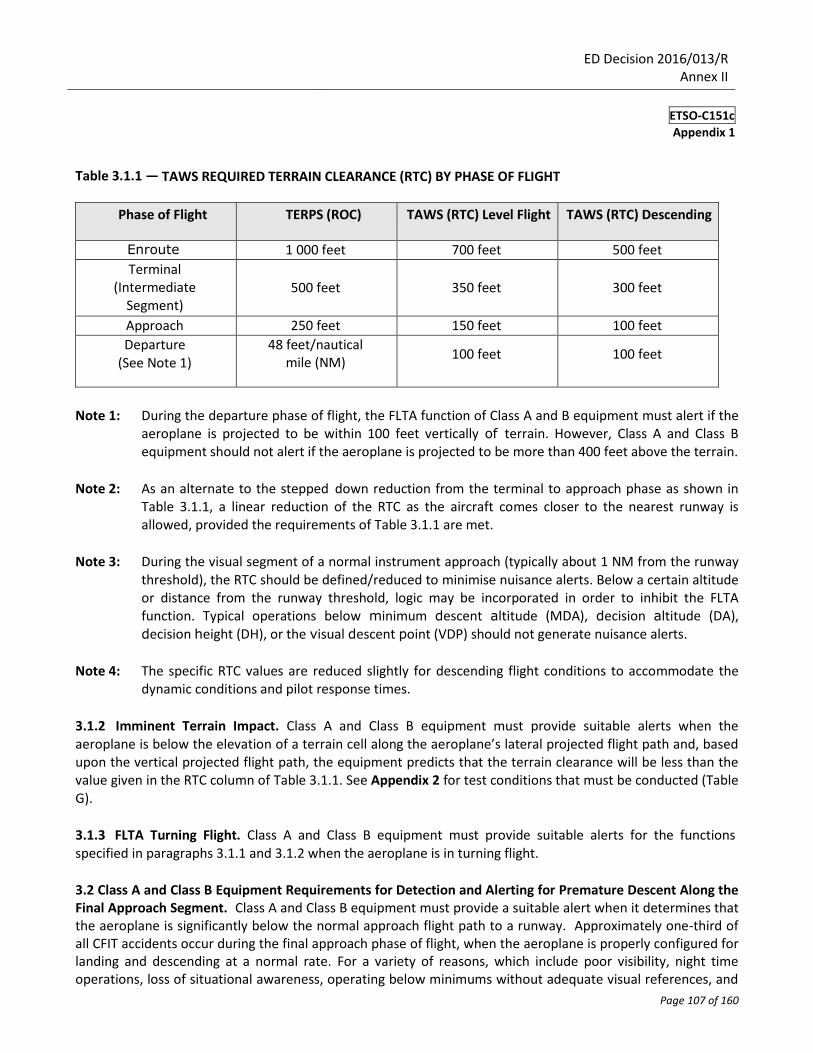
Table 3.1.1 — TAWS REQUIRED TERRAIN CLEARANCE (RTC) BY PHASE OF FLIGHT
Phase of Flight TERPS (ROC) TAWS (RTC) Level Flight TAWS (RTC) Descending
Enroute 1 000 feet 700 feet 500 feet
Terminal (Intermediate
Segment)
500 feet
350 feet
300 feet
Approach 250 feet 150 feet 100 feet
Departure (See Note 1)
48 feet/nautical mile (NM)
100 feet
100 feet
Note 1: During the departure phase of flight, the FLTA function of Class A and B equipment must alert if the aeroplane is projected to be within 100 feet vertically of terrain. However, Class A and Class B equipment should not alert if the aeroplane is projected to be more than 400 feet above the terrain.
Note 2: As an alternate to the stepped down reduction from the terminal to approach phase as shown in
Table 3.1.1, a linear reduction of the RTC as the aircraft comes closer to the nearest runway is allowed, provided the requirements of Table 3.1.1 are met.
Note 3: During the visual segment of a normal instrument approach (typically about 1 NM from the runway
threshold), the RTC should be defined/reduced to minimise nuisance alerts. Below a certain altitude or distance from the runway threshold, logic may be incorporated in order to inhibit the FLTA function. Typical operations below minimum descent altitude (MDA), decision altitude (DA), decision height (DH), or the visual descent point (VDP) should not generate nuisance alerts.
Note 4: The specific RTC values are reduced slightly for descending flight conditions to accommodate the
dynamic conditions and pilot response times.
3.1.2 Imminent Terrain Impact. Class A and Class B equipment must provide suitable alerts when the aeroplane is below the elevation of a terrain cell along the aeroplane’s lateral projected flight path and, based upon the vertical projected flight path, the equipment predicts that the terrain clearance will be less than the value given in the RTC column of Table 3.1.1. See Appendix 2 for test conditions that must be conducted (Table G).
3.1.3 FLTA Turning Flight. Class A and Class B equipment must provide suitable alerts for the functions specified in paragraphs 3.1.1 and 3.1.2 when the aeroplane is in turning flight.
3.2 Class A and Class B Equipment Requirements for Detection and Alerting for Premature Descent Along the Final Approach Segment. Class A and Class B equipment must provide a suitable alert when it determines that the aeroplane is significantly below the normal approach flight path to a runway. Approximately one-third of all CFIT accidents occur during the final approach phase of flight, when the aeroplane is properly configured for landing and descending at a normal rate. For a variety of reasons, which include poor visibility, night time operations, loss of situational awareness, operating below minimums without adequate visual references, and

ED Decision 2016/013/R Annex II
ETSO-C151c
Appendix 1
Page 108 of 160
deviations from the published approach procedures, many aeroplanes have crashed into the ground short of the runway. Detection of this condition and alerting the flight crew is an essential safety requirement of this ETSO, and there are numerous ways to accomplish these overall objectives. Alerting criteria may be based upon height above runway elevation and distance to runway. It may be based upon height above the terrain and distance to runway or other suitable means. This ETSO will not define the surfaces for which alerting is required. Instead, it specifies some general requirements for alerting and some cases when alerting is inappropriate. See Appendix 2, Table H, for test requirements.
a. The PDA function must be available for all types of instrument approaches. This includes both straight-in
approaches and circling approaches.
b. The TAWS equipment must not generate PDA alerts for normal visual flight rules (VFR) operations in the
airport area. Aeroplanes routinely operate at traffic pattern altitudes of 800 feet above field/runway elevation when within 5 NM of the airport.
c. Aeroplanes routinely operate in VFR conditions at 1 000 feet above ground level (AGL) within
10–15 NM of the nearest airport, and these operations must not generate alerts.
d. Aeroplanes routinely operate in the visual segment of a circling approach within 2 NM of the
airport/runway of intended landing, with 300 feet of obstacle clearance. Operations at circling minimums must not cause PDA or FLTA alerts.
3.3 Class A Requirements for Ground Proximity Warning System (GPWS) Alerting. In addition to the TAWS FLTA and PDA functions, the equipment must provide the Mode 1 through Mode 5 GPWS functions listed below in accordance with ETSO-C92c and the altitude callout function in accordance with paragraph 3.3.c. of this Appendix. However, it is essential to retain the independent protective features provided by both the GPWS and FLTA functions. In each case, all of the following modes must be covered. Some GPWS alerting thresholds may be adjusted or modified to be more compatible with the FLTA alerting function and to minimise GPWS nuisance alerts. Modifications to the GPWS requirements require an approved deviation in accordance with Part-21, 21.A.610. The failure of the ETSO-C92c equipment functions, except for power supply failure, input sensor failure, or failure of other common portions of the equipment, must not cause a loss of the FLTA, PDA, or terrain display.
— Mode 1: Excessive rate of descent
— Mode 2: Excessive closure rate to terrain
— Mode 3: Negative climb rate or altitude loss after takeoff
— Mode 4: Flight into terrain when not in landing configuration
— Mode 5: Excessive downward deviation from an ILS glideslope, LPV, and/or GLS glidepath
— Altitude Callout: Five Hundred Foot Voice Callout
ED Decision 2016/013/R Annex II
ETSO-C151c
Appendix 1
Page 109 of 160
a. Flap Alerting Inhibition. A separate, guarded control may be provided to inhibit Mode 4 alerts based on flaps being other than landing configuration.
b. Speed. Airspeed or groundspeed must be included in the logic that determines basic GPWS alerting time
for ‘excessive closure rate to terrain’ and ‘flight into terrain when not in landing configuration’ to allow maximum time for the flight crew to react and take corrective action.
c. Altitude Callouts. Class A equipment must provide a voice callout of ‘five hundred’ or equivalent when
descending through 500 feet above terrain or 500 feet above the nearest runway elevation during nonprecision approaches, but are recommended for all approaches. Additional altitude callouts, such as ‘one hundred’ or ‘two hundred’ are acceptable, but not required. This voice callout will not be made at ascent, for example on a missed approach or departure.
d. Sweep Tones ‘Whoop-Whoop’. If a two-tone sweep is used to comply with RTCA/DO-161A, paragraph
2.3, the complete cycle of two-tone sweeps plus annunciation may be extended from ‘1.4’ to ‘2’ seconds.
e. Mode 5 Glidepath Deviation Alerting. Class A TAWS equipment must provide Mode 5 alerting for
localizer performance with vertical guidance (LPV) glidepath and GNSS landing system (GLS) glidepath, as well as the ILS glideslope. The LPV and GLS envelope, deactivation, reactivation, arming, disarming, alert requirements must follow the Mode 5 requirements in RTCA/DO-161A. The FAA recommends that the glidepath aural alert for LPV and GLS approaches say ‘glidepath’ or equivalent, but the use of “glideslope” is also acceptable. Follow test guidance in RTCA/DO-161A.
3.4 Class B Requirements for GPWS Alerting
a. Class B equipment must provide alerts for excessive descent rates. The Mode 1 alerting envelope of RTCA/DO-161A was modified to accommodate a larger envelope for both caution and warning alerts. Height above terrain may be determined by using the terrain database elevation and subtracting it from the QNH (corrected) barometric altitude, or GNSS altitude (or equivalent). In addition, since the envelopes are not limited by a radio altitude measurement to a maximum of 2 500 feet AGL, the envelopes are expanded to include higher vertical speeds. The equipment must meet either the requirements set forth in Appendix 2, paragraph 7.0, or those specified in RTCA/DO-161A.
b. Class B equipment must provide alerts for ‘negative climb rate after takeoff or missed approach’ or
‘altitude loss after takeoff,’ as specified in RTCA/DO-161A. The alerting envelopes are identical to the Mode 3 alerting envelopes in RTCA/DO-161A. Height above terrain may be determined by comparison of aircraft altitude (GNSS or barometric) with runway threshold elevation or by radio altimeter.
c. This feature also has an important CFIT protection function. In the event the aeroplane is operated
unintentionally close to terrain when not in the airport area or the area for which PDA protection is provided, this voice callout will alert the flight crew to hazardous conditions. The equipment must meet the requirements specified in Appendix 2, section 9.0. Class B TAWS equipment must provide a 500 foot voice call out when descending through 500 feet above the runway threshold elevation for landing. This feature is primarily intended to provide situational awareness to the flight crew when the aeroplane is being operated properly, per normal procedures. During a normal approach, it is useful to provide the
ED Decision 2016/013/R Annex II
ETSO-C151c
Appendix 1
Page 110 of 160
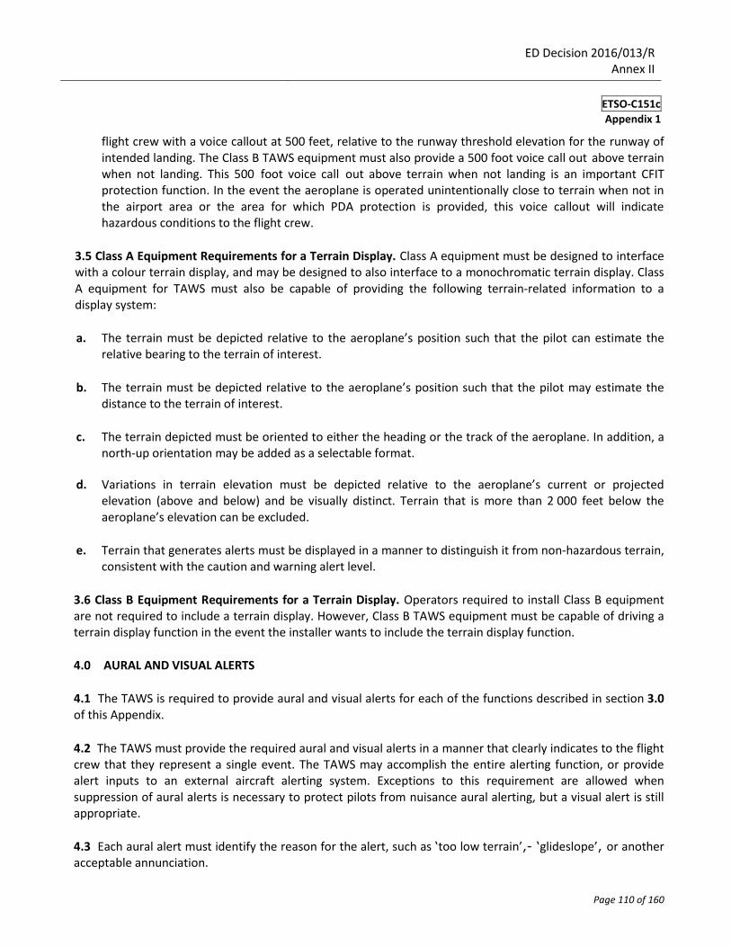
flight crew with a voice callout at 500 feet, relative to the runway threshold elevation for the runway of intended landing. The Class B TAWS equipment must also provide a 500 foot voice call out above terrain when not landing. This 500 foot voice call out above terrain when not landing is an important CFIT protection function. In the event the aeroplane is operated unintentionally close to terrain when not in the airport area or the area for which PDA protection is provided, this voice callout will indicate hazardous conditions to the flight crew.
3.5 Class A Equipment Requirements for a Terrain Display. Class A equipment must be designed to interface with a colour terrain display, and may be designed to also interface to a monochromatic terrain display. Class A equipment for TAWS must also be capable of providing the following terrain-related information to a display system:
a. The terrain must be depicted relative to the aeroplane’s position such that the pilot can estimate the
relative bearing to the terrain of interest.
b. The terrain must be depicted relative to the aeroplane’s position such that the pilot may estimate the
distance to the terrain of interest.
c. The terrain depicted must be oriented to either the heading or the track of the aeroplane. In addition, a
north-up orientation may be added as a selectable format.
d. Variations in terrain elevation must be depicted relative to the aeroplane’s current or projected elevation (above and below) and be visually distinct. Terrain that is more than 2 000 feet below the aeroplane’s elevation can be excluded.
e. Terrain that generates alerts must be displayed in a manner to distinguish it from non-hazardous terrain,
consistent with the caution and warning alert level.
3.6 Class B Equipment Requirements for a Terrain Display. Operators required to install Class B equipment are not required to include a terrain display. However, Class B TAWS equipment must be capable of driving a terrain display function in the event the installer wants to include the terrain display function.
4.0 AURAL AND VISUAL ALERTS
4.1 The TAWS is required to provide aural and visual alerts for each of the functions described in section 3.0 of this Appendix.
4.2 The TAWS must provide the required aural and visual alerts in a manner that clearly indicates to the flight crew that they represent a single event. The TAWS may accomplish the entire alerting function, or provide alert inputs to an external aircraft alerting system. Exceptions to this requirement are allowed when suppression of aural alerts is necessary to protect pilots from nuisance aural alerting, but a visual alert is still appropriate.
4.3 Each aural alert must identify the reason for the alert, such as ‘too low terrain’,- ‘glideslope’, or another acceptable annunciation.
ED Decision 2016/013/R Annex II
ETSO-C151c
Appendix 1
Page 111 of 160
4.4 The system must remove the visual and aural alert once the situation has been resolved.
4.5 The system must be capable of accepting and processing aeroplane performance-related data or aeroplane dynamic data and providing the capability to update aural and visual alerts at least once per second.
4.6 The aural and visual outputs as defined in Table 4-1 must be compatible with the standard cockpit displays and auditory systems.
4.7 The aural and visual alerts should be selectable to accommodate operational commonality among aeroplane fleets.
4.8 The visual display of alerting information must be immediately and continuously displayed until the situation is resolved or no longer valid.
4.9 At a minimum, the TAWS must be capable of providing aural alert messages described in Table 4-1. In addition to this minimum set, other voice alerts may be provided.
ED Decision 2016/013/R Annex II
ETSO-C151c
Appendix 1
Page 112 of 160
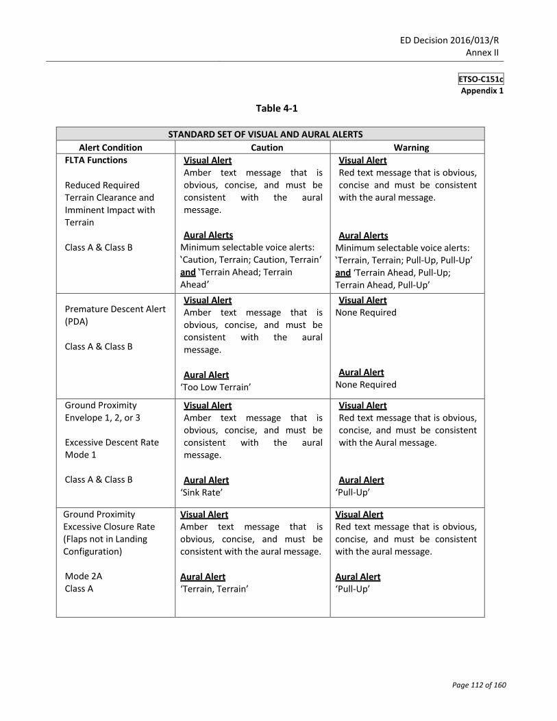
Table 4-1
STANDARD SET OF VISUAL AND AURAL ALERTS
Alert Condition Caution Warning FLTA Functions
Reduced Required Terrain Clearance and Imminent Impact with Terrain
Class A & Class B
Visual Alert Amber text message that is obvious, concise, and must be consistent with the aural message.
Aural Alerts
Minimum selectable voice alerts: ‘Caution, Terrain; Caution, Terrain’ and ‘Terrain Ahead; Terrain Ahead’
Visual Alert Red text message that is obvious, concise and must be consistent with the aural message.
Aural Alerts
Minimum selectable voice alerts: ‘Terrain, Terrain; Pull-Up, Pull-Up’ and ‘Terrain Ahead, Pull-Up; Terrain Ahead, Pull-Up’
Premature Descent Alert (PDA)
Class A & Class B
Visual Alert Amber text message that is obvious, concise, and must be consistent with the aural message.
Aural Alert
‘Too Low Terrain’
Visual Alert None Required Aural Alert
None Required
Ground Proximity Envelope 1, 2, or 3 Excessive Descent Rate Mode 1 Class A & Class B
Visual Alert Amber text message that is obvious, concise, and must be consistent with the aural message.
Aural Alert
‘Sink Rate’
Visual Alert Red text message that is obvious, concise, and must be consistent with the Aural message.
Aural Alert
‘Pull-Up’
Ground Proximity Excessive Closure Rate (Flaps not in Landing Configuration) Mode 2A Class A
Visual Alert Amber text message that is obvious, concise, and must be consistent with the aural message.
Aural Alert ‘Terrain, Terrain’
Visual Alert Red text message that is obvious, concise, and must be consistent with the aural message.
Aural Alert ‘Pull-Up’
ED Decision 2016/013/R Annex II
ETSO-C151c
Appendix 1
Page 113 of 160
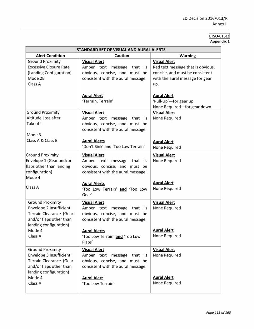
STANDARD SET OF VISUAL AND AURAL ALERTS
Alert Condition Caution Warning
Ground Proximity Excessive Closure Rate (Landing Configuration) Mode 2B Class A
Visual Alert Amber text message that is obvious, concise, and must be consistent with the aural message.
Aural Alert ‘Terrain, Terrain’
Visual Alert Red text message that is obvious, concise, and must be consistent with the aural message for gear up.
Aural Alert ‘Pull-Up’—for gear up None Required—for gear down
Ground Proximity Altitude Loss after Takeoff
Mode 3 Class A & Class B
Visual Alert Amber text message that is obvious, concise, and must be consistent with the aural message.
Aural Alerts ‘Don’t Sink’ and ‘Too Low Terrain’
Visual Alert None Required
Aural Alert None Required
Ground Proximity Envelope 1 (Gear and/or flaps other than landing configuration) Mode 4 Class A
Visual Alert Amber text message that is obvious, concise, and must be consistent with the aural message.
Aural Alerts ‘Too Low Terrain’ and ‘Too Low Gear’
Visual Alert None Required
Aural Alert None Required
Ground Proximity Envelope 2 Insufficient Terrain Clearance (Gear and/or flaps other than landing configuration) Mode 4 Class A
Visual Alert Amber text message that is obvious, concise, and must be consistent with the aural message.
Aural Alerts ‘Too Low Terrain’ and ‘Too Low Flaps’
Visual Alert None Required
Aural Alert None Required
Ground Proximity Envelope 3 Insufficient Terrain Clearance (Gear and/or flaps other than landing configuration) Mode 4 Class A
Visual Alert Amber text message that is obvious, concise, and must be consistent with the aural message.
Aural Alert ‘Too Low Terrain’
Visual Alert None Required
Aural Alert None Required
ED Decision 2016/013/R Annex II
ETSO-C151c
Appendix 1
Page 114 of 160
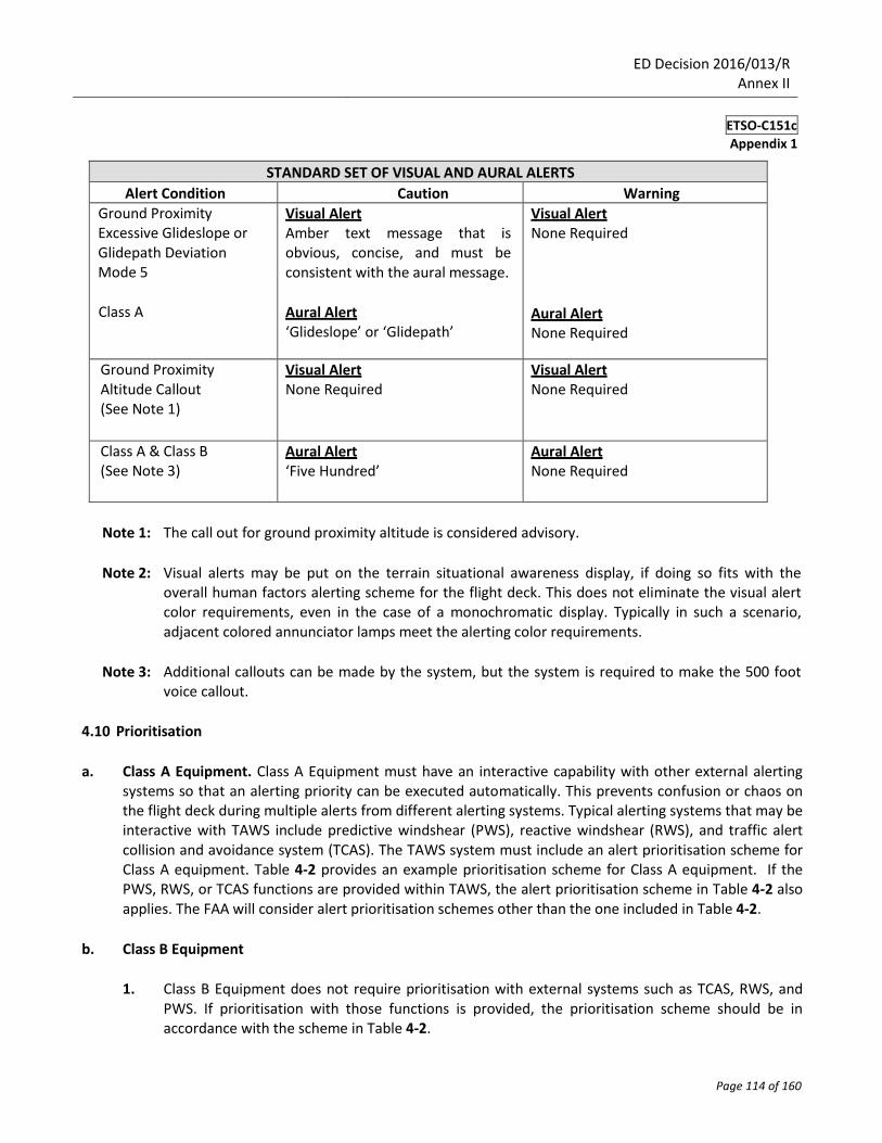
STANDARD SET OF VISUAL AND AURAL ALERTS
Alert Condition Caution Warning
Ground Proximity Excessive Glideslope or Glidepath Deviation Mode 5
Class A
Visual Alert Amber text message that is obvious, concise, and must be consistent with the aural message.
Aural Alert ‘Glideslope’ or ‘Glidepath’
Visual Alert None Required
Aural Alert None Required
Ground Proximity Altitude Callout (See Note 1)
Visual Alert None Required
Visual Alert None Required
Class A & Class B (See Note 3)
Aural Alert ‘Five Hundred’
Aural Alert None Required
Note 1: The call out for ground proximity altitude is considered advisory.
Note 2: Visual alerts may be put on the terrain situational awareness display, if doing so fits with the
overall human factors alerting scheme for the flight deck. This does not eliminate the visual alert color requirements, even in the case of a monochromatic display. Typically in such a scenario, adjacent colored annunciator lamps meet the alerting color requirements.
Note 3: Additional callouts can be made by the system, but the system is required to make the 500 foot
voice callout.
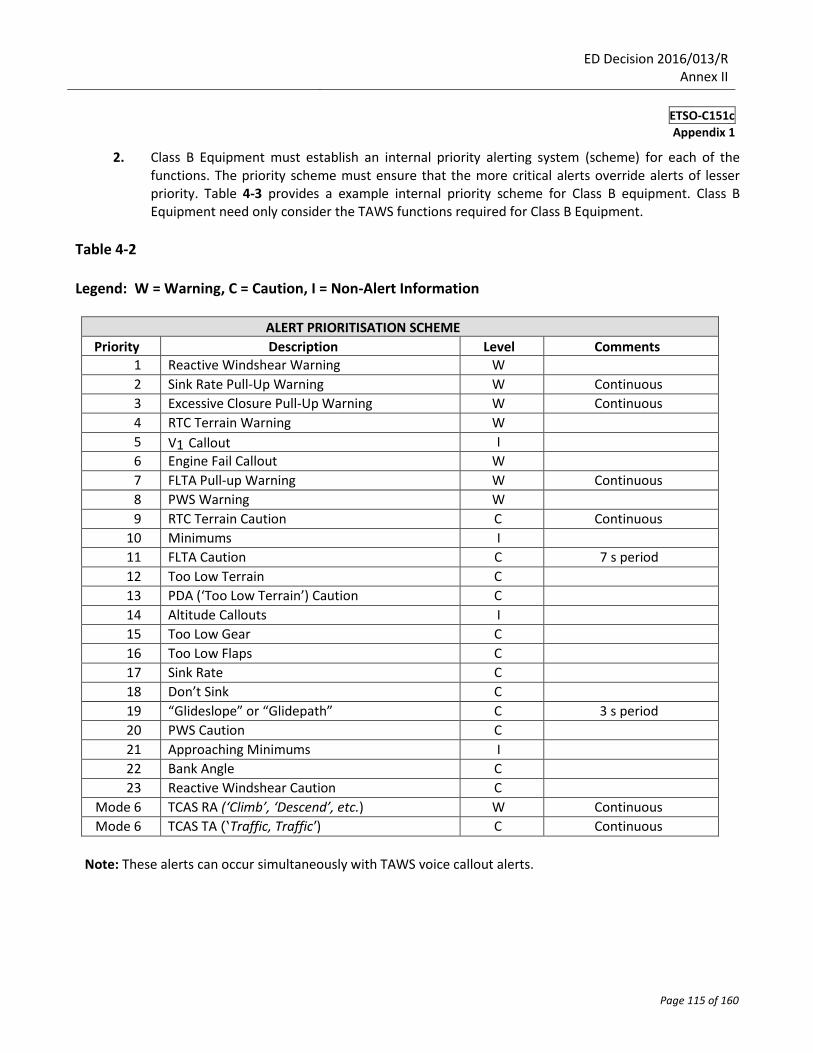
4.10 Prioritisation
a. Class A Equipment. Class A Equipment must have an interactive capability with other external alerting
systems so that an alerting priority can be executed automatically. This prevents confusion or chaos on the flight deck during multiple alerts from different alerting systems. Typical alerting systems that may be interactive with TAWS include predictive windshear (PWS), reactive windshear (RWS), and traffic alert collision and avoidance system (TCAS). The TAWS system must include an alert prioritisation scheme for Class A equipment. Table 4-2 provides an example prioritisation scheme for Class A equipment. If the PWS, RWS, or TCAS functions are provided within TAWS, the alert prioritisation scheme in Table 4-2 also applies. The FAA will consider alert prioritisation schemes other than the one included in Table 4-2.
b. Class B Equipment
1. Class B Equipment does not require prioritisation with external systems such as TCAS, RWS, and
PWS. If prioritisation with those functions is provided, the prioritisation scheme should be in accordance with the scheme in Table 4-2.
ED Decision 2016/013/R Annex II
ETSO-C151c
Appendix 1
Page 115 of 160
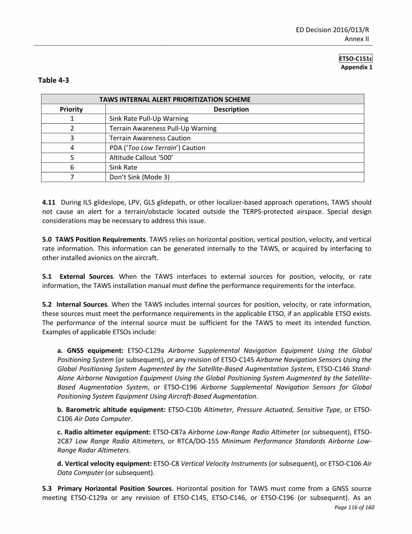
2. Class B Equipment must establish an internal priority alerting system (scheme) for each of the functions. The priority scheme must ensure that the more critical alerts override alerts of lesser priority. Table 4-3 provides a example internal priority scheme for Class B equipment. Class B Equipment need only consider the TAWS functions required for Class B Equipment.
Table 4-2 Legend: W = Warning, C = Caution, I = Non-Alert Information
ALERT PRIORITISATION SCHEME
Priority Description Level Comments 1 Reactive Windshear Warning W
2 Sink Rate Pull-Up Warning W Continuous
3 Excessive Closure Pull-Up Warning W Continuous
4 RTC Terrain Warning W
5 V1 Callout I
6 Engine Fail Callout W
7 FLTA Pull-up Warning W Continuous
8 PWS Warning W
9 RTC Terrain Caution C Continuous
10 Minimums I
11 FLTA Caution C 7 s period
12 Too Low Terrain C
13 PDA (‘Too Low Terrain’) Caution C
14 Altitude Callouts I
15 Too Low Gear C
16 Too Low Flaps C
17 Sink Rate C
18 Don’t Sink C
19 “Glideslope” or “Glidepath” C 3 s period
20 PWS Caution C
21 Approaching Minimums I
22 Bank Angle C
23 Reactive Windshear Caution C
Mode 6 TCAS RA (‘Climb’, ‘Descend’, etc.) W Continuous
Mode 6 TCAS TA (‘Traffic, Traffic’) C Continuous
Note: These alerts can occur simultaneously with TAWS voice callout alerts.
ED Decision 2016/013/R Annex II
ETSO-C151c
Appendix 1
Page 116 of 160
Table 4-3
TAWS INTERNAL ALERT PRIORITIZATION SCHEME
Priority Description 1 Sink Rate Pull-Up Warning
2 Terrain Awareness Pull-Up Warning
3 Terrain Awareness Caution
4 PDA (‘Too Low Terrain’) Caution
5 Altitude Callout ‘500’
6 Sink Rate
7 Don’t Sink (Mode 3)
4.11 During ILS glideslope, LPV, GLS glidepath, or other localizer-based approach operations, TAWS should not cause an alert for a terrain/obstacle located outside the TERPS-protected airspace. Special design considerations may be necessary to address this issue.
5.0 TAWS Position Requirements. TAWS relies on horizontal position, vertical position, velocity, and vertical rate information. This information can be generated internally to the TAWS, or acquired by interfacing to other installed avionics on the aircraft.
5.1 External Sources. When the TAWS interfaces to external sources for position, velocity, or rate information, the TAWS installation manual must define the performance requirements for the interface.
5.2 Internal Sources. When the TAWS includes internal sources for position, velocity, or rate information, these sources must meet the performance requirements in the applicable ETSO, if an applicable ETSO exists. The performance of the internal source must be sufficient for the TAWS to meet its intended function. Examples of applicable ETSOs include:
a. GNSS equipment: ETSO-C129a Airborne Supplemental Navigation Equipment Using the Global Positioning System (or subsequent), or any revision of ETSO-C145 Airborne Navigation Sensors Using the Global Positioning System Augmented by the Satellite-Based Augmentation System, ETSO-C146 Stand-Alone Airborne Navigation Equipment Using the Global Positioning System Augmented by the Satellite-Based Augmentation System, or ETSO-C196 Airborne Supplemental Navigation Sensors for Global Positioning System Equipment Using Aircraft-Based Augmentation.
b. Barometric altitude equipment: ETSO-C10b Altimeter, Pressure Actuated, Sensitive Type, or ETSO-C106 Air Data Computer.
c. Radio altimeter equipment: ETSO-C87a Airborne Low-Range Radio Altimeter (or subsequent), ETSO-2C87 Low Range Radio Altimeters, or RTCA/DO-155 Minimum Performance Standards Airborne Low-Range Radar Altimeters.
d. Vertical velocity equipment: ETSO-C8 Vertical Velocity Instruments (or subsequent), or ETSO-C106 Air Data Computer (or subsequent).
5.3 Primary Horizontal Position Sources. Horizontal position for TAWS must come from a GNSS source meeting ETSO-C129a or any revision of ETSO-C145, ETSO-C146, or ETSO-C196 (or subsequent). As an
ED Decision 2016/013/R Annex II
ETSO-C151c
Appendix 1
Page 117 of 160
exception, TAWS equipment limited to installation in aircraft where the EU Regulation on Air Operations does not require such equipment may be configurable to operate solely on a non-GNSS position source.
5.4 Alternate Horizontal Position Sources. Retaining TAWS functionality during GNSS outage or unavailability provides a safety benefit. It is acceptable and recommended to incorporate a secondary, non GNSS position source, to provide horizontal position when the GNSS is not available or reliable.
5.5 Vertical Position Sources. Vertical position for TAWS may come from a barometric source, such as an altimeter or an air data computer, or from a geometric source, such as GNSS. GNSS vertical accuracy, at a minimum, must meet RTCA/DO-229D, section 2.2.3.3.4. Designs that cross check barometric and geometric altitude are recommended. Class A TAWS also requires a radio altimeter.
5.6 Position Source Faults. If a position source generates a fault indication or any flag indicating the position is invalid or does not meet performance requirements, the TAWS must stop utilizing that position source. The TAWS may revert to an alternate position source, and must provide indications, as appropriate, regarding loss of function associated with the loss of the position source. The TAWS must inhibit FLTA and PDA alerts when the position source in use is faulted or invalid.
6.0 CLASS A AND CLASS B REQUIREMENTS FOR A TERRAIN AND AIRPORT DATABASE
6.1 Minimum Geographical Consideration. At a minimum, terrain and airport information must be provided for the expected areas of operation, airports, and routes flown.
6.2 Development and Methodology. The manufacturer must present the development methodology used to validate and verify the terrain and airport information. RTCA/DO-200A/ED-76 Standards for Processing Aeronautical Data should be used as a guideline.
6.3 Resolution. Terrain and airport information must be accurate and of acceptable resolution in order for the system to perform its intended function. Terrain data should be gridded at 30 arc seconds with 100-foot resolution within 30 NM of all airports with runway lengths of 3 500 feet or greater, and whenever necessary (particularly in mountainous environments), 15 arc seconds with 100-foot resolution (or even 6 arc seconds) within 6 NM of the closest runway. It is acceptable to have terrain data gridded in larger segments over oceanic and remote areas around the world.
Note: Class B equipment may require information relative to airports with runways less than 3 500 feet
whether public or private. Small aeroplane owners and operators will likely be the largest market for Class B equipment and they frequently use airports of less than 3 500 feet. Those TAWS manufacturers who desire to sell to this market must be willing to customize their terrain databases to include selected airports used by their customers.
6.4 Continued Airworthiness Updates. The system must be capable of accepting updated terrain and airport information. Updating of terrain, obstacle, and airport databases does not require a change to the ETSO authorization.
7.0 CLASS A AND CLASS B FAILURE INDICATION. Class A and Class B equipment must include a failure monitor function that provides reliable indications of equipment condition during operation. It must monitor
ED Decision 2016/013/R Annex II
ETSO-C151c
Appendix 1
Page 118 of 160
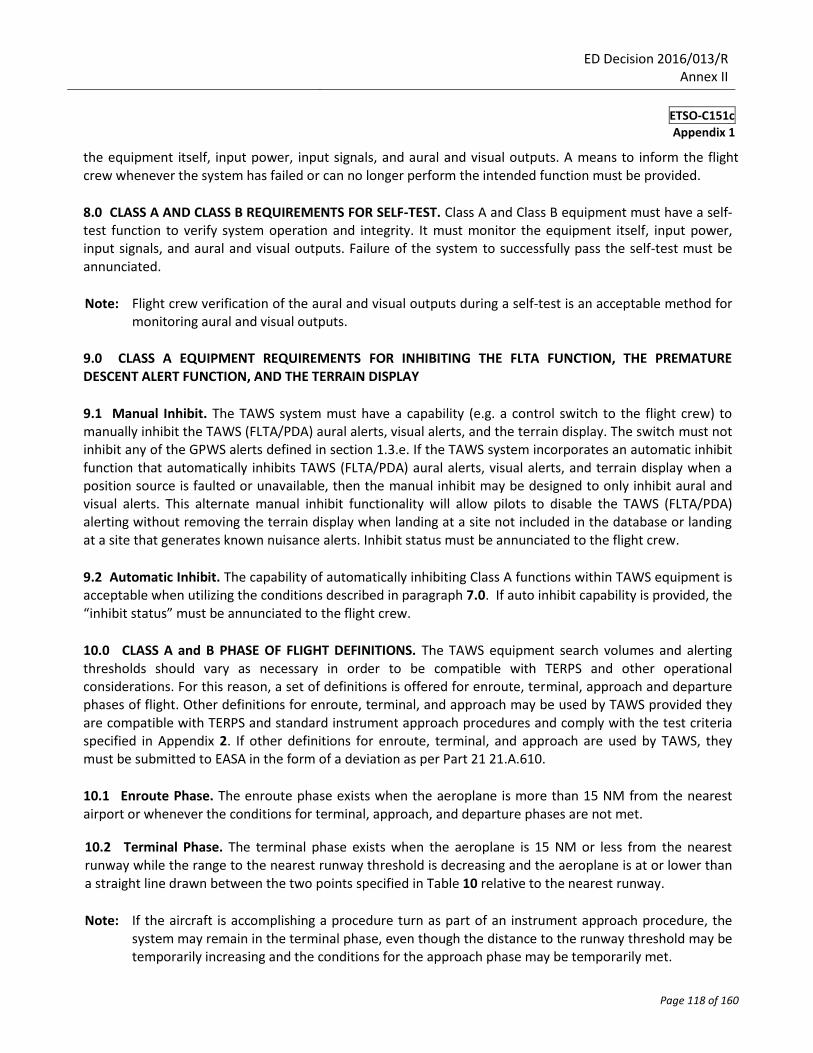
the equipment itself, input power, input signals, and aural and visual outputs. A means to inform the flight crew whenever the system has failed or can no longer perform the intended function must be provided.
8.0 CLASS A AND CLASS B REQUIREMENTS FOR SELF-TEST. Class A and Class B equipment must have a self-test function to verify system operation and integrity. It must monitor the equipment itself, input power, input signals, and aural and visual outputs. Failure of the system to successfully pass the self-test must be annunciated.
Note: Flight crew verification of the aural and visual outputs during a self-test is an acceptable method for
monitoring aural and visual outputs.
9.0 CLASS A EQUIPMENT REQUIREMENTS FOR INHIBITING THE FLTA FUNCTION, THE PREMATURE DESCENT ALERT FUNCTION, AND THE TERRAIN DISPLAY
9.1 Manual Inhibit. The TAWS system must have a capability (e.g. a control switch to the flight crew) to manually inhibit the TAWS (FLTA/PDA) aural alerts, visual alerts, and the terrain display. The switch must not inhibit any of the GPWS alerts defined in section 1.3.e. If the TAWS system incorporates an automatic inhibit function that automatically inhibits TAWS (FLTA/PDA) aural alerts, visual alerts, and terrain display when a position source is faulted or unavailable, then the manual inhibit may be designed to only inhibit aural and visual alerts. This alternate manual inhibit functionality will allow pilots to disable the TAWS (FLTA/PDA) alerting without removing the terrain display when landing at a site not included in the database or landing at a site that generates known nuisance alerts. Inhibit status must be annunciated to the flight crew.
9.2 Automatic Inhibit. The capability of automatically inhibiting Class A functions within TAWS equipment is acceptable when utilizing the conditions described in paragraph 7.0. If auto inhibit capability is provided, the “inhibit status” must be annunciated to the flight crew.
10.0 CLASS A and B PHASE OF FLIGHT DEFINITIONS. The TAWS equipment search volumes and alerting thresholds should vary as necessary in order to be compatible with TERPS and other operational considerations. For this reason, a set of definitions is offered for enroute, terminal, approach and departure phases of flight. Other definitions for enroute, terminal, and approach may be used by TAWS provided they are compatible with TERPS and standard instrument approach procedures and comply with the test criteria specified in Appendix 2. If other definitions for enroute, terminal, and approach are used by TAWS, they must be submitted to EASA in the form of a deviation as per Part 21 21.A.610.
10.1 Enroute Phase. The enroute phase exists when the aeroplane is more than 15 NM from the nearest airport or whenever the conditions for terminal, approach, and departure phases are not met.
10.2 Terminal Phase. The terminal phase exists when the aeroplane is 15 NM or less from the nearest runway while the range to the nearest runway threshold is decreasing and the aeroplane is at or lower than a straight line drawn between the two points specified in Table 10 relative to the nearest runway.
Note: If the aircraft is accomplishing a procedure turn as part of an instrument approach procedure, the
system may remain in the terminal phase, even though the distance to the runway threshold may be temporarily increasing and the conditions for the approach phase may be temporarily met.
ED Decision 2016/013/R Annex II
ETSO-C151c
Appendix 1
Page 119 of 160
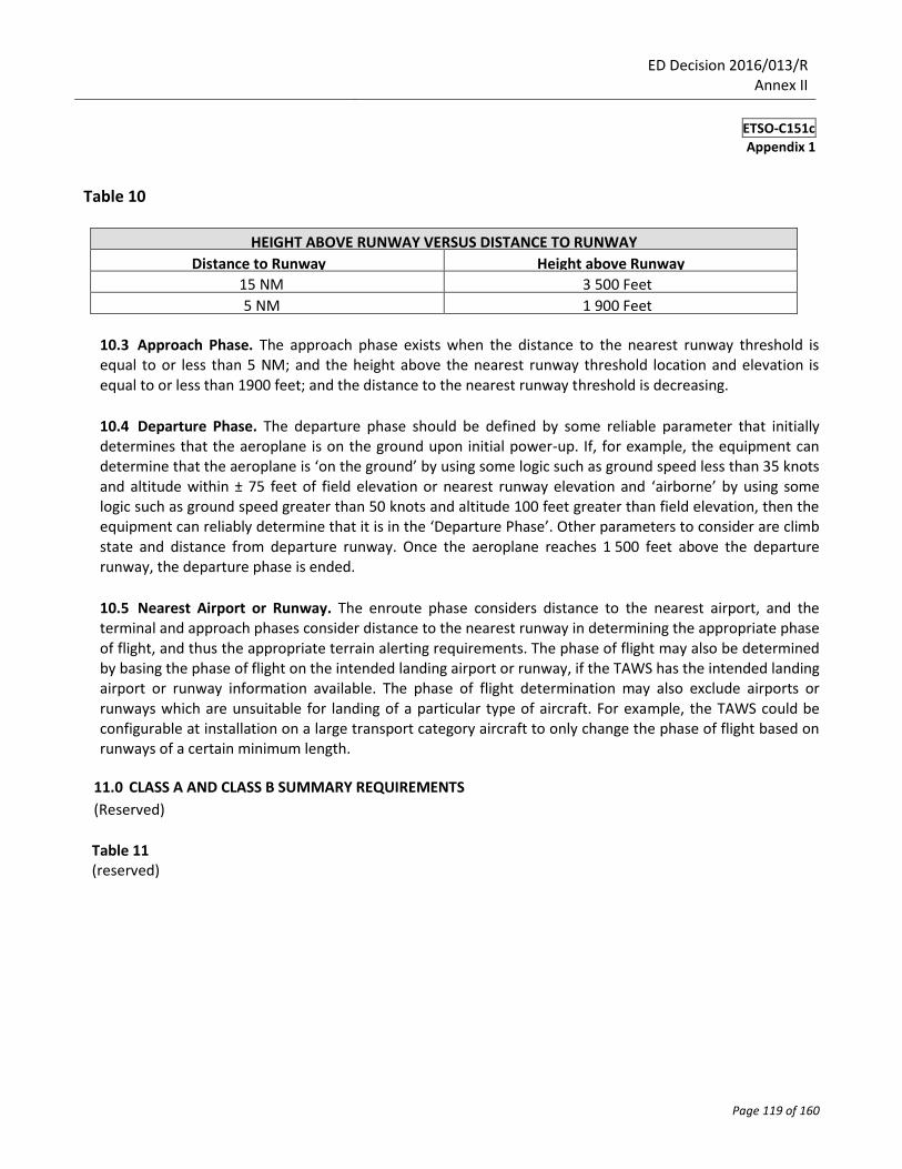
Table 10
HEIGHT ABOVE RUNWAY VERSUS DISTANCE TO RUNWAY
Distance to Runway Height above Runway
15 NM 3 500 Feet
5 NM 1 900 Feet
10.3 Approach Phase. The approach phase exists when the distance to the nearest runway threshold is equal to or less than 5 NM; and the height above the nearest runway threshold location and elevation is equal to or less than 1900 feet; and the distance to the nearest runway threshold is decreasing.
10.4 Departure Phase. The departure phase should be defined by some reliable parameter that initially determines that the aeroplane is on the ground upon initial power-up. If, for example, the equipment can determine that the aeroplane is ‘on the ground’ by using some logic such as ground speed less than 35 knots and altitude within ± 75 feet of field elevation or nearest runway elevation and ‘airborne’ by using some logic such as ground speed greater than 50 knots and altitude 100 feet greater than field elevation, then the equipment can reliably determine that it is in the ‘Departure Phase’. Other parameters to consider are climb state and distance from departure runway. Once the aeroplane reaches 1 500 feet above the departure runway, the departure phase is ended.
10.5 Nearest Airport or Runway. The enroute phase considers distance to the nearest airport, and the terminal and approach phases consider distance to the nearest runway in determining the appropriate phase of flight, and thus the appropriate terrain alerting requirements. The phase of flight may also be determined by basing the phase of flight on the intended landing airport or runway, if the TAWS has the intended landing airport or runway information available. The phase of flight determination may also exclude airports or runways which are unsuitable for landing of a particular type of aircraft. For example, the TAWS could be configurable at installation on a large transport category aircraft to only change the phase of flight based on runways of a certain minimum length.
11.0 CLASS A AND CLASS B SUMMARY REQUIREMENTS
(Reserved)
Table 11 (reserved)
ED Decision 2016/013/R Annex II
ETSO-C151c
Appendix 2
Page 120 of 160
APPENDIX 2
TEST CONDITIONS
1.0 FORWARD-LOOKING TERRAIN AVOIDANCE — REDUCED REQUIRED TERRAIN CLEARANCE (RTC) TEST CONDITIONS. These conditions exist when the aeroplane is currently above the terrain, but the combination of current altitude, height above terrain, and projected flight path indicates that there is a significant reduction in the RTC.
1.1 Phase of Flight Definitions. For the following test conditions, refer to Appendix 1, paragraph 10.0, for
an expanded explanation of the definitions of the phases of flight.
1.2 En route Descent Requirement. A terrain alert must be provided in time to ensure that the aeroplane can level off (L/O) with a minimum of 500 feet altitude clearance over the terrain/obstacle when descending toward the terrain/obstacle at any speed within the operational flight envelope of the aeroplane. The test conditions assume a descent along a flight path with terrain that is 1 000 feet below the expected L/O altitude. If the pilot initiates the L/O at the proper altitude, no TAWS alert is expected. However, if the pilot is distracted or otherwise delays the L/O, a TAWS alert is required to permit the pilot to recover to level flight in a safe manner.
Note: The L/O initiation height of 20 % of the vertical speed was chosen (as a minimum standard for
nuisance alarm-free operations) because it is similar to typical autopilot or flight director L/O (altitude capture) algorithms. In contrast, the technique of using 10 %of the existing vertical speed as a L/O initiation point is usually considered a minimum, appropriate only to manual operations of smaller general aviation (GA) aeroplanes. With high rates of descent, experienced pilots often use a manual technique of reducing the vertical speed by one half when reaching 1 000 feet above/below the L/O altitude. This technique will significantly reduce the likelihood of nuisance alerts. In the event that using 20 %of the vertical speed as a minimum standard for nuisance-free operations is shown not to be compatible with the installed autopilot or flight director L/O (altitude capture) algorithms, consideration should be given to setting the alert logic closer to the 10 %vertical speed criteria to minimize nuisance alerts.
a. Table A, column A, represents the test condition. Columns B, C, and D are for information purposes only. Column E represents the minimum altitude for which TAWS alerts must be posted to perform their intended function. Column F represents the maximum altitude for which TAWS alerts may be provided in order to meet the nuisance alert criteria. See Appendix 2, paragraph 4.0.
b. For each of the descent rates specified below, recovery to level flight at or above 500 feet terrain clearance is required.
c. Test conditions for enroute descent requirement:
ED Decision 2016/013/R Annex II
ETSO-C151c
Appendix 2
Page 121 of 160
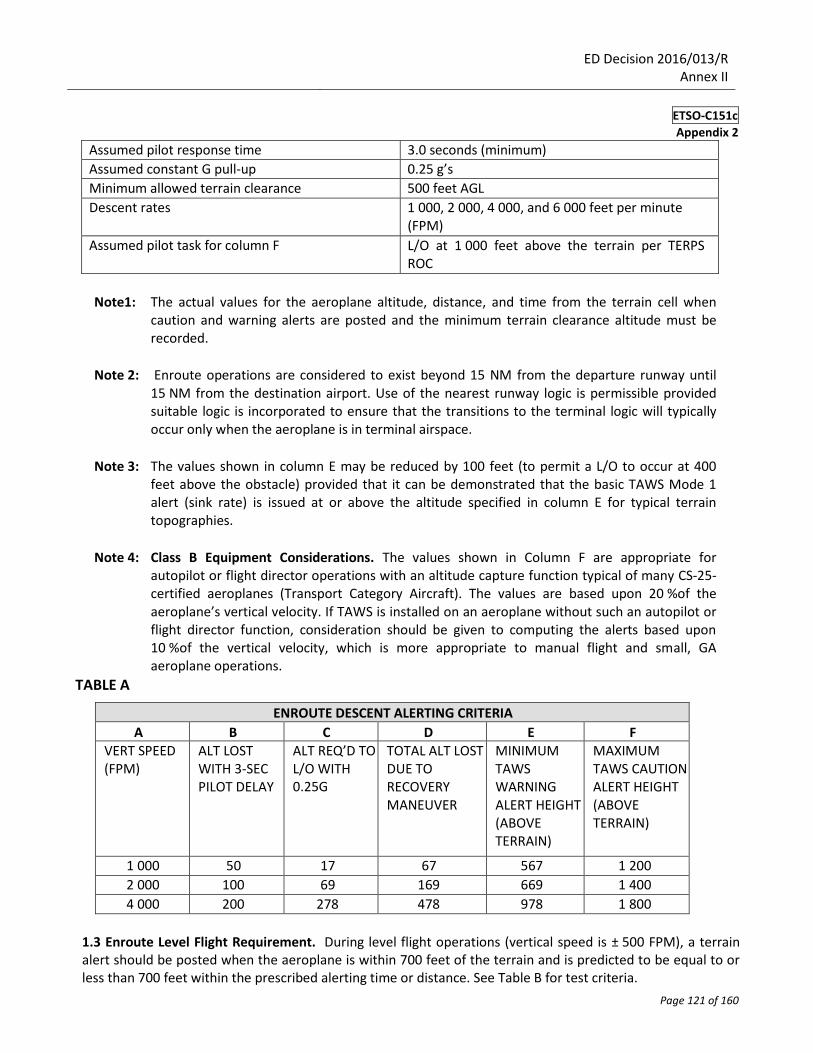
Assumed pilot response time 3.0 seconds (minimum)
Assumed constant G pull-up 0.25 g’s
Minimum allowed terrain clearance 500 feet AGL
Descent rates 1 000, 2 000, 4 000, and 6 000 feet per minute (FPM)
Assumed pilot task for column F L/O at 1 000 feet above the terrain per TERPS ROC
Note1: The actual values for the aeroplane altitude, distance, and time from the terrain cell when caution and warning alerts are posted and the minimum terrain clearance altitude must be recorded.
Note 2: Enroute operations are considered to exist beyond 15 NM from the departure runway until
15 NM from the destination airport. Use of the nearest runway logic is permissible provided suitable logic is incorporated to ensure that the transitions to the terminal logic will typically occur only when the aeroplane is in terminal airspace.
Note 3: The values shown in column E may be reduced by 100 feet (to permit a L/O to occur at 400
feet above the obstacle) provided that it can be demonstrated that the basic TAWS Mode 1 alert (sink rate) is issued at or above the altitude specified in column E for typical terrain topographies.
Note 4: Class B Equipment Considerations. The values shown in Column F are appropriate for
autopilot or flight director operations with an altitude capture function typical of many CS-25-certified aeroplanes (Transport Category Aircraft). The values are based upon 20 %of the aeroplane’s vertical velocity. If TAWS is installed on an aeroplane without such an autopilot or flight director function, consideration should be given to computing the alerts based upon 10 %of the vertical velocity, which is more appropriate to manual flight and small, GA aeroplane operations.
TABLE A
ENROUTE DESCENT ALERTING CRITERIA
A B C D E F VERT SPEED (FPM)
ALT LOST WITH 3-SEC PILOT DELAY
ALT REQ’D TO L/O WITH 0.25G
TOTAL ALT LOST DUE TO RECOVERY MANEUVER
MINIMUM TAWS WARNING ALERT HEIGHT (ABOVE TERRAIN)
MAXIMUM TAWS CAUTION ALERT HEIGHT (ABOVE TERRAIN)
1 000 50 17 67 567 1 200
2 000 100 69 169 669 1 400
4 000 200 278 478 978 1 800
1.3 Enroute Level Flight Requirement. During level flight operations (vertical speed is ± 500 FPM), a terrain alert should be posted when the aeroplane is within 700 feet of the terrain and is predicted to be equal to or less than 700 feet within the prescribed alerting time or distance. See Table B for test criteria.
ED Decision 2016/013/R Annex II
ETSO-C151c
Appendix 2
Page 122 of 160
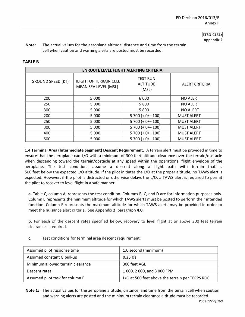
Note: The actual values for the aeroplane altitude, distance and time from the terrain cell when caution and warning alerts are posted must be recorded.
TABLE B
ENROUTE LEVEL FLIGHT ALERTING CRITERIA
GROUND SPEED (KT)
HEIGHT OF TERRAIN CELL MEAN SEA LEVEL (MSL)
TEST RUN ALTITUDE
(MSL)
ALERT CRITERIA
200 5 000 6 000 NO ALERT
250 5 000 5 800 NO ALERT
300 5 000 5 800 NO ALERT
200 5 000 5 700 (+ 0/– 100) MUST ALERT
250 5 000 5 700 (+ 0/– 100) MUST ALERT
300 5 000 5 700 (+ 0/– 100) MUST ALERT
400 5 000 5 700 (+ 0/– 100) MUST ALERT
500 5 000 5 700 (+ 0/– 100) MUST ALERT
1.4 Terminal Area (Intermediate Segment) Descent Requirement. A terrain alert must be provided in time to ensure that the aeroplane can L/O with a minimum of 300 feet altitude clearance over the terrain/obstacle when descending toward the terrain/obstacle at any speed within the operational flight envelope of the aeroplane. The test conditions assume a descent along a flight path with terrain that is 500 feet below the expected L/O altitude. If the pilot initiates the L/O at the proper altitude, no TAWS alert is expected. However, if the pilot is distracted or otherwise delays the L/O, a TAWS alert is required to permit the pilot to recover to level flight in a safe manner.
a. Table C, column A, represents the test condition. Columns B, C, and D are for information purposes only. Column E represents the minimum altitude for which TAWS alerts must be posted to perform their intended function. Column F represents the maximum altitude for which TAWS alerts may be provided in order to meet the nuisance alert criteria. See Appendix 2, paragraph 4.0.
b. For each of the descent rates specified below, recovery to level flight at or above 300 feet terrain clearance is required.
c. Test conditions for terminal area descent requirement:
Assumed pilot response time 1.0 second (minimum)
Assumed constant G pull-up 0.25 g’s
Minimum allowed terrain clearance 300 feet AGL
Descent rates 1 000, 2 000, and 3 000 FPM
Assumed pilot task for column F L/O at 500 feet above the terrain per TERPS ROC
Note 1: The actual values for the aeroplane altitude, distance, and time from the terrain cell when caution and warning alerts are posted and the minimum terrain clearance altitude must be recorded.
ED Decision 2016/013/R Annex II
ETSO-C151c
Appendix 2
Page 123 of 160
Note 2: For Class B Equipment Considerations. The values shown in Column F are appropriate for
autopilot or flight director operations with an altitude capture function typical of many CS-25-certificated aeroplanes (Transport Category Aircraft). The values are based upon 20 %of the aeroplanes vertical velocity. If TAWS is installed on an aeroplane without such an autopilot or flight director function, consideration should be given to computing the alerts upon 10 %of the vertical velocity, which is more appropriate to manual flight and small, GA aeroplane operations.
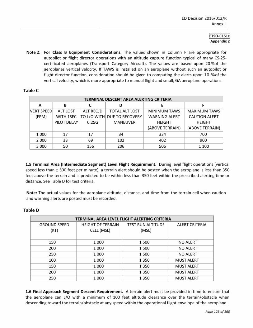
Table C
TERMINAL DESCENT AREA ALERTING CRITERIA
A B C D E F VERT SPEED
(FPM) ALT LOST
WITH 1SEC PILOT DELAY
ALT REQ’D TO L/O WITH
0.25G
TOTAL ALT LOST DUE TO RECOVERY
MANEUVER
MINIMUM TAWS WARNING ALERT
HEIGHT (ABOVE TERRAIN)
MAXIMUM TAWS CAUTION ALERT
HEIGHT (ABOVE TERRAIN)
1 000 17 17 34 334 700
2 000 33 69 102 402 900
3 000 50 156 206 506 1 100
1.5 Terminal Area (Intermediate Segment) Level Flight Requirement. During level flight operations (vertical speed less than ± 500 feet per minute), a terrain alert should be posted when the aeroplane is less than 350 feet above the terrain and is predicted to be within less than 350 feet within the prescribed alerting time or distance. See Table D for test criteria.
Note: The actual values for the aeroplane altitude, distance, and time from the terrain cell when caution and warning alerts are posted must be recorded.
Table D
TERMINAL AREA LEVEL FLIGHT ALERTING CRITERIA
GROUND SPEED (KT)
HEIGHT OF TERRAIN CELL (MSL)
TEST RUN ALTITUDE (MSL)
ALERT CRITERIA
150 1 000 1 500 NO ALERT
200 1 000 1 500 NO ALERT
250 1 000 1 500 NO ALERT
100 1 000 1 350 MUST ALERT
150 1 000 1 350 MUST ALERT
200 1 000 1 350 MUST ALERT
250 1 000 1 350 MUST ALERT
1.6 Final Approach Segment Descent Requirement. A terrain alert must be provided in time to ensure that the aeroplane can L/O with a minimum of 100 feet altitude clearance over the terrain/obstacle when descending toward the terrain/obstacle at any speed within the operational flight envelope of the aeroplane.
ED Decision 2016/013/R Annex II
ETSO-C151c
Appendix 2
Page 124 of 160
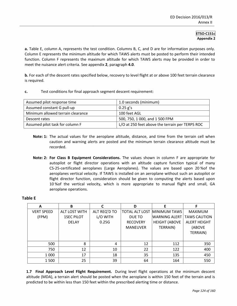
a. Table E, column A, represents the test condition. Columns B, C, and D are for information purposes only. Column E represents the minimum altitude for which TAWS alerts must be posted to perform their intended function. Column F represents the maximum altitude for which TAWS alerts may be provided in order to meet the nuisance alert criteria. See appendix 2, paragraph 4.0.
b. For each of the descent rates specified below, recovery to level flight at or above 100 feet terrain clearance is required.
c. Test conditions for final approach segment descent requirement:
Assumed pilot response time 1.0 seconds (minimum)
Assumed constant G pull-up 0.25 g’s
Minimum allowed terrain clearance 100 feet AGL
Descent rates 500, 750, 1 000, and 1 500 FPM
Assumed pilot task for column F L/O at 250 feet above the terrain per TERPS ROC
Note: 1: The actual values for the aeroplane altitude, distance, and time from the terrain cell when caution and warning alerts are posted and the minimum terrain clearance altitude must be recorded.
Note: 2: For Class B Equipment Considerations. The values shown in column F are appropriate for
autopilot or flight director operations with an altitude capture function typical of many CS-25-certificated aeroplanes (Large Aeroplanes). The values are based upon 20 %of the aeroplanes vertical velocity. If TAWS is installed on an aeroplane without such an autopilot or flight director function, consideration should be given to computing the alerts based upon 10 %of the vertical velocity, which is more appropriate to manual flight and small, GA aeroplane operations.
Table E
A B C D E F
VERT SPEED (FPM)
ALT LOST WITH 1SEC PILOT
DELAY
ALT REQ’D TO L/O WITH
0.25G
TOTAL ALT LOST DUE TO
RECOVERY MANEUVER
MINIMUM TAWS WARNING ALERT HEIGHT (ABOVE
TERRAIN)
MAXIMUM TAWS CAUTION ALERT HEIGHT
(ABOVE TERRAIN)
500 8 4 12 112 350
750 12 10 22 122 400
1 000 17 18 35 135 450
1 500 25 39 64 164 550
1.7 Final Approach Level Flight Requirement. During level flight operations at the minimum descent altitude (MDA), a terrain alert should be posted when the aeroplane is within 150 feet of the terrain and is predicted to be within less than 150 feet within the prescribed alerting time or distance.
ED Decision 2016/013/R Annex II
ETSO-C151c
Appendix 2
Page 125 of 160
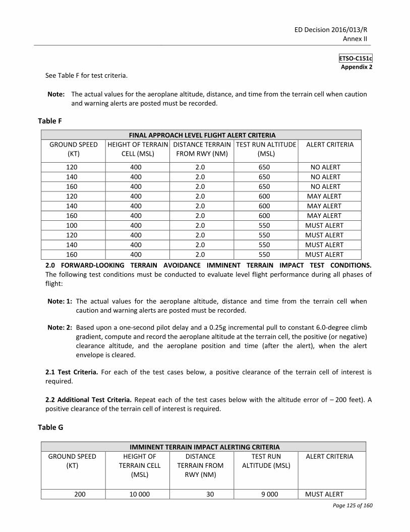
See Table F for test criteria.
Note: The actual values for the aeroplane altitude, distance, and time from the terrain cell when caution
and warning alerts are posted must be recorded.
Table F
FINAL APPROACH LEVEL FLIGHT ALERT CRITERIA
GROUND SPEED (KT)
HEIGHT OF TERRAIN CELL (MSL)
DISTANCE TERRAIN FROM RWY (NM)
TEST RUN ALTITUDE (MSL)
ALERT CRITERIA
120 400 2.0 650 NO ALERT
140 400 2.0 650 NO ALERT
160 400 2.0 650 NO ALERT
120 400 2.0 600 MAY ALERT
140 400 2.0 600 MAY ALERT
160 400 2.0 600 MAY ALERT
100 400 2.0 550 MUST ALERT
120 400 2.0 550 MUST ALERT
140 400 2.0 550 MUST ALERT
160 400 2.0 550 MUST ALERT
2.0 FORWARD-LOOKING TERRAIN AVOIDANCE IMMINENT TERRAIN IMPACT TEST CONDITIONS. The following test conditions must be conducted to evaluate level flight performance during all phases of flight:
Note: 1: The actual values for the aeroplane altitude, distance and time from the terrain cell when caution and warning alerts are posted must be recorded.
Note: 2: Based upon a one-second pilot delay and a 0.25g incremental pull to constant 6.0-degree climb
gradient, compute and record the aeroplane altitude at the terrain cell, the positive (or negative) clearance altitude, and the aeroplane position and time (after the alert), when the alert envelope is cleared.
2.1 Test Criteria. For each of the test cases below, a positive clearance of the terrain cell of interest is required.
2.2 Additional Test Criteria. Repeat each of the test cases below with the altitude error of – 200 feet). A positive clearance of the terrain cell of interest is required.
Table G
IMMINENT TERRAIN IMPACT ALERTING CRITERIA
GROUND SPEED (KT)
HEIGHT OF TERRAIN CELL
(MSL)
DISTANCE TERRAIN FROM
RWY (NM)
TEST RUN ALTITUDE (MSL)
ALERT CRITERIA
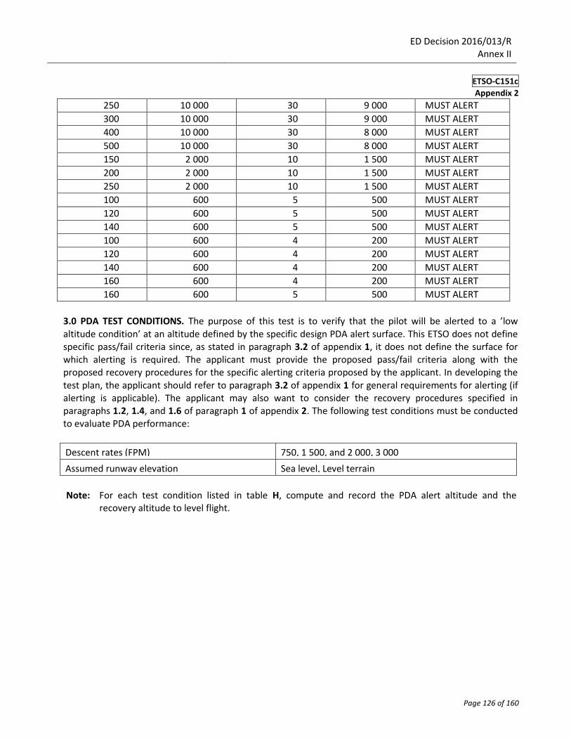
200 10 000 30 9 000 MUST ALERT
ED Decision 2016/013/R Annex II
ETSO-C151c
Appendix 2
Page 126 of 160
250 10 000 30 9 000 MUST ALERT
300 10 000 30 9 000 MUST ALERT
400 10 000 30 8 000 MUST ALERT
500 10 000 30 8 000 MUST ALERT
150 2 000 10 1 500 MUST ALERT
200 2 000 10 1 500 MUST ALERT
250 2 000 10 1 500 MUST ALERT
100 600 5 500 MUST ALERT
120 600 5 500 MUST ALERT
140 600 5 500 MUST ALERT
100 600 4 200 MUST ALERT
120 600 4 200 MUST ALERT
140 600 4 200 MUST ALERT
160 600 4 200 MUST ALERT
160 600 5 500 MUST ALERT
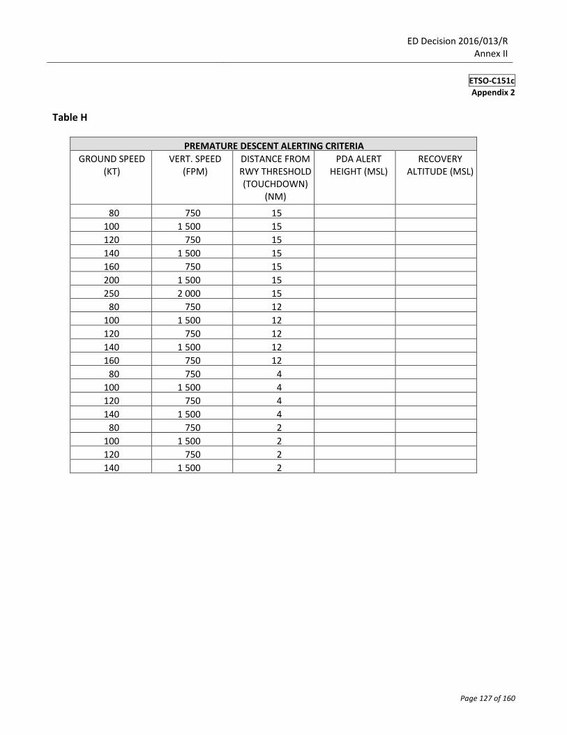
3.0 PDA TEST CONDITIONS. The purpose of this test is to verify that the pilot will be alerted to a ’low
altitude condition’ at an altitude defined by the specific design PDA alert surface. This ETSO does not define specific pass/fail criteria since, as stated in paragraph 3.2 of appendix 1, it does not define the surface for which alerting is required. The applicant must provide the proposed pass/fail criteria along with the proposed recovery procedures for the specific alerting criteria proposed by the applicant. In developing the test plan, the applicant should refer to paragraph 3.2 of appendix 1 for general requirements for alerting (if alerting is applicable). The applicant may also want to consider the recovery procedures specified in paragraphs 1.2, 1.4, and 1.6 of paragraph 1 of appendix 2. The following test conditions must be conducted to evaluate PDA performance:
Descent rates (FPM) 750, 1 500, and 2 000, 3 000
Assumed runway elevation Sea level, Level terrain
Note: For each test condition listed in table H, compute and record the PDA alert altitude and the recovery altitude to level flight.
ED Decision 2016/013/R Annex II
ETSO-C151c
Appendix 2
Page 127 of 160
Table H
PREMATURE DESCENT ALERTING CRITERIA
GROUND SPEED (KT)
VERT. SPEED (FPM)
DISTANCE FROM RWY THRESHOLD (TOUCHDOWN)
(NM)
PDA ALERT HEIGHT (MSL)
RECOVERY ALTITUDE (MSL)
80 750 15
100 1 500 15
120 750 15
140 1 500 15
160 750 15
200 1 500 15
250 2 000 15
80 750 12
100 1 500 12
120 750 12
140 1 500 12
160 750 12
80 750 4
100 1 500 4
120 750 4
140 1 500 4
80 750 2
100 1 500 2
120 750 2
140 1 500 2
ED Decision 2016/013/R Annex II
ETSO-C151c
Appendix 2
Page 128 of 160
4.0 NUISANCE ALERT TEST CONDITIONS — GENERAL. The following test conditions must be conducted to evaluate TAWS performance during all phases of flight. The following general criteria apply:
4.1 4 000 FPM. Descent must be possible at 4 000 FPM in the enroute airspace and pilots must be able to L/O 1 000 feet above the terrain using a normal L/O procedure (leading by 20 %of the vertical speed) without a caution or warning alert. See Table A.
4.2 2 000 FPM. Descent must be possible at 2 000 FPM in the terminal area and pilots must be able to L/O 500 feet above the terrain using the normal L/O procedure described in paragraph 4.1 above, without a caution or warning alert. See Table C.
4.3 1 000 FPM. Descent must be possible at 1 000 FPM in the final approach segment and pilots must be able to L/O at the MDA using the normal L/O procedure described in paragraph 4.1 above, without a caution or warning alert. See Table E.
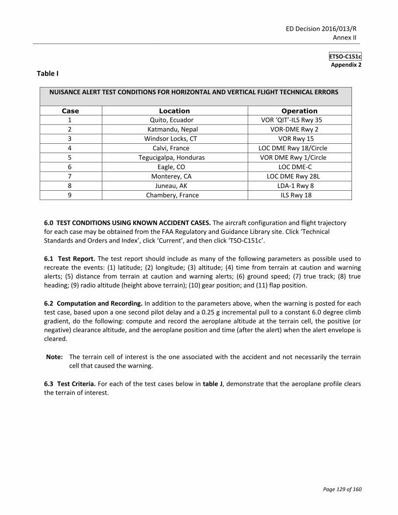
5.0 NUISANCE TEST CONDITIONS FOR HORIZONTAL AND VERTICAL FLIGHT TECHNICAL ERRORS. It must be shown by analysis, simulation, or flight testing, that the system will not produce nuisance alerts when the aeroplane is conducting normal flight operations in accordance with published instrument approach procedures. This assumes the normal range in variation of input parameters.
5.1 Test Cases. At a minimum, the following cases listed in Table I must be tested twice: one set of runs conducted with no lateral or vertical errors while another set is conducted with both lateral and vertical flight technical errors (FTE). Certain conditions must be simulated, such as: a lateral FTE of 0.3 NM and a vertical FTE of – 100 feet (such as when the aircraft is closer to terrain) up to the final approach fix (FAF), as well as a lateral FTE of 0.3 NM and a vertical FTE of – 50 feet from the FAF to the missed approach point (MAP). For all listed VHF omni- directional range navigation system (VOR), VOR/distance measuring equipment (DME) and localizer-based approaches, from the FAF to the MAP, the aeroplane descends at 1 000 FPM until reaching either MDA (run #1) or MDA – 50 feet (run #2). The aeroplane then levels off and flies level until reaching the MAP. Localizer updating of lateral position errors (if provided) may be simulated.
ED Decision 2016/013/R Annex II
ETSO-C151c
Appendix 2
Page 129 of 160
Table I
NUISANCE ALERT TEST CONDITIONS FOR HORIZONTAL AND VERTICAL FLIGHT TECHNICAL ERRORS
Case Location Operation
1 Quito, Ecuador VOR ‘QIT’-ILS Rwy 35
2 Katmandu, Nepal VOR-DME Rwy 2
3 Windsor Locks, CT VOR Rwy 15
4 Calvi, France LOC DME Rwy 18/Circle
5 Tegucigalpa, Honduras VOR DME Rwy 1/Circle
6 Eagle, CO LOC DME-C
7 Monterey, CA LOC DME Rwy 28L
8 Juneau, AK LDA-1 Rwy 8
9 Chambery, France ILS Rwy 18
6.0 TEST CONDITIONS USING KNOWN ACCIDENT CASES. The aircraft configuration and flight trajectory for each case may be obtained from the FAA Regulatory and Guidance Library site. Click ‘Technical Standards and Orders and Index’, click ‘Current’, and then click ‘TSO-C151c’.
6.1 Test Report. The test report should include as many of the following parameters as possible used to recreate the events: (1) latitude; (2) longitude; (3) altitude; (4) time from terrain at caution and warning alerts; (5) distance from terrain at caution and warning alerts; (6) ground speed; (7) true track; (8) true heading; (9) radio altitude (height above terrain); (10) gear position; and (11) flap position.
6.2 Computation and Recording. In addition to the parameters above, when the warning is posted for each test case, based upon a one second pilot delay and a 0.25 g incremental pull to a constant 6.0 degree climb gradient, do the following: compute and record the aeroplane altitude at the terrain cell, the positive (or negative) clearance altitude, and the aeroplane position and time (after the alert) when the alert envelope is cleared.
Note: The terrain cell of interest is the one associated with the accident and not necessarily the terrain
cell that caused the warning.
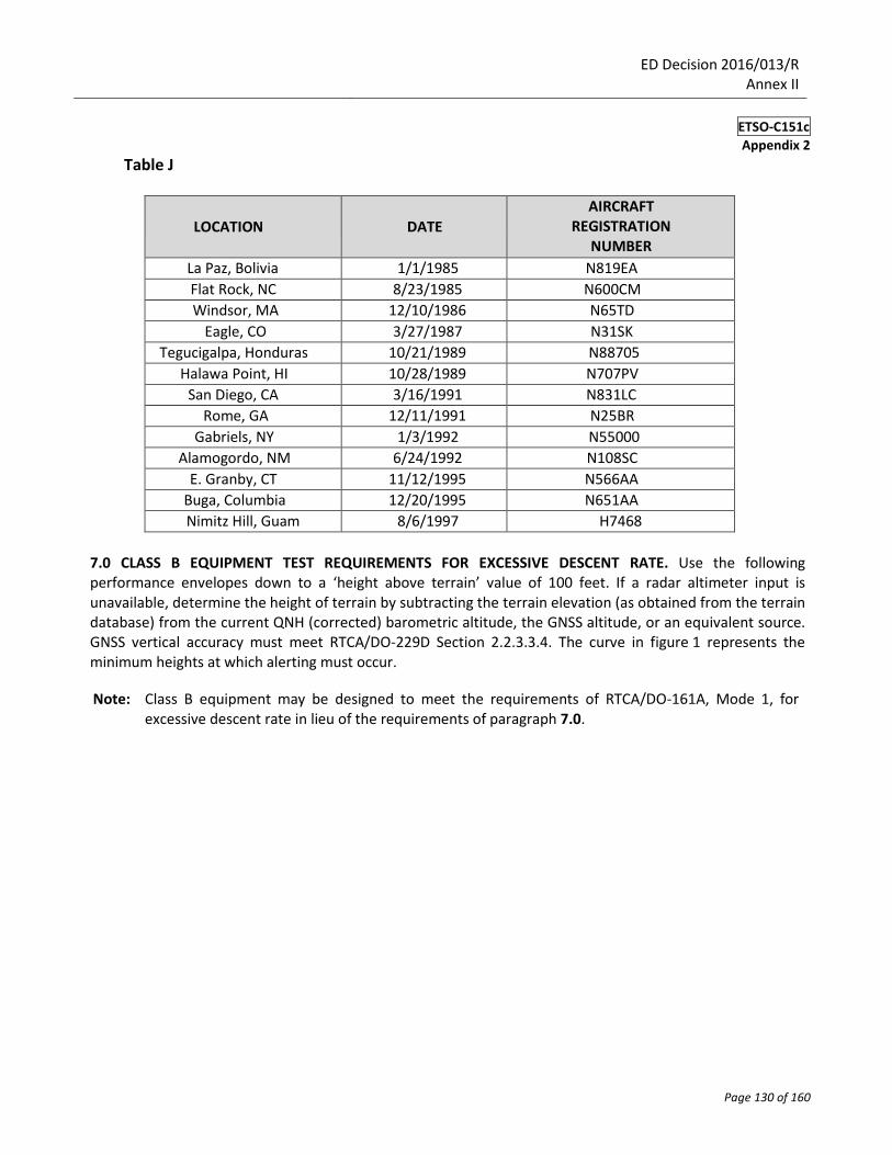
6.3 Test Criteria. For each of the test cases below in table J, demonstrate that the aeroplane profile clears the terrain of interest.
ED Decision 2016/013/R Annex II
ETSO-C151c
Appendix 2
Page 130 of 160
Table J
LOCATION
DATE
AIRCRAFT REGISTRATION
NUMBER
La Paz, Bolivia 1/1/1985 N819EA
Flat Rock, NC 8/23/1985 N600CM
Windsor, MA 12/10/1986 N65TD
Eagle, CO 3/27/1987 N31SK
Tegucigalpa, Honduras 10/21/1989 N88705
Halawa Point, HI 10/28/1989 N707PV
San Diego, CA 3/16/1991 N831LC
Rome, GA 12/11/1991 N25BR
Gabriels, NY 1/3/1992 N55000
Alamogordo, NM 6/24/1992 N108SC
E. Granby, CT 11/12/1995 N566AA
Buga, Columbia 12/20/1995 N651AA
Nimitz Hill, Guam 8/6/1997 H7468
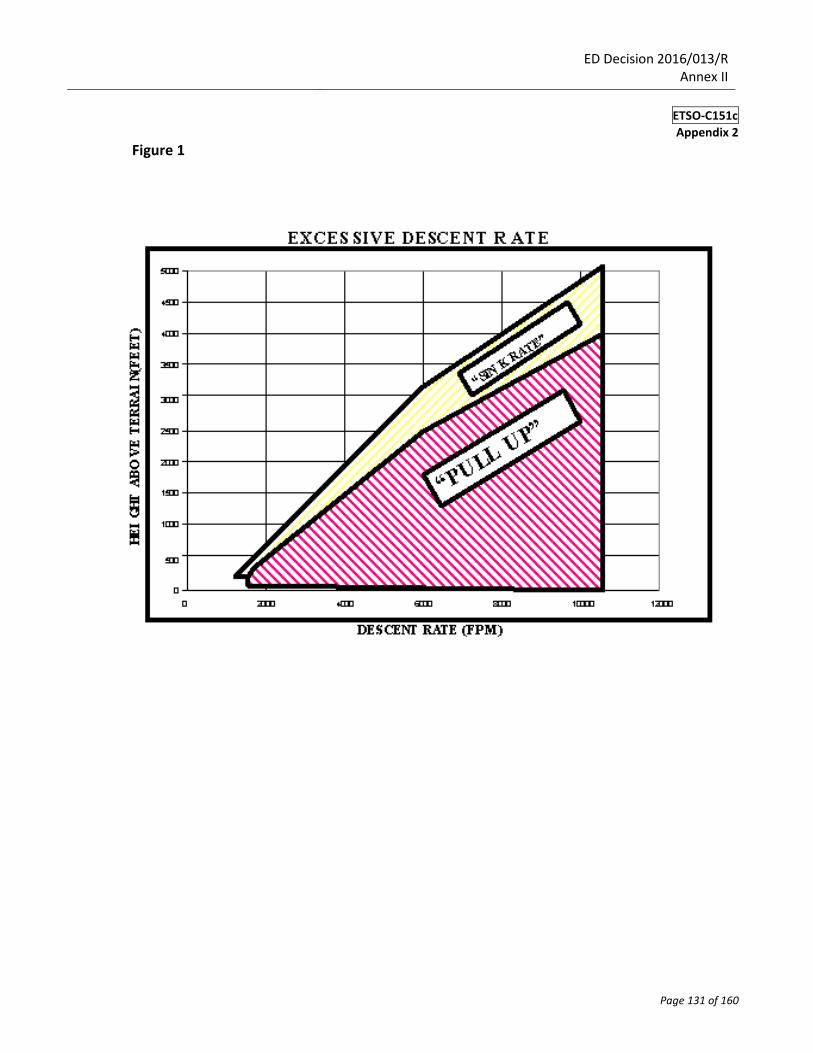
7.0 CLASS B EQUIPMENT TEST REQUIREMENTS FOR EXCESSIVE DESCENT RATE. Use the following performance envelopes down to a ‘height above terrain’ value of 100 feet. If a radar altimeter input is unavailable, determine the height of terrain by subtracting the terrain elevation (as obtained from the terrain database) from the current QNH (corrected) barometric altitude, the GNSS altitude, or an equivalent source. GNSS vertical accuracy must meet RTCA/DO-229D Section 2.2.3.3.4. The curve in figure 1 represents the minimum heights at which alerting must occur.
Note: Class B equipment may be designed to meet the requirements of RTCA/DO-161A, Mode 1, for
excessive descent rate in lieu of the requirements of paragraph 7.0.
ED Decision 2016/013/R Annex II
ETSO-C151c
Appendix 2
Page 131 of 160
Figure 1
ED Decision 2016/013/R Annex II
ETSO-C151c
Appendix 2
Page 132 of 160
8.0 CLASS B EQUIPMENT TEST REQUIREMENTS FOR NEGATIVE CLIMB RATE OR ALTITUDE LOSS AFTER TAKEOFF. Use the existing performance envelopes specified in RTCA/DO-161A based upon a ‘height above runway’ using barometric altitude, GNSS altitude, or equivalent, and runway elevation in lieu of radio altimeter inputs, if radio altimeter inputs are unavailable.
9.0 ALTITUDE CALLOUT TEST REQUIREMENTS
9.1 CLASS A EQUIPMENT ALTITUDE CALLOUT TEST REQUIREMENTS. With the landing gear in landing configuration test for approach to an airport with a 1 500 FPM descent rate. Ensure the TAWS provides a single aural callout of ‘Five Hundred’ or equivalent within one second of the aircraft descending through 500 feet above terrain or the runway threshold elevation (when comparing the aircraft’s barometric or geometric altitude against the database runway elevation).
9.2 CLASS B EQUIPMENT ALTITUDE CALLOUT TEST REQUIREMENTS. Instead of using height of terrain as determined by a radio altimeter, determine height above runway by subtracting the runway elevation (from the airport database) from the current barometric altitude, GNSS altitude, or equivalent, if a radio altimeter input is unavailable. When the height above the runway value first reaches 500 feet, a single voice callout (‘Five Hundred’) or equivalent must be provided.

ED Decision 2016/013/R Annex II
ETSO-C151c
Appendix 3
Page 133 of 160
APPENDIX 3
MINIMUM PERFORMANCE STANDARD (MPS) FOR A TERRAIN AWARENESS AND WARNING SYSTEM FOR CLASS C
1.0 INTRODUCTION
1.1 This Appendix describes modifications to this ETSO for the GA category of aircraft that is not required to have TAWS equipment installed. Class C equipment is intended for small GA aeroplanes that are not required to install Class B equipment.
1.2 This Appendix contains only modifications to existing requirements in this ETSO. It is intended that Class C meet all Class B requirements that are not modified or addressed here. The paragraph numbers below relate directly to the paragraphs in Appendices 1 and 2.
2.0 Class C TAWS equipment must meet all of the requirements of a Class B TAWS with the modifications described herein. If the equipment is designed only to function as Class C, per these modifications, it should be appropriately marked as Class C so that it can be uniquely distinguished from the Class A and Class B TAWS required by the EU Regulation on Air Operations.
MODIFICATIONS TO APPENDIX 1 FOR CLASS C TAWS.
Minimum Performance Standards, MPS
1.1 Phase of Flight Definitions. For Appendix 3, the terms ‘takeoff’, ‘cruise’, and ‘landing’ are used instead of ‘departure’, ‘enroute’, and ‘approach’ because they are more suitable to the GA environment.
— Takeoff—positive ROC, inside traffic area, distance to nearest runway threshold is increasing, and
aeroplane is below 1 000 feet.
— Cruise — anytime the aeroplane is outside the airport traffic control area.
— Landing — inside traffic area and distance to nearest runway threshold is decreasing, and aeroplane is
below 1 000 feet.
1.2 Altitude Accuracy and Display. A means must be provided to compute an actual MSL aircraft altitude value that is immune to temperature errors and manual correction mis-sets that would otherwise prevent the TAWS from performing its intended function. This type of altitude is derived primarily from geometric sources such as GPS, and referenced to MSL typically via a database correction. If the TAWS includes a terrain display, this reference altitude value used for the TAWS alerts should also be indicated to the pilot on the display. The altitude value should be labelled according to AC 20-163, Displaying Geometric Altitude Relative to Mean Sea Level, which recommends ‘GSL’. 1.3 (f)(3) System Function and Overview. This data is pilot selectable for both ‘altitude’ and ‘inhibit’.
ED Decision 2016/013/R Annex II
ETSO-C151c
Appendix 3
Page 134 of 160
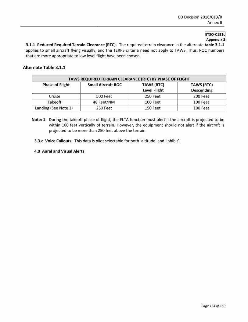
3.1.1 Reduced Required Terrain Clearance (RTC). The required terrain clearance in the alternate table 3.1.1 applies to small aircraft flying visually, and the TERPS criteria need not apply to TAWS. Thus, ROC numbers that are more appropriate to low level flight have been chosen.
Alternate Table 3.1.1
TAWS REQUIRED TERRAIN CLEARANCE (RTC) BY PHASE OF FLIGHT
Phase of Flight Small Aircraft ROC TAWS (RTC) Level Flight
TAWS (RTC) Descending
Cruise 500 Feet 250 Feet 200 Feet
Takeoff 48 Feet/NM 100 Feet 100 Feet
Landing (See Note 1) 250 Feet 150 Feet 100 Feet
Note: 1: During the takeoff phase of flight, the FLTA function must alert if the aircraft is projected to be within 100 feet vertically of terrain. However, the equipment should not alert if the aircraft is projected to be more than 250 feet above the terrain.
3.3.c Voice Callouts. This data is pilot selectable for both ‘altitude’ and ‘inhibit’.
4.0 Aural and Visual Alerts
ED Decision 2016/013/R Annex II
ETSO-C151c
Appendix 3
Page 135 of 160
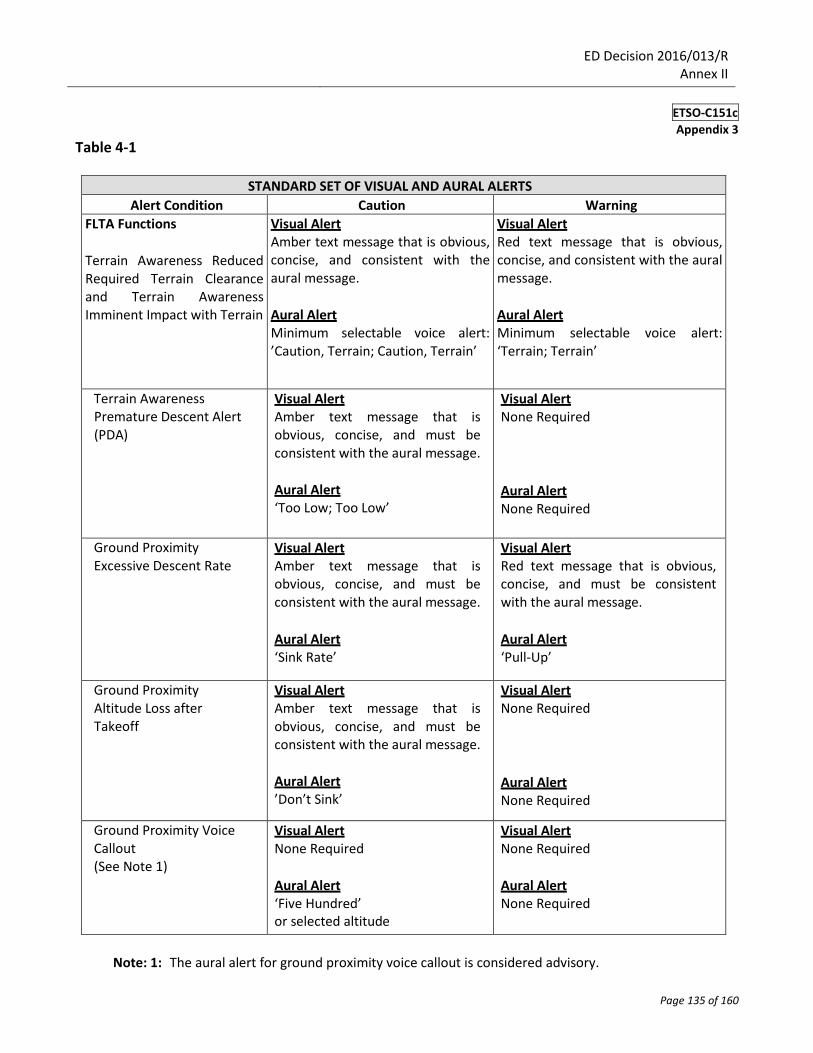
Table 4-1
STANDARD SET OF VISUAL AND AURAL ALERTS
Alert Condition Caution Warning
FLTA Functions
Terrain Awareness Reduced Required Terrain Clearance and Terrain Awareness Imminent Impact with Terrain
Visual Alert Amber text message that is obvious, concise, and consistent with the aural message.
Aural Alert Minimum selectable voice alert: ’Caution, Terrain; Caution, Terrain’
Visual Alert Red text message that is obvious, concise, and consistent with the aural message.
Aural Alert Minimum selectable voice alert: ‘Terrain; Terrain’
Terrain Awareness Premature Descent Alert (PDA)
Visual Alert Amber text message that is obvious, concise, and must be consistent with the aural message.
Aural Alert ‘Too Low; Too Low’
Visual Alert None Required Aural Alert None Required
Ground Proximity Excessive Descent Rate
Visual Alert Amber text message that is obvious, concise, and must be consistent with the aural message.
Aural Alert ‘Sink Rate’
Visual Alert Red text message that is obvious, concise, and must be consistent with the aural message.
Aural Alert ‘Pull-Up’
Ground Proximity Altitude Loss after Takeoff
Visual Alert Amber text message that is obvious, concise, and must be consistent with the aural message.
Aural Alert ’Don’t Sink’
Visual Alert None Required Aural Alert None Required
Ground Proximity Voice Callout (See Note 1)
Visual Alert None Required
Aural Alert ‘Five Hundred’ or selected altitude
Visual Alert None Required
Aural Alert None Required
Note: 1: The aural alert for ground proximity voice callout is considered advisory.
ED Decision 2016/013/R Annex II
ETSO-C151c
Appendix 3
Page 136 of 160
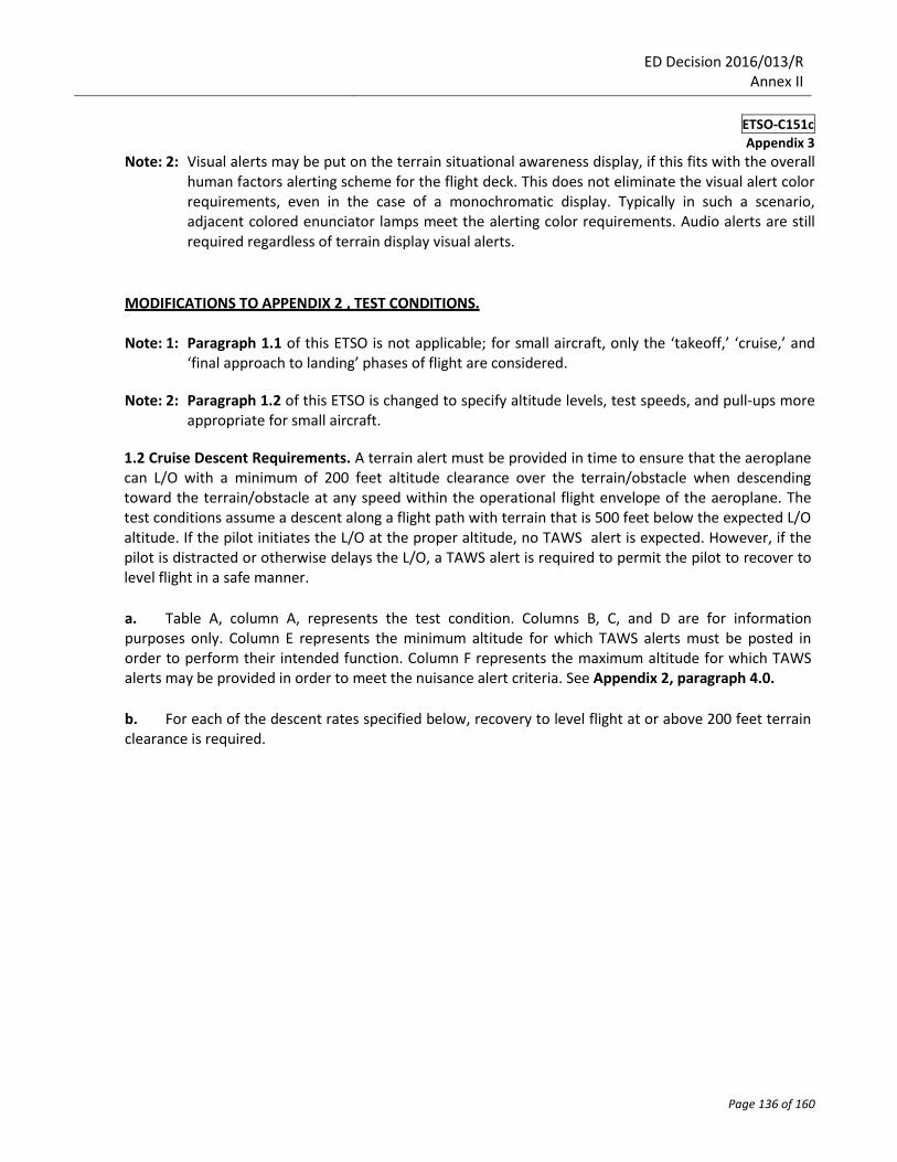
Note: 2: Visual alerts may be put on the terrain situational awareness display, if this fits with the overall human factors alerting scheme for the flight deck. This does not eliminate the visual alert color requirements, even in the case of a monochromatic display. Typically in such a scenario, adjacent colored enunciator lamps meet the alerting color requirements. Audio alerts are still required regardless of terrain display visual alerts.
MODIFICATIONS TO APPENDIX 2 , TEST CONDITIONS.
Note: 1: Paragraph 1.1 of this ETSO is not applicable; for small aircraft, only the ‘takeoff,’ ‘cruise,’ and ‘final approach to landing’ phases of flight are considered.
Note: 2: Paragraph 1.2 of this ETSO is changed to specify altitude levels, test speeds, and pull-ups more
appropriate for small aircraft. 1.2 Cruise Descent Requirements. A terrain alert must be provided in time to ensure that the aeroplane can L/O with a minimum of 200 feet altitude clearance over the terrain/obstacle when descending toward the terrain/obstacle at any speed within the operational flight envelope of the aeroplane. The test conditions assume a descent along a flight path with terrain that is 500 feet below the expected L/O altitude. If the pilot initiates the L/O at the proper altitude, no TAWS alert is expected. However, if the pilot is distracted or otherwise delays the L/O, a TAWS alert is required to permit the pilot to recover to level flight in a safe manner.
a. Table A, column A, represents the test condition. Columns B, C, and D are for information purposes only. Column E represents the minimum altitude for which TAWS alerts must be posted in order to perform their intended function. Column F represents the maximum altitude for which TAWS alerts may be provided in order to meet the nuisance alert criteria. See Appendix 2, paragraph 4.0.
b. For each of the descent rates specified below, recovery to level flight at or above 200 feet terrain clearance is required.
ED Decision 2016/013/R Annex II
ETSO-C151c
Appendix 3
Page 137 of 160
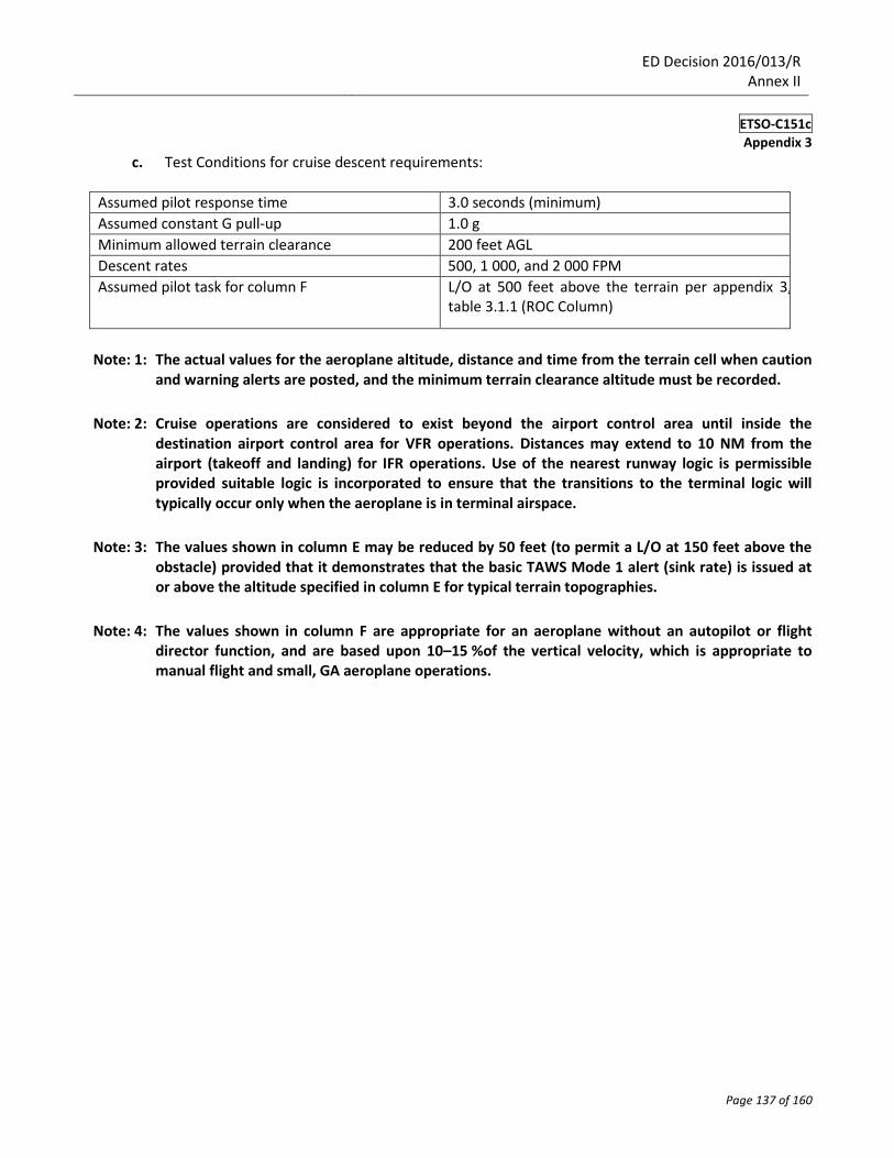
c. Test Conditions for cruise descent requirements:
Assumed pilot response time 3.0 seconds (minimum)
Assumed constant G pull-up 1.0 g
Minimum allowed terrain clearance 200 feet AGL
Descent rates 500, 1 000, and 2 000 FPM
Assumed pilot task for column F L/O at 500 feet above the terrain per appendix 3, table 3.1.1 (ROC Column)
Note: 1: The actual values for the aeroplane altitude, distance and time from the terrain cell when caution and warning alerts are posted, and the minimum terrain clearance altitude must be recorded.
Note: 2: Cruise operations are considered to exist beyond the airport control area until inside the destination airport control area for VFR operations. Distances may extend to 10 NM from the airport (takeoff and landing) for IFR operations. Use of the nearest runway logic is permissible provided suitable logic is incorporated to ensure that the transitions to the terminal logic will typically occur only when the aeroplane is in terminal airspace.
Note: 3: The values shown in column E may be reduced by 50 feet (to permit a L/O at 150 feet above the obstacle) provided that it demonstrates that the basic TAWS Mode 1 alert (sink rate) is issued at or above the altitude specified in column E for typical terrain topographies.
Note: 4: The values shown in column F are appropriate for an aeroplane without an autopilot or flight director function, and are based upon 10–15 %of the vertical velocity, which is appropriate to manual flight and small, GA aeroplane operations.
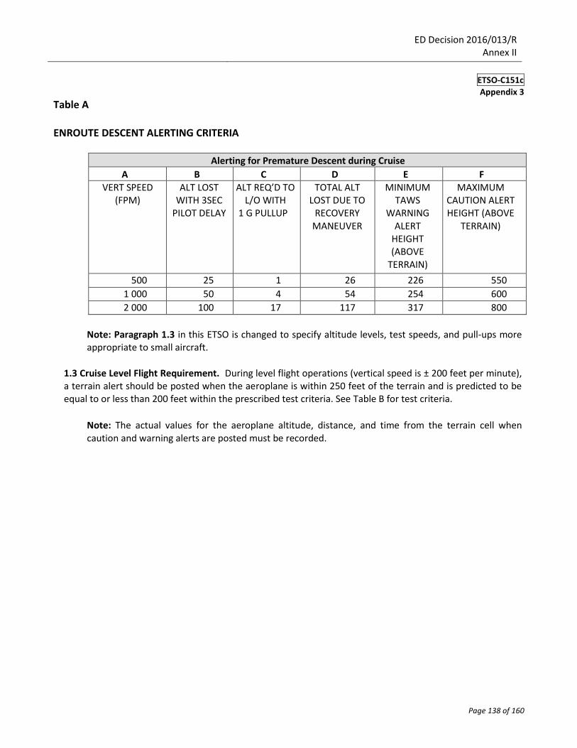
ED Decision 2016/013/R Annex II
ETSO-C151c
Appendix 3
Page 138 of 160
Table A ENROUTE DESCENT ALERTING CRITERIA
Alerting for Premature Descent during Cruise
A B C D E F VERT SPEED
(FPM) ALT LOST
WITH 3SEC PILOT DELAY
ALT REQ’D TO L/O WITH
1 G PULLUP
TOTAL ALT LOST DUE TO
RECOVERY MANEUVER
MINIMUM TAWS
WARNING ALERT
HEIGHT (ABOVE
TERRAIN)
MAXIMUM CAUTION ALERT HEIGHT (ABOVE
TERRAIN)
500 25 1 26 226 550
1 000 50 4 54 254 600
2 000 100 17 117 317 800
Note: Paragraph 1.3 in this ETSO is changed to specify altitude levels, test speeds, and pull-ups more appropriate to small aircraft.
1.3 Cruise Level Flight Requirement. During level flight operations (vertical speed is ± 200 feet per minute), a terrain alert should be posted when the aeroplane is within 250 feet of the terrain and is predicted to be equal to or less than 200 feet within the prescribed test criteria. See Table B for test criteria.
Note: The actual values for the aeroplane altitude, distance, and time from the terrain cell when caution and warning alerts are posted must be recorded.
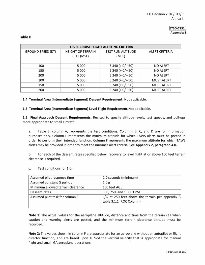
ED Decision 2016/013/R Annex II
ETSO-C151c
Appendix 3
Page 139 of 160
Table B
LEVEL CRUISE FLIGHT ALERTING CRITERIA GROUND SPEED (KT) HEIGHT OF TERRAIN
CELL (MSL) TEST RUN ALTITUDE
(MSL) ALERT CRITERIA
100 5 000 5 340 (+ 0/– 50) NO ALERT
150 5 000 5 340 (+ 0/– 50) NO ALERT
200 5 000 5 340 (+ 0/– 50) NO ALERT
100 5 000 5 240 (+ 0/– 50) MUST ALERT
150 5 000 5 240 (+ 0/– 50) MUST ALERT
200 5 000 5 240 (+ 0/– 50) MUST ALERT
1.4 Terminal Area (Intermediate Segment) Descent Requirement. Not applicable.
1.5 Terminal Area (Intermediate Segment) Level Flight Requirement.Not applicable.
1.6 Final Approach Descent Requirements. Revised to specify altitude levels, test speeds, and pull-ups more appropriate to small aircraft:
a. Table E, column A, represents the test conditions. Columns B, C, and D are for information purposes only. Column E represents the minimum altitude for which TAWS alerts must be posted in order to perform their intended function. Column F represents the maximum altitude for which TAWS alerts may be provided in order to meet the nuisance alert criteria. See Appendix 2, paragraph 4.0.
b. For each of the descent rates specified below, recovery to level flight at or above 100 feet terrain clearance is required.
c. Test conditions for 1.6:
Assumed pilot response time 1.0 seconds (minimum)
Assumed constant G pull-up 1.0 g
Minimum allowed terrain clearance 100 feet AGL
Descent rates 500, 750, and 1 000 FPM
Assumed pilot task for column F L/O at 250 feet above the terrain per appendix 3, table 3.1.1 (ROC Column)
Note 1: The actual values for the aeroplane altitude, distance and time from the terrain cell when caution and warning alerts are posted, and the minimum terrain clearance altitude must be recorded.
Note 2: The values shown in column F are appropriate for an aeroplane without an autopilot or flight director function, and are based upon 10 %of the vertical velocity that is appropriate for manual flight and small, GA aeroplane operations.
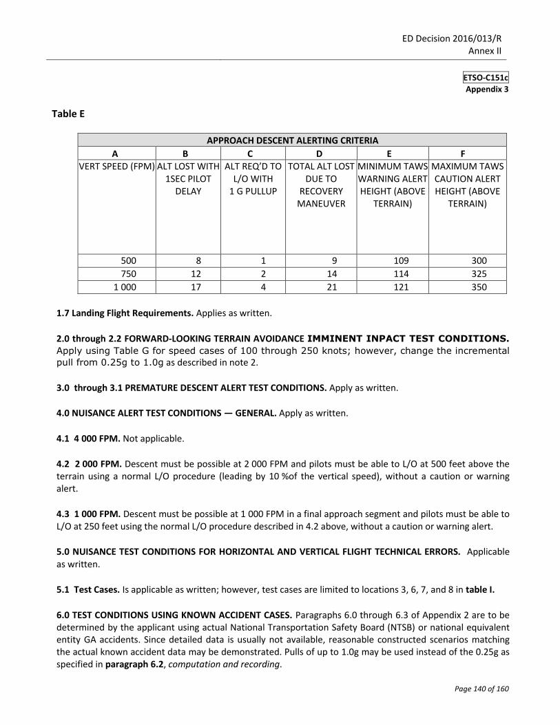
ED Decision 2016/013/R Annex II
ETSO-C151c
Appendix 3
Page 140 of 160
Table E
APPROACH DESCENT ALERTING CRITERIA
A B C D E F VERT SPEED (FPM) ALT LOST WITH
1SEC PILOT DELAY
ALT REQ’D TO L/O WITH
1 G PULLUP
TOTAL ALT LOST DUE TO
RECOVERY MANEUVER
MINIMUM TAWS WARNING ALERT HEIGHT (ABOVE
TERRAIN)
MAXIMUM TAWS CAUTION ALERT HEIGHT (ABOVE
TERRAIN)
500 8 1 9 109 300
750 12 2 14 114 325
1 000 17 4 21 121 350
1.7 Landing Flight Requirements. Applies as written.
2.0 through 2.2 FORWARD-LOOKING TERRAIN AVOIDANCE IMMINENT INPACT TEST CONDITIONS.
Apply using Table G for speed cases of 100 through 250 knots; however, change the incremental
pull from 0.25g to 1.0g as described in note 2.
3.0 through 3.1 PREMATURE DESCENT ALERT TEST CONDITIONS. Apply as written.
4.0 NUISANCE ALERT TEST CONDITIONS — GENERAL. Apply as written.
4.1 4 000 FPM. Not applicable.
4.2 2 000 FPM. Descent must be possible at 2 000 FPM and pilots must be able to L/O at 500 feet above the terrain using a normal L/O procedure (leading by 10 %of the vertical speed), without a caution or warning alert.
4.3 1 000 FPM. Descent must be possible at 1 000 FPM in a final approach segment and pilots must be able to L/O at 250 feet using the normal L/O procedure described in 4.2 above, without a caution or warning alert.
5.0 NUISANCE TEST CONDITIONS FOR HORIZONTAL AND VERTICAL FLIGHT TECHNICAL ERRORS. Applicable as written.
5.1 Test Cases. Is applicable as written; however, test cases are limited to locations 3, 6, 7, and 8 in table I.
6.0 TEST CONDITIONS USING KNOWN ACCIDENT CASES. Paragraphs 6.0 through 6.3 of Appendix 2 are to be determined by the applicant using actual National Transportation Safety Board (NTSB) or national equivalent entity GA accidents. Since detailed data is usually not available, reasonable constructed scenarios matching the actual known accident data may be demonstrated. Pulls of up to 1.0g may be used instead of the 0.25g as specified in paragraph 6.2, computation and recording.
ED Decision 2016/013/R Annex II
ETSO-C151c
Appendix 3
Page 141 of 160
7.0 CLASS C EQUIPMENT TEST REQUIREMENTS FOR EXCESSIVE DESCENT RATE. Apply Class B as written.
8.0 CLASS C EQUIPMENT TEST REQUIREMENTS FOR NEGATIVE CLIMB RATE OR ALTITUDE LOSS AFTER TAKEOFF. Apply Class B as written.
9.0 CLASS C EQUIPMENT TEST REQUIREMENTS FOR THE ALTITUDE CALLOUTS. Apply Class B as written.