etsi gr nfv-ifa 017 v2.1 · etsi 2 etsi gr nfv-ifa 017 v2.1.1 (2017-02) reference dgr/nfv-ifa017...
TRANSCRIPT
ETSI GR NFV-IFA 017 V2.1.1 (2017-02)
Network Functions Virtualisation (NFV) Release 2; Information Modeling;
UML Modeling Guidelines
Disclaimer
The present document has been produced and approved by the Network Functions Virtualisation (NFV) ETSI Industry Specification Group (ISG) and represents the views of those members who participated in this ISG.
It does not necessarily represent the views of the entire ETSI membership.
GROUP REPORT
ETSI
ETSI GR NFV-IFA 017 V2.1.1 (2017-02) 2
Reference DGR/NFV-IFA017
Keywords information model, NFV, UML
ETSI
650 Route des Lucioles F-06921 Sophia Antipolis Cedex - FRANCE
Tel.: +33 4 92 94 42 00 Fax: +33 4 93 65 47 16
Siret N° 348 623 562 00017 - NAF 742 C
Association à but non lucratif enregistrée à la Sous-Préfecture de Grasse (06) N° 7803/88
Important notice
The present document can be downloaded from: http://www.etsi.org/standards-search
The present document may be made available in electronic versions and/or in print. The content of any electronic and/or print versions of the present document shall not be modified without the prior written authorization of ETSI. In case of any
existing or perceived difference in contents between such versions and/or in print, the only prevailing document is the print of the Portable Document Format (PDF) version kept on a specific network drive within ETSI Secretariat.
Users of the present document should be aware that the document may be subject to revision or change of status. Information on the current status of this and other ETSI documents is available at
https://portal.etsi.org/TB/ETSIDeliverableStatus.aspx
If you find errors in the present document, please send your comment to one of the following services: https://portal.etsi.org/People/CommiteeSupportStaff.aspx
Copyright Notification
No part may be reproduced or utilized in any form or by any means, electronic or mechanical, including photocopying and microfilm except as authorized by written permission of ETSI.
The content of the PDF version shall not be modified without the written authorization of ETSI. The copyright and the foregoing restriction extend to reproduction in all media.
© European Telecommunications Standards Institute 2017.
All rights reserved.
DECTTM, PLUGTESTSTM, UMTSTM and the ETSI logo are Trade Marks of ETSI registered for the benefit of its Members. 3GPPTM and LTE™ are Trade Marks of ETSI registered for the benefit of its Members and
of the 3GPP Organizational Partners. GSM® and the GSM logo are Trade Marks registered and owned by the GSM Association.
ETSI
ETSI GR NFV-IFA 017 V2.1.1 (2017-02) 3
Contents
Intellectual Property Rights ................................................................................................................................ 5
Foreword ............................................................................................................................................................. 5
Modal verbs terminology .................................................................................................................................... 5
1 Scope ........................................................................................................................................................ 6
2 References ................................................................................................................................................ 6
2.1 Normative references ......................................................................................................................................... 6
2.2 Informative references ........................................................................................................................................ 6
3 Definitions and abbreviations ................................................................................................................... 6
3.1 Definitions .......................................................................................................................................................... 6
3.2 Abbreviations ..................................................................................................................................................... 7
4 Overview .................................................................................................................................................. 7
5 UML artefact descriptions ........................................................................................................................ 7
5.1 Classes ................................................................................................................................................................ 7
5.1.1 Description .................................................................................................................................................... 7
5.1.2 Class notation................................................................................................................................................ 7
5.1.3 Class properties ............................................................................................................................................. 8
5.2 Attributes in classes ............................................................................................................................................ 9
5.2.1 Description .................................................................................................................................................... 9
5.2.2 Attribute notation ........................................................................................................................................ 10
5.2.3 Attribute properties ..................................................................................................................................... 10
5.3 Associations ..................................................................................................................................................... 12
5.3.1 Description .................................................................................................................................................. 12
5.3.2 Association notation ................................................................................................................................... 12
5.3.3 Association properties................................................................................................................................. 14
5.4 Interfaces .......................................................................................................................................................... 16
5.5 Interface operations .......................................................................................................................................... 16
5.6 Operation parameters ....................................................................................................................................... 17
5.7 Notifications ..................................................................................................................................................... 17
5.7.1 Description .................................................................................................................................................. 17
5.7.2 Notification notation ................................................................................................................................... 17
5.7.3 Notification properties ................................................................................................................................ 17
5.8 Data Types........................................................................................................................................................ 19
5.8.1 Description .................................................................................................................................................. 19
5.8.2 Type notation .............................................................................................................................................. 19
5.8.3 Type properties ........................................................................................................................................... 19
5.8.4 UML Primitive Types ................................................................................................................................. 20
5.8.5 Pre-defined Data Types .............................................................................................................................. 21
5.9 Qualifiers and conditions .................................................................................................................................. 21
5.10 Use cases .......................................................................................................................................................... 21
5.11 Activities .......................................................................................................................................................... 21
5.12 State machines .................................................................................................................................................. 21
6 UML profile definitions ......................................................................................................................... 22
6.1 Additional Properties for individual UML artefacts ......................................................................................... 22
6.2 Additional Properties for all UML artefacts ..................................................................................................... 25
6.2.1 LifecycleState Property ............................................................................................................................... 25
6.2.2 Reference property ...................................................................................................................................... 27
6.2.3 Example property ........................................................................................................................................ 28
7 Recommended Modeling Patterns .......................................................................................................... 28
7.1 Model Structure ................................................................................................................................................ 28
7.2 Use of XOR/Choice/Proxy class ...................................................................................................................... 29
7.2.1 Xor constraint ............................................................................................................................................. 29
7.2.1.1 Description ............................................................................................................................................ 29
ETSI
ETSI GR NFV-IFA 017 V2.1.1 (2017-02) 4
7.2.1.2 Example ................................................................................................................................................ 29
7.2.1.3 Name style............................................................................................................................................. 29
7.2.2 "Choice" ...................................................................................................................................................... 30
7.2.3 Proxy class Modeling.................................................................................................................................. 30
7.3 UML diagram guidelines .................................................................................................................................. 30
7.3.1 Recommendations ....................................................................................................................................... 30
7.3.2 Using colors ................................................................................................................................................ 30
7.3.3 Style sheets ................................................................................................................................................. 30
Annex A: Authors & contributors ........................................................................................................ 31
History .............................................................................................................................................................. 32
ETSI
ETSI GR NFV-IFA 017 V2.1.1 (2017-02) 5
Intellectual Property Rights IPRs essential or potentially essential to the present document may have been declared to ETSI. The information pertaining to these essential IPRs, if any, is publicly available for ETSI members and non-members, and can be found in ETSI SR 000 314: "Intellectual Property Rights (IPRs); Essential, or potentially Essential, IPRs notified to ETSI in respect of ETSI standards", which is available from the ETSI Secretariat. Latest updates are available on the ETSI Web server (https://ipr.etsi.org/).
Pursuant to the ETSI IPR Policy, no investigation, including IPR searches, has been carried out by ETSI. No guarantee can be given as to the existence of other IPRs not referenced in ETSI SR 000 314 (or the updates on the ETSI Web server) which are, or may be, or may become, essential to the present document.
Foreword This Group Report (GR) has been produced by ETSI Industry Specification Group (ISG) Network Functions Virtualisation (NFV).
Modal verbs terminology In the present document "should", "should not", "may", "need not", "will", "will not", "can" and "cannot" are to be interpreted as described in clause 3.2 of the ETSI Drafting Rules (Verbal forms for the expression of provisions).
"must" and "must not" are NOT allowed in ETSI deliverables except when used in direct citation.
ETSI
ETSI GR NFV-IFA 017 V2.1.1 (2017-02) 6
1 Scope The present document defines the guidelines that have to be taken into account during the creation of a protocol-neutral UML (Unified Modeling Language) information model.
These guidelines are informative for the general reader, but need to be followed when designing models for the ETSI NFV Information Model.
2 References
2.1 Normative references Normative references are not applicable in the present document.
2.2 Informative references References are either specific (identified by date of publication and/or edition number or version number) or non-specific. For specific references, only the cited version applies. For non-specific references, the latest version of the referenced document (including any amendments) applies.
NOTE: While any hyperlinks included in this clause were valid at the time of publication, ETSI cannot guarantee their long term validity.
The following referenced documents are not necessary for the application of the present document but they assist the user with regard to a particular subject area.
[i.1] Papyrus Eclipse UML Modeling Tool.
NOTE: Available at https://www.eclipse.org/papyrus/.
[i.2] Unified Modeling Language™ (UML®).
NOTE: Available at http://www.uml.org/.
[i.3] OMG Unified Modeling Language (OMG UML), Version 2.5.
NOTE: Available at http://www.omg.org/spec/UML/2.5/.
[i.4] Open Networking Foundation UML Modeling Guidelines V1.2, September 2016 (ONF TR-514).
[i.5] ETSI GR NFV-IFA 015: "Network Functions Virtualisation (NFV) Release 2; Management and Orchestration; Report on NFV Information Model".
[i.6] ETSI GS NFV 003: "Network Functions Virtualisation (NFV); Terminology for Main Concepts in NFV".
3 Definitions and abbreviations
3.1 Definitions For the purposes of the present document, the terms and definitions given in ETSI GS NFV 003 [i.6] apply.
ETSI
ETSI GR NFV-IFA 017 V2.1.1 (2017-02) 7
3.2 Abbreviations For the purposes of the present document, the abbreviations given in ETSI GS NFV 003 [i.6] and the following apply:
MAC Media Access Control UCC Upper Camel Case UML Unified Modeling Language
4 Overview UML defines a large number of basic model elements (UML artefacts). In order to assure consistent and harmonious information models, only a selected subset of these artefacts are used in the UML model guidelines in the present document. The semantic of the selected artefacts is defined in [i.2].
The guidelines of each basic model artefact is divided into three parts:
1) Short description.
2) Graphical notation examples.
3) Properties.
The guidelines have been developed using the Papyrus open source UML tool [i.1].
The ONF UML Modeling Guidelines [i.4] have been used as a basis for these guidelines. The present document only uses a subset of the guidelines defined in the ONF UML Modeling Guidelines [i.4]. The parts not used are indicated clearly in each clause.
5 UML artefact descriptions
5.1 Classes
5.1.1 Description
Classes are used to convey a structural (often called static) representation of an entity, including properties and attributes.
5.1.2 Class notation
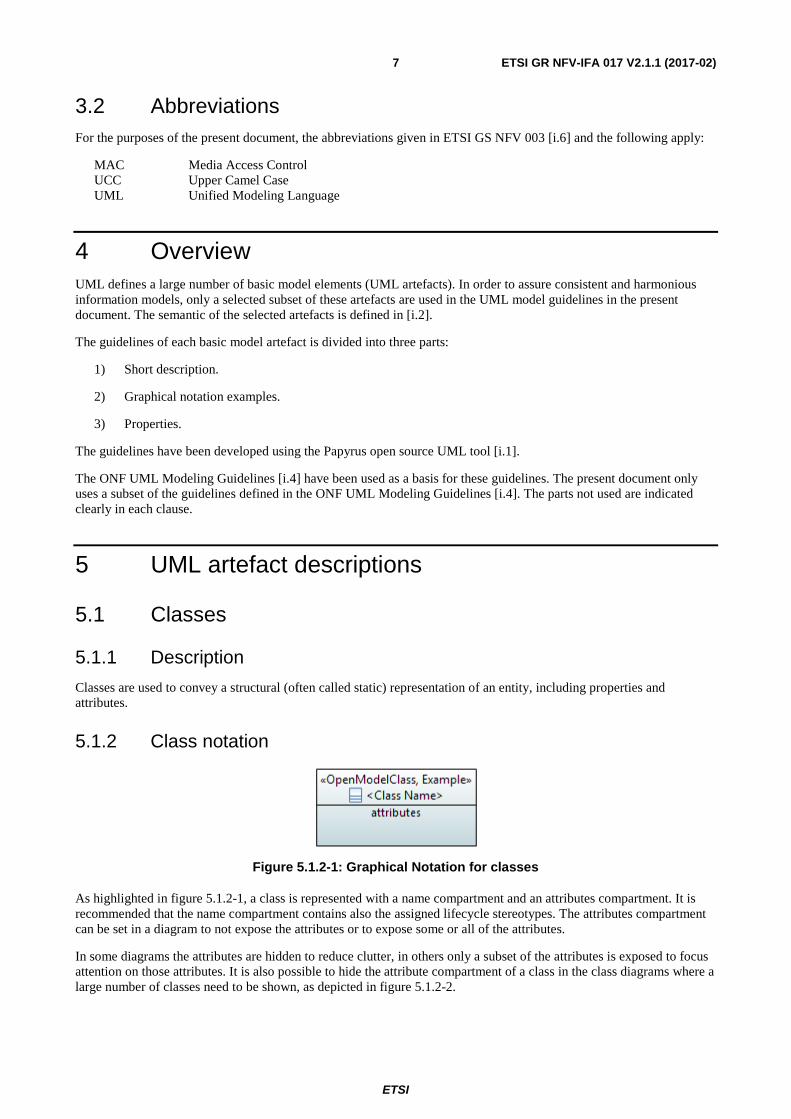
Figure 5.1.2-1: Graphical Notation for classes
As highlighted in figure 5.1.2-1, a class is represented with a name compartment and an attributes compartment. It is recommended that the name compartment contains also the assigned lifecycle stereotypes. The attributes compartment can be set in a diagram to not expose the attributes or to expose some or all of the attributes.
In some diagrams the attributes are hidden to reduce clutter, in others only a subset of the attributes is exposed to focus attention on those attributes. It is also possible to hide the attribute compartment of a class in the class diagrams where a large number of classes need to be shown, as depicted in figure 5.1.2-2.
ETSI
ETSI GR NFV-IFA 017 V2.1.1 (2017-02) 8
Figure 5.1.2-2: Graphical Notation for Classes without Attributes Compartment
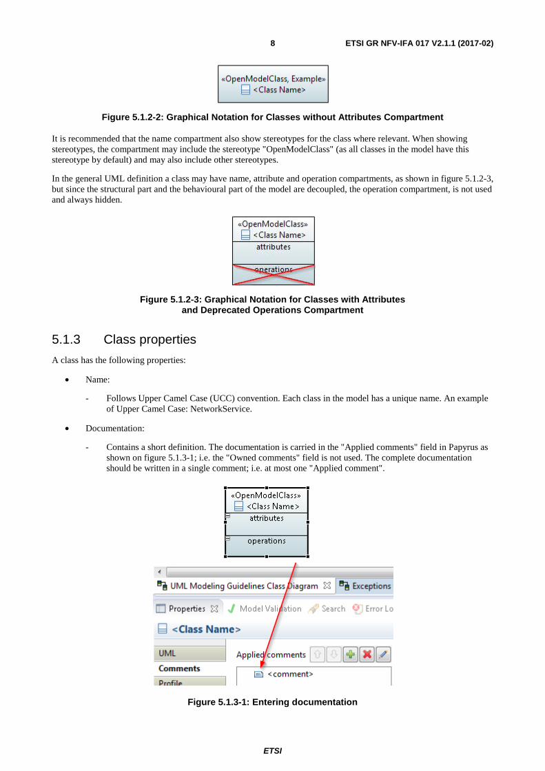
It is recommended that the name compartment also show stereotypes for the class where relevant. When showing stereotypes, the compartment may include the stereotype "OpenModelClass" (as all classes in the model have this stereotype by default) and may also include other stereotypes.
In the general UML definition a class may have name, attribute and operation compartments, as shown in figure 5.1.2-3, but since the structural part and the behavioural part of the model are decoupled, the operation compartment, is not used and always hidden.
Figure 5.1.2-3: Graphical Notation for Classes with Attributes and Deprecated Operations Compartment
5.1.3 Class properties
A class has the following properties:
• Name:
- Follows Upper Camel Case (UCC) convention. Each class in the model has a unique name. An example of Upper Camel Case: NetworkService.
• Documentation:
- Contains a short definition. The documentation is carried in the "Applied comments" field in Papyrus as shown on figure 5.1.3-1; i.e. the "Owned comments" field is not used. The complete documentation should be written in a single comment; i.e. at most one "Applied comment".
Figure 5.1.3-1: Entering documentation
ETSI
ETSI GR NFV-IFA 017 V2.1.1 (2017-02) 9
• Superclass:
- Inheritance may be used to deal with shared properties. Multiple inheritance is not supported in ETSI NFV Information Model.
• Abstract:
- Indicates if the object class can be instantiated or is just used for inheritance; i.e. abstract classes will not be instantiated.
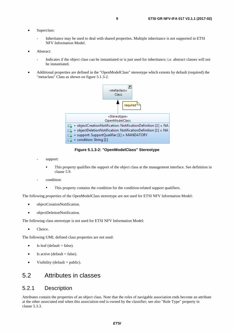
• Additional properties are defined in the "OpenModelClass" stereotype which extents by default (required) the "metaclass" Class as shown on figure 5.1.3-2.
Figure 5.1.3-2: "OpenModelClass" Stereotype
- support:
� This property qualifies the support of the object class at the management interface. See definition in clause 5.9.
- condition:
� This property contains the condition for the condition-related support qualifiers.
The following properties of the OpenModelClass stereotype are not used for ETSI NFV Information Model:
• objectCreationNotification.
• objectDeletionNotification.
The following class stereotype is not used for ETSI NFV Information Model:
• Choice.
The following UML defined class properties are not used:
• Is leaf (default = false).
• Is active (default = false).
• Visibility (default = public).
5.2 Attributes in classes
5.2.1 Description
Attributes contain the properties of an object class. Note that the roles of navigable association ends become an attribute at the other associated end when this association end is owned by the classifier; see also "Role Type" property in clause 5.3.3.
ETSI
ETSI GR NFV-IFA 017 V2.1.1 (2017-02) 10
NOTE: The association end can also be owned by the association itself in which case it does not become an attribute.
5.2.2 Attribute notation
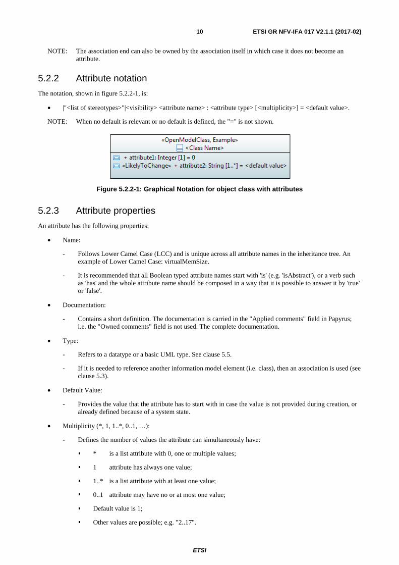
The notation, shown in figure 5.2.2-1, is:
• |"<list of stereotypes>"|<visibility> <attribute name> : <attribute type> [<multiplicity>] = <default value>.
NOTE: When no default is relevant or no default is defined, the "=" is not shown.
Figure 5.2.2-1: Graphical Notation for object class with attributes
5.2.3 Attribute properties
An attribute has the following properties:
• Name:
- Follows Lower Camel Case (LCC) and is unique across all attribute names in the inheritance tree. An example of Lower Camel Case: virtualMemSize.
- It is recommended that all Boolean typed attribute names start with 'is' (e.g. 'isAbstract'), or a verb such as 'has' and the whole attribute name should be composed in a way that it is possible to answer it by 'true' or 'false'.
• Documentation:
- Contains a short definition. The documentation is carried in the "Applied comments" field in Papyrus; i.e. the "Owned comments" field is not used. The complete documentation.
• Type:
- Refers to a datatype or a basic UML type. See clause 5.5.
- If it is needed to reference another information model element (i.e. class), then an association is used (see clause 5.3).
• Default Value:
- Provides the value that the attribute has to start with in case the value is not provided during creation, or already defined because of a system state.
• Multiplicity (*, 1, 1..*, 0..1, …):
- Defines the number of values the attribute can simultaneously have:
� * is a list attribute with 0, one or multiple values;
� 1 attribute has always one value;
� 1..* is a list attribute with at least one value;
� 0..1 attribute may have no or at most one value;
� Default value is 1;
� Other values are possible; e.g. "2..17".
ETSI
ETSI GR NFV-IFA 017 V2.1.1 (2017-02) 11
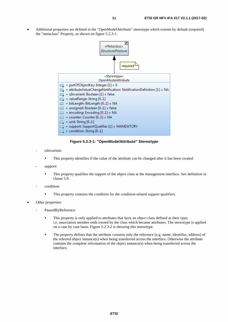
• Additional properties are defined in the "OpenModelAttribute" stereotype which extents by default (required) the "metaclass" Property, as shown on figure 5.2.3-1.
Figure 5.2.3-1: "OpenModelAttribute" Stereotype
- isInvariant:
� This property identifies if the value of the attribute can be changed after it has been created.
- support:
� This property qualifies the support of the object class at the management interface. See definition in clause 5.9.
- condition:
� This property contains the condition for the condition-related support qualifiers.
• Other properties:
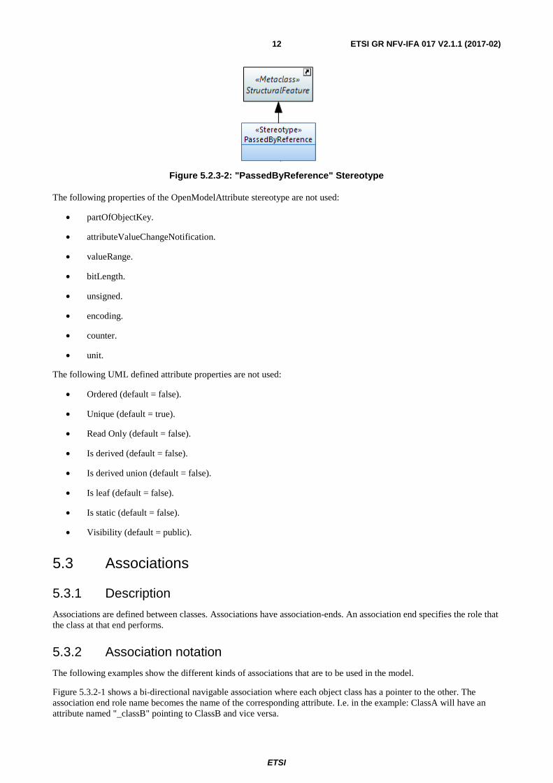
- PassedByReference:
� This property is only applied to attributes that have an object class defined as their type; i.e. association member ends owned by the class which became attributes. The stereotype is applied on a case by case basis. Figure 5.2.3-2 is showing this stereotype.
� The property defines that the attribute contains only the reference (e.g. name, identifier, address) of the referred object instance(s) when being transferred across the interface. Otherwise the attribute contains the complete information of the object instance(s) when being transferred across the interface.
ETSI
ETSI GR NFV-IFA 017 V2.1.1 (2017-02) 12
Figure 5.2.3-2: "PassedByReference" Stereotype
The following properties of the OpenModelAttribute stereotype are not used:
• partOfObjectKey.
• attributeValueChangeNotification.
• valueRange.
• bitLength.
• unsigned.
• encoding.
• counter.
• unit.
The following UML defined attribute properties are not used:
• Ordered (default = false).
• Unique (default = true).
• Read Only (default = false).
• Is derived (default = false).
• Is derived union (default = false).
• Is leaf (default = false).
• Is static (default = false).
• Visibility (default = public).
5.3 Associations
5.3.1 Description
Associations are defined between classes. Associations have association-ends. An association end specifies the role that the class at that end performs.
5.3.2 Association notation
The following examples show the different kinds of associations that are to be used in the model.
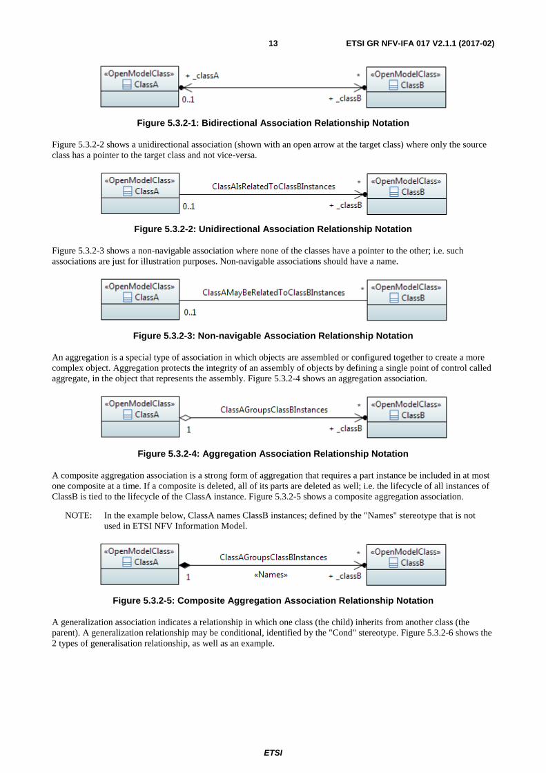
Figure 5.3.2-1 shows a bi-directional navigable association where each object class has a pointer to the other. The association end role name becomes the name of the corresponding attribute. I.e. in the example: ClassA will have an attribute named "_classB" pointing to ClassB and vice versa.
ETSI
ETSI GR NFV-IFA 017 V2.1.1 (2017-02) 13
Figure 5.3.2-1: Bidirectional Association Relationship Notation
Figure 5.3.2-2 shows a unidirectional association (shown with an open arrow at the target class) where only the source class has a pointer to the target class and not vice-versa.
Figure 5.3.2-2: Unidirectional Association Relationship Notation
Figure 5.3.2-3 shows a non-navigable association where none of the classes have a pointer to the other; i.e. such associations are just for illustration purposes. Non-navigable associations should have a name.
Figure 5.3.2-3: Non-navigable Association Relationship Notation
An aggregation is a special type of association in which objects are assembled or configured together to create a more complex object. Aggregation protects the integrity of an assembly of objects by defining a single point of control called aggregate, in the object that represents the assembly. Figure 5.3.2-4 shows an aggregation association.
Figure 5.3.2-4: Aggregation Association Relationship Notation
A composite aggregation association is a strong form of aggregation that requires a part instance be included in at most one composite at a time. If a composite is deleted, all of its parts are deleted as well; i.e. the lifecycle of all instances of ClassB is tied to the lifecycle of the ClassA instance. Figure 5.3.2-5 shows a composite aggregation association.
NOTE: In the example below, ClassA names ClassB instances; defined by the "Names" stereotype that is not used in ETSI NFV Information Model.
Figure 5.3.2-5: Composite Aggregation Association Relationship Notation
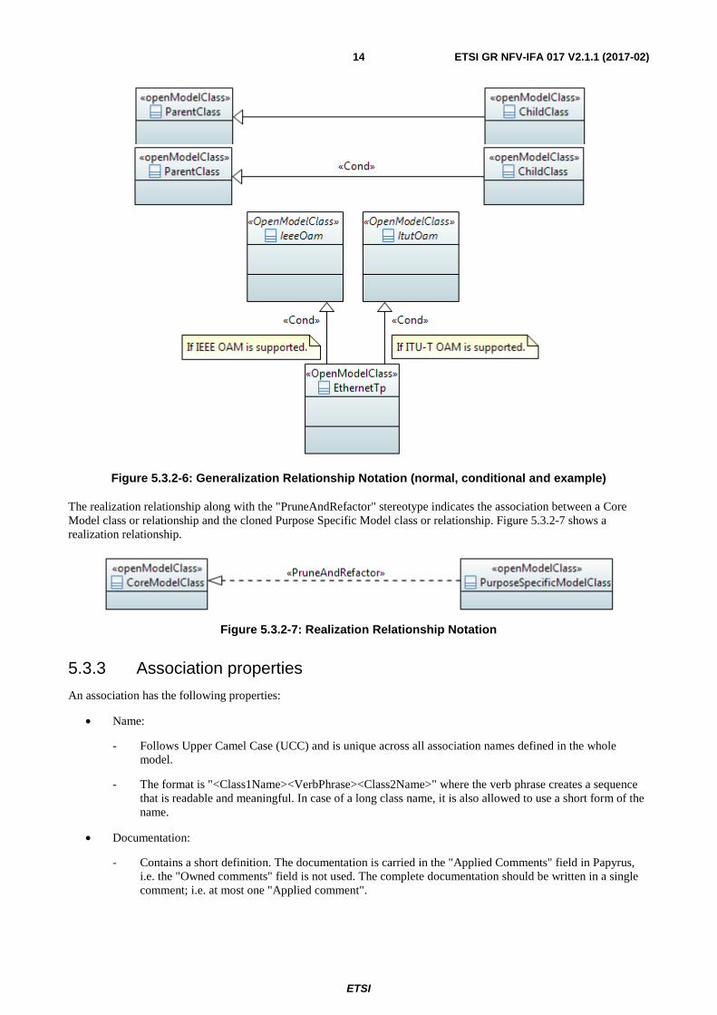
A generalization association indicates a relationship in which one class (the child) inherits from another class (the parent). A generalization relationship may be conditional, identified by the "Cond" stereotype. Figure 5.3.2-6 shows the 2 types of generalisation relationship, as well as an example.
ETSI
ETSI GR NFV-IFA 017 V2.1.1 (2017-02) 14
Figure 5.3.2-6: Generalization Relationship Notation (normal, conditional and example)
The realization relationship along with the "PruneAndRefactor" stereotype indicates the association between a Core Model class or relationship and the cloned Purpose Specific Model class or relationship. Figure 5.3.2-7 shows a realization relationship.
Figure 5.3.2-7: Realization Relationship Notation
5.3.3 Association properties
An association has the following properties:
• Name:
- Follows Upper Camel Case (UCC) and is unique across all association names defined in the whole model.
- The format is "<Class1Name><VerbPhrase><Class2Name>" where the verb phrase creates a sequence that is readable and meaningful. In case of a long class name, it is also allowed to use a short form of the name.
• Documentation:
- Contains a short definition. The documentation is carried in the "Applied Comments" field in Papyrus, i.e. the "Owned comments" field is not used. The complete documentation should be written in a single comment; i.e. at most one "Applied comment".
ETSI
ETSI GR NFV-IFA 017 V2.1.1 (2017-02) 15
• Abstract:
- Associations which are just for explanation to the reader of the model are defined as "abstract". Their ends are not navigable and have no role names. Abstract associations should not be taken into account in a protocol specific implementation.
• Type:
- The following types are used:
� inheritance;
� simple association (aggregation = none);
� composition (aggregation = composite);
� aggregation (aggregation = shared).
• Role Name:
- Follows Lower Camel Case (LCC) and identifies the role that the object plays at this end (Member End) of the association. Prefixing the role name with an underscore "_" is not needed in ETSI NFV Information Model.
- Only navigable Member Ends have role names and follow the definitions made for attributes in clause 5.2.
• Role Type:
- The type of the role is fixed to the class attached to the association end. Therefore it is important to define the type as passedByReference or passedByValue. The "PassedByReference" stereotype identifies that the role (becoming an attribute) that has the stereotype associated, contains only the reference (name, identifier, address) to the referred instance(s) when being transferred across the interface. Otherwise the role (becoming an attribute) contains the complete information of the instance(s) when being transferred across the interface.
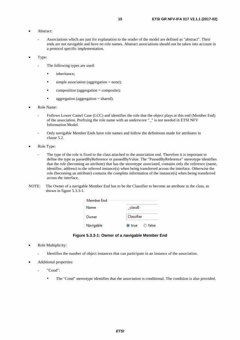
NOTE: The Owner of a navigable Member End has to be the Classifier to become an attribute in the class, as shown in figure 5.3.3-1.
Figure 5.3.3-1: Owner of a navigable Member End
• Role Multiplicity:
- Identifies the number of object instances that can participate in an instance of the association.
• Additional properties:
- "Cond":
� The "Cond" stereotype identifies that the association is conditional. The condition is also provided.
ETSI
ETSI GR NFV-IFA 017 V2.1.1 (2017-02) 16
- "StrictComposite":
� The "StrictComposite" stereotype can only be applied to associations with a composite end (i.e. composite aggregation association). It means that the content of the composed classes is part of the parent class and has no opportunity for independent lifecycle. The composed classes are essentially carrying attributes of the parent class where the composite is used to provide grouping of similar properties. The composed classes just provide groups of attributes for the parent class; i.e. they are abstract and cannot be instantiated.
� Whereas in an association with a composite end that is not StrictComposite the composed class is a part that has a restricted independent lifecycle. In this case an instance of the composed class can be created and deleted in the context of the parent class and should be represented as a separate instance from the parent in an implementation. This is especially true where there is a recursive composition. It is possible that in some cases the composed instance could move from one parent to another so long as it exists with one parent only at all points of the transaction. This move is not meaningful for a class associated via a StrictComposite association.
- "PruneAndRefactor":
� This "PruneAndRefactor" stereotype identifies that a realization association is used to identify pruning and refactoring.
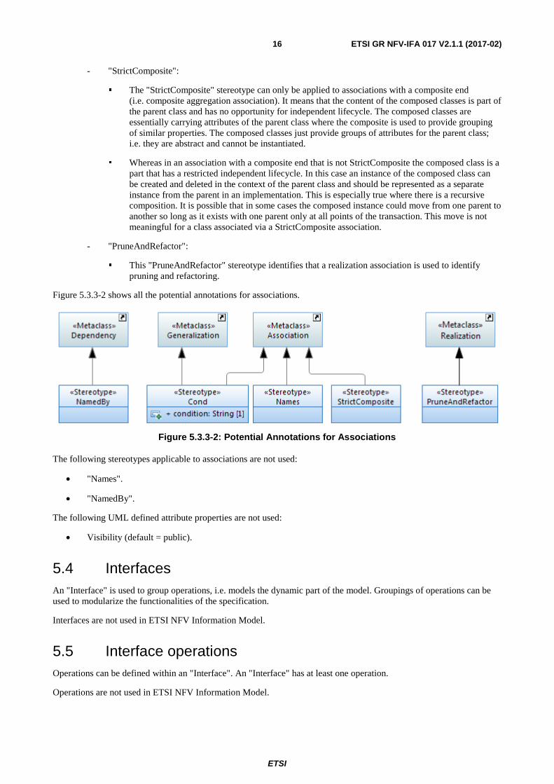
Figure 5.3.3-2 shows all the potential annotations for associations.
Figure 5.3.3-2: Potential Annotations for Associations
The following stereotypes applicable to associations are not used:
• "Names".
• "NamedBy".
The following UML defined attribute properties are not used:
• Visibility (default = public).
5.4 Interfaces An "Interface" is used to group operations, i.e. models the dynamic part of the model. Groupings of operations can be used to modularize the functionalities of the specification.
Interfaces are not used in ETSI NFV Information Model.
5.5 Interface operations Operations can be defined within an "Interface". An "Interface" has at least one operation.
Operations are not used in ETSI NFV Information Model.
ETSI
ETSI GR NFV-IFA 017 V2.1.1 (2017-02) 17
5.6 Operation parameters Parameters define the input and output signals of an operation.
Parameters are not used in ETSI NFV Information Model.
5.7 Notifications
5.7.1 Description
The UML "Signal" is used to define the content of a notification. The information is defined in the attributes of the "Signal".
5.7.2 Notification notation
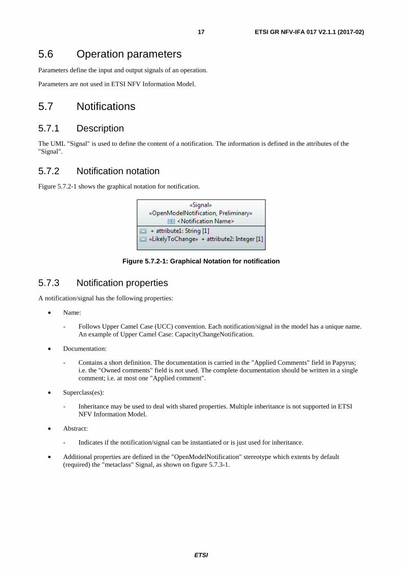
Figure 5.7.2-1 shows the graphical notation for notification.
Figure 5.7.2-1: Graphical Notation for notification
5.7.3 Notification properties
A notification/signal has the following properties:
• Name:
- Follows Upper Camel Case (UCC) convention. Each notification/signal in the model has a unique name. An example of Upper Camel Case: CapacityChangeNotification.
• Documentation:
- Contains a short definition. The documentation is carried in the "Applied Comments" field in Papyrus; i.e. the "Owned comments" field is not used. The complete documentation should be written in a single comment; i.e. at most one "Applied comment".
• Superclass(es):
- Inheritance may be used to deal with shared properties. Multiple inheritance is not supported in ETSI NFV Information Model.
• Abstract:
- Indicates if the notification/signal can be instantiated or is just used for inheritance.
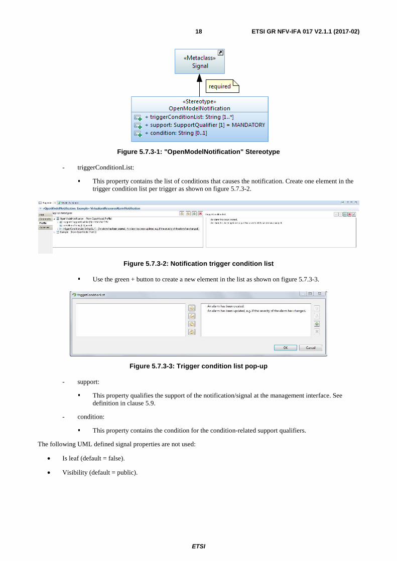
• Additional properties are defined in the "OpenModelNotification" stereotype which extents by default (required) the "metaclass" Signal, as shown on figure 5.7.3-1.
ETSI
ETSI GR NFV-IFA 017 V2.1.1 (2017-02) 18
Figure 5.7.3-1: "OpenModelNotification" Stereotype
- triggerConditionList:
� This property contains the list of conditions that causes the notification. Create one element in the trigger condition list per trigger as shown on figure 5.7.3-2.
Figure 5.7.3-2: Notification trigger condition list
� Use the green + button to create a new element in the list as shown on figure 5.7.3-3.
Figure 5.7.3-3: Trigger condition list pop-up
- support:
� This property qualifies the support of the notification/signal at the management interface. See definition in clause 5.9.
- condition:
� This property contains the condition for the condition-related support qualifiers.
The following UML defined signal properties are not used:
• Is leaf (default = false).
• Visibility (default = public).
ETSI
ETSI GR NFV-IFA 017 V2.1.1 (2017-02) 19
5.8 Data Types
5.8.1 Description
Types are used as type definitions of attributes and parameters.
Data Types are divided into 3 categories:
• (complex) DataTypes (further structured; e.g. Host which combines ipAddress and domainName).
• Primitive Types (not further structured; e.g. Integer, MAC address).
• Enumerations.
5.8.2 Type notation
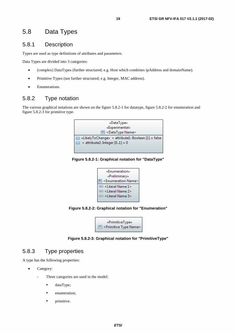
The various graphical notations are shown on the figure 5.8.2-1 for datatype, figure 5.8.2-2 for enumeration and figure 5.8.2-3 for primitive type.
Figure 5.8.2-1: Graphical notation for "DataType"
Figure 5.8.2-2: Graphical notation for "Enumeration"
Figure 5.8.2-3: Graphical notation for "PrimitiveType"
5.8.3 Type properties
A type has the following properties:
• Category:
- Three categories are used in the model:
� dataType;
� enumeration;
� primitive.
ETSI
ETSI GR NFV-IFA 017 V2.1.1 (2017-02) 20
• Name:
- Follows Upper Camel Case (UCC) convention. Each datatype in the model has a unique name.
• Documentation:
- Contains a short definition. The documentation is carried in the in Papyrus; i.e. the "Owned comments" field is not used. The complete documentation should be written in a single comment; i.e. at most one "Applied comment".
• Datatype attributes (only for dataTypes):
- Follow the definitions made for attributes in clause 5.2with the following exceptions:
� the isInvariant property can be ignored and is fixed to "true";
� the notification property can be ignored and is fixed to "NA".
• Enumeration literals (only for enumerations):
- The name contains only upper case characters where the words are separated by "_". Example: "CHANGED_DATA".
The following stereotypes applicable to data types are not used:
• Choice.
• Exception.
The following UML/Papyrus defined attribute properties that are not used:
• Is abstract (default = false).
• Is leaf (default = false).
5.8.4 UML Primitive Types
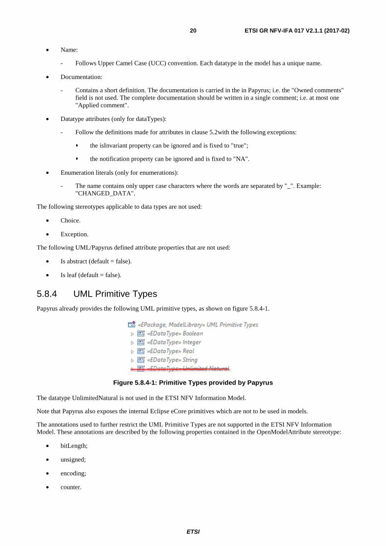
Papyrus already provides the following UML primitive types, as shown on figure 5.8.4-1.
Figure 5.8.4-1: Primitive Types provided by Papyrus
The datatype UnlimitedNatural is not used in the ETSI NFV Information Model.
Note that Papyrus also exposes the internal Eclipse eCore primitives which are not to be used in models.
The annotations used to further restrict the UML Primitive Types are not supported in the ETSI NFV Information Model. These annotations are described by the following properties contained in the OpenModelAttribute stereotype:
• bitLength;
• unsigned;
• encoding;
• counter.
ETSI
ETSI GR NFV-IFA 017 V2.1.1 (2017-02) 21
5.8.5 Pre-defined Data Types
No separate model library defining additional common data types is used in ETSI NFV Information Model.
Additional primitive types should be defined in the CommonTypesModule (NfvInformationModel::NFVCoreModel::NFVCommonDomain::CommonTypesModule).
5.9 Qualifiers and conditions This clause defines the qualifiers applicable for model elements specified in this document, e.g. the "OpenModelClass" (see clause 5.1.2), the "OpenModelAttribute" (see clause 5.2.2) and the <<OpenModelNotification>> (see clause 5.3.2). The qualifications are M, O, CM and CO. Their meanings are specified in this clause. This type of qualifier is called Support Qualifier:
• Definition of M (Mandatory) qualification:
- The model element needs to be supported.
• Definition of O (Optional) qualification:
- The model element may, but needs not to, be supported.
• Definition of CM (Conditional-Mandatory) qualification:
- The model element needs to be supported under certain conditions. If the specified conditions are met then the model element needs to be supported.
• Definition of CO (Conditional-Optional) qualification:
- The model element may, but needs not to, be supported under certain conditions. If the specified conditions are met then the model element may, but needs not to, be supported. If the specified conditions are not met then the model element needs to be supported.
The qualification C (Conditional) is not supported by the ETSI NFV Information Model.
The condition property contains the condition for the condition-related support qualifiers (CM, CO).
The use of conditional classes to group conditions is not supported by the ETSI NFV Information Model.
5.10 Use cases Use case diagrams define actors in a system and the defined behaviour over a specific interface.
Use case diagrams are not used in ETSI NFV Information Model.
5.11 Activities Activities defined in UML are used for business process modeling.
Activities are not used in ETSI NFV Information Model.
5.12 State machines State machines define state transitions and triggers that are needed for the transitions to take place.
State machines are not used in ETSI NFV Information Model.
ETSI
ETSI GR NFV-IFA 017 V2.1.1 (2017-02) 22
6 UML profile definitions
6.1 Additional Properties for individual UML artefacts Clause 5 has already described the additional properties for each UML artefact. All defined stereotypes are shown as an overview in figures 6.1-1 and 6.1-2 and table 6.1-1.
Figure 6.1-1: Required "Stereotypes"
ETSI
ETSI GR NFV-IFA 017 V2.1.1 (2017-02) 23
Figure 6.1-2: Optional "Stereotypes"
The NFV Information Model is only supporting a subset of the stereotypes and properties of the OpenModel profile. The stereotypes and properties not supported by the ETSI NFV Information Model are marked with an asterisk in the table 6.1-1.
ETSI
ETSI GR NFV-IFA 017 V2.1.1 (2017-02) 24
Table 6.1-1: UML Artefact Properties Defined in Complex "Stereotypes"
Stereotype Name of property Type Allowed values Default value Associated to
metaclass
OpenModelClass
objectCreation Notification * enumeration
NO, YES, NA
NA
Class
objectDeletion Notification * enumeration
NO, YES, NA
NA
support enumeration
MANDATORY, OPTIONAL, CONDITIONAL_ MANDATORY, CONDITIONAL_ OPTIONAL, CONDITIONAL
MANDATORY
condition string
OpenModelAttribute
partOfObjectKey * Integer 0, 1, 2, 3, etc. 0
Property
attributeValue Change Notification *
enumeration NO, YES, NA
NA
isInvariant Boolean true/false false valueRange * string NA
bitLength * BitLength
NA, LENGTH_8_BIT, LENGTH_16_BIT, LENGTH_32_BIT, LENGTH_64_BIT
NA
Unsigned * Boolean true/false false
Encoding * Encoding
NA, BASE_64, HEX, OCTET,
NA
Counter * Counter
NA, COUNTER, GAUGE, ZERO_COUNTER,
NA
Unit * String
support enumeration
MANDATORY, OPTIONAL, CONDITIONAL_ MANDATORY, CONDITIONAL_ OPTIONAL, CONDITIONAL *
MANDATORY
condition string
OpenModelInterface *
Support * enumeration
MANDATORY, OPTIONAL, CONDITIONAL_ MANDATORY, CONDITIONAL_ OPTIONAL, CONDITIONAL
MANDATORY Interface
Condition * string
OpenModelOperation *
isOperationIdempotent * Boolean true/false false
Operation
isAtomic * Boolean true/false false
Support * enumeration
MANDATORY, OPTIONAL, CONDITIONAL_ MANDATORY, CONDITIONAL_ OPTIONAL, CONDITIONAL
MANDATORY
Condition * string
ETSI
ETSI GR NFV-IFA 017 V2.1.1 (2017-02) 25
Stereotype Name of property Type Allowed values Default value Associated to
metaclass
OpenModelParameter *
valueRange * string NA
Parameter Support * enumeration
MANDATORY, OPTIONAL, CONDITIONAL_ MANDATORY, CONDITIONAL_ OPTIONAL, CONDITIONAL
MANDATORY
Condition * string
OpenModelNotification
triggerConditionList String
Signal support enumeration
MANDATORY, OPTIONAL, CONDITIONAL_ MANDATORY, CONDITIONAL_ OPTIONAL, CONDITIONAL
MANDATORY
condition string
6.2 Additional Properties for all UML artefacts
6.2.1 LifecycleState Property
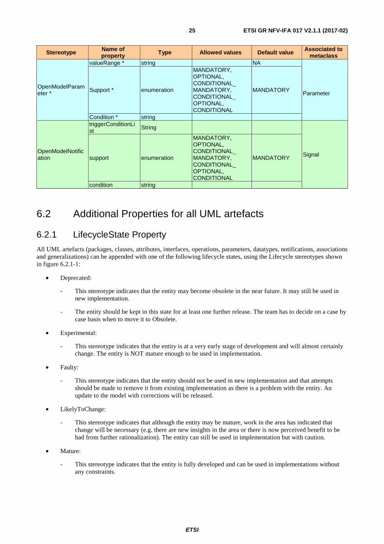
All UML artefacts (packages, classes, attributes, interfaces, operations, parameters, datatypes, notifications, associations and generalizations) can be appended with one of the following lifecycle states, using the Lifecycle stereotypes shown in figure 6.2.1-1:
• Deprecated:
- This stereotype indicates that the entity may become obsolete in the near future. It may still be used in new implementation.
- The entity should be kept in this state for at least one further release. The team has to decide on a case by case basis when to move it to Obsolete.
• Experimental:
- This stereotype indicates that the entity is at a very early stage of development and will almost certainly change. The entity is NOT mature enough to be used in implementation.
• Faulty:
- This stereotype indicates that the entity should not be used in new implementation and that attempts should be made to remove it from existing implementation as there is a problem with the entity. An update to the model with corrections will be released.
• LikelyToChange:
- This stereotype indicates that although the entity may be mature, work in the area has indicated that change will be necessary (e.g. there are new insights in the area or there is now perceived benefit to be had from further rationalization). The entity can still be used in implementation but with caution.
• Mature:
- This stereotype indicates that the entity is fully developed and can be used in implementations without any constraints.
ETSI
ETSI GR NFV-IFA 017 V2.1.1 (2017-02) 26
• Obsolete:
- This stereotype indicates that the entity should not be used in new implementation and that attempts should be made to remove it from existing implementation.
- The entity should be kept in the model at least for one further release. The team has to decide on a case by case basis when to remove it from the model.
• Preliminary:
- This state indicates that the entity is at a relatively early stage of development and is likely to change, but is mature enough to be used in implementation.
Rules:
One and only one lifecycle state has to be associated to every UML artefact. It is recommended that every new UML artefact is initially annotated with the "Experimental" lifecycle stereotype.
Figure 6.2.1-1: Lifecycle "Stereotypes"
ETSI
ETSI GR NFV-IFA 017 V2.1.1 (2017-02) 27
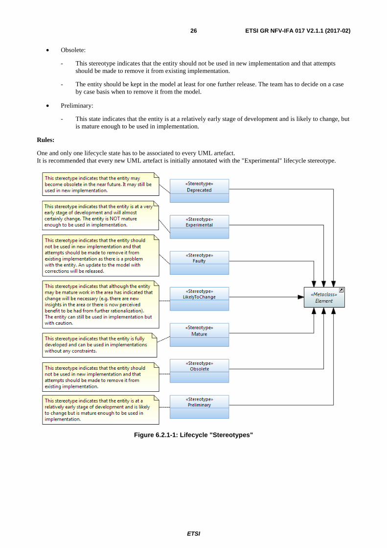
The following state machine diagram, presented in figure 6.2.1-2, shows the defined state transitions.
Figure 6.2.1-2: OpenModelProfile LifecycleState State Machine
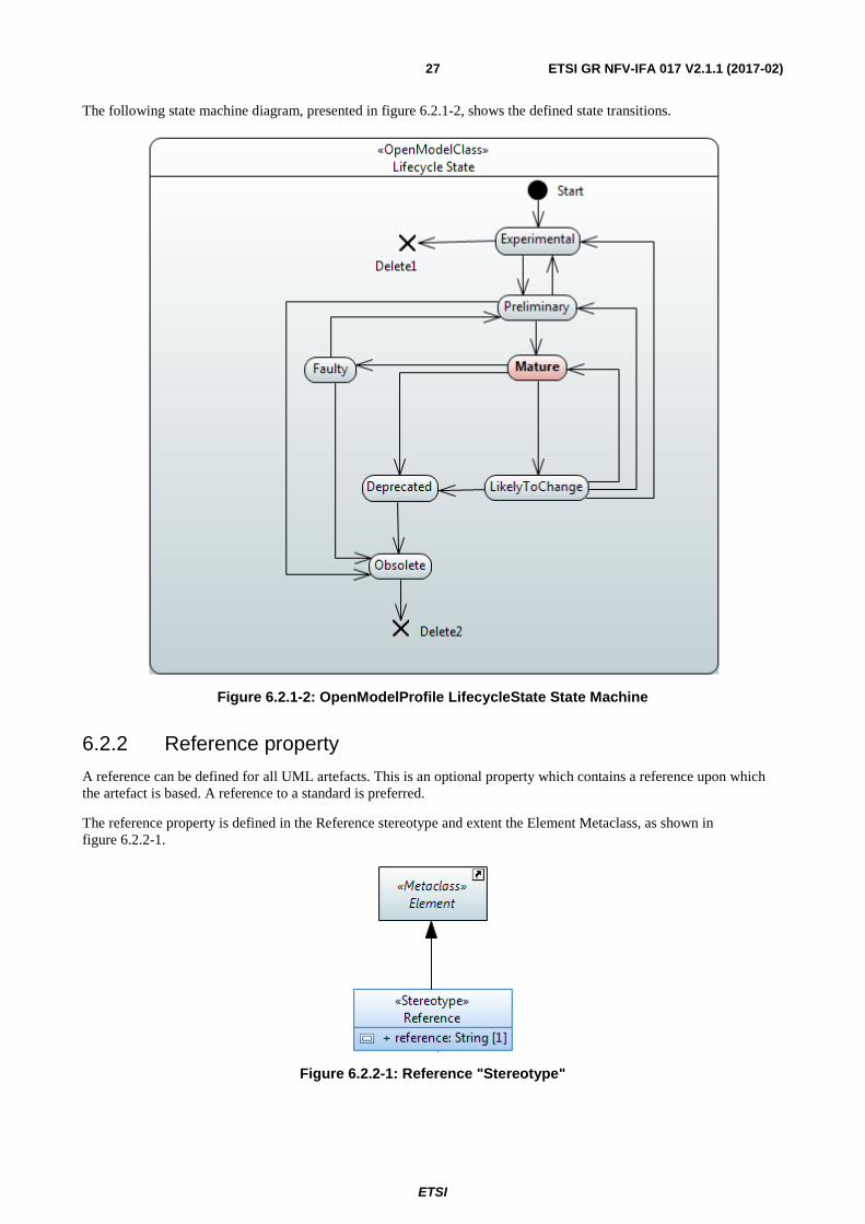
6.2.2 Reference property
A reference can be defined for all UML artefacts. This is an optional property which contains a reference upon which the artefact is based. A reference to a standard is preferred.
The reference property is defined in the Reference stereotype and extent the Element Metaclass, as shown in figure 6.2.2-1.
Figure 6.2.2-1: Reference "Stereotype"
ETSI
ETSI GR NFV-IFA 017 V2.1.1 (2017-02) 28
6.2.3 Example property
This is an optional property which can be defined for all UML artefacts.
It is defined as a stereotype, as shown in figure 6.2.3-1, and indicates that the entity is NOT to be used in implementation and is in the model simply to assist in the understanding of the model (e.g. a specialization of a generalized class where the generalized class is to be used as is and the specialization is simply offered to more easily illustrate an application of the generalized class).
Figure 6.2.3-1: Example "Stereotype"
7 Recommended Modeling Patterns
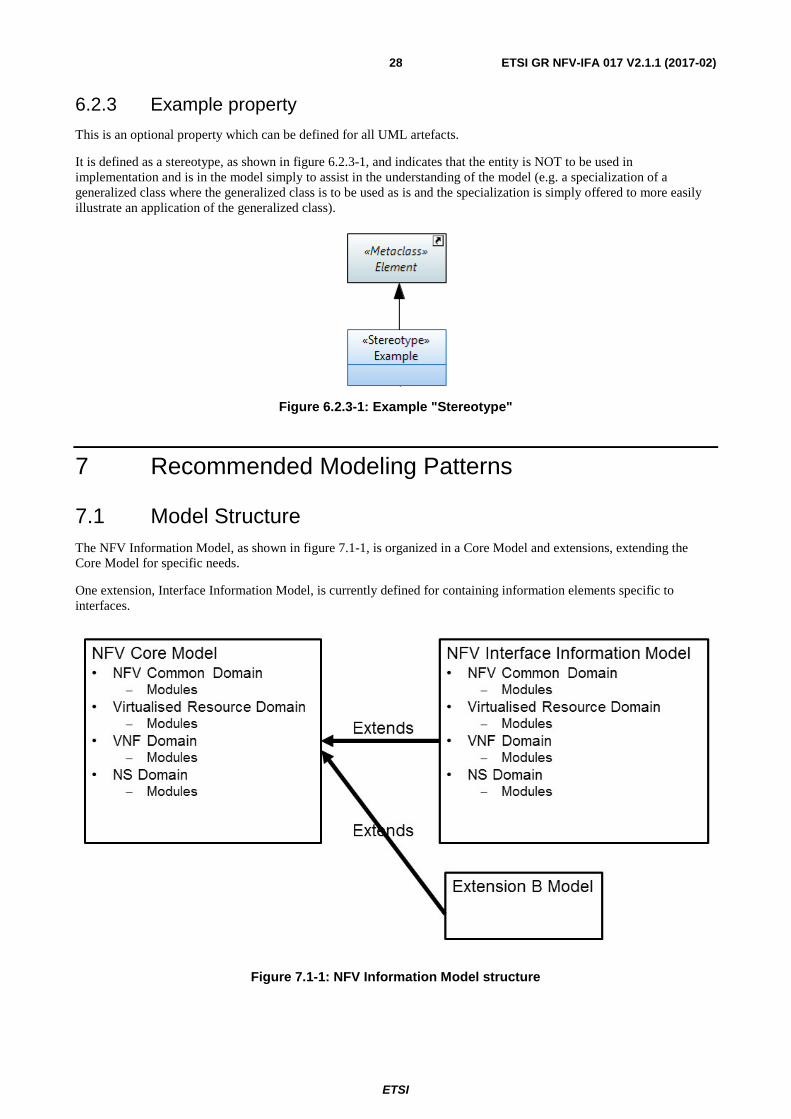
7.1 Model Structure The NFV Information Model, as shown in figure 7.1-1, is organized in a Core Model and extensions, extending the Core Model for specific needs.
One extension, Interface Information Model, is currently defined for containing information elements specific to interfaces.
Figure 7.1-1: NFV Information Model structure
ETSI
ETSI GR NFV-IFA 017 V2.1.1 (2017-02) 29
Each model is structured in Domains. Four domains are defined today:
• NFV Common Domain.
• Virtualised Resource Domain.
• VNF Domain.
• NS Domain.
Each domain can be structured in modules (represented by packages) and modules can be structured in sub-modules.
If a module is structured in sub-modules, it should only contain sub-modules and no other artefact (class, data type, etc.)
The ETSI NFV Information Model does not use pre-defined packages (i.e. by type of artefact) within the modules. Use of such pre-defined packages would break the generation of the model documentation using Gendoc.
7.2 Use of XOR/Choice/Proxy class
7.2.1 Xor constraint
7.2.1.1 Description
"A Constraint is an assertion that indicates a restriction that has to be satisfied by any valid realization of the model containing the Constraint. A Constraint is attached to a set of constrainedElements, and it represents additional semantic information about those Elements.…", an extract from clause 7.6.1 Constraint of the OMG Unified Modeling Language (OMG UML) specification [i.3].
For a constraint that applies to two elements such as two associations, the constraint needs to be shown as a dashed line between the elements labelled by the constraint string (in braces). The constraint string, in this case, is xor.
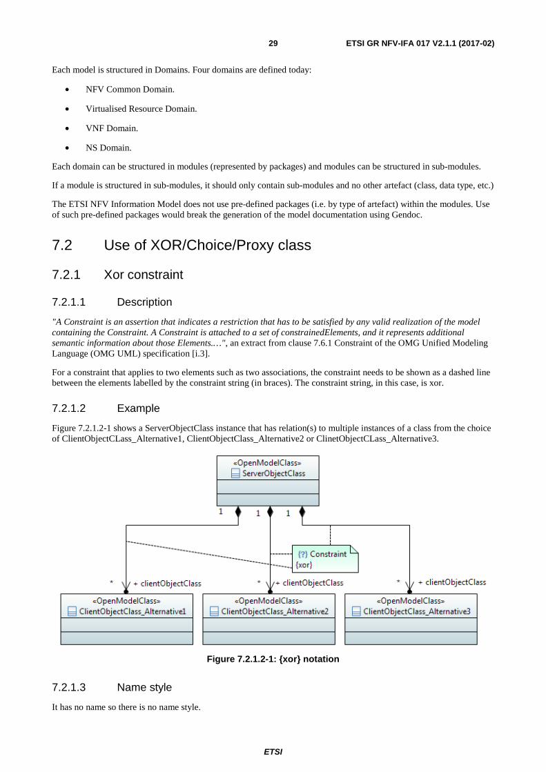
7.2.1.2 Example
Figure 7.2.1.2-1 shows a ServerObjectClass instance that has relation(s) to multiple instances of a class from the choice of ClientObjectCLass_Alternative1, ClientObjectClass_Alternative2 or ClinetObjectCLass_Alternative3.
Figure 7.2.1.2-1: {xor} notation
7.2.1.3 Name style
It has no name so there is no name style.
ETSI
ETSI GR NFV-IFA 017 V2.1.1 (2017-02) 30
7.2.2 "Choice"
The "Choice" stereotype represents one of a set of classes (when used as an information model element) or one of a set of data types (when used as an operations model element).
This stereotype is not supported in the ETSI NFV Information Model.
7.2.3 Proxy class Modeling
There are cases where an attribute or parameter may contain different kinds of classes. This would require an attribute/parameter per kind of class. In order to reduce the number of attributes/parameters it is recommended to define a proxy class and let a single attribute/parameter point to this class.
This modeling pattern is not supported in the ETSI NFV Information Model.
7.3 UML diagram guidelines
7.3.1 Recommendations
Classes and their relationships are presented in class diagrams.
It is recommended to create:
• An overview class diagram containing all classes related to a specific management area (e.g. module). - The class name compartment should contain the location of the class definition (e.g. "Qualified Name"). Depending on the complexity of the diagram, attributes and association roles might be shown or might be omitted in the overview diagram.
• A separate inheritance class diagram in case the overview diagram would be overloaded when showing the inheritance structure (Inheritance Class Diagram).
• A class diagram containing the user defined data types (Type Definitions Diagram).
• Additional class diagrams to show specific parts of the specification in detail as needed. Attributes and association roles can be shown on these diagrams.
7.3.2 Using colors
The colour conventions defined in clause 5.2 of ETSI GR NFV-IFA 015 [i.5] are applicable.
7.3.3 Style sheets
Classes in class diagrams should not show the "nestedclassifiers" and "operations" compartments.
Data Types in class diagrams should not show the "operations" compartment.
The use of the CompartmentRestritions.css style sheet fulfil these requirements.
Attributes in class diagrams should only show name, type, multiplicity and defaultValue.
Attributes in class diagrams should not show the stereotype "OpenModelAttribute".
The use of the NoStereotypesDiagram.css style sheet fulfil these requirements.

ETSI
ETSI GR NFV-IFA 017 V2.1.1 (2017-02) 31
Annex A: Authors & contributors The following people have contributed to the present document:
Rapporteur: Marc Flauw, Hewlett-Packard Enterprise
Other contributors: Peter Wörndle, Ericsson Bruno Chatras, ORANGE

ETSI
ETSI GR NFV-IFA 017 V2.1.1 (2017-02) 32
History
Document history
V2.1.1 February 2017 Publication