etsi gr nfv 001 v1.2 · etsi gr nfv 001 v1.2.1 (2017-05) network functions virtualisation (nfv);...
TRANSCRIPT
ETSI GR NFV 001 V1.2.1 (2017-05)
Network Functions Virtualisation (NFV); Use Cases
Disclaimer
The present document has been produced and approved by the Network Functions Virtualisation (NFV) ETSI Industry Specification Group (ISG) and represents the views of those members who participated in this ISG.
It does not necessarily represent the views of the entire ETSI membership.
GROUP REPORT
ETSI
ETSI GR NFV 001 V1.2.1 (2017-05)2
Reference RGR/NFV-001ed121
Keywords NFV, use case
ETSI
650 Route des Lucioles F-06921 Sophia Antipolis Cedex - FRANCE
Tel.: +33 4 92 94 42 00 Fax: +33 4 93 65 47 16
Siret N° 348 623 562 00017 - NAF 742 C
Association à but non lucratif enregistrée à la Sous-Préfecture de Grasse (06) N° 7803/88
Important notice
The present document can be downloaded from: http://www.etsi.org/standards-search
The present document may be made available in electronic versions and/or in print. The content of any electronic and/or print versions of the present document shall not be modified without the prior written authorization of ETSI. In case of any
existing or perceived difference in contents between such versions and/or in print, the only prevailing document is the print of the Portable Document Format (PDF) version kept on a specific network drive within ETSI Secretariat.
Users of the present document should be aware that the document may be subject to revision or change of status. Information on the current status of this and other ETSI documents is available at
https://portal.etsi.org/TB/ETSIDeliverableStatus.aspx
If you find errors in the present document, please send your comment to one of the following services: https://portal.etsi.org/People/CommiteeSupportStaff.aspx
Copyright Notification
No part may be reproduced or utilized in any form or by any means, electronic or mechanical, including photocopying and microfilm except as authorized by written permission of ETSI.
The content of the PDF version shall not be modified without the written authorization of ETSI. The copyright and the foregoing restriction extend to reproduction in all media.
© European Telecommunications Standards Institute 2017.
All rights reserved.
DECTTM, PLUGTESTSTM, UMTSTM and the ETSI logo are Trade Marks of ETSI registered for the benefit of its Members. 3GPPTM and LTE™ are Trade Marks of ETSI registered for the benefit of its Members and
of the 3GPP Organizational Partners. oneM2M logo is protected for the benefit of its Members
GSM® and the GSM logo are Trade Marks registered and owned by the GSM Association.
ETSI
ETSI GR NFV 001 V1.2.1 (2017-05)3
Contents
Intellectual Property Rights ................................................................................................................................ 8
Foreword ............................................................................................................................................................. 8
Modal verbs terminology .................................................................................................................................... 8
1 Scope ........................................................................................................................................................ 9
2 References ................................................................................................................................................ 9
2.1 Normative references ......................................................................................................................................... 9
2.2 Informative references ........................................................................................................................................ 9
3 Abbreviations ......................................................................................................................................... 10
4 Overview ................................................................................................................................................ 12
5 Roles ....................................................................................................................................................... 13
6 Use Case #1: Network Function Virtualisation Infrastructure as a Service (NFVIaaS) ........................ 14
6.1 Motivation ........................................................................................................................................................ 14
6.2 Detailed User Story #1 - Compute Service Instantiation .................................................................................. 17
6.2.1 Summary ..................................................................................................................................................... 17
6.2.2 Actor(s) ....................................................................................................................................................... 17
6.2.3 Pre-Conditions ............................................................................................................................................ 17
6.2.4 Begins When ............................................................................................................................................... 17
6.2.5 Description .................................................................................................................................................. 17
6.2.6 End When ................................................................................................................................................... 17
6.2.7 Post-Conditions ........................................................................................................................................... 17
6.2.8 Exceptions................................................................................................................................................... 17
6.3 Detailed User Story #2 - Storage Service Instantiation .................................................................................... 18
6.3.1 Summary ..................................................................................................................................................... 18
6.3.2 Actor(s) ....................................................................................................................................................... 18
6.3.3 Pre-Conditions ............................................................................................................................................ 18
6.3.4 Begins When ............................................................................................................................................... 18
6.3.5 Description .................................................................................................................................................. 18
6.3.6 End When ................................................................................................................................................... 18
6.3.7 Post-Conditions ........................................................................................................................................... 18
6.3.8 Exceptions................................................................................................................................................... 18
6.4 Detailed User Story #3 - Network Service Instantiation .................................................................................. 19
6.4.1 Summary ..................................................................................................................................................... 19
6.4.2 Actor(s) ....................................................................................................................................................... 19
6.4.3 Pre-Conditions ............................................................................................................................................ 19
6.4.4 Begins When ............................................................................................................................................... 19
6.4.5 Description .................................................................................................................................................. 19
6.4.6 End When ................................................................................................................................................... 19
6.4.7 Post-Conditions ........................................................................................................................................... 19
6.4.8 Exceptions................................................................................................................................................... 19
6.5 Virtualisation Target......................................................................................................................................... 20
6.6 Coexistence of Virtualised and Non-Virtualised Network Functions .............................................................. 21
6.7 Problem description/Issues ............................................................................................................................... 21
7 Use Case #2: VNF Forwarding Graphs .................................................................................................. 21
7.1 Motivation ........................................................................................................................................................ 21
7.2 Detailed User Story .......................................................................................................................................... 22
7.2.1 Summary ..................................................................................................................................................... 22
7.2.2 Actor(s) ....................................................................................................................................................... 25
7.2.3 Pre-Conditions ............................................................................................................................................ 25
7.2.4 Begins When ............................................................................................................................................... 25
7.2.5 Description .................................................................................................................................................. 26
7.2.6 End When ................................................................................................................................................... 26
7.2.7 Post-Conditions ........................................................................................................................................... 26
ETSI
ETSI GR NFV 001 V1.2.1 (2017-05)4
7.2.8 Exceptions................................................................................................................................................... 26
7.2.9 Virtualisation Target ................................................................................................................................... 26
7.3 Coexistence of Virtualised and Non-Virtualised Network Functions .............................................................. 27
7.4 Problem description/Issues ............................................................................................................................... 27
8 Use Case #3: Virtualisation of Mobile Core Network and IMS............................................................. 28
8.1 Motivation ........................................................................................................................................................ 28
8.2 Detailed User Story .......................................................................................................................................... 28
8.2.1 Summary ..................................................................................................................................................... 28
8.2.2 Actor(s) ....................................................................................................................................................... 28
8.2.3 Pre-Conditions ............................................................................................................................................ 29
8.2.4 Begins When ............................................................................................................................................... 29
8.2.5 Description .................................................................................................................................................. 29
8.2.6 End When ................................................................................................................................................... 29
8.2.7 Post-Conditions ........................................................................................................................................... 29
8.2.8 Exceptions................................................................................................................................................... 29
8.2.9 Virtualisation Target ................................................................................................................................... 29
8.3 Coexistence of Virtualised and Non-Virtualised Network Functions .............................................................. 29
8.4 Problem description/Issues ............................................................................................................................... 31
9 Use Case #4: Virtualisation of Mobile base station ............................................................................... 32
9.1 Motivation ........................................................................................................................................................ 32
9.2 Detailed User Story .......................................................................................................................................... 32
9.2.1 Summary ..................................................................................................................................................... 32
9.2.2 Actor(s) ....................................................................................................................................................... 32
9.2.3 Pre-Conditions ............................................................................................................................................ 32
9.2.4 Begins When ............................................................................................................................................... 32
9.2.5 Description .................................................................................................................................................. 33
9.2.6 End When ................................................................................................................................................... 33
9.2.7 Post-Conditions ........................................................................................................................................... 33
9.2.8 Exceptions................................................................................................................................................... 33
9.2.9 Virtualisation Target ................................................................................................................................... 33
9.3 Coexistence of Virtualised and Non-Virtualised Network Functions .............................................................. 34
9.4 Problem description/Issues ............................................................................................................................... 34
10 Use Case #5: Virtualisation of the Home Environment ......................................................................... 35
10.1 Motivation ........................................................................................................................................................ 35
10.2 Detailed User Story .......................................................................................................................................... 36
10.2.1 Summary ..................................................................................................................................................... 36
10.2.2 Actor(s) ....................................................................................................................................................... 37
10.2.3 Pre-Conditions ............................................................................................................................................ 37
10.2.4 Begins When ............................................................................................................................................... 37
10.2.5 Description .................................................................................................................................................. 38
10.2.6 End When ................................................................................................................................................... 38
10.2.7 Post-Conditions ........................................................................................................................................... 38
10.2.8 Exceptions................................................................................................................................................... 38
10.2.9 Virtualisation Target ................................................................................................................................... 38
10.3 Coexistence of Virtualised and Non-Virtualised Network Functions .............................................................. 39
10.4 Problem description/Issues ............................................................................................................................... 41
11 Use Case #6: Virtual Content Delivery Network (vCDN) - Fulfilment ................................................. 42
11.1 Motivation ........................................................................................................................................................ 42
11.2 Detailed User Story .......................................................................................................................................... 43
11.2.1 Summary ..................................................................................................................................................... 43
11.2.2 Actor(s) ....................................................................................................................................................... 43
11.2.3 Pre-Conditions ............................................................................................................................................ 44
11.2.4 Begins When ............................................................................................................................................... 44
11.2.5 Description .................................................................................................................................................. 44
11.2.6 End When ................................................................................................................................................... 45
11.2.7 Post-Conditions ........................................................................................................................................... 45
11.2.8 Exceptions................................................................................................................................................... 45
11.2.9 Virtualisation Target ................................................................................................................................... 45
11.3 Coexistence of Virtualised and Non-Virtualised Network Functions .............................................................. 46
ETSI
ETSI GR NFV 001 V1.2.1 (2017-05)5
11.4 Problem description/Issues ............................................................................................................................... 46
12 Use Case #7: Fixed Access Network Functions Virtualisation .............................................................. 46
12.1 Motivation ........................................................................................................................................................ 46
12.2 Detailed User Story .......................................................................................................................................... 47
12.2.1 Summary ..................................................................................................................................................... 47
12.2.2 Actor(s) ....................................................................................................................................................... 47
12.2.3 Pre-Conditions ............................................................................................................................................ 48
12.2.4 Begins When ............................................................................................................................................... 48
12.2.5 Description .................................................................................................................................................. 48
12.2.6 End When ................................................................................................................................................... 50
12.2.7 Post-Conditions ........................................................................................................................................... 50
12.2.8 Exceptions................................................................................................................................................... 50
12.3 Coexistence of Virtualised and Non-virtualised Network Functions ............................................................... 51
12.4 Problem description/Issues ............................................................................................................................... 52
13 Use Case #8: Crypto as a Service (CaaS) ............................................................................................... 53
13.1 Motivation ........................................................................................................................................................ 53
13.2 Detailed User Story .......................................................................................................................................... 53
13.2.1 Summary ..................................................................................................................................................... 53
13.2.2 Actor(s) ....................................................................................................................................................... 53
13.2.3 Pre-Conditions ............................................................................................................................................ 53
13.2.4 Begins When ............................................................................................................................................... 53
13.2.5 Description .................................................................................................................................................. 53
13.2.6 End When ................................................................................................................................................... 54
13.2.7 Post-Conditions ........................................................................................................................................... 54
13.2.8 Exceptions................................................................................................................................................... 54
13.2.9 Virtualisation Target ................................................................................................................................... 54
13.3 Coexistence of Virtualised and Non-Virtualised Network Functions .............................................................. 55
13.4 Problem description/Issues ............................................................................................................................... 56
14 Use Case #9: Network Slicing ................................................................................................................ 56
14.1 Motivation ........................................................................................................................................................ 56
14.2 Detailed User Story .......................................................................................................................................... 58
14.2.1 Summary ..................................................................................................................................................... 58
14.2.2 Actor(s) ....................................................................................................................................................... 59
14.2.3 Pre-Conditions ............................................................................................................................................ 59
14.2.4 Begins When ............................................................................................................................................... 60
14.2.5 Description .................................................................................................................................................. 60
14.2.6 End When ................................................................................................................................................... 60
14.2.7 Post-Conditions ........................................................................................................................................... 60
14.2.8 Exceptions................................................................................................................................................... 60
14.2.9 Virtualisation Target ................................................................................................................................... 60
14.3 Coexistence of Virtualised and Non-Virtualised Network Functions .............................................................. 61
15 Use Case #10: Virtualisation of Internet of Things (IoT) ...................................................................... 61
15.1 Motivation ........................................................................................................................................................ 61
15.2 Detailed User Story .......................................................................................................................................... 62
15.2.1 Summary ..................................................................................................................................................... 62
15.2.2 Actor(s) ....................................................................................................................................................... 63
15.2.3 Pre-Conditions ............................................................................................................................................ 63
15.2.4 Begins When ............................................................................................................................................... 64
15.2.5 Description .................................................................................................................................................. 64
15.2.6 End When ................................................................................................................................................... 64
15.2.7 Post-Conditions ........................................................................................................................................... 64
15.2.8 Exceptions................................................................................................................................................... 64
15.2.9 Virtualisation target .................................................................................................................................... 65
15.3 Coexistence of Virtualised and Non-Virtualised Network Functions .............................................................. 65
15.4 Problem description/Issues ............................................................................................................................... 65
16 Use Case #11: Rapid Service Deployment ............................................................................................. 65
16.1 Motivation ........................................................................................................................................................ 65
16.2 Detailed User Story .......................................................................................................................................... 65
16.2.1 Summary ..................................................................................................................................................... 65
ETSI
ETSI GR NFV 001 V1.2.1 (2017-05)6
16.2.2 Actor(s) ....................................................................................................................................................... 66
16.2.3 Pre-Conditions ............................................................................................................................................ 66
16.2.4 Begins When ............................................................................................................................................... 66
16.2.5 Description .................................................................................................................................................. 66
16.2.6 End When ................................................................................................................................................... 66
16.2.7 Post-Conditions ........................................................................................................................................... 66
16.2.8 Exceptions................................................................................................................................................... 66
16.2.9 Virtualisation Target ................................................................................................................................... 67
16.3 Coexistence of Virtualised and Non-Virtualised Network Functions .............................................................. 67
16.4 Problem description/Issues ............................................................................................................................... 67
17 Use Case #12: Devops/CI/CD ................................................................................................................ 67
17.1 Motivation ........................................................................................................................................................ 67
17.2 Detailed User Story .......................................................................................................................................... 67
17.2.1 Summary ..................................................................................................................................................... 67
17.2.2 Actor(s) ....................................................................................................................................................... 68
17.2.3 Pre-Conditions ............................................................................................................................................ 68
17.2.4 Begins When ............................................................................................................................................... 68
17.2.5 Description .................................................................................................................................................. 68
17.2.6 End When ................................................................................................................................................... 68
17.2.7 Post-Conditions ........................................................................................................................................... 68
17.2.8 Exceptions................................................................................................................................................... 69
17.2.9 Virtualisation Target ................................................................................................................................... 69
17.3 Coexistence of Virtualised and Non-Virtualised Network Functions .............................................................. 69
17.4 Problem description/Issues ............................................................................................................................... 69
18 Use Case #13: A/B testing...................................................................................................................... 69
18.1 Motivation ........................................................................................................................................................ 69
18.2 Detailed User Story .......................................................................................................................................... 69
18.2.1 Summary ..................................................................................................................................................... 69
18.2.2 Actor(s) ....................................................................................................................................................... 70
18.2.3 Pre-Conditions ............................................................................................................................................ 70
18.2.4 Begins When ............................................................................................................................................... 70
18.2.5 Description .................................................................................................................................................. 70
18.2.6 End When ................................................................................................................................................... 70
18.2.7 Post-Conditions ........................................................................................................................................... 71
18.2.8 Exceptions................................................................................................................................................... 71
18.2.9 Virtualisation Target ................................................................................................................................... 71
18.3 Coexistence of Virtualised and Non-Virtualised Network Functions .............................................................. 71
18.4 Problem description/Issues ............................................................................................................................... 71
19 Use Case #14: VNF composition across multiple administrative domains ............................................ 71
19.1 Motivation ........................................................................................................................................................ 71
19.2 Detailed User Story .......................................................................................................................................... 72
19.2.1 Summary ..................................................................................................................................................... 72
19.2.2 Actor(s) ....................................................................................................................................................... 72
19.2.3 Pre-Conditions ............................................................................................................................................ 73
19.2.4 Begins When ............................................................................................................................................... 73
19.2.5 Description .................................................................................................................................................. 73
19.2.6 Ends When .................................................................................................................................................. 74
19.2.7 Post-Conditions ........................................................................................................................................... 74
19.2.8 Exceptions................................................................................................................................................... 74
19.2.9 Virtualisation Target ................................................................................................................................... 74
19.3 Coexistence of Virtualised and Non-Virtualised Network Functions .............................................................. 74
19.4 Problem description/Issues ............................................................................................................................... 74
20 Use Case #15: Security as a Service (SecaaS) ....................................................................................... 75
20.1 Motivation ........................................................................................................................................................ 75
20.2 Detailed User Story .......................................................................................................................................... 75
20.2.1 Summary ..................................................................................................................................................... 75
20.2.2 Actor(s) ....................................................................................................................................................... 76
20.2.3 Pre-Conditions ............................................................................................................................................ 77
20.2.4 Begins When ............................................................................................................................................... 77
ETSI
ETSI GR NFV 001 V1.2.1 (2017-05)7
20.2.5 Description .................................................................................................................................................. 77
20.2.6 Ends When .................................................................................................................................................. 78
20.2.7 Post-Conditions ........................................................................................................................................... 78
20.2.8 Exceptions................................................................................................................................................... 78
20.2.9 Virtualisation Target ................................................................................................................................... 78
20.3 Coexistence of Virtualised and Non-Virtualised Network Functions .............................................................. 78
20.4 Problem description/Issues ............................................................................................................................... 79
Annex A: Change History ..................................................................................................................... 80
History .............................................................................................................................................................. 81
ETSI
ETSI GR NFV 001 V1.2.1 (2017-05)8
Intellectual Property Rights
Essential patents
IPRs essential or potentially essential to the present document may have been declared to ETSI. The information pertaining to these essential IPRs, if any, is publicly available for ETSI members and non-members, and can be found in ETSI SR 000 314: "Intellectual Property Rights (IPRs); Essential, or potentially Essential, IPRs notified to ETSI in respect of ETSI standards", which is available from the ETSI Secretariat. Latest updates are available on the ETSI Web server (https://ipr.etsi.org/).
Pursuant to the ETSI IPR Policy, no investigation, including IPR searches, has been carried out by ETSI. No guarantee can be given as to the existence of other IPRs not referenced in ETSI SR 000 314 (or the updates on the ETSI Web server) which are, or may be, or may become, essential to the present document.
Trademarks
The present document may include trademarks and/or tradenames which are asserted and/or registered by their owners. ETSI claims no ownership of these except for any which are indicated as being the property of ETSI, and conveys no right to use or reproduce any trademark and/or tradename. Mention of those trademarks in the present document does not constitute an endorsement by ETSI of products, services or organizations associated with those trademarks.
Foreword This Group Report (GR) has been produced by ETSI Industry Specification Group (ISG) Network Functions Virtualisation (NFV).
Modal verbs terminology In the present document "should", "should not", "may", "need not", "will", "will not", "can" and "cannot" are to be interpreted as described in clause 3.2 of the ETSI Drafting Rules (Verbal forms for the expression of provisions).
"must" and "must not" are NOT allowed in ETSI deliverables except when used in direct citation.
ETSI
ETSI GR NFV 001 V1.2.1 (2017-05)9
1 Scope The scope of the present document is to describe use cases of interest for Network Functions Virtualisation (NFV). It updates and extends ETSI GS NFV 001 V1.1.1 [i.15].
2 References
2.1 Normative references Normative references are not applicable in the present document.
2.2 Informative references References are either specific (identified by date of publication and/or edition number or version number) or non-specific. For specific references, only the cited version applies. For non-specific references, the latest version of the referenced document (including any amendments) applies.
NOTE: While any hyperlinks included in this clause were valid at the time of publication, ETSI cannot guarantee their long term validity.
The following referenced documents are not necessary for the application of the present document but they assist the user with regard to a particular subject area.
[i.1] ETSI GS NFV 003: "Network Functions Virtualisation (NFV); Terminology for Main Concepts in NFV".
[i.2] ETSI GS NFV-REL 005: "Network Functions Virtualisation (NFV); Accountability; Report on Quality Accountability Framework".
[i.3] ISO/IEC 17788 (First edition) (2014-10-15): "Information technology -- Cloud computing -- Overview and vocabulary".
NOTE: Available at http://standards.iso.org/ittf/PubliclyAvailableStandards/c060544_ISO_IEC_17788_2014.zip.
[i.4] ISO/IEC 17789 (First edition) (2014-10-15): "Information Technology -- Cloud Computing -- Reference Architecture".
NOTE: http://standards.iso.org/ittf/PubliclyAvailableStandards/c060545_ISO_IEC_17789_2014.zip.
[i.5] NGMN 5G White Paper.
[i.6] NGMN Description of Network Slicing Concept.
[i.7] IMT 2020 5G Network Topology Architecture.
[i.8] NFV White paper: "Network Functions Virtualisation, An Introduction, Benefits, Enablers, Challenges & Call for Action. Issue 1".
NOTE: Available at http://portal.etsi.org/NFV/NFV_White_Paper.pdf.
[i.9] 5G-PPP whitepapers on verticals (eHealth, Factories of the Future, Energy, Automotive, and Media and Entertainment).
NOTE: Available at https://5g-ppp.eu/white-papers/.
[i.10] TM Forum, Information Framework (SID), GB922, Release 15.0.0, September 2015.
[i.11] Recommendations ITU-T Y.3510: "Cloud computing infrastructure requirements", February 2016.
[i.12] Recommendation ITU-T Y.3501: "Cloud computing - Framework and high-level requirements", June 2016.
ETSI
ETSI GR NFV 001 V1.2.1 (2017-05)10
[i.13] NIST SP 800-146: "Cloud Computing Synopsis and Recommendations", May 2012.
[i.14] Broadband Forum TR-069: "CPE WAN Management Protocol", November 2013.
[i.15] ETSI GS NFV 001 (V1.1.1): "Network Functions Virtualisation (NFV); Use Cases".
[i.16] BBF Technical Report TR-317: "Network Enhanced Residential Gateway".
3 Abbreviations For the purposes of the present document, the following abbreviations apply:
AAA Authentication, Authorization and Accounting ADC Application Delivery Control AN Access Node API Application Programming Interface AR Access Router ARPU Average Revenue Per User AS Application Server BBF BroadBand Forum BBU Base Band Unit BGP Border Gateway Protocol BNG Broadband Network Gateway BS Base Station BSS Business Support System CAPEX Capital Expenses CDN Content Delivery Network CI/CD Continuous Integration/Continuous Deployment CMTS Cable Modem Termination System CO Central Office COTS Custom Off The Shelf CP Connection Point CPE Customer Premises Equipment CPU Central Processing Unit C-RAN Cloud Radio Access Network CRM Customer Relationship Management CSC Cloud Service Customer CSCF Call Session Control Function CSP Cloud Service Provider CSP:NP Cloud Service Provider:Network Provider DARE Data Analysis and Remediation Engine DBA Dynamic Bandwidth Allocation DC Data Centre DHCP Dynamic Host Configuration Protocol DLNA Digital Living Network Alliance DPI Deep Packet Inspection DPU Distribution Point Unit DRA Diameter Routing Agent DSL Digital Subscriber Line DSLAM Digital subscriber line access multiplexer DSM Dynamic Spectrum Management DTA Dynamic Time Assignment EMS Element Management System EPC Evolved Packet Core EPG Electronic Program Guide EPS Evolved Packet System FG Forwarding Graph FIPS Federal Information Processing Standard FTTdp Fibre-To-The distribution point FTTH Fibre-To-The Home FTTN Fibre-To-The-Node
ETSI
ETSI GR NFV 001 V1.2.1 (2017-05)11
FTTP Fibre To The Premises FW Firewall GGSN Gateway GPRS Support Node GPON Gigabit Passive Optical Network GUI Graphical User Interface GW Gateway HA/LB High Availability/Load Balancing HD High Definition HDD Hard Disk Drive HDR High Data Rate HFC Hybrid Fiber Coax HSS Home Subscriber Server HTTP Hypertext Transfer Protocol HW Hardware IaaS Infrastructure as a Service I-CSCF Interrogating-Call Session Control Function IDS Intrusion Detection System IMS IP Multimedia Subsystem IoT Internet of Things IP Internet Protocol IPS Intrusion Prevention System IPTV Internet Protocol Television IP-VPN Internet Protocol-Virtual Private Network ISP Internet Service Provider LAN Local Area Network LB Load Balancer LTE Long-Term Evolution LTE-A Long-Term Evolution-Advanced MAC Media Access Control MANO Management and Orchestration MDU Multi Dwelling Unit MGCF Media Gateway Control Function MME Mobility Management Entity MVNO Mobile Virtual Network Operator NaaS Network as a Service NAT Network Address Translation NF Network Function NFV Network Functions Virtualisation NFVI Network Functions Virtualisation Infrastructure NFVIaaS Network Functions Virtualisation Infrastructure as a Service NFVI-PoP Network Functions Virtualisation Infrastructure Point of Presence NFVO NFV Orchestrator NGMN Next Generation Mobile Networks NIC Network Interface Controller NIST National Institute of Standards and Technology NPVR Network Personal Video Recorder NS Network Service NSP Network Service Provider OLT Optical Line Termination ONT Optical Network Terminal ONU Optical Network Unit OPEX Operational Expenses OSS Operations Support System OTT Over-The-Top PaaS Platform as a Service PCE Power Control Entity PCRF Policy and Charging Control Function PHY Physical PKI Public Key Infrastructure PNF Physical Network Function PON Passive Optical Network PoP Point of Presence
ETSI
ETSI GR NFV 001 V1.2.1 (2017-05)12
PPP Point-to-Point Protocol PPPoE Point-to-Point Protocol Over Ethernet PVR Personal Video Recorder QoE Quality of Experience QoS Quality of Service RAM Random Access Memory RAN Radio Access Network RGW Residential Gateway RLC Radio Link Control RRC Radio Resource Control SAP Service Access Point SDN Software Defined Networks SDR Soft Defined Radio SGSN Serving GPRS Support Node SLA Service Level Agreement SNMP Simple Network Management Protocol SOC Security Operative Centre SON Self Organizing Networks SP Service Provider SSL Secure Sockets Layer STB Setup Box TCO Total Cost of Ownership TDD Time Division Duplex TLS Transport Layer Security TM Threat Management TSTV Time-Shift TV TTM Time To Market TV Television UI User Interface VIM Virtual Infrastructure Manager VLAN Virtual Local Access Network VM Virtual Machine VNF Virtual Network Function VNF FG VNF Forwarding Graph VNF-A VNF-A VNF-B VNF-B VNFD VNF Descriptor VNFFG VNF Forwarding Graph VNFI VNF Infrastructure VNIC Virtual Network Interface Controller VNO Virtual Network Operator VOD Video On Demand VOIP Voice Over Internet Protocol (IP) VPN Virtual Private Network VR Virtual Reality VR/AR Virtual Reality/Augmented Reality WAN Wide Area Network
4 Overview Network Functions Virtualisation (NFV) aims to transform the way that network operators architect networks by evolving standard IT virtualisation technology to consolidate many network equipment types onto industry standard high volume servers, switches and storage, which could be located in a variety of NFVI-PoPs including datacentres, network nodes and in end user premises.
In principle, all network functions and nodes may be considered for virtualisation and should be enabled by standards. The purpose of the present document is to update and extend the set of high level use cases described in ETSI GS NFV 001 [i.1] which represent, in the view of NFV ISG member companies, important service models and fields of application for NFV, and which span the scope of technical challenges being addressed by the NFV ISG.
ETSI
ETSI GR NFV 001 V1.2.1 (2017-05)13
High-level objectives of NFV are:
• Rapid service innovation through software-based deployment and operationalization of network functions and end-to-end services.
• Improved operational efficiencies resulting from common automation and operating procedures.
• Reduced power usage achieved by migrating workloads and powering down unused hardware.
• Standardized and open interfaces between network functions and their management entities so that such decoupled network elements can be provided by different players.
• Greater flexibility in assigning VNFs to hardware.
Improved capital efficiencies compared with dedicated hardware implementations. The present document provides a review of previous use cases and adds some new use cases in the context of virtualisation that are related to emerging 5G features such as the Network Slicing concept, enhanced Security, IOT virtualisation.
The order of use cases is not intended to give any priority amongst use cases.
These service models and use cases are intended to clarify the roles and interactions of the various types of commercial entities acting in a marketplace for services delivered via these VNFs. These actors include commercial entities/roles such as Service Providers, Enterprises, Consumers, etc. The fields of application provide high level descriptions of areas where the industry believes NFV technologies can be applied and which are representative of the business and technical challenges to be overcome.
The service models and use cases described in the present document are intended to provide a commercial and technical context that is expected to be useful for discussions to be handled s in further specifications to be developed by the NFV ISG. Other Industry forums may also find these service models and use cases helpful as they consider implementation options for virtualisation of the network functions they have previously standardized. The present document is not intended to provide detailed behavioural modelling of components of the NFV framework. Future documents describing additional components of the NFV framework may develop additional use cases to illustrate the behaviour of those NFV framework components; those components of the NFV framework, however, should be validated against the service models and fields of application described in the present document for consistency.
5 Roles This clause introduces main roles in the NFV Ecosystem. Definitions in ETSI GS NFV 003 [i.1] and ETSI GS NFV-REL 005 [i.2] apply.
Roles in the NFV Ecosystem are defined in ETSI GS NFV-REL 005 [i.2]. Main roles are here reported.
Cloud Service User. Cloud Service Users are defined by ISO/IEC 17788 [i.3] as the end users, or applications operating on their behalf, who use cloud services. In the context of NFV, a cloud service user refers to a natural person, or system/device acting on their behalf, that consumes services offered by a cloud service provider. For example, a cloud service user utilizes their smartphone to consume services Voice-over-LTE offered by an NFV cloud service customer.
Cloud Service Customer. Cloud Service Customer (CSC), as defined in ETSI GS NFV-REL 005 [i.2] is a role that is responsible for operation of a network services for cloud service users to consume. In the context of NFV, a cloud service customer might operate a VNF-based network service like Voice-over-LTE, IPTV or an evolved packet core that serves cloud service (a.k.a. end users).
Cloud Service Provider. Cloud Service Provider (CSP) is broadly defined by ISO/IEC 17788 [i.3] as a "Party which makes cloud services available". In the context of NFV one or more cloud service provider organizations will offer infrastructure, management and orchestration services to cloud service customers, in order to host instances of VNFs that support cloud service customers' users. Cloud service provider organizations may also offer services like load balancing via functional component as-a-Service offerings.
ETSI
ETSI GR NFV 001 V1.2.1 (2017-05)14
Four different primary cloud service provider (sub)roles in the NFV ecosystem are presented:
1) Cloud Service Provider: NFV Infrastructure (CSP:NFVI) - the organization that makes virtualised compute, memory, storage and networking resources offered by NFV infrastructure available to cloud service customers, and CSP: Management and Orchestration party if that organization is distinct from the CSP:NFVI organization. Note that ownership and operation of the VIM may be responsibility of the NFV Infrastructure Cloud Service Provider.
2) Cloud Service Provider: NFV Management and Orchestration (CSP:MANO) - the organization that makes NFV management and orchestration services available to cloud service customers. A single organization typically offers both CSP:NFVI and CSP:MANO services to cloud service customer organizations, but they may not be the same (e.g. in hybrid cloud or brokered service arrangements). This role is covered by ISO/IEC 17788 [i.3] Cloud Provider. Note that NFV Management and Orchestration are often served by the same organization serving the NFV Infrastructure that, but some federated, brokered or hybrid arrangements might have a CSP:MANO organization controlling a different CSP:NFVI organization's virtualised resources.
NOTE 1: CSP:NFVI and CSP:MANO could be provided by a single or different organizations. The existing MANO architecture does not consider there could be more than one MANO service provider.
3) Cloud Service Provider: Functional Component (CSP:FC) - According to ISO/IEC 17789 [i.4] "a functional component is a functional building block needed to engage in an activity, backed by an implementation". For instance, a database or load balancer is a functional component that a cloud service provider can offer as-a-Service to cloud service customers.
4) Cloud Service Provider: Network Provider (CSP:NP) - The CSP:network provider provides transport connectivity between cloud data centres and from cloud data centres to cloud service users.
NOTE 2: Role (3) and (4) might not be part of the NFV architecture.
VNF Supplier. VNF Suppliers, as defined in ETSI GS NFV-REL 005 [i.2] are cloud service developers who provide and support VNFs as products to cloud service customers or cloud service providers. Note that VNF Supplier can also be referred to as VNF Provider.
6 Use Case #1: Network Function Virtualisation Infrastructure as a Service (NFVIaaS)
6.1 Motivation Many Service Providers offer cloud computing services in addition to network services (acting as Cloud Service Providers- CSPs when doing so). Cloud computing services require physical compute, network and storage resources Recommendations ITU-T Y.3510 [i.11] and ITU-T Y.3501 [i.12]. Virtualised Network Functions require physical compute network and storage resources. Resource pooling Recommendations ITU-T Y.3510 [i.11] and ITU-T Y.3501 [i.12] is an essential characteristic of Cloud Computing in the NIST (National Institute of Standards and Technology) definition. Resource pooling is also a desired characteristic of the NFV Infrastructure. It would be desirable to pool the compute network and storage resources such that common infrastructure elements could support a Service Provider in delivering cloud computing services as well as network services.
NIST defines several deployment models NIST SP 800-146 [i.13], page 2-2 for cloud computing services including private cloud, community cloud, public cloud and hybrid cloud. These differ primarily in which entities are authorized to use the cloud computing services - the entity owning the cloud computing infrastructure (private cloud), the general public (public cloud), a specific group (community cloud) or some combination of these (hybrid cloud). A Service Provider implementing network services using VNF instances running on common infrastructure elements with cloud computing services should consider the appropriate deployment model to meet their business objectives. Private cloud deployment models may be a common approach for many Service Providers.
ETSI
ETSI GR NFV 001 V1.2.1 (2017-05)15
In order to meet network service performance objectives (e.g. latency, reliability), or regulatory requirements, it may be desirable for a Service Provider to be able to run VNF instances inside an NFV Infrastructure (including infrastructure elements common with cloud computing services) which is operated as a service by a different Service Provider. Few Service Providers have the resources to deploy, and maintain physical infrastructure around the globe; and yet their consumer and enterprise customers demand global services. The ability to remotely deploy and run Virtualised network functions inside an NFV Infrastructure provided as a service by another Service Provider permits a Service Provider to more efficiently service its global customers. The ability for a Service Provider to offer its NFV Infrastructure as a Service (e.g. to other Service Providers) enables an additional commercial service offer (in addition to a Service Providers existing catalog of network services that may be supported by VNFs) to directly support, and accelerate, the deployment of NFV Infrastructure. The NFVI may also be offered as a Service from one department to another within a single Service Provider
Cloud Computing Services are typically offered to consumers in one of three service models NIST SP 800-146 [i.13], page 2-1 - Infrastructure as a Service (IaaS), Platform as a Service (PaaS) or Software as a Service (SaaS). In particular, NIST SP 800-146 [i.13], page 2-1 defines the IaaS as the capability to offer to consumers processing, storage and fundamental computing resources. The consumer can then use the provided resources to run specific applications on which he has the control. He does not control the underlying infrastructure.
Some literature [i.5] also refers to a capability to offer network connectivity services as Network as a Service (NaaS), but no reference was found for a standardized definition of this term. One application for NaaS appears to be the on demand creation of network connectivity between CSPs and CSCs, though it may also refer to the on demand creation of network connectivity within data centres or between the computing nodes of a CSPs infrastructure.
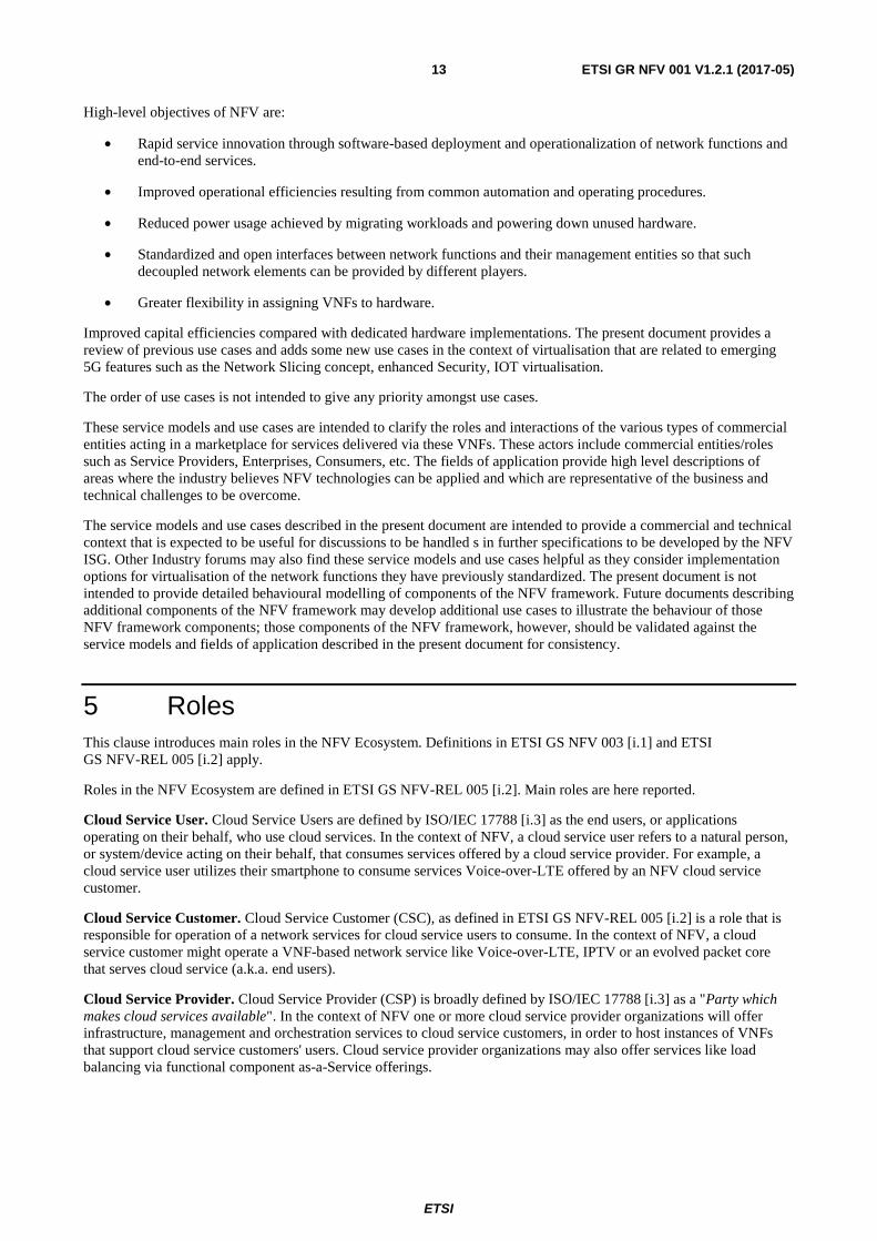
Service is a word with multiple meanings that are generally related to the act of doing something useful for another entity, often for a fee or as part of some commercial transaction [i.6], or as a functionality enabled by a service provider for the consumer of that service [i.7]; in the context of computing, software and service oriented networks. However, it can also refer to a function that is performed by software for another (software) entity [i.7]. The NFV Infrastructure can be considered as providing the capability or functionality of providing an environment in which Virtualised network functions can execute. This use case provides an approach to mapping the Cloud Computing Service Models IaaS and NaaS as elements within the Network Function Virtualisation Infrastructure when it is provided as a service.
Figure 1: Mapping IaaS and NaaS within the NFV Infrastructure
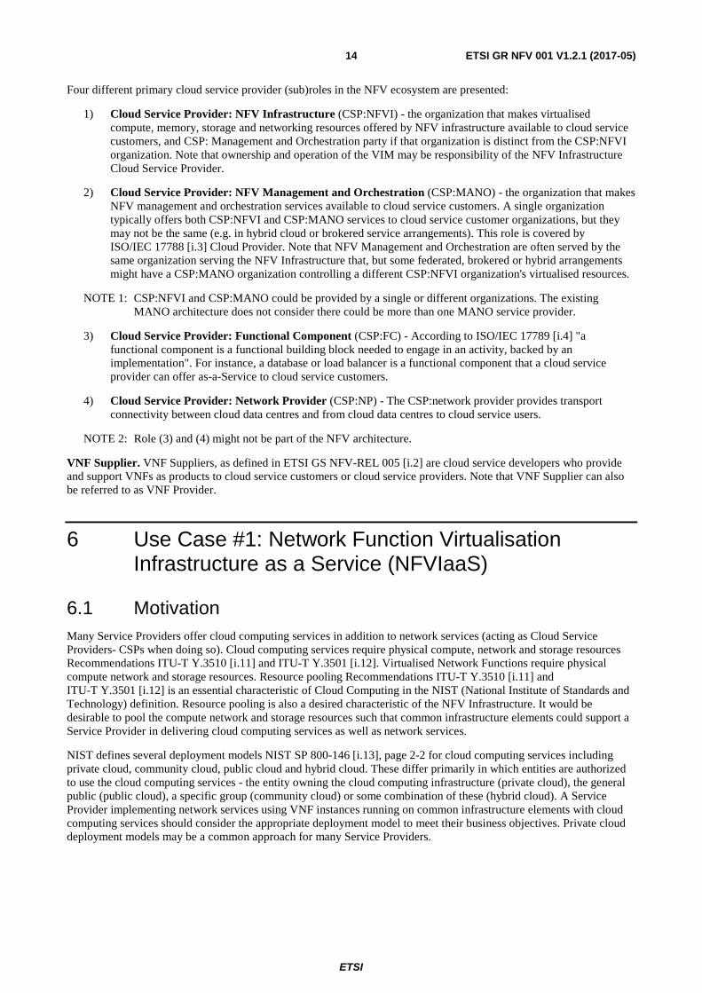
The resources to be pooled between these services are the physical network, storage and compute resources. In the NFV model these would be considered as the Compute, Hypervisor and Network domains of the Network Function Virtualisation Infrastructure. The computing nodes of the NFV Infrastructure will be located in NFVI-PoPs such as central offices, outside plant, specialized pods or embedded in other network equipment or mobile devices. The physical location of the infrastructure is largely irrelevant for cloud computing services, but many network services have some degree of location dependence. The resource pooling concept includes a notion of multi-tenancy - where the same pool of resources supports multiple applications from different administrative or trust domains. Figure 2 illustrates an NFVIaaS supporting both cloud computing applications as well as VNF instances from different administrative domains.
ETSI
ETSI GR NFV 001 V1.2.1 (2017-05)16
Figure 2: NFVIaaS Multi-tenant Support
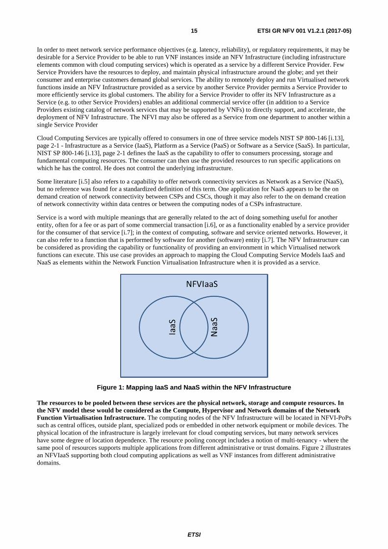
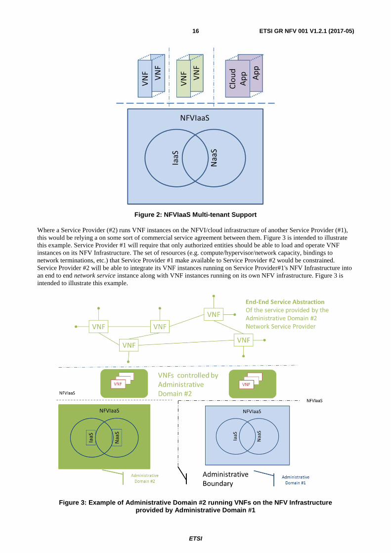
Where a Service Provider (#2) runs VNF instances on the NFVI/cloud infrastructure of another Service Provider (#1), this would be relying a on some sort of commercial service agreement between them. Figure 3 is intended to illustrate this example. Service Provider #1 will require that only authorized entities should be able to load and operate VNF instances on its NFV Infrastructure. The set of resources (e.g. compute/hypervisor/network capacity, bindings to network terminations, etc.) that Service Provider #1 make available to Service Provider #2 would be constrained. Service Provider #2 will be able to integrate its VNF instances running on Service Provider#1's NFV Infrastructure into an end to end network service instance along with VNF instances running on its own NFV infrastructure. Figure 3 is intended to illustrate this example.
Figure 3: Example of Administrative Domain #2 running VNFs on the NFV Infrastructure provided by Administrative Domain #1
ETSI
ETSI GR NFV 001 V1.2.1 (2017-05)17
6.2 Detailed User Story #1 - Compute Service Instantiation
6.2.1 Summary
As a Compute Service User, I use the NFVIaaS to instantiate/delete a network accessible compute instance so that it is available for my use.
6.2.2 Actor(s)
Compute Service User - the entity requesting use of a compute service.
NFVIaaS Service Provider - the entity providing the NFVIaaS service including the compute service.
6.2.3 Pre-Conditions
NFVIaaS Service Provider has deployed NFVI and offers the NFVIaaS including a compute service.
For this example the compute service instance is assumed provided by a virtual machine. Similar services may apply for other virtualisation mechanisms.
The Compute Service User has commercial arrangements providing authorization to create or delete compute instances.
6.2.4 Begins When
The Compute Service User requests that a compute instance (e.g. virtual Machine) be instantiated or deleted.
6.2.5 Description
1) The NFVI receives the compute service request for creation or deletion.
a) A creation request may include parameters for the compute instance, including location or affinity information.
b) A deletion request identifies the specific instance to be deleted.
2) The compute service user is authenticated and the authorization is validated by the NFVI.
3) The resource requirements to support the compute instance are checked. If sufficient resources are available, the compute instance is created.
4) The address and any other access rights to the instance or error code is returned to the compute service user.
6.2.6 End When
The response is returned to the compute service user.
6.2.7 Post-Conditions
The compute instance is created or deleted.
6.2.8 Exceptions
If compute service is not created/deleted an error code is returned to the compute service user.
Error codes should include lack of authorization, and lack of resources.
ETSI
ETSI GR NFV 001 V1.2.1 (2017-05)18
6.3 Detailed User Story #2 - Storage Service Instantiation
6.3.1 Summary
As a Storage Service User, I use the NFVIaaS to instantiate/delete a network accessible storage instance so that it is available for my use.
6.3.2 Actor(s)
Storage Service User - the entity requesting use of a storage service.
NFVIaaS Service Provider - the entity providing the NFVIaaS service including the compute service.
6.3.3 Pre-Conditions
NFVIaaS Service Provider has deployed NFVI and offers the NFVIaaS including a storage service.
The Storage Service User has commercial arrangements providing authorization to create or delete storage instances.
6.3.4 Begins When
The Storage Service User requests that a compute instance be instantiated or deleted.
6.3.5 Description
1) The NFVI receives the Storage service request for creation or deletion.
a) A creation request may include parameters for the storage instance, including location or affinity information.
b) A deletion request identifies the specific instance to be deleted.
2) The Storage Service User is authenticated and the authorization is validated by the NFVI.
3) The resource requirements to support the storage instance are checked. If sufficient resources are available, the storage instance is created.
4) The address and any other access rights to the instance or error code is returned to the storage service user.
6.3.6 End When
The response is returned to the storage service user.
6.3.7 Post-Conditions
Storage is allocated/deallocated to the storage service user.
6.3.8 Exceptions
If storage service is not created/deleted an error code is returned to the storage service user.
Error codes should include lack of authorization, and lack of resources.
ETSI
ETSI GR NFV 001 V1.2.1 (2017-05)19
6.4 Detailed User Story #3 - Network Service Instantiation
6.4.1 Summary
As a Network Service User, I use the NFVIaaS to instantiate/delete a network service between defined endpoints so that the service is available for my use.
6.4.2 Actor(s)
Network Service User - the entity requesting use of a NFVIaaS Network Service.
NFVIaaS Service Provider - the entity providing the NFVIaaS service including the Network Service.
6.4.3 Pre-Conditions
NFVIaaS Service Provider has deployed NFVI and offers the NFVIaaS including a network service.
The Network Service User has commercial arrangements providing authorization to create or delete Network Service instances.
The specific network services to be invoked are defined by the NFVIaaS Service Provider. Example NFVIaaS Network Services include layer 3 IP-VPN services and Layer 2 VPN services e.g. E-Line, E-LAN/E-Tree services.
Additional transactions may be required to validate that service can be provided to the endpoints requested.
6.4.4 Begins When
The Network Service User requests that a Network Service instance be instantiated or deleted.
6.4.5 Description
1) The NFVI receives the network service request for creation or deletion:
a) A creation request may include parameters for the network service instance, including endpoint location or affinity information.
b) A deletion request identifies the specific network service instance to be deleted.
2) The network Service User is authenticated and the authorization is validated by the NFVI.
3) The resource requirements to support the network service instance are checked. If sufficient resources are available, the network service instance is created.
4) The address and any other access rights to the instance or error code is returned to the network service user.
6.4.6 End When
The response is returned to the network service user.
6.4.7 Post-Conditions
The Network Service is created/deleted for the network service user.
6.4.8 Exceptions
If network service is not created/deleted an error code is returned to the network service user.
Error codes should include lack of authorization, and lack of resources.
ETSI
ETSI GR NFV 001 V1.2.1 (2017-05)20
6.5 Virtualisation Target
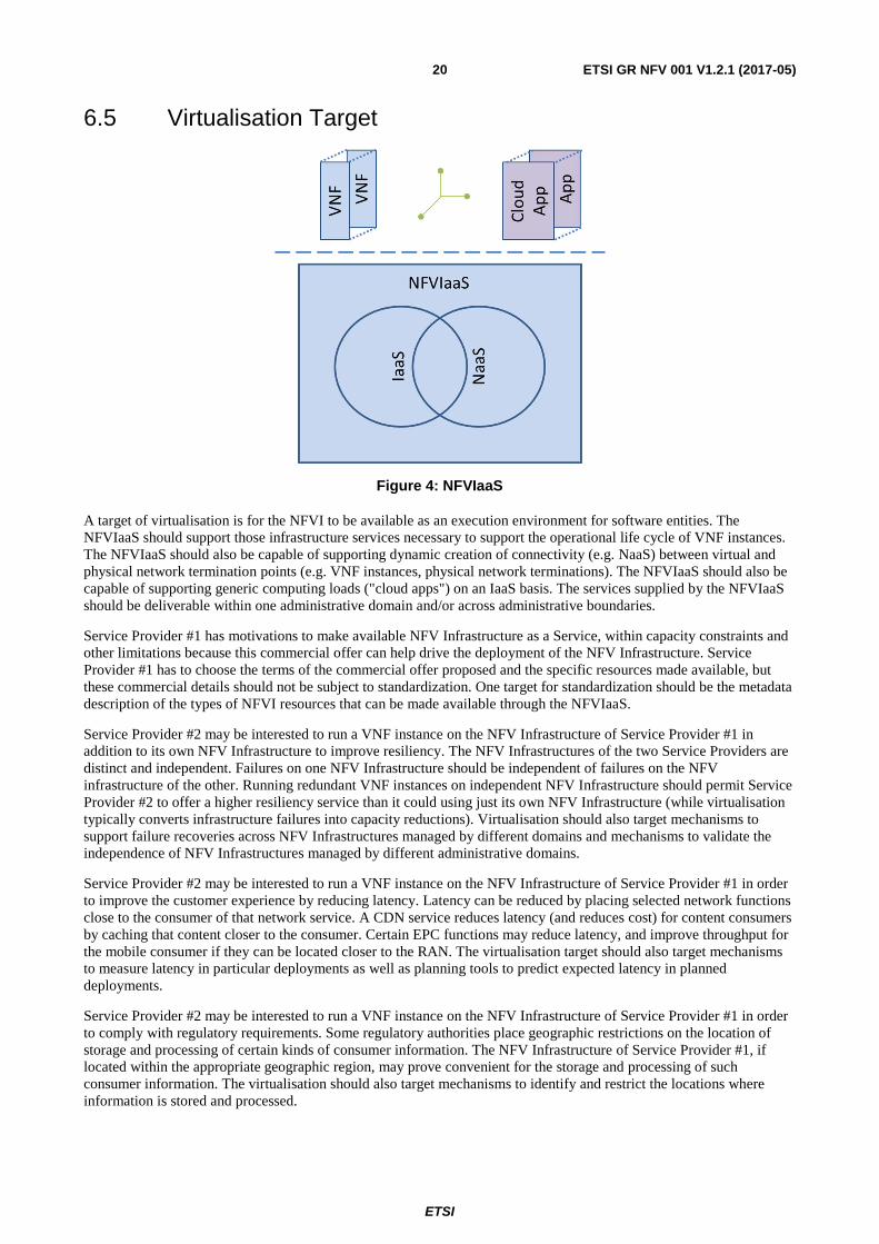
Figure 4: NFVIaaS
A target of virtualisation is for the NFVI to be available as an execution environment for software entities. The NFVIaaS should support those infrastructure services necessary to support the operational life cycle of VNF instances. The NFVIaaS should also be capable of supporting dynamic creation of connectivity (e.g. NaaS) between virtual and physical network termination points (e.g. VNF instances, physical network terminations). The NFVIaaS should also be capable of supporting generic computing loads ("cloud apps") on an IaaS basis. The services supplied by the NFVIaaS should be deliverable within one administrative domain and/or across administrative boundaries.
Service Provider #1 has motivations to make available NFV Infrastructure as a Service, within capacity constraints and other limitations because this commercial offer can help drive the deployment of the NFV Infrastructure. Service Provider #1 has to choose the terms of the commercial offer proposed and the specific resources made available, but these commercial details should not be subject to standardization. One target for standardization should be the metadata description of the types of NFVI resources that can be made available through the NFVIaaS.
Service Provider #2 may be interested to run a VNF instance on the NFV Infrastructure of Service Provider #1 in addition to its own NFV Infrastructure to improve resiliency. The NFV Infrastructures of the two Service Providers are distinct and independent. Failures on one NFV Infrastructure should be independent of failures on the NFV infrastructure of the other. Running redundant VNF instances on independent NFV Infrastructure should permit Service Provider #2 to offer a higher resiliency service than it could using just its own NFV Infrastructure (while virtualisation typically converts infrastructure failures into capacity reductions). Virtualisation should also target mechanisms to support failure recoveries across NFV Infrastructures managed by different domains and mechanisms to validate the independence of NFV Infrastructures managed by different administrative domains.
Service Provider #2 may be interested to run a VNF instance on the NFV Infrastructure of Service Provider #1 in order to improve the customer experience by reducing latency. Latency can be reduced by placing selected network functions close to the consumer of that network service. A CDN service reduces latency (and reduces cost) for content consumers by caching that content closer to the consumer. Certain EPC functions may reduce latency, and improve throughput for the mobile consumer if they can be located closer to the RAN. The virtualisation target should also target mechanisms to measure latency in particular deployments as well as planning tools to predict expected latency in planned deployments.
Service Provider #2 may be interested to run a VNF instance on the NFV Infrastructure of Service Provider #1 in order to comply with regulatory requirements. Some regulatory authorities place geographic restrictions on the location of storage and processing of certain kinds of consumer information. The NFV Infrastructure of Service Provider #1, if located within the appropriate geographic region, may prove convenient for the storage and processing of such consumer information. The virtualisation should also target mechanisms to identify and restrict the locations where information is stored and processed.
ETSI
ETSI GR NFV 001 V1.2.1 (2017-05)21
6.6 Coexistence of Virtualised and Non-Virtualised Network Functions
Non Virtualised network functions would exist in parallel with the VNFs in this use case, but are not expected to raise any issue particular to this use case.
Virtualised Network Functions from multiple Service Providers may coexist within the same NFV infrastructure. The NFV infrastructure is responsible for providing appropriate isolation between the resources allocated to the different service providers. VNF instances failures or resource demands from one service Provider should not be permitted to degrade the operation of other Service Provider's VNF instances.
There will be a need to implement IP, Ethernet and other packet forwarding mechanisms to interconnect to and manage VNF instances in another Service Provider's Infrastructure as well as connect to users connected to another Service Provider's access network.
6.7 Problem description/Issues
The NFVIaaS model should permit a Service Provider to fulfil, assure and bill for services delivered to end users across NFVIs that are independently administered, and therefore requires accurate monitoring and reporting of status of NFVI resources allocated to the VNF instances of a particular Service Provider. The management and orchestration of VNF instances into a network service instance through a VNF Forwarding Graph should be possible when the VNF instance is running on the NFV Infrastructure of another service provider. Appropriate authentication and authorization mechanism will be required to support orchestration of VNF instances in these cases. The NFVI should provide mechanisms to restrict access such that only authorized VNF instances are permitted to execute on the NFVI. The NFVI should provide mechanisms such that VNF instances can only access the physical and virtual network terminations to which their access is authorized.
Commercial NFVIaaS offers between Service Providers need to support both SLA measurement related parameters [i.1], and failure notification and diagnostics.
7 Use Case #2: VNF Forwarding Graphs
7.1 Motivation A Network Function (NF) Forwarding Graph [i.1] defines the sequence of NFs that packets traverse. A simple Network Service [i.1] can be implemented in an NFV environment using point to point links. This use case demonstrates that more complex structures might be necessary as VNF Forwarding Graph (VNF FG) [i.1].
VNF FGs are equivalent to connecting Physical Appliances via cables as described in the NFV white paper. Cables are bidirectional and so are most data networking technologies that will be used in Virtualised deployments in the near term (e.g. Ethernet). In other words, a VNF Forwarding Graph provides the logical connectivity between virtual appliances (i.e. VNFs).
To realize the goals of NFV, Service Providers need to develop Network Services at an abstract level and then deploy them in instantiations bound to particular NFVI resources (compute nodes, infrastructure networking termination points, existing physical NEs, etc.) These abstract definitions of Network Services are a subject for further study, however, an abstract Network Service based on VNFs seems likely to include identification of the types of VNFs involved, the relationships between these VNFs and the interconnection (forwarding) topology along with related management and dependency relationships. Of course, a VNF FG can also interconnect with Physical Network Functions to provide a Network Service.
VNF FGs solve the following problems and/or provide benefits as compared with a physical appliance based forwarding graphs.
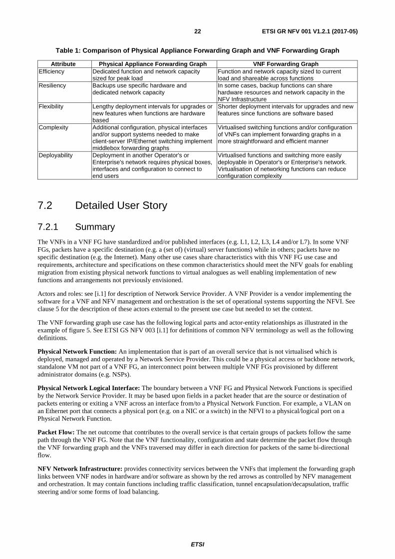
ETSI
ETSI GR NFV 001 V1.2.1 (2017-05)22
Table 1: Comparison of Physical Appliance Forwarding Graph and VNF Forwarding Graph
Attribute Physical Appliance Forwarding Graph VNF Forwarding Graph Efficiency Dedicated function and network capacity
sized for peak load Function and network capacity sized to current load and shareable across functions
Resiliency Backups use specific hardware and dedicated network capacity
In some cases, backup functions can share hardware resources and network capacity in the NFV Infrastructure
Flexibility Lengthy deployment intervals for upgrades or new features when functions are hardware based
Shorter deployment intervals for upgrades and new features since functions are software based
Complexity Additional configuration, physical interfaces and/or support systems needed to make client-server IP/Ethernet switching implement middlebox forwarding graphs
Virtualised switching functions and/or configuration of VNFs can implement forwarding graphs in a more straightforward and efficient manner
Deployability Deployment in another Operator's or Enterprise's network requires physical boxes, interfaces and configuration to connect to end users
Virtualised functions and switching more easily deployable in Operator's or Enterprise's network. Virtualisation of networking functions can reduce configuration complexity
7.2 Detailed User Story
7.2.1 Summary
The VNFs in a VNF FG have standardized and/or published interfaces (e.g. L1, L2, L3, L4 and/or L7). In some VNF FGs, packets have a specific destination (e.g. a (set of) (virtual) server functions) while in others; packets have no specific destination (e.g. the Internet). Many other use cases share characteristics with this VNF FG use case and requirements, architecture and specifications on these common characteristics should meet the NFV goals for enabling migration from existing physical network functions to virtual analogues as well enabling implementation of new functions and arrangements not previously envisioned.
Actors and roles: see [i.1] for description of Network Service Provider. A VNF Provider is a vendor implementing the software for a VNF and NFV management and orchestration is the set of operational systems supporting the NFVI. See clause 5 for the description of these actors external to the present use case but needed to set the context.
The VNF forwarding graph use case has the following logical parts and actor-entity relationships as illustrated in the example of figure 5. See ETSI GS NFV 003 [i.1] for definitions of common NFV terminology as well as the following definitions.
Physical Network Function: An implementation that is part of an overall service that is not virtualised which is deployed, managed and operated by a Network Service Provider. This could be a physical access or backbone network, standalone VM not part of a VNF FG, an interconnect point between multiple VNF FGs provisioned by different administrator domains (e.g. NSPs).
Physical Network Logical Interface: The boundary between a VNF FG and Physical Network Functions is specified by the Network Service Provider. It may be based upon fields in a packet header that are the source or destination of packets entering or exiting a VNF across an interface from/to a Physical Network Function. For example, a VLAN on an Ethernet port that connects a physical port (e.g. on a NIC or a switch) in the NFVI to a physical/logical port on a Physical Network Function.
Packet Flow: The net outcome that contributes to the overall service is that certain groups of packets follow the same path through the VNF FG. Note that the VNF functionality, configuration and state determine the packet flow through the VNF forwarding graph and the VNFs traversed may differ in each direction for packets of the same bi-directional flow.
NFV Network Infrastructure: provides connectivity services between the VNFs that implement the forwarding graph links between VNF nodes in hardware and/or software as shown by the red arrows as controlled by NFV management and orchestration. It may contain functions including traffic classification, tunnel encapsulation/decapsulation, traffic steering and/or some forms of load balancing.
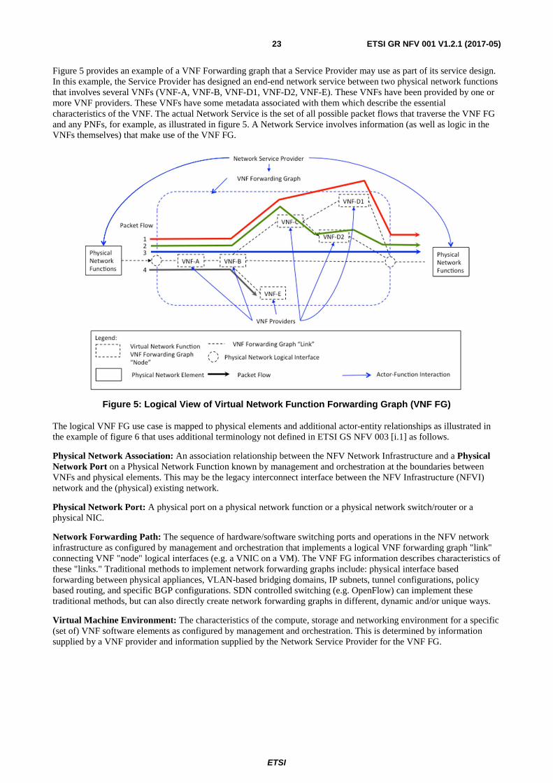
ETSI
ETSI GR NFV 001 V1.2.1 (2017-05)23
Figure 5 provides an example of a VNF Forwarding graph that a Service Provider may use as part of its service design. In this example, the Service Provider has designed an end-end network service between two physical network functions that involves several VNFs (VNF-A, VNF-B, VNF-D1, VNF-D2, VNF-E). These VNFs have been provided by one or more VNF providers. These VNFs have some metadata associated with them which describe the essential characteristics of the VNF. The actual Network Service is the set of all possible packet flows that traverse the VNF FG and any PNFs, for example, as illustrated in figure 5. A Network Service involves information (as well as logic in the VNFs themselves) that make use of the VNF FG.
Figure 5: Logical View of Virtual Network Function Forwarding Graph (VNF FG)
The logical VNF FG use case is mapped to physical elements and additional actor-entity relationships as illustrated in the example of figure 6 that uses additional terminology not defined in ETSI GS NFV 003 [i.1] as follows.
Physical Network Association: An association relationship between the NFV Network Infrastructure and a Physical Network Port on a Physical Network Function known by management and orchestration at the boundaries between VNFs and physical elements. This may be the legacy interconnect interface between the NFV Infrastructure (NFVI) network and the (physical) existing network.
Physical Network Port: A physical port on a physical network function or a physical network switch/router or a physical NIC.
Network Forwarding Path: The sequence of hardware/software switching ports and operations in the NFV network infrastructure as configured by management and orchestration that implements a logical VNF forwarding graph "link" connecting VNF "node" logical interfaces (e.g. a VNIC on a VM). The VNF FG information describes characteristics of these "links." Traditional methods to implement network forwarding graphs include: physical interface based forwarding between physical appliances, VLAN-based bridging domains, IP subnets, tunnel configurations, policy based routing, and specific BGP configurations. SDN controlled switching (e.g. OpenFlow) can implement these traditional methods, but can also directly create network forwarding graphs in different, dynamic and/or unique ways.
Virtual Machine Environment: The characteristics of the compute, storage and networking environment for a specific (set of) VNF software elements as configured by management and orchestration. This is determined by information supplied by a VNF provider and information supplied by the Network Service Provider for the VNF FG.
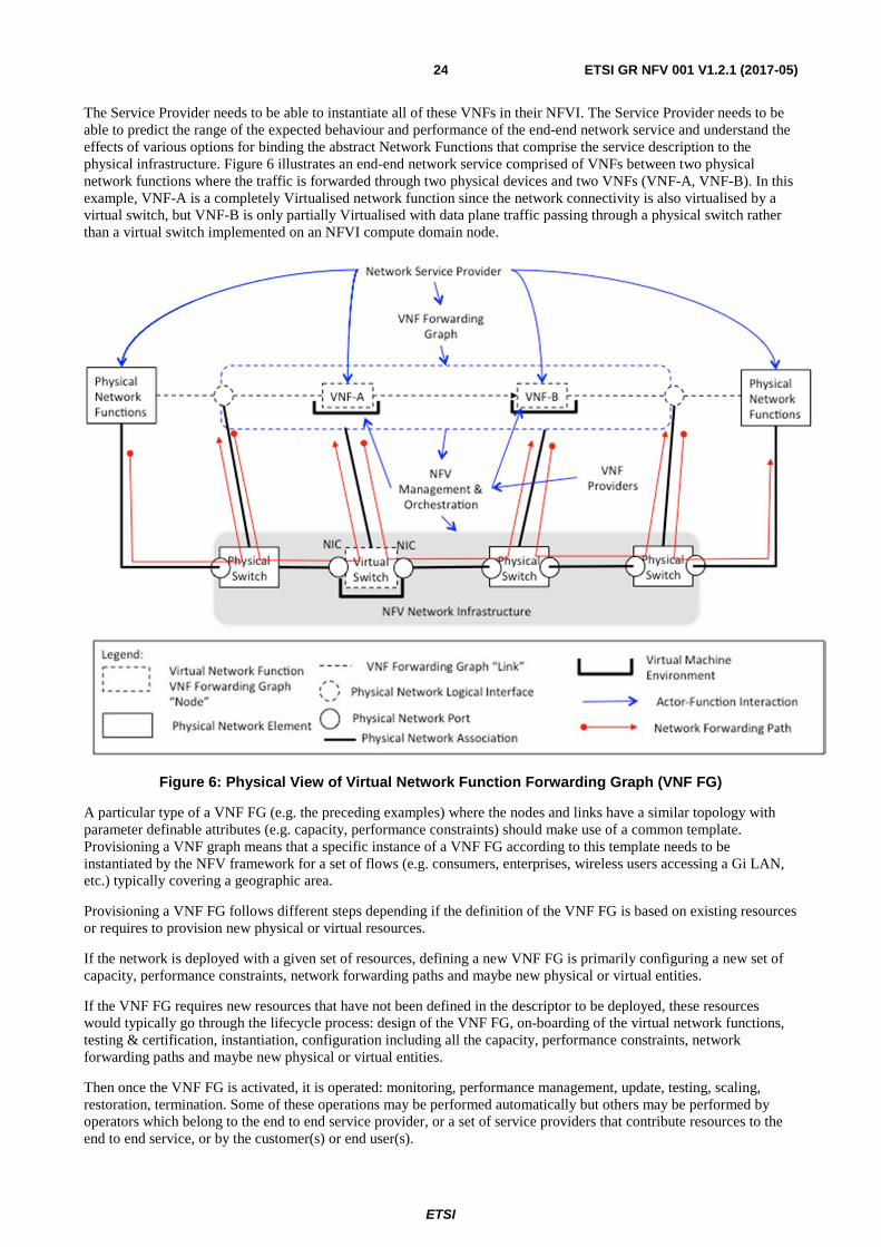
ETSI
ETSI GR NFV 001 V1.2.1 (2017-05)24
The Service Provider needs to be able to instantiate all of these VNFs in their NFVI. The Service Provider needs to be able to predict the range of the expected behaviour and performance of the end-end network service and understand the effects of various options for binding the abstract Network Functions that comprise the service description to the physical infrastructure. Figure 6 illustrates an end-end network service comprised of VNFs between two physical network functions where the traffic is forwarded through two physical devices and two VNFs (VNF-A, VNF-B). In this example, VNF-A is a completely Virtualised network function since the network connectivity is also virtualised by a virtual switch, but VNF-B is only partially Virtualised with data plane traffic passing through a physical switch rather than a virtual switch implemented on an NFVI compute domain node.
Figure 6: Physical View of Virtual Network Function Forwarding Graph (VNF FG)
A particular type of a VNF FG (e.g. the preceding examples) where the nodes and links have a similar topology with parameter definable attributes (e.g. capacity, performance constraints) should make use of a common template. Provisioning a VNF graph means that a specific instance of a VNF FG according to this template needs to be instantiated by the NFV framework for a set of flows (e.g. consumers, enterprises, wireless users accessing a Gi LAN, etc.) typically covering a geographic area.
Provisioning a VNF FG follows different steps depending if the definition of the VNF FG is based on existing resources or requires to provision new physical or virtual resources.
If the network is deployed with a given set of resources, defining a new VNF FG is primarily configuring a new set of capacity, performance constraints, network forwarding paths and maybe new physical or virtual entities.
If the VNF FG requires new resources that have not been defined in the descriptor to be deployed, these resources would typically go through the lifecycle process: design of the VNF FG, on-boarding of the virtual network functions, testing & certification, instantiation, configuration including all the capacity, performance constraints, network forwarding paths and maybe new physical or virtual entities.
Then once the VNF FG is activated, it is operated: monitoring, performance management, update, testing, scaling, restoration, termination. Some of these operations may be performed automatically but others may be performed by operators which belong to the end to end service provider, or a set of service providers that contribute resources to the end to end service, or by the customer(s) or end user(s).
ETSI
ETSI GR NFV 001 V1.2.1 (2017-05)25
When a Network Service related with VNF FG is provisioned, the NFV Framework needs to keep a record of the Infrastructure resources that are used so that future operational processes (such as localization of a fault, restoration, resizing or termination of the service) can be undertaken on all relevant objects in the VNF FG.
An example of a VNF FG commonly encountered is where packets traverse a VNF implementation of a router, an intrusion detection device, a firewall NAT, and a load balancer that distributes traffic to a pool of servers. One deployment example is a subscriber-oriented service for wireless users deployed at a NFVI-PoP on a wireless Gi LAN or in a wireline network.
7.2.2 Actor(s)
Actors external to this use case (business needs) but needed to set the context:
• Customer - the entity that requests the end to end service that drives the need for a VNF FG. The request is sent to the network service provider.
• Service Provider -defined as a company or organization, making use of an electronics communications network or part thereof to provide a service or services on a commercial basis to third parties (as defined in ETSI GS NFV 003 [i.1]).
• NFVO Provider - the company or organization or entity that offers the management and orchestration of VNF FG.
• VNF Provider - the company or organization or entity that offers the VNF.
• PNF Provider -the company or organization or entity that offers the PNF.
• NFV Network Provider - the company or organization or entity that offers the implement of forwarding graph links.
• End User - the entity that uses the service delivered by the VNF FG.
7.2.3 Pre-Conditions
The following pre-conditions apply:
• There has been a Customer request for an end to end service that drives the need for a VNF FG.
• The service provider has decomposed the request and has identified the required VNF FG.
• VNF FG descriptors have been prepared. The nodes and links of VNF/PNF required have been on-boarded in the different NFVOs.
• Any referenced descriptors of CPs, VLs,VNFs or PNFs in the VNF FG instantiation request have already be on-boarded.
• NFVI network resources that support the VNF FG are available from the end to end.
7.2.4 Begins When
The use case covering the lifecycle of the VNF FG.
The use case begins when the Service Provider requests a new VNF FG instance to serve that end user. This request is from an OSS that has an end to end view on the potentially dynamic topology and can access to the different NFVOs that manage the forwarding paths of the required VNF FG to either configure or request configuration of these forwarding paths with proper access rights, policies to this new VNF FG instance.
ETSI
ETSI GR NFV 001 V1.2.1 (2017-05)26
7.2.5 Description
The environment around a VNF FG may vary depending on different VNFs or PNFs but the most common cases are:
• NFVO that will receive VNF FG request with the associated VNFFG that will describe what is expected in terms of the VNFFG: NFPs, referenced VLs, VNFs, PNFs and cpdpool.
• NFVO will interpret the descriptor, generate the different network forwarding paths based on vary rules and request VIM to create these forwarding paths to implement the connectivity services.
• NFVO may also store the descriptors, but also information specific to the VNF FG instance, but also may trigger some lifecycles functions: update the VNF FG, remove a VNF FG, etc.
7.2.6 End When
When the Service Provider request that the service does not need this VNF FG anymore, the VNF FG may be removed and the VNF FG related logical and physical resources will be released.
7.2.7 Post-Conditions
When the VNF FG is removed, the logical and physical resources only used by that VNF FG are freed up.
7.2.8 Exceptions
Upon certain exceptions, example network crash, the VNF FG may release some logical resources. But this is an exception that is temporary.
7.2.9 Virtualisation Target
The virtualisation target requires the following capabilities in support of a VNF FG:
1) An information model that enables a Network Service Provider to describe to management and Orchestration entities the characteristics of nodes and links of a VNF FG in terms of capacity, performance, resiliency, constraints, security, required virtual compute/networking environment requirements and other parameters.
2) An information model supplied by the VNF Provider that describes the NFVI resources needed to map an individual VNF instance (e.g. image running on a VM) to NFVI resources (e.g. virtual compute, storage and networking).
3) The Network Service Provider needs to be able to specify a mapping from the VNF FG that determines the selection and configuration of physical and/or virtual switching elements in the NFVI that are controlled via traditional and/or SDN methods.
4) An information model that allows a Network Service Provider to specify logical and physical interconnect points between the NFVI and Physical network functions, which may be interconnect points to other administrative domains (e.g. another operator) or VNF FG s, such that these can be implemented and managed by NFV management and orchestration. L1, L2 and/or L3 physical and/or virtualised L2/L3 networking environments.
5) The Network Service Provider needs to be able to identify the VNF FGs that are mapped to NFVI resources (e.g. compute domain nodes, hypervisor domain resources, infrastructure networking resources including physical links and physical network elements).
ETSI
ETSI GR NFV 001 V1.2.1 (2017-05)27
7.3 Coexistence of Virtualised and Non-Virtualised Network Functions
Coexistence, interoperation, migration, and interaction between physical/virtual network functions is applicable to this use case in the following areas:
• Interfaces provided by NFVI between a VNF Forwarding Graph and a physical network function or a physical network switch as configured and managed by NFV management and orchestration.
• Interfaces between, configuration and control plane interoperability between a physical switch and a virtual switch as provided by NFVI and managed by NFV management and orchestration.
• EMS, OSS, and/or BSS interfaces to physical/virtual function control and management augmented by any additional information exchange methods needed by NFV management and orchestration.
• Support by NFVI and NFV management and orchestration for migration from a physical network function to a virtual network function (or vice versa).
• Support by NFVI and NFV management and orchestration for interaction for control/management plane interoperability for physical network logical associations and physical ports (e.g. VLANs, tunnel, SDN configurations).
7.4 Problem description/Issues The challenges of the VNF Forwarding Graph (VNF FG) use case are driven primarily by the information model and its usage in achieving the virtualisation target as previously described. In this context, the following are specific challenges:
• Specifying attributes of a VNF FG as supplied by a Network Service Provider such that the required overall performance, capacity, and resiliency is achieved. Measurement methods to validate that these are achieved may be needed.
• Specifying attributes supplied by a VNF provider such that each VNF's contribution to the overall performance, capacity and resiliency of the VNF FG is achieved. Measurement, testing, and/or validation methods to validate that these are achieved may be needed.
• VNF FG interconnection selection by the Network Service Provider from a broad set of networking alternatives such that acceptable efficiency results and that the requirement networking capacity, performance and resiliency is achieved.
• Network Service Providers need to support end-end services that cross administrative boundaries, hence aspects involving multiple administrative domains in terms of operation, interworking, and migration to/from physical network function implementations need to be further described.
• The abstract end-end network service will require further definition of additional relationships between the VNFs that comprise the service. The definition of the service and the identification of the categories of relationships need further study to facilitate service creation using VNFs by cooperating Network Service Providers.
• Resources need to be assigned to implement the "nodes" and "links" of a VNF FG initially in response to an operator provisioning request. The assignment of resources that implement "nodes" and "links. May need to be modified in response to load changes and/or a catastrophic failure in the event that other mechanisms do not adjust capacity or restore the forwarding graph resources.
ETSI
ETSI GR NFV 001 V1.2.1 (2017-05)28
8 Use Case #3: Virtualisation of Mobile Core Network and IMS
8.1 Motivation Mobile networks are populated with a large variety of proprietary hardware appliances. Network Functions Virtualisation aims at reducing the network complexity and related operational issues by leveraging standard IT virtualisation technologies to consolidate different types of network equipment onto industry standard high volume servers, switches and storage, located in NFVI-PoPs. Such consolidation of hardware is expected to reduce Total Cost of Ownership (TCO). Flexible allocation of Network Functions on such hardware resource pool could highly improve network usage efficiency in day-to-day network operation. This also helps to accommodate increased demand for particular services (e.g. voice) without fully relying on the call restriction control mechanisms in a large-scale natural disaster scenario such as the Great East Japan Earthquake, during which mobile networks faced a massive number of call attempts for voice communication because most people urgently tried to confirm the safety of their family, friends, etc. Possible advantages of the virtualisation of mobile core network and IMS include the following:
• Reduced TCO.
• Improved network usage efficiency due to flexible allocation of different Network Functions on such hardware resource pool.
• Higher service availability and resiliency provided to end users/customers by dynamic network reconfiguration inherent to virtualisation technology.
• Elasticity: Capacity dedicated to each Network function can be dynamically modified according to actual load on the network, thus increasing scalability.
• Topology reconfiguration: Network topology can be dynamically reconfigured to optimize performances and to support agile introduction of new services.
In addition, Network Function Virtualisation enables the creation of a competitive environment where innovative implementations of 3rd party network applications can be supplied by unlocking the proprietary boundaries of current Mobile Core and IMS implementations.
8.2 Detailed User Story
8.2.1 Summary
This use case entails the capabilities that a virtual mobile network would provide to Network Providers to address customer's requests and associated network capacity demands.
NOTE: For simplicity, the user story entails vEPC lifecycle management aspects, but similar considerations can be made for vIMS.
8.2.2 Actor(s)
Actors related to this use case are:
• End Users acting as Cloud Service Users with respect to clause 5 definitions: they request access to mobile network services.
• Network Operator acting as Cloud Service Provider with respect to clause 5 definitions: provides mobile network services to end users through vEPC and vIMS. The network provider also operates orchestration platforms to control the scaling of the virtual network functions and network services.

ETSI
ETSI GR NFV 001 V1.2.1 (2017-05)29
8.2.3 Pre-Conditions
Network operator has created a vEPC and vIMS instances after on boarding corresponding Network Service descriptors and constituent VNF packages. A determined amount of virtual resources are assigned to the vEPC.
8.2.4 Begins When
The use case begins when mobile network capacity is being exhausted due to increase of end users requesting mobile network services. The core network connectivity for the mobile network service is provided by the vEPC.
8.2.5 Description
The use case is composed by the following steps:
1) The Network operator's orchestration platform detects a resource shortage on vEPC network functions.
2) The Network operator's orchestration platform expands the capacity of the vEPC. This results in the allocation of more resources to the vEPC.
3) End users continue to connect to mobile network without noticing any congestion on the network.
8.2.6 End When
The use case ends when the mobile network capacity is under-utilized due to users leaving the mobile network. The Network operator's orchestration platform decreases capacity of the vEPC, which results in the termination or scaling down of resources dedicated to the vEPC.
8.2.7 Post-Conditions
The users are disconnected from the mobile network. vEPC resource consumption is detected to be back to initial usage.
8.2.8 Exceptions
The following exceptions have been identified:
• Insufficient resources to support requested connections and/or scaling operations.
8.2.9 Virtualisation Target
The following network functions need to be virtualised as part of this use case:
1) Mobile Core Network Functions:
- EPC Core and Adjunct Network Functions e.g. MME, S/P-GW, PCRF, etc.
- 3G/EPC Interworking Network Functions e.g. SGSN, GGSN, etc.
- All IMS Network Functions e.g. P/S/I-CSCF, MGCF, AS.
It is important that the varying functional characteristics of the above NFs be considered in the NFV effort.
8.3 Coexistence of Virtualised and Non-Virtualised Network Functions
NFV-based Virtualised mobile core network will coexist with non-Virtualised mobile core network (figure 7), as the mobile core networks already deployed are not based on NFV. Network operators should have the freedom to choose the NFV deployment according to their desired migration plan from non-Virtualised network to NFV-based Virtualised network.
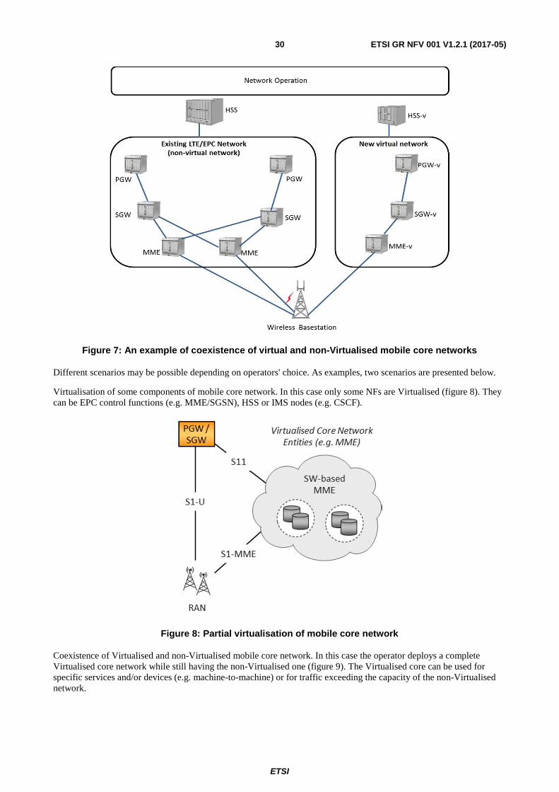
ETSI
ETSI GR NFV 001 V1.2.1 (2017-05)30
Figure 7: An example of coexistence of virtual and non-Virtualised mobile core networks
Different scenarios may be possible depending on operators' choice. As examples, two scenarios are presented below.
Virtualisation of some components of mobile core network. In this case only some NFs are Virtualised (figure 8). They can be EPC control functions (e.g. MME/SGSN), HSS or IMS nodes (e.g. CSCF).
Figure 8: Partial virtualisation of mobile core network
Coexistence of Virtualised and non-Virtualised mobile core network. In this case the operator deploys a complete Virtualised core network while still having the non-Virtualised one (figure 9). The Virtualised core can be used for specific services and/or devices (e.g. machine-to-machine) or for traffic exceeding the capacity of the non-Virtualised network.
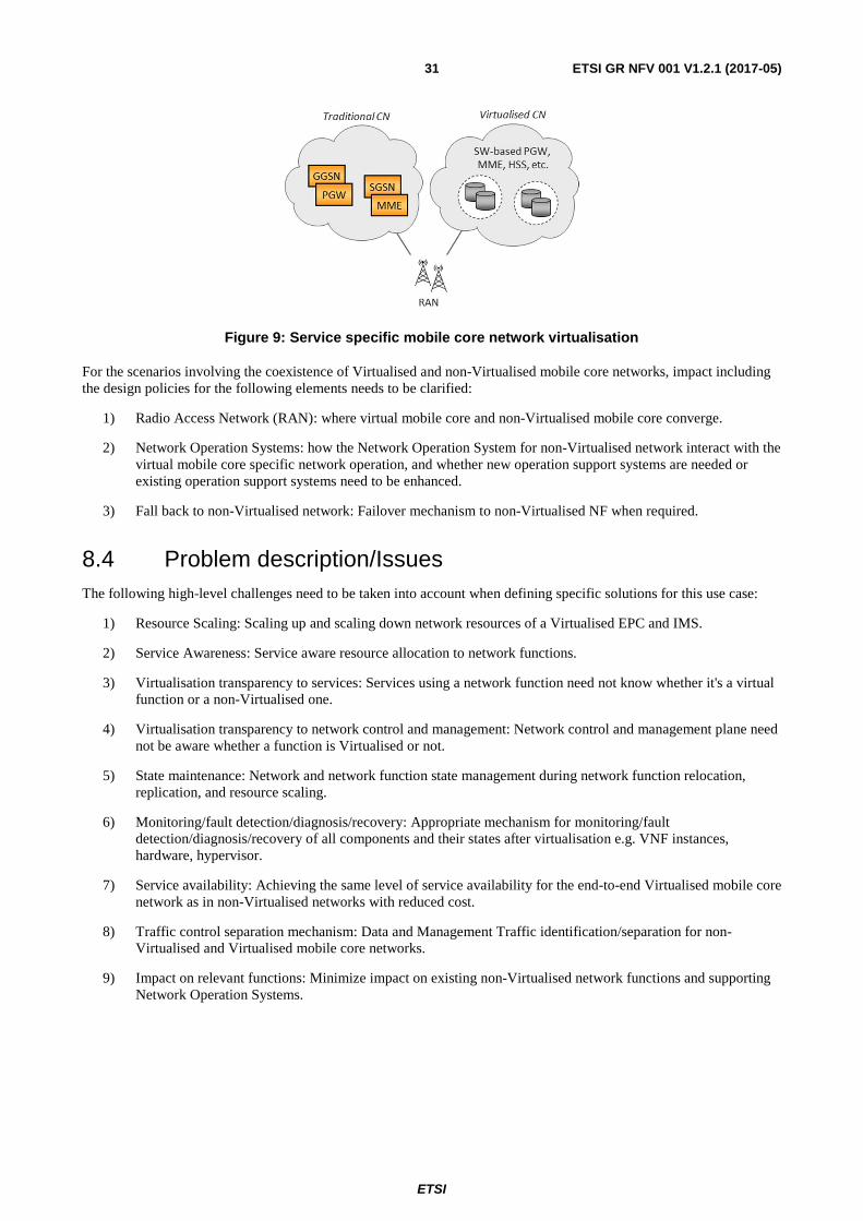
ETSI
ETSI GR NFV 001 V1.2.1 (2017-05)31
Figure 9: Service specific mobile core network virtualisation
For the scenarios involving the coexistence of Virtualised and non-Virtualised mobile core networks, impact including the design policies for the following elements needs to be clarified:
1) Radio Access Network (RAN): where virtual mobile core and non-Virtualised mobile core converge.
2) Network Operation Systems: how the Network Operation System for non-Virtualised network interact with the virtual mobile core specific network operation, and whether new operation support systems are needed or existing operation support systems need to be enhanced.
3) Fall back to non-Virtualised network: Failover mechanism to non-Virtualised NF when required.
8.4 Problem description/Issues The following high-level challenges need to be taken into account when defining specific solutions for this use case:
1) Resource Scaling: Scaling up and scaling down network resources of a Virtualised EPC and IMS.
2) Service Awareness: Service aware resource allocation to network functions.
3) Virtualisation transparency to services: Services using a network function need not know whether it's a virtual function or a non-Virtualised one.
4) Virtualisation transparency to network control and management: Network control and management plane need not be aware whether a function is Virtualised or not.
5) State maintenance: Network and network function state management during network function relocation, replication, and resource scaling.
6) Monitoring/fault detection/diagnosis/recovery: Appropriate mechanism for monitoring/fault detection/diagnosis/recovery of all components and their states after virtualisation e.g. VNF instances, hardware, hypervisor.
7) Service availability: Achieving the same level of service availability for the end-to-end Virtualised mobile core network as in non-Virtualised networks with reduced cost.
8) Traffic control separation mechanism: Data and Management Traffic identification/separation for non-Virtualised and Virtualised mobile core networks.
9) Impact on relevant functions: Minimize impact on existing non-Virtualised network functions and supporting Network Operation Systems.
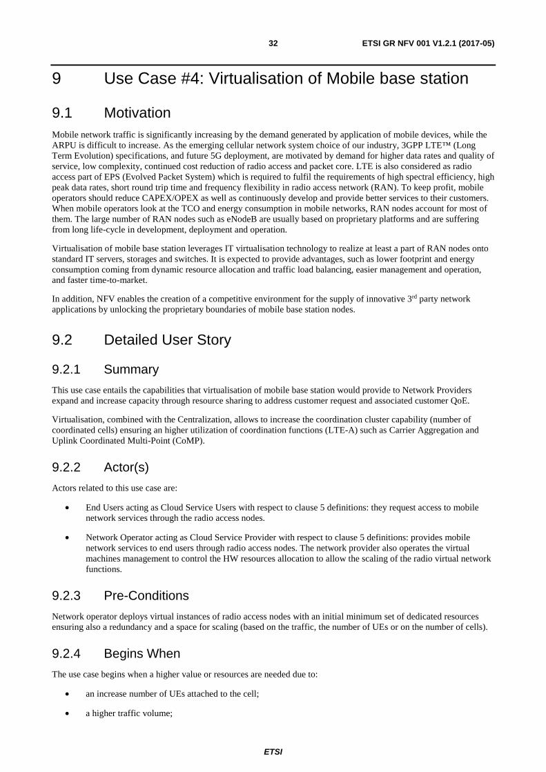
ETSI
ETSI GR NFV 001 V1.2.1 (2017-05)32
9 Use Case #4: Virtualisation of Mobile base station
9.1 Motivation Mobile network traffic is significantly increasing by the demand generated by application of mobile devices, while the ARPU is difficult to increase. As the emerging cellular network system choice of our industry, 3GPP LTE™ (Long Term Evolution) specifications, and future 5G deployment, are motivated by demand for higher data rates and quality of service, low complexity, continued cost reduction of radio access and packet core. LTE is also considered as radio access part of EPS (Evolved Packet System) which is required to fulfil the requirements of high spectral efficiency, high peak data rates, short round trip time and frequency flexibility in radio access network (RAN). To keep profit, mobile operators should reduce CAPEX/OPEX as well as continuously develop and provide better services to their customers. When mobile operators look at the TCO and energy consumption in mobile networks, RAN nodes account for most of them. The large number of RAN nodes such as eNodeB are usually based on proprietary platforms and are suffering from long life-cycle in development, deployment and operation.
Virtualisation of mobile base station leverages IT virtualisation technology to realize at least a part of RAN nodes onto standard IT servers, storages and switches. It is expected to provide advantages, such as lower footprint and energy consumption coming from dynamic resource allocation and traffic load balancing, easier management and operation, and faster time-to-market.
In addition, NFV enables the creation of a competitive environment for the supply of innovative 3rd party network applications by unlocking the proprietary boundaries of mobile base station nodes.
9.2 Detailed User Story
9.2.1 Summary
This use case entails the capabilities that virtualisation of mobile base station would provide to Network Providers expand and increase capacity through resource sharing to address customer request and associated customer QoE.
Virtualisation, combined with the Centralization, allows to increase the coordination cluster capability (number of coordinated cells) ensuring an higher utilization of coordination functions (LTE-A) such as Carrier Aggregation and Uplink Coordinated Multi-Point (CoMP).
9.2.2 Actor(s)
Actors related to this use case are:
• End Users acting as Cloud Service Users with respect to clause 5 definitions: they request access to mobile network services through the radio access nodes.
• Network Operator acting as Cloud Service Provider with respect to clause 5 definitions: provides mobile network services to end users through radio access nodes. The network provider also operates the virtual machines management to control the HW resources allocation to allow the scaling of the radio virtual network functions.
9.2.3 Pre-Conditions
Network operator deploys virtual instances of radio access nodes with an initial minimum set of dedicated resources ensuring also a redundancy and a space for scaling (based on the traffic, the number of UEs or on the number of cells).
9.2.4 Begins When
The use case begins when a higher value or resources are needed due to:
• an increase number of UEs attached to the cell;
• a higher traffic volume;
ETSI
ETSI GR NFV 001 V1.2.1 (2017-05)33
• a new cell deployment is needed.
The above mentioned operations depend on the chosen algorithm and on the thresholds chosen by the Operator.
9.2.5 Description
The use case is composed by the following steps:
1) The Network operator's management platform detects a HW resource congestion.
2) The Network operator's management platform expands the number of used resources creating new VM (scale out).
3) End users continue the mobile session without noticing any congestion on the network and without QoE degradation.
9.2.6 End When
The use case ends when the mobile network capacity is under-utilized due to users leaving the mobile network or a traffic reduction. The Network operator's management platform adapts the HW resources utilization to the needs (scale in).
9.2.7 Post-Conditions
The unused resources have been released and are available for new purposes, e.g. cell in a different place that need resources.
9.2.8 Exceptions
The following exceptions have been identified:
• Insufficient resources to support requested connections and/or scaling operations.
• Resources unavailable for redundancy.
9.2.9 Virtualisation Target
The present document focuses on LTE and LTE-Advanced based on C-RAN architecture (figure 10), however 2G, 3G, WiMAX® and other mobile network systems should be virtualised in a similar manner.
1) For Traditional RAN node such as eNodeB, Home eNodeB, and Femto/Picocell, possible virtualisation targets are baseband radio processing unit, MAC, RLC, PDCP, RRC (Radio Resource Control), Control and CoMP.
2) For C-RAN the above functions are considered in BBU, Switching function and Load balancer.
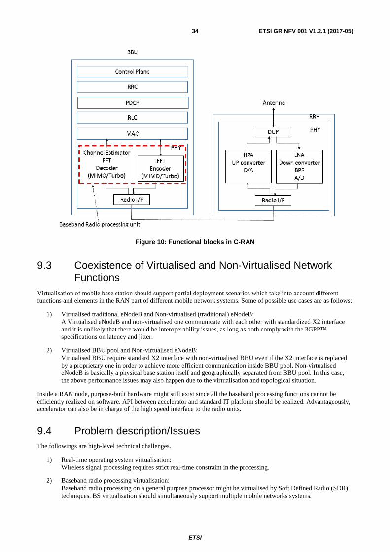
ETSI
ETSI GR NFV 001 V1.2.1 (2017-05)34
Figure 10: Functional blocks in C-RAN
9.3 Coexistence of Virtualised and Non-Virtualised Network Functions
Virtualisation of mobile base station should support partial deployment scenarios which take into account different functions and elements in the RAN part of different mobile network systems. Some of possible use cases are as follows:
1) Virtualised traditional eNodeB and Non-virtualised (traditional) eNodeB: A Virtualised eNodeB and non-virtualised one communicate with each other with standardized X2 interface and it is unlikely that there would be interoperability issues, as long as both comply with the 3GPP™ specifications on latency and jitter.
2) Virtualised BBU pool and Non-virtualised eNodeB: Virtualised BBU require standard X2 interface with non-virtualised BBU even if the X2 interface is replaced by a proprietary one in order to achieve more efficient communication inside BBU pool. Non-virtualised eNodeB is basically a physical base station itself and geographically separated from BBU pool. In this case, the above performance issues may also happen due to the virtualisation and topological situation.
Inside a RAN node, purpose-built hardware might still exist since all the baseband processing functions cannot be efficiently realized on software. API between accelerator and standard IT platform should be realized. Advantageously, accelerator can also be in charge of the high speed interface to the radio units.
9.4 Problem description/Issues The followings are high-level technical challenges.
1) Real-time operating system virtualisation: Wireless signal processing requires strict real-time constraint in the processing.
2) Baseband radio processing virtualisation: Baseband radio processing on a general purpose processor might be virtualised by Soft Defined Radio (SDR) techniques. BS virtualisation should simultaneously support multiple mobile networks systems.
ETSI
ETSI GR NFV 001 V1.2.1 (2017-05)35
3) Dynamic allocation of the processing resources: Within a physical BS virtualising multiple logical RAN nodes from different mobile network systems, the processing resources should be dynamically allocated to a higher load logical RAN node, so that real-time scheduling and strict processing delay and jitter requirements are met. BBU resources in C-RAN BBU pool are also required to scale according to the whole load of BBU pool. These might require northbound interface to virtualisation orchestrator in order to manage life-cycle event of virtualised processing resources.
4) Inter-connection within virtualised BBU pool: BBU pool require high bandwidth and low latency switching function with necessary data formats and protocols to inter-connect among multiple BBUs. With this switching function, BBU pool can realize the processing load balancing.
5) I/O virtualisation: I/O virtualisation or API between PHY layer accelerator and standard IT platform should be addressed to access. Especially for C-RAN, higher consolidation of RRHs to a BBU pool with higher I/O can benefit from higher statistical multiplexing effect.
6) Handover performance: X2 U-plane handover latency might be affected under the X2 interface between two virtualised eNodeBs, or between virtualised eNodeB and non-virtualised eNodeB, due to the physical distance between virtualised/non-virtualised eNodeBs.
10 Use Case #5: Virtualisation of the Home Environment
10.1 Motivation Current network operator provided home services are architected using network-located backend systems and dedicated CPE devices located as part of the home network. These CPE devices mark the operator and/or service provider presence at the customer premises and usually include a Residential Gateway (RGW) for Internet and VOIP services, and a Setup Box (STB) for Media services normally supporting local storage for PVR services. In some countries, regulatory restrictions are in place for network based PVR and these will need to be addressed accordingly.
NFV technologies enable flexible evolution of the home environment by reducing hardware-specific functionality with minimal cost and improved Time To Market, and new services can be introduced as required on a grow-as-you-need basis. The benefits derived from avoiding installation of new equipment would be amplified if evolution of the home environment is considered with the appropriate NFV approach.
The availability of high bandwidth access (such as offered by Fibre) and the emergence of NFV technology facilitate virtualisation of the home environment, requiring only simple, physical connectivity and focused, low cost, and low maintenance (physical) devices at the customer premises.
While this new architecture may increase the demand for bandwidth between the home and the network, advantages to the operator and the end customer are significant:
• CAPEX reduction by eliminating the costly STB (one per TV) and RGW.
• OPEX reduction by eliminating the need to constantly maintain and upgrade the CPEs. And capacities to make remote diagnostic of the user devices in order to provide direct solutions to the problems in the user network.
• Improved QoE by functionality such as remote access to all content and services, multi-screen support and mobility.
• New service introduction is smooth and less cumbersome as the dependency on the physical CPE at the customer premises functionality and user installation processes is minimized.
• Improved security through application of terminal-specific (e.g. tablet, STB, IoT) policies, and/or user-specific policies (e.g. parental controls) as well as counter-measures such as network-based firewall and isolating compromised home environment devices.
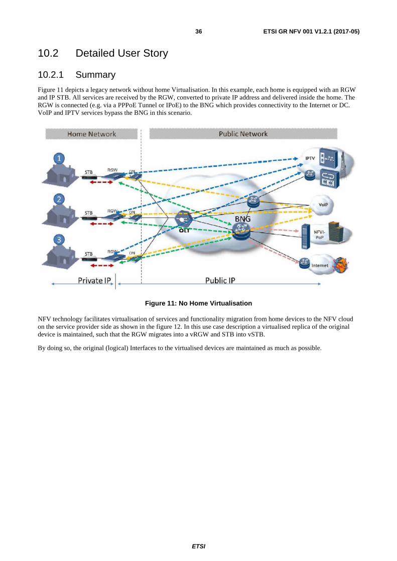
ETSI
ETSI GR NFV 001 V1.2.1 (2017-05)36
10.2 Detailed User Story
10.2.1 Summary
Figure 11 depicts a legacy network without home Virtualisation. In this example, each home is equipped with an RGW and IP STB. All services are received by the RGW, converted to private IP address and delivered inside the home. The RGW is connected (e.g. via a PPPoE Tunnel or IPoE) to the BNG which provides connectivity to the Internet or DC. VoIP and IPTV services bypass the BNG in this scenario.
Figure 11: No Home Virtualisation
NFV technology facilitates virtualisation of services and functionality migration from home devices to the NFV cloud on the service provider side as shown in the figure 12. In this use case description a virtualised replica of the original device is maintained, such that the RGW migrates into a vRGW and STB into vSTB.
By doing so, the original (logical) Interfaces to the virtualised devices are maintained as much as possible.
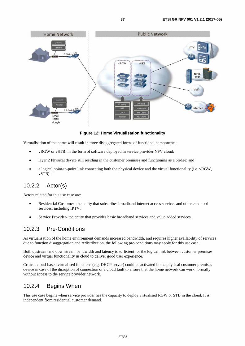
ETSI
ETSI GR NFV 001 V1.2.1 (2017-05)37
Figure 12: Home Virtualisation functionality
Virtualisation of the home will result in three disaggregated forms of functional components:
• vRGW or vSTB: in the form of software deployed in service provider NFV cloud;
• layer 2 Physical device still residing in the customer premises and functioning as a bridge; and
• a logical point-to-point link connecting both the physical device and the virtual functionality (i.e. vRGW, vSTB).
10.2.2 Actor(s)
Actors related for this use case are:
• Residential Customer- the entity that subscribes broadband internet access services and other enhanced services, including IPTV.
• Service Provider- the entity that provides basic broadband services and value added services.
10.2.3 Pre-Conditions
As virtualisation of the home environment demands increased bandwidth, and requires higher availability of services due to function disaggregation and redistribution, the following pre-conditions may apply for this use case.
Both upstream and downstream bandwidth and latency is sufficient for the logical link between customer premises device and virtual functionality in cloud to deliver good user experience.
Critical cloud-based virtualised functions (e.g. DHCP server) could be activated in the physical customer premises device in case of the disruption of connection or a cloud fault to ensure that the home network can work normally without access to the service provider network.
10.2.4 Begins When
This use case begins when service provider has the capacity to deploy virtualised RGW or STB in the cloud. It is independent from residential customer demand.
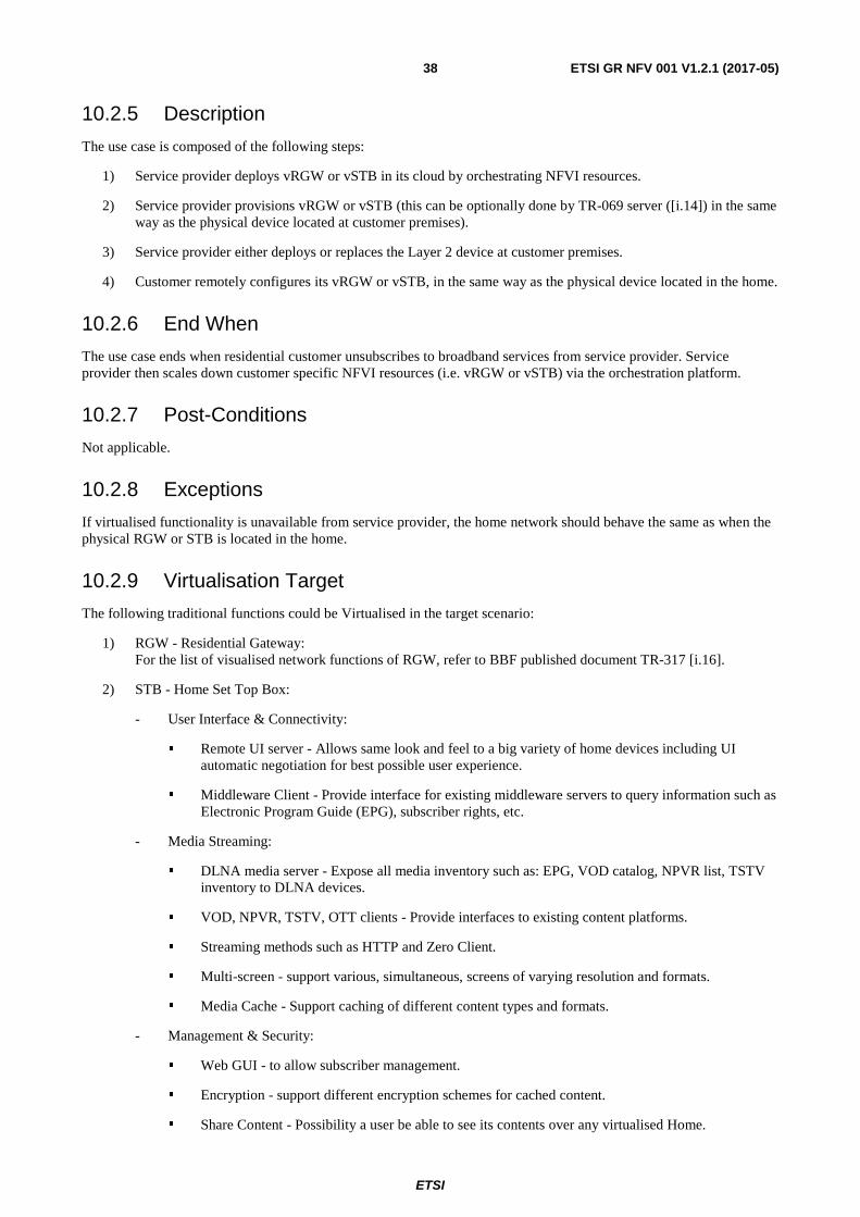
ETSI
ETSI GR NFV 001 V1.2.1 (2017-05)38
10.2.5 Description
The use case is composed of the following steps:
1) Service provider deploys vRGW or vSTB in its cloud by orchestrating NFVI resources.
2) Service provider provisions vRGW or vSTB (this can be optionally done by TR-069 server ([i.14]) in the same way as the physical device located at customer premises).
3) Service provider either deploys or replaces the Layer 2 device at customer premises.
4) Customer remotely configures its vRGW or vSTB, in the same way as the physical device located in the home.
10.2.6 End When
The use case ends when residential customer unsubscribes to broadband services from service provider. Service provider then scales down customer specific NFVI resources (i.e. vRGW or vSTB) via the orchestration platform.
10.2.7 Post-Conditions
Not applicable.
10.2.8 Exceptions
If virtualised functionality is unavailable from service provider, the home network should behave the same as when the physical RGW or STB is located in the home.
10.2.9 Virtualisation Target
The following traditional functions could be Virtualised in the target scenario:
1) RGW - Residential Gateway: For the list of visualised network functions of RGW, refer to BBF published document TR-317 [i.16].
2) STB - Home Set Top Box:
- User Interface & Connectivity:
� Remote UI server - Allows same look and feel to a big variety of home devices including UI automatic negotiation for best possible user experience.
� Middleware Client - Provide interface for existing middleware servers to query information such as Electronic Program Guide (EPG), subscriber rights, etc.
- Media Streaming:
� DLNA media server - Expose all media inventory such as: EPG, VOD catalog, NPVR list, TSTV inventory to DLNA devices.
� VOD, NPVR, TSTV, OTT clients - Provide interfaces to existing content platforms.
� Streaming methods such as HTTP and Zero Client.
� Multi-screen - support various, simultaneous, screens of varying resolution and formats.
� Media Cache - Support caching of different content types and formats.
- Management & Security:
� Web GUI - to allow subscriber management.
� Encryption - support different encryption schemes for cached content.
� Share Content - Possibility a user be able to see its contents over any virtualised Home.
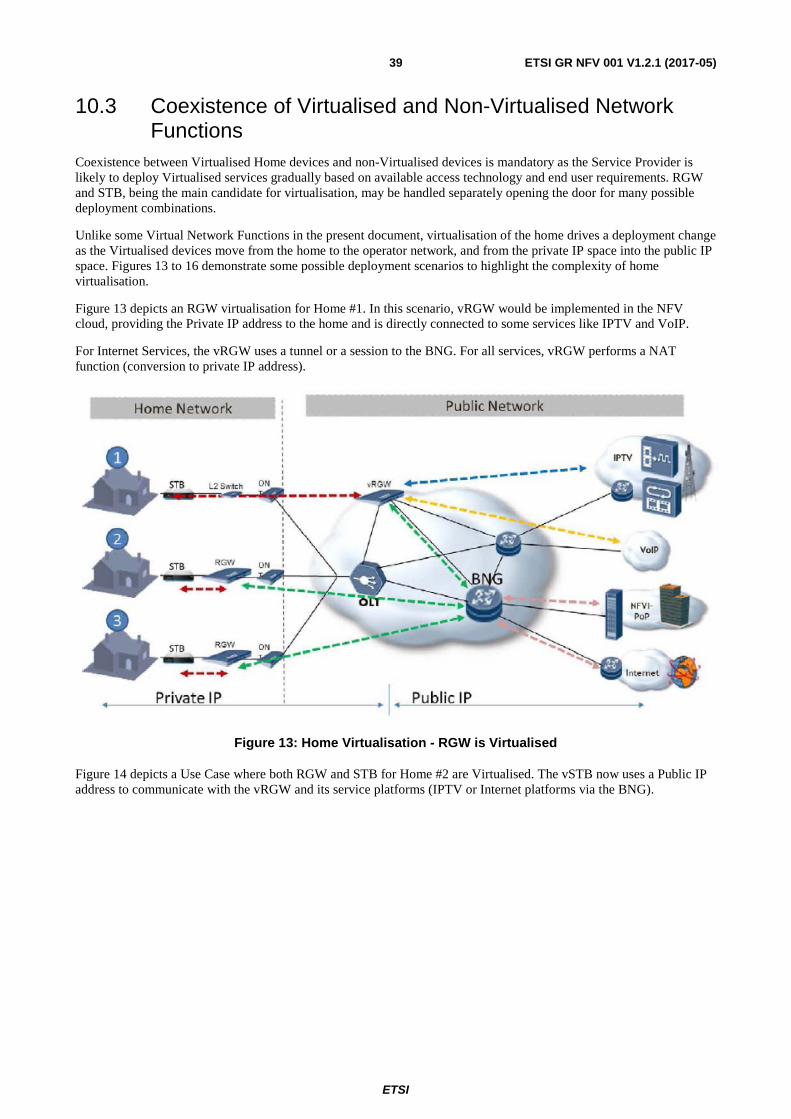
ETSI
ETSI GR NFV 001 V1.2.1 (2017-05)39
10.3 Coexistence of Virtualised and Non-Virtualised Network Functions
Coexistence between Virtualised Home devices and non-Virtualised devices is mandatory as the Service Provider is likely to deploy Virtualised services gradually based on available access technology and end user requirements. RGW and STB, being the main candidate for virtualisation, may be handled separately opening the door for many possible deployment combinations.
Unlike some Virtual Network Functions in the present document, virtualisation of the home drives a deployment change as the Virtualised devices move from the home to the operator network, and from the private IP space into the public IP space. Figures 13 to 16 demonstrate some possible deployment scenarios to highlight the complexity of home virtualisation.
Figure 13 depicts an RGW virtualisation for Home #1. In this scenario, vRGW would be implemented in the NFV cloud, providing the Private IP address to the home and is directly connected to some services like IPTV and VoIP.
For Internet Services, the vRGW uses a tunnel or a session to the BNG. For all services, vRGW performs a NAT function (conversion to private IP address).
Figure 13: Home Virtualisation - RGW is Virtualised
Figure 14 depicts a Use Case where both RGW and STB for Home #2 are Virtualised. The vSTB now uses a Public IP address to communicate with the vRGW and its service platforms (IPTV or Internet platforms via the BNG).
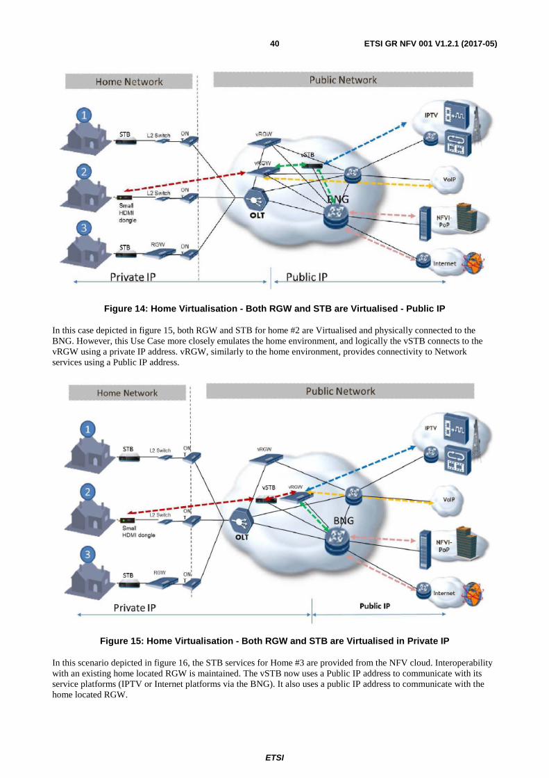
ETSI
ETSI GR NFV 001 V1.2.1 (2017-05)40
Figure 14: Home Virtualisation - Both RGW and STB are Virtualised - Public IP
In this case depicted in figure 15, both RGW and STB for home #2 are Virtualised and physically connected to the BNG. However, this Use Case more closely emulates the home environment, and logically the vSTB connects to the vRGW using a private IP address. vRGW, similarly to the home environment, provides connectivity to Network services using a Public IP address.
Figure 15: Home Virtualisation - Both RGW and STB are Virtualised in Private IP
In this scenario depicted in figure 16, the STB services for Home #3 are provided from the NFV cloud. Interoperability with an existing home located RGW is maintained. The vSTB now uses a Public IP address to communicate with its service platforms (IPTV or Internet platforms via the BNG). It also uses a public IP address to communicate with the home located RGW.
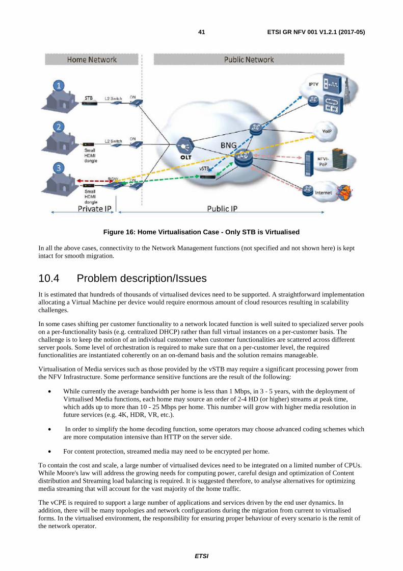
ETSI
ETSI GR NFV 001 V1.2.1 (2017-05)41
Figure 16: Home Virtualisation Case - Only STB is Virtualised
In all the above cases, connectivity to the Network Management functions (not specified and not shown here) is kept intact for smooth migration.
10.4 Problem description/Issues It is estimated that hundreds of thousands of virtualised devices need to be supported. A straightforward implementation allocating a Virtual Machine per device would require enormous amount of cloud resources resulting in scalability challenges.
In some cases shifting per customer functionality to a network located function is well suited to specialized server pools on a per-functionality basis (e.g. centralized DHCP) rather than full virtual instances on a per-customer basis. The challenge is to keep the notion of an individual customer when customer functionalities are scattered across different server pools. Some level of orchestration is required to make sure that on a per-customer level, the required functionalities are instantiated coherently on an on-demand basis and the solution remains manageable.
Virtualisation of Media services such as those provided by the vSTB may require a significant processing power from the NFV Infrastructure. Some performance sensitive functions are the result of the following:
• While currently the average bandwidth per home is less than 1 Mbps, in 3 - 5 years, with the deployment of Virtualised Media functions, each home may source an order of 2-4 HD (or higher) streams at peak time, which adds up to more than 10 - 25 Mbps per home. This number will grow with higher media resolution in future services (e.g. 4K, HDR, VR, etc.).
• In order to simplify the home decoding function, some operators may choose advanced coding schemes which are more computation intensive than HTTP on the server side.
• For content protection, streamed media may need to be encrypted per home.
To contain the cost and scale, a large number of virtualised devices need to be integrated on a limited number of CPUs. While Moore's law will address the growing needs for computing power, careful design and optimization of Content distribution and Streaming load balancing is required. It is suggested therefore, to analyse alternatives for optimizing media streaming that will account for the vast majority of the home traffic.
The vCPE is required to support a large number of applications and services driven by the end user dynamics. In addition, there will be many topologies and network configurations during the migration from current to virtualised forms. In the virtualised environment, the responsibility for ensuring proper behaviour of every scenario is the remit of the network operator.
ETSI
ETSI GR NFV 001 V1.2.1 (2017-05)42
Users and user-applications expect to manage and configure CPE devices even when they are virtualised and provided as a service. This new capability required from the operator is unique to the vCPE. An additional challenge is to guarantee service continuity at the home during network or access link failure (i.e. to match current network behaviour).
Integration of existing management and OSS technologies should be considered.
Optimal functional disaggregation depending on the required functionality performance level has to be assessed (e.g. control plane and data plane functionalities, self-care and operator management access, etc.).
The virtualised environment needs to guarantee complete isolation among users. Data Encryption of cached content and link security is likely to be mandatory.
11 Use Case #6: Virtual Content Delivery Network (vCDN) - Fulfilment
11.1 Motivation Delivery of content, especially of video, is one of the major challenges for all operator networks due to massive growth of high bandwidth traffic delivered to end customers of the network. The growth of video traffic is driven by the shift from broadcast to unicast delivery via IP, by the variety of devices used for video consumption by increasing quality of video delivered via IP networks in terms of resolution and frame rate and by new video applications such as VR/AR and peer-peer video conferencing.
Requirements on quality are also evolving: Internet actors are positioning to provide both Live and On-demand Content Services to internet end-users, with similar quality constraints as for traditional (e.g. broadcast) TV Services.
Moreover, more and more Cloud offers will dramatically increase the amount of content needing to be cached or stored, with the constraint of delivering them as if they were stored locally (i.e. with low latency and consistently high quality).
Integrating Content Delivery Networks (CDNs) into operator networks can be an effective and cost-efficient way to address to the challenges of Video Traffic Delivery. Delivering content streams from compute/storage nodes nearer to the end customer reduces aggregation network bandwidth and equipment, and facilitates delivery of streams with higher bandwidth and consistent quality.
Operators are using CDNs integrated into their own networks to deliver their own managed video services (e.g. VoD complimentary to IPTV, file download), but also to offer wholesale CDN services and to address Over the Top (OTT) video traffic (e.g. via transparent caching).
Specific examples are 3rd party CDN providers or large content providers who ask operators to deploy their proprietary cache nodes inside the ISP network. This comes with benefits for both sides but also with the challenge that eventually the operators will host a zoo of different proprietary cache devices in their premises.
In many current deployments, CDN cache nodes are dedicated physical appliances or software with specific requirements (including dedicated hardware). Often physical appliances and servers for different purposes are deployed side-by-side. Virtualisation can significantly reduce the equipment needed to support multiple providers with local caching.
The current, non-Virtualised, approach comes with a number of disadvantages which are addressed by vCDN:
• The capacity of the devices needs to be designed for peak hours (typically on weekend evenings). During weekdays and business hours, the dedicated hardware appliances and CDN servers are mainly unused but still consuming energy and generating heat.
• It is not practical to react to unforeseen capacity needs, e.g. in case of a live-event where hardware resources need to be deployed in advance.
• The average peak utilization and resiliency of CDN nodes for dedicated purposes or from different partners is lower than it could be if the hardware resources are shared between virtual appliances (i.e. VNFs) on the same NFV Infrastructure.
ETSI
ETSI GR NFV 001 V1.2.1 (2017-05)43
• Dedicated physical devices and servers from several parties drive the complexity of the operator network and increase operational expenses and are wasteful of energy.
• Content delivery is a very volatile market driven by new content formats, protocols, device types, content protection requirements, etc. Dedicated proprietary hardware hinders the necessary flexibility to react to these changes.
• Content Delivery may imply Value Added Services, e.g. to address Security concerns or for optimizing Performance. It may be valuable for the Network Operator to rely on Outsourcing of a Partner's solution rather than deploying and operating its own solution.
11.2 Detailed User Story
11.2.1 Summary
This use case entails the establishment of a vCDN Network Service (NS) in response to a customer request for CDN (of which the vCDN NS may only be a part, e.g. the service provider may also need to establish access to the vCDN for the end users).
Some aspects of vCDN Network Service (NS) are different from other types of network services:
• An instance of vCDN NS is potentially distributed over several data centres (or virtual Data Centres). This leads to several implications:
- The vCDN NS instantiation requests will need to include the location of each Service Access Point (SAP) versus the case where just one location is specified for the entire NS.
- To instantiate a given vCDN NS instance, the vCDN provider may need to orchestrate functional blocks (such as VNFMs, SDN Controllers and even other NS orchestrators such as NFVOs) spanning several data centres.
- The vCDN NS instantiate request may take some time to fulfil. So, it may be more appropriate to use an order between the vCDN consumer and provider. The order can be tracked over time (as its state changes) and also have information such as the expected delivery date for the given request.
- The SAPs for an instance of vCDN NS may change over time (i.e. SAP removals, additions and modifications).
11.2.2 Actor(s)
Actors external to this use case but needed to set the context:
• Customer - the entity that requests the CDN. The CDN request is sent to the service provider, e.g. a Customer Relationship Management (CRM) Business Support System (BSS). The request is decomposed and eventually, an Operations Support System (OSS) functional block (as described in the NFV reference architecture) makes a request to the NFVO for an instance of vCDN.
• Service Provider - the entity that offers CDN service.
• End User - a user of CDN.
Actors specific to this use case:
• vCDN Consumer - this is the entity that requests the vCDN NS. In the NFV reference architecture, this would be either an OSS or a higher-tier NFVO. For the sake of brevity in what follows, sometimes "consumer" is used instead of "vCDN consumer."
• vCDN Provider - this is the entity that provides vCDN NS. In the NFV reference architecture, this would be an NFVO. For the sake of brevity in what follows, sometimes "provider" is used instead of "vCDN provider."
ETSI
ETSI GR NFV 001 V1.2.1 (2017-05)44
11.2.3 Pre-Conditions
The following pre-conditions apply:
• There has been a customer request for CDN.
• The service provider has decomposed the CDN request and has identified the required vCDN NS.
• Not necessarily a pre-condition, but out of scope for this use case, arrangements are made for end user access to the CDN. This could happen after the vCDN is instantiated.
• vCDN NS has been on-boarded.
• Any referenced NSs, VNFs and PNFs in the NS instantiation request already exist.
11.2.4 Begins When
The use case begins when a vCDN NS consumer (e.g. an OSS) requests an instance of vCDN NS from the vCDN NS provider (e.g. an NFVO).
11.2.5 Description
The following steps are followed in instantiating the vCDN NS instance:
1) The provider (e.g. an NFVO) decomposes the request and identifies what nested NSs, VNFs (and perhaps PNFs) are needed to support the vCDN NS.
a) The request from the consumer may reference existing NSs, VNFs and PNFs that are to be used in the vCDN NS. The referenced NSs will be components of the new NS that is being instantiated. The provider will make use of the referenced NSs, VNFs and PNFs, if possible.
b) The provider will orchestrate the instantiation of any additional NSs and VNFs that are needed (beyond the existing VNFs and PNFs referenced in the consumer's request). This would typically entail the vCDN provider making requests to subtending function blocks such as other NS providers or Network Function (NF) providers such as VNFMs or SDN Controllers.
c) Example VNFs in support of the vCDN NS: virtual Content Server (these could be of various types with some types for content that is accessed frequently and other types for content that is not accessed to often), virtual Security Server (used to authenticate end users) and CDN Controller (has the ability to select an appropriate virtual Content Service to answer the end-user's request).
2) The provider responds back to the consumer with an indication that the vCDN NS has been instantiated.
a) Subsequently, the consumer may request (from the provider) a list of the NSs, VNFs and PNFs that are being used in support of the vCDN NS instance.
3) Alternately, given that the vCDN NS instance may take some time to create (e.g. because it is geographically distributed and several functional blocks may be involved in its instantiation), an order mechanism may be used. In this case, the provider would initially respond to the consumer with an indication that an order has been created (with an expected delivery date/time) and provide a handle to the order object (so that the consumer can check on the progress of the order).
4) If the vCDN provider does not handle the application specific aspects of the VNFs or PNFs, the NS might not yet be fully configured. In this case, the vCDN consumer needs to send additional configuration requests to another functional block that can handle application-specific configuration for the supporting VNFs and PNFs.
a) The functional blocks (handling the application-specific configuration of the vCDN NS and subtending components) will respond back to the vCDN consumer.
The consumer may subsequently modify the vCDN NS by, for example, requesting the addition of Service Access Points (SAPs), removal of SAPs or modification of the characteristics of some or all of the SAPs (e.g. increasing the number of end users that can be support simultaneously).
ETSI
ETSI GR NFV 001 V1.2.1 (2017-05)45
11.2.6 End When
The use case ends when the consumer receives the last response concerning configuration of the application-specific aspects of the VNFs and PNFs in support of the NS.
11.2.7 Post-Conditions
In the case of success, the vCDN NS is instantiated as requested.
In case of partial success (possible if the request is best effort), the vCDN NS is only partially instantiated as requested, e.g. perhaps some of the SAPs could not be created.
In case of failure:
• Atomic (all or nothing request) - nothing is established with regard to the vCDN NS.
• Best effort (if the minimum requirements are not met for the vCDN NS, perhaps as defined by the consumer or perhaps as define globally in the descriptor for vCDN NS) - nothing is established with regard to the vCDN NS.
In either case, roll-back (clean-up) is expected.
11.2.8 Exceptions
The following exceptions have been identified:
• Insufficient resources are present to support the requested vCDN NS. The vCDN NS instantiation request violates pre-defined conditions (either in the descriptor for vCDN NS or perhaps in a policy associated with the vCDN NS type).
11.2.9 Virtualisation Target
CDN is a generic description of a design which combines multiple components, such as cache nodes and CDN controllers.
Basically, the CDN controller objective is to select a cache node (or a pool of cache nodes) in response to the end-user request, and then redirect the end-user to the selected cache node (a type of virtual Content Server VNF). The Cache Node will answer to the end-user request and deliver the requested content to the end user. The CDN controller is a centralized component, and CDN cache nodes are distributed within the Network and in Network-PoPs.
Virtualisation of CDN potentially covers all components of the CDN, though the first impact would probably be on cache nodes for achieving acceptable performances (e.g. throughput, latency).
Deploying CDN nodes as virtual appliances (i.e. VNFs) on a standardized environment will overcome most of the challenges mentioned above:
1) Resources can be allocated to other types of VNFs during weekdays and business hours.
2) Overall capacity can be shared amongst several VNFs.
3) Operational processes for allocating resources for different parties are harmonized.
4) As VNFs are just software, it is easy to replace or add them in case of new requirements in content delivery.
Running CDN nodes as VNFs on an operator owned infrastructure will enable new kinds of wholesale business models towards CDN providers and large content providers with private CDNs if there is a standardized way to deploy and operate such 3rd party CDN nodes in a controlled way in the operator environment (i.e. beyond the co-location environments).
ETSI
ETSI GR NFV 001 V1.2.1 (2017-05)46
11.3 Coexistence of Virtualised and Non-Virtualised Network Functions
With a CDN designed as loosely coupled software components, a variety of scenarios of coexisting virtualised and non-virtualised components are possible.
Given that the CDN controller is able to control cache nodes deployed on virtualised and non-virtualised server instances in parallel the following scenarios are possible:
• Centralized cache nodes can run on virtualised (i.e. Cloud) resources while cache nodes distributed deeper into the network might run on physical appliances for operational reasons.
• Centralized cache clusters might run on dedicated non-virtualised servers for performance reasons while cache node instances distributed within in the network may be running on virtualised resources available in other network devices.
Within a migration scenario from non-virtualised to virtualised, the legacy cache nodes can be kept in production until the end of their hardware life-cycle is reached (i.e. operational efficiency is still adequate) while new capacity is added to the CDN by deploying the same software functionality on virtualised resources.
11.4 Problem description/Issues The following problems and issues have been identified:
1) Possible need for an ordering API between the vCDN consumer and provider.
2) The need to identify SAP locations for an instance of vCDN (compared to other NSs where it may be sufficient to just specify one location for the entire NS).
3) Cost-efficiency (cache software is often relative simple software, deployed on low-cost servers).
4) Performance ratio in comparison to bare metal (loss need to be outweighed by operational benefits).
5) Deterministic performance (dimensioning would remain stable whatever the use of Virtualised HW resources).
6) Allowing the right balance of network I/O to CPU power to storage I/O performance (e.g. RAM and HDD).
7) Flexibility to fulfil specific storage density requirements, e.g. to cache a large catalog of popular content.
8) Compliance of cache nodes with main monitoring and reporting requirements (e.g. SNMP, syslog, etc.) so that the operator is able to manage different types of cache nodes for a CDN NS.
Ability to select specific cached content (e.g. video/HTTP) and replicate/duplicate these selected content items during delivery via virtual switching to a Quality of Experience (QoE) assessment Virtualised function without degrading the overall performance of the Virtualised CDN function.
12 Use Case #7: Fixed Access Network Functions Virtualisation
12.1 Motivation The main costs and bottlenecks in a network often occur in the access. For the wireline fixed access network, the most prevalent fixed broadband access technologies today are based on Digital Subscriber Line (DSL) and Hybrid Fiber Coax (HFC), with Fiber to the Premises (FTTP) in new build areas.
ETSI
ETSI GR NFV 001 V1.2.1 (2017-05)47
High bandwidth fixed access systems typically require electronic systems to be deployed in remote nodes located in the street or in multiple-occupancy buildings. These systems need to be compact and energy efficient to minimize accommodation and thermal problems and to allow novel powering schemes. These new low power remote nodes and the corresponding customer modems, need to be as simple as possible with particular regards to fault management and have a long service life. To achieve these goals and permit economic large scale deployment the following features are foreseen as requirements:
1) Low cost.
2) Minimal power consumption at remote node.
3) Complex processing moved to the head-end to simplify the remote equipment.
4) Low-power stand-by and partial operational modes.
5) Minimized truck-rolls to both the remote node and customer premises.
6) Automated provisioning.
Access network virtualisation directly addresses item 3 in this list, and through the simplification of the remote node, should also help with items 1 and 2.
The Optical Line Terminal (OLT) terminates aggregated traffic(FTTP and other types of access technology), and performs tasks that can be virtualised as a "Virtual OLT" (vOLT). The vOLT can include virtualised functions such as: VLAN tagging, layer 2/3 forwarding or SDN control, discovery/initialization, QoS enforcement, and traffic management.
Current access network equipment is normally owned and operated by a single organizational entity. Virtualisation has the additional benefit that it can (in theory) support so-called multiple tenancy, whereby more than one organizational entity can either be allocated, or given direct control of, a dedicated partition of a virtual access node.
Finally, virtualising broadband access nodes can enable synergies to be exploited by the co-location of wireless access nodes in a common NFV platform framework (i.e. common NFVI-PoPs), thereby improving the deployment economics and reducing the overall energy consumption of the combined solution.
12.2 Detailed User Story
12.2.1 Summary
Access Network Functions Virtualisation will be initially applied to access nodes and aggregation nodes typically located at the edge of the access network, and within multiple-occupancy buildings. These nodes in order to be economically viable are normally compact, with very low power consumption and very low maintenance costs. By applying NFV principles, hardware complexity at the remote node can be reduced both saving energy and providing an enhanced degree of future proofing through centralized software updates as services evolve. The nodes, if properly dimensioned, can be used to host service related virtual network functions as described in other sections of this document, for example SDN, to take advantage of low latency and bandwidth aggregation efficiencies.
12.2.2 Actor(s)
Actors external to this use case:
• The subscribers to the access network service.
Actors specific to this use case:
• Network Provider. Sometimes also called the Infrastructure Provider (InP) or wholesaler. Owns and operates the physical access network.
• Virtual Network Operator (VNO). Sometimes also called the Service Provider (SP), Communications Provider (CP), or retailer. The VNO uses a virtualised network that is a logical part of the physical network which is operated by the Network Provider.
• Note that in many cases these actors are subsumed into a single entity.
ETSI
ETSI GR NFV 001 V1.2.1 (2017-05)48
12.2.3 Pre-Conditions
To achieve the Access Network Functions Virtualisation vision, several challenges need to be solved: increasing the level of flexibility, transparency and optimization for delivering the service.
These challenges can be addressed by considering some major improvements to the network architecture:
• Move computationally intensive functions to a more central point.
- The resources in the network need to be more effectively utilized. This means more customers will share the computational resource thus increasing the overall utilization. It will also simplify the design of the end nodes. Similarly, functionality contained in customer premises equipment can also be moved to a more central point but this is covered in a separate use case document on virtualisation of the home environment.
• Synergies can be exploited by deploying wireless access nodes at the same physical point in the network as the fixed access nodes.
- These nodes can share the fibre backhaul and power connection, and the associated centralized computational resources can also be shared thereby lowering the cost and energy consumption of the overall solution.
While virtualisation can be applied to any broadband access network, it is particularly useful for fiber-deep architectures such as Fibre-to-the-Node (FTTN), Fibre-To-The-distribution point (FTTdp) plus cable architectures. These architectures have small remotely-powered access nodes which can benefit greatly with assistance from virtualised functions located at a central node. The remote access nodes facilitate shorter innovation cycles if virtualised functions are implemented in a central location controlling simpler and cheaper hardware located at the remote nodes. Examples of such virtualised functions are listed in clause 14.2.5.
Another goal is producing 'green' virtualisation platforms with network hardware optimized for 'green' operation. Energy usage can be reduced by using smart virtual functions to maximize 'green' characteristics, at the:
• Link level, where the energy can be reduced by optimizing the complex trade-offs involved with dynamic adaptation of different operational parameters, service levels, traffic, delay, and sleep modes.
• Network level, where the energy can be reduced by selectively forcing nodes and/or links to go to sleep in particular situations and by using resource consolidation, cooperative relaying and 'green' routing.
To achieve the goals of efficiency, interoperability and manageability of the Access Network which may have a heterogeneous set of resources, an Abstraction Layer and a common northbound interface are required to hide the complexity and specifics of each technology. Access Network Functions Virtualisation will take a step further by providing a richer interface which can be shared by different access technologies. However some issues could still remain technology-dependent where there is a tight relationship with the underlying technology. This means that a low level interface linked to the technology could still be required.
In summary, Access Network Functions Virtualisation will generate a single platform for different applications, users and tenants, where service providers share a "pool" of managed connectivity resources which can be dynamically allocated and combined to deploy on-demand services across different customer bases. Broadband resources will be more efficiently utilized and new business models will emerge.
12.2.4 Begins When
This use case begins when the access network is re-engineered to virtualise fixed access network functions. This may occur either in a green field deployment, or as an upgrade to an existing brownfield deployment.
12.2.5 Description
Various scenarios of access networks and virtualisation possibilities for functionality and control planes are shown in figure 17. Marked in Yellow are network elements whose management & control plane functionality may be separated and run in a NFV enabled CO. Target platforms for virtualisation are any NFV components in a Network Provider domain, virtual network operator domain, or third-party hosted domain.
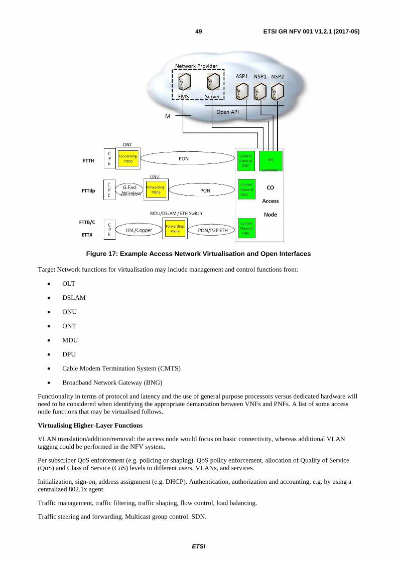
ETSI
ETSI GR NFV 001 V1.2.1 (2017-05)49
Figure 17: Example Access Network Virtualisation and Open Interfaces
Target Network functions for virtualisation may include management and control functions from:
• OLT
• DSLAM
• ONU
• ONT
• MDU
• DPU
• Cable Modem Termination System (CMTS)
• Broadband Network Gateway (BNG)
Functionality in terms of protocol and latency and the use of general purpose processors versus dedicated hardware will need to be considered when identifying the appropriate demarcation between VNFs and PNFs. A list of some access node functions that may be virtualised follows.
Virtualising Higher-Layer Functions
VLAN translation/addition/removal: the access node would focus on basic connectivity, whereas additional VLAN tagging could be performed in the NFV system.
Per subscriber QoS enforcement (e.g. policing or shaping). QoS policy enforcement, allocation of Quality of Service (QoS) and Class of Service (CoS) levels to different users, VLANs, and services.
Initialization, sign-on, address assignment (e.g. DHCP). Authentication, authorization and accounting, e.g. by using a centralized 802.1x agent.
Traffic management, traffic filtering, traffic shaping, flow control, load balancing.
Traffic steering and forwarding. Multicast group control. SDN.
ETSI
ETSI GR NFV 001 V1.2.1 (2017-05)50
Network slicing with data sharing for multi-operator network control and management. Here an abstraction layer connects the physical network to multiple virtual access node VNFs, each of which allows control and data dissemination to each Virtual Network Operator (VNO) for particular functions.
Control and configuration. Each VNO controls and configures their own virtual access node dataset of configuration objects.
Diagnostics and state information. Each VNO accesses virtual functions providing test, diagnostic, performance, and status information.
Candidate Layer 1-2 Virtual Network Functions
Control of Dynamic Rate Allocation (DRA). DRA schedules traffic, such as G.fast Dynamic Time Assignment (DTA), or PON Dynamic Bandwidth Allocation (DBA). Real-time DRA is likely to stay on the equipment, but the configuration of DRA (e.g. setting traffic triggers) can involve complex non-real time trade-offs in policy and subscriber management, and so DRA configuration can be virtualised.
Dynamic resource assignment; e.g. fibre access and backhaul bandwidth assignment.
On-line reconfiguration management.
Dynamic Spectrum Management (DSM) for DSLs and G.fast systems.
Diagnostics and transmission optimization.
Power Control Entity (PCE), cross-layer low-power mode control, for G.fast. There are a number of thresholds and other settings for low-power modes of individual transceivers, these settings and primitives can be determined by a virtualised power control entity.
Vectoring control and management for G.fast. Vectoring, low-power mode control, and TDD scheduling vary in a complex set of dependencies to affect performance, throughput, and power usage. A virtual access node function can select a good trade-off.
12.2.6 End When
There is no anticipated end to fixed access network functions virtualisation.
12.2.7 Post-Conditions
Not applicable.
12.2.8 Exceptions
The typical user will subscribe to services and expect to be able to use them from any access point with the required QoS/QoE regardless of the technology, and with no need for user reconfiguration. However, a set of technical challenges need to be addressed to realize this objective:
• Existing access technologies need to evolve to support the requirements of new services, e.g. in terms of capacity, stability, or real-time response.
• Coexistence of 'legacy' technologies and services with the new ones.
• Network management needs to evolve to allow rapid provisioning of broadband access, no matter from where, or via which technology, with the required parameters of capacity and QoS defined by a set of services.
• A 'new' feature that can be implemented by network management is to allow elements to 'sleep' in low-power modes. Control of low-power modes involves trade-offs between power, performance, and stability, a VNF can better optimize these trade-offs by tapping into more computing and storage resources than PNFs could.
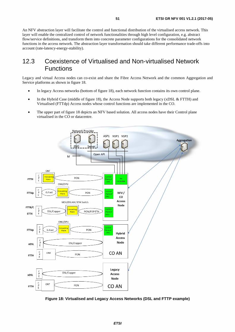
ETSI
ETSI GR NFV 001 V1.2.1 (2017-05)51
An NFV abstraction layer will facilitate the control and functional distribution of the virtualised access network. This layer will enable the centralized control of network functionalities through high level configuration, e.g. abstract flow/service definitions, and transform them into concrete parameter configurations for the consolidated network functions in the access network. The abstraction layer transformation should take different performance trade-offs into account (rate-latency-energy-stability).
12.3 Coexistence of Virtualised and Non-virtualised Network Functions
Legacy and virtual Access nodes can co-exist and share the Fibre Access Network and the common Aggregation and Service platforms as shown in figure 18.
• In legacy Access networks (bottom of figure 18), each network function contains its own control plane.
• In the Hybrid Case (middle of figure 18), the Access Node supports both legacy (xDSL & FTTH) and Virtualised (FTTdp) Access nodes whose control functions are implemented in the CO.
• The upper part of figure 18 depicts an NFV based solution. All access nodes have their Control plane virtualised in the CO or datacentre.
Figure 18: Virtualised and Legacy Access Networks (DSL and FTTP example)
ETSI
ETSI GR NFV 001 V1.2.1 (2017-05)52
12.4 Problem description/Issues General and External Factors:
• Today's fixed access technology standards do not consider virtualisation.
• Increased backhaul bandwidth requirements to implement centralized virtualisation functions may result in reduced energy saving and reduced economic benefits.
The distributed NFV solution should:
• Identify the types of resources that should be made available in the access network. This starts by identifying service classes that can benefit from a distributed cloud, and the definition of evaluation criteria.
• Identify where in the access network functions can be optimally and practically located. This includes the creation of an access topology model, and a performance comparison with state-of-the-art centralized cloud services.
In addition, the management of virtualised functions in access should take into account:
• The impact of the location of access resources on the selection of location for the VNFI.
• The elastic allocation of access resources to services.
• Smooth migration of VNFs between locations in the access network.
• Robust methods for cross-domain applications of VNFs, for instance between an operator and a service provider.
• Resource management algorithms with access-specific constraints.
Broadband connectivity resource management is required to provide an efficient and secure mechanism to share the access and aggregation network between several service providers, offering a management API, which will be used by a Broadband controller. This will require:
• A virtualisation mechanism of the access and aggregation network and corresponding API.
• A bandwidth management API and implementation of a functional subset.
• Investigation of advanced AAA mechanisms.
To quantify the benefits of Access Network Functions Virtualisation to end users, network operators and service providers, it is necessary to investigate the following:
• Identifying the optimum demarcation between non-virtualised Layer 1 functions and virtualised Layer 2 and above functions.
• Quantify benefits of simplification of small low-power remote devices by the development of NFV based Layer 2 processing and QoS management approaches that facilitates migration of functionality between PNFs and VNFs.
• Consideration of key functional requirements such as dynamic QoS models for cases where the service mix enters/exits from low-power modes i.e. bandwidth changes will not necessarily be instantaneous and richer QoS models may be required to cope with the service requirements.
• Rate stability and variability will need to be considered against users' channel access, data flows, data packets, data rates, transceiver activity/corresponding power dissipation with regards to targeting an abstraction of various network-wide performance trade-offs. Consider which functions may be shifted from end-user to access including end-to-end security, access control, QoS for heterogeneous networks and third party services.
ETSI
ETSI GR NFV 001 V1.2.1 (2017-05)53
13 Use Case #8: Crypto as a Service (CaaS)
13.1 Motivation The move to take advantage of the cloud including private, hybrid and public clouds, has been faced with challenges and has put extra requirements on infrastructure that enables and secures applications, including virtual Firewalls, ADCs, and Routers (with or without IPsec). This coupled with the need to have computing and storage infrastructure resources shared among multi-tenants, makes the move even more challenging.
The Crypto as a Service (CaaS) use case is an example of a (serving) VNF providing services to other (client) VNFs as it applies to network functions and applications dealing with encrypted traffic.
13.2 Detailed User Story
13.2.1 Summary
Critical network functions such as FW, IPS and LB are being virtualised through NFV principles. As these vFW, vIPS, vLB move to the cloud, they are faced with performance, key management, and scaling issues. The crypto as a service (CaaS) use case addresses the need for high-performance cryptographic key operation offload and centralized key management for use by these virtual network functions (VNFs) dealing with encrypted traffic. CaaS also addresses the needs of applications needing PKI (Public Key Infrastructure) functions in the cloud computing infrastructure, including but not limited to multi-tenant public cloud. An example is tenants requiring VM to VM, east-west traffic with IPSec encryption, or a banking application requiring PKI.
13.2.2 Actor(s)
Customer: The entity (e.g. an enterprise) that has signed up to use network services from the Cloud Service Provider (CSP) in the form of firewall, load balancing, intrusion prevention and traffic monitoring, or other applications which can use centralized crypto and key management as a service.
Service Provider: The entity that offers these network services, including private and public cloud service providers. This service is usually offered to a customer over a remote WAN connection.
An additional actor to make this possible is the availability of an open source CaaS client software for ease of integration with the client VNFs or end applications. This enables the client VNFs to take advantage of the vCaaS.
13.2.3 Pre-Conditions
Deployment of the virtualised FW, LB, IPS or TM in the cloud service provider: NFV infrastructure (CSP: NFVI), or other applications needing crypto processing and key management. These VNFs are referred to as the client VNFs, as they use the vCaaS service.
13.2.4 Begins When
Activation of the serving CaaS function is triggered by the launch of the client VNFs or applications listed above, with the integrated CaaS client software. A CaaS partition will launch with required key storage and crypto (symmetric or asymmetric) performance based on client VNFs requirements. It will deactivate as the client VNFs are no longer in use.
13.2.5 Description
SSL Encryption
Only few years ago, large financial institutions, ecommerce and government agencies were the primary organizations employing the cryptographic protocol historically known as the Secure Sockets Layer (SSL) also known as Transport Layer Security (TLS). Today, SSL is almost everywhere. Enterprises and cloud providers are scrambling to encrypt the majority of traffic, including everything from email and social media to streaming video.
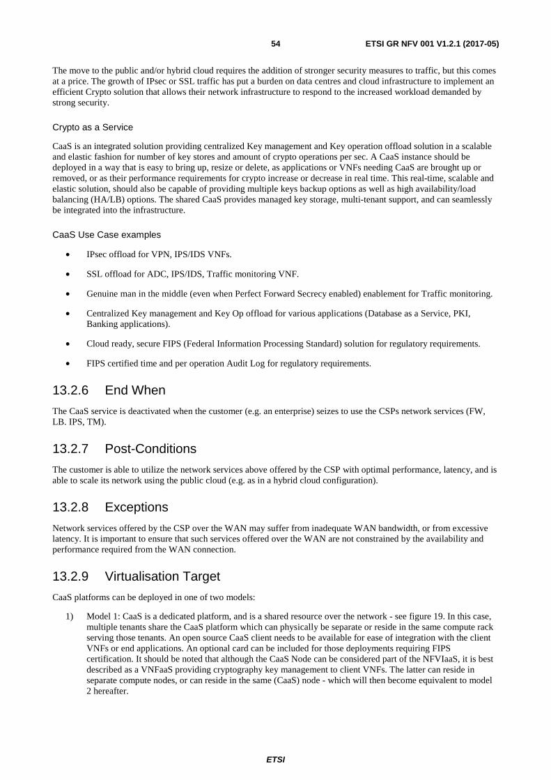
ETSI
ETSI GR NFV 001 V1.2.1 (2017-05)54
The move to the public and/or hybrid cloud requires the addition of stronger security measures to traffic, but this comes at a price. The growth of IPsec or SSL traffic has put a burden on data centres and cloud infrastructure to implement an efficient Crypto solution that allows their network infrastructure to respond to the increased workload demanded by strong security.
Crypto as a Service
CaaS is an integrated solution providing centralized Key management and Key operation offload solution in a scalable and elastic fashion for number of key stores and amount of crypto operations per sec. A CaaS instance should be deployed in a way that is easy to bring up, resize or delete, as applications or VNFs needing CaaS are brought up or removed, or as their performance requirements for crypto increase or decrease in real time. This real-time, scalable and elastic solution, should also be capable of providing multiple keys backup options as well as high availability/load balancing (HA/LB) options. The shared CaaS provides managed key storage, multi-tenant support, and can seamlessly be integrated into the infrastructure.
CaaS Use Case examples
• IPsec offload for VPN, IPS/IDS VNFs.
• SSL offload for ADC, IPS/IDS, Traffic monitoring VNF.
• Genuine man in the middle (even when Perfect Forward Secrecy enabled) enablement for Traffic monitoring.
• Centralized Key management and Key Op offload for various applications (Database as a Service, PKI, Banking applications).
• Cloud ready, secure FIPS (Federal Information Processing Standard) solution for regulatory requirements.
• FIPS certified time and per operation Audit Log for regulatory requirements.
13.2.6 End When
The CaaS service is deactivated when the customer (e.g. an enterprise) seizes to use the CSPs network services (FW, LB. IPS, TM).
13.2.7 Post-Conditions
The customer is able to utilize the network services above offered by the CSP with optimal performance, latency, and is able to scale its network using the public cloud (e.g. as in a hybrid cloud configuration).
13.2.8 Exceptions
Network services offered by the CSP over the WAN may suffer from inadequate WAN bandwidth, or from excessive latency. It is important to ensure that such services offered over the WAN are not constrained by the availability and performance required from the WAN connection.
13.2.9 Virtualisation Target
CaaS platforms can be deployed in one of two models:
1) Model 1: CaaS is a dedicated platform, and is a shared resource over the network - see figure 19. In this case, multiple tenants share the CaaS platform which can physically be separate or reside in the same compute rack serving those tenants. An open source CaaS client needs to be available for ease of integration with the client VNFs or end applications. An optional card can be included for those deployments requiring FIPS certification. It should be noted that although the CaaS Node can be considered part of the NFVIaaS, it is best described as a VNFaaS providing cryptography key management to client VNFs. The latter can reside in separate compute nodes, or can reside in the same (CaaS) node - which will then become equivalent to model 2 hereafter.
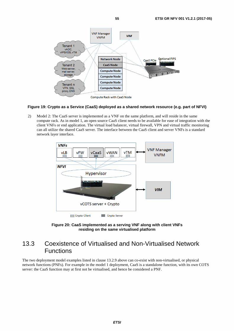
ETSI
ETSI GR NFV 001 V1.2.1 (2017-05)55
Figure 19: Crypto as a Service (CaaS) deployed as a shared network resource (e.g. part of NFVI)
2) Model 2: The CaaS server is implemented as a VNF on the same platform, and will reside in the same compute rack. As in model 1, an open source CaaS client needs to be available for ease of integration with the client VNFs or end application. The virtual load balancer, virtual firewall, VPN and virtual traffic monitoring can all utilize the shared CaaS server. The interface between the CaaS client and server VNFs is a standard network layer interface.
Figure 20: CaaS implemented as a serving VNF along with client VNFs residing on the same virtualised platform
13.3 Coexistence of Virtualised and Non-Virtualised Network Functions
The two deployment model examples listed in clause 13.2.9 above can co-exist with non-virtualised, or physical network functions (PNFs). For example in the model 1 deployment, CaaS is a standalone function, with its own COTS server: the CaaS function may at first not be virtualised, and hence be considered a PNF.
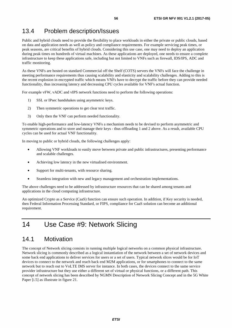
ETSI
ETSI GR NFV 001 V1.2.1 (2017-05)56
13.4 Problem description/Issues Public and hybrid clouds need to provide the flexibility to place workloads in either the private or public clouds, based on data and application needs as well as policy and compliance requirements. For example servicing peak times, or peak seasons, are critical benefits of hybrid clouds. Considering this use case, one may need to deploy an application during peak times on hundreds of virtual machines. As these applications are deployed, one needs to ensure a complete infrastructure to keep these applications safe, including but not limited to VNFs such as firewall, IDS/IPS, ADC and traffic monitoring.
As these VNFs are hosted on standard Commercial off the Shelf (COTS) servers the VNFs will face the challenge in meeting performance requirements thus causing scalability and elasticity and scalability challenges. Adding to this is the recent explosion in encrypted traffic which means VNFs have to decrypt the traffic before they can provide needed functionality, thus increasing latency and decreasing CPU cycles available for VNF's actual function.
For example vFW, vADC and vIPS network functions need to perform the following operations:
1) SSL or IPsec handshakes using asymmetric keys.
2) Then symmetric operations to get clear text traffic.
3) Only then the VNF can perform needed functionality.
To enable high-performance and low-latency VNFs a mechanism needs to be devised to perform asymmetric and symmetric operations and to store and manage their keys - thus offloading 1 and 2 above. As a result, available CPU cycles can be used for actual VNF functionality.
In moving to public or hybrid clouds, the following challenges apply:
• Allowing VNF workloads to easily move between private and public infrastructures, presenting performance and scalable challenges.
• Achieving low latency in the new virtualised environment.
• Support for multi-tenants, with resource sharing.
• Seamless integration with new and legacy management and orchestration implementations.
The above challenges need to be addressed by infrastructure resources that can be shared among tenants and applications in the cloud computing infrastructure.
An optimized Crypto as a Service (CaaS) function can ensure such operation. In addition, if Key security is needed, then Federal Information Processing Standard, or FIPS, compliance for CaaS solution can become an additional requirement.
14 Use Case #9: Network Slicing
14.1 Motivation The concept of Network slicing consists in running multiple logical networks on a common physical infrastructure. Network slicing is commonly described as a logical instantiation of the network between a set of network devices and some back end applications to deliver services for users or a set of users. Typical network slices would be for IoT devices to connect to the network and reach back end M2M applications, or for smartphones to connect to the same network but to reach out to VoLTE IMS server for instance. In both cases, the devices connect to the same service provider infrastructure but they use either a different set of virtual or physical functions, or a different path. This concept of network slicing has been described by NGMN Description of Network Slicing Concept and in the 5G White Paper [i.5] as illustrate in figure 21.
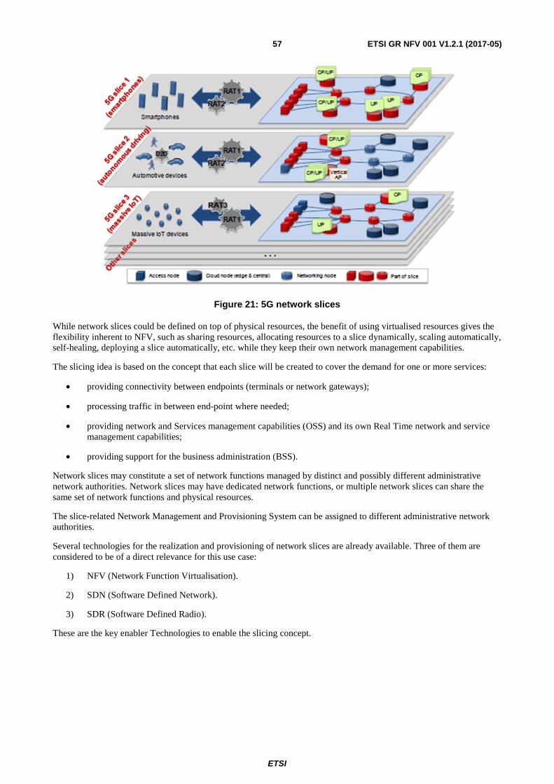
ETSI
ETSI GR NFV 001 V1.2.1 (2017-05)57
Figure 21: 5G network slices
While network slices could be defined on top of physical resources, the benefit of using virtualised resources gives the flexibility inherent to NFV, such as sharing resources, allocating resources to a slice dynamically, scaling automatically, self-healing, deploying a slice automatically, etc. while they keep their own network management capabilities.
The slicing idea is based on the concept that each slice will be created to cover the demand for one or more services:
• providing connectivity between endpoints (terminals or network gateways);
• processing traffic in between end-point where needed;
• providing network and Services management capabilities (OSS) and its own Real Time network and service management capabilities;
• providing support for the business administration (BSS).
Network slices may constitute a set of network functions managed by distinct and possibly different administrative network authorities. Network slices may have dedicated network functions, or multiple network slices can share the same set of network functions and physical resources.
The slice-related Network Management and Provisioning System can be assigned to different administrative network authorities.
Several technologies for the realization and provisioning of network slices are already available. Three of them are considered to be of a direct relevance for this use case:
1) NFV (Network Function Virtualisation).
2) SDN (Software Defined Network).
3) SDR (Software Defined Radio).
These are the key enabler Technologies to enable the slicing concept.
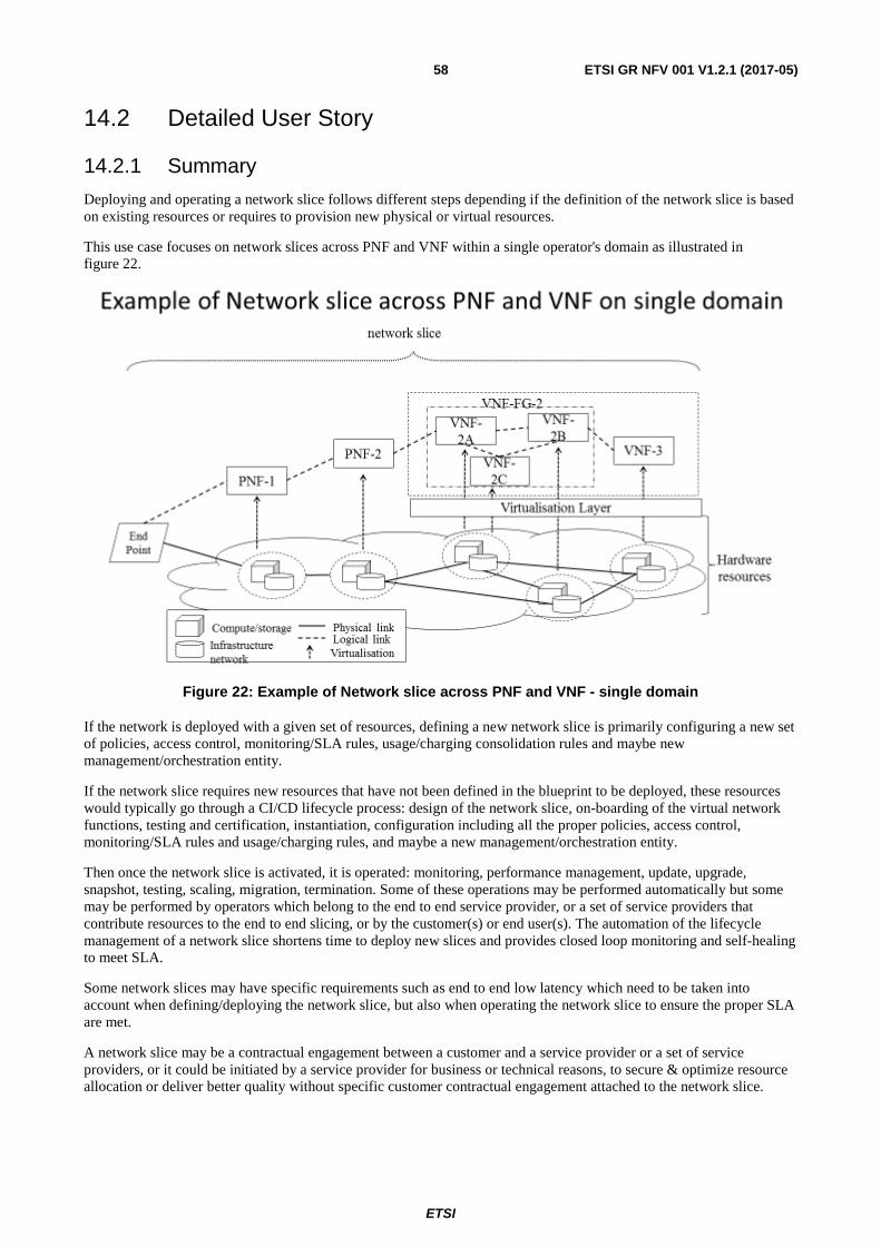
ETSI
ETSI GR NFV 001 V1.2.1 (2017-05)58
14.2 Detailed User Story
14.2.1 Summary
Deploying and operating a network slice follows different steps depending if the definition of the network slice is based on existing resources or requires to provision new physical or virtual resources.
This use case focuses on network slices across PNF and VNF within a single operator's domain as illustrated in figure 22.
Figure 22: Example of Network slice across PNF and VNF - single domain
If the network is deployed with a given set of resources, defining a new network slice is primarily configuring a new set of policies, access control, monitoring/SLA rules, usage/charging consolidation rules and maybe new management/orchestration entity.
If the network slice requires new resources that have not been defined in the blueprint to be deployed, these resources would typically go through a CI/CD lifecycle process: design of the network slice, on-boarding of the virtual network functions, testing and certification, instantiation, configuration including all the proper policies, access control, monitoring/SLA rules and usage/charging rules, and maybe a new management/orchestration entity.
Then once the network slice is activated, it is operated: monitoring, performance management, update, upgrade, snapshot, testing, scaling, migration, termination. Some of these operations may be performed automatically but some may be performed by operators which belong to the end to end service provider, or a set of service providers that contribute resources to the end to end slicing, or by the customer(s) or end user(s). The automation of the lifecycle management of a network slice shortens time to deploy new slices and provides closed loop monitoring and self-healing to meet SLA.
Some network slices may have specific requirements such as end to end low latency which need to be taken into account when defining/deploying the network slice, but also when operating the network slice to ensure the proper SLA are met.
A network slice may be a contractual engagement between a customer and a service provider or a set of service providers, or it could be initiated by a service provider for business or technical reasons, to secure & optimize resource allocation or deliver better quality without specific customer contractual engagement attached to the network slice.
ETSI
ETSI GR NFV 001 V1.2.1 (2017-05)59
Multiple network slices on the same administrative domain may be orchestrated jointly by an administrative domain management and orchestration instance that will manage the lifecycle of network slices and the optimized allocation of resources and connectivity for these slices while several network slices across multiple domains may require some coordination across multiple domain management and orchestration instances. Several network slices could be orchestrated jointly.
Each network slice has its own network slice manager, in relation with an operator overarching management and orchestration. Whether a network slice has its own manager or can be managed by another manager is left for further study.
In some cases, Network & Service Management & Orchestration functionalities will be part of the network functions in order to meet the business requirements such as low latency , automation functions (self-healing, SON, etc.)
A typical example is setting a network slice between a given application in a connected car and a back end application (i.e. WebRTC or Video streamer). The end user wants to stream videos he has purchased before his trip. The videos are stored on video streamer in the network, ready to be streamed to the car with proper quality. The car is connected to a cellular network and is driving. It is running an application that is requesting a given frequency band, i.e. LTE, a given bandwidth, end to end quality of service, etc.
14.2.2 Actor(s)
Actors external to this use case (business needs) but needed to set the context:
• Customer - the entity that requests the end to end service that drives the need for a network slice. The request is sent to the service provider, e.g. a CRM BSS.
• Service Provider - the entity that delivers the end to end service to the Customer.
• network slice Provider - the entity that offers the network slice.
• Sub-network Service Provider - the entity that offers a sub-network that contributes to the network slice.
- As an example, a network slice Provider may offer network slices to an automotive service but rely on a set of underlying sub-network Service Provider': one that provide the access network part of the slice, another that provides the core network part.
• End User - the entity that uses the service delivered by the network slice.
14.2.3 Pre-Conditions
The following pre-conditions apply:
• There has been a Customer request for an end to end service that drives the need for a network slicing.
• The service provider has decomposed the request and has identified the required network slicing.
• Network slice blueprint have been prepared. The subnetwork provides contributing to the network slice have been identified. The VNF and NS required have been on-boarded on the different platforms.
• Any referenced descriptors of NSs, VNFs and PNFs in the Network Slicing instantiation request already exist in the catalogs at least.
• Underlying cloud computing and inter-cloud computing resources that support the network slice are available from the end to end or the set of network slice providers.
ETSI
ETSI GR NFV 001 V1.2.1 (2017-05)60
14.2.4 Begins When
The use case covering network slicing addresses the lifecycle of the network slicing.
Requesting the network slice.
The use case begins when the Service Provider requests a new network slice instance to serve that end user. This request is managed by a system that has an end to end view on the potentially dynamic topology and access to the different systems, including sub-network Service Provider(s) systems, that manage the components of the required network slice to either configure or request configuration of these components with proper access rights, policies, and link them to this new network slice instance - or request other systems to perform these tasks and report back the related information.
14.2.5 Description
The environment around a network slice may vary depending on different models as seen before (single/multi domain, fully virtualised or hybrid, etc.) but generally speaking the following cases may be envisioned:
• A management system that will receive network slicing request with the associated 'network slice blueprint' that will describe what is expected in terms of End to end network slice: with elements to connect end to end (i.e. end user device to back end application) , and the associated parameters (bandwidth, latency, cost, energy saving, etc. different policies including security/access control, monitoring, KPI/SLA, etc.):
- This management system will interpret the blueprint, identify the different subsystem to interface to, and generate the different templates, workflows, set of information to interface with these subsystems APIs or given interface options.
- This management system may also store the blueprints, but also information specific to the network slice instance, receive events on the network slice to report on SLA , manage end to end testing of the network slice, but also may trigger some lifecycle functions: update the network slice, migrate the network slice, terminate a network slice, etc.
• Different subsystems: these subsystems will most likely include functions related to management and orchestration for virtualised environments that support the network slice but some network slices could be defined entirely on pure physical resources.
14.2.6 End When
When the Service Provider request that the service does not need this network slice anymore, the network slice may terminate and logical resources may be released.
14.2.7 Post-Conditions
When the network slice is terminated, the logical resources only used by that slice are freed up.
14.2.8 Exceptions
Upon certain exceptions, ex network crash, the network slice may release some logical resources. But this is an exception that is temporary. Self-healing or operational remediation should reallocate the network slices. Other exception may include migration of the network slice to different set of resources.
14.2.9 Virtualisation Target
Network slicing leverages virtualisation:
• Network functions that compose the network slice may be virtualised.
• Network slicing management and orchestration entities may be virtualised.
Virtualisation may be hypervisor or container based.
ETSI
ETSI GR NFV 001 V1.2.1 (2017-05)61
A given network slice may support a combination of hypervisor based resources and container based resources.
14.3 Coexistence of Virtualised and Non-Virtualised Network Functions
Network slices include a mix of virtualised and non-virtualised network functions.
15 Use Case #10: Virtualisation of Internet of Things (IoT)
15.1 Motivation The ubiquity of network access, the falling cost of connectivity, the increasing availability of small processors at declining costs, and the advancement of algorithms and architectures for massive data analytics are factors that have combined to enable mass deployment of machine-type communications and accelerate the trend towards the Internet of Things (IoT). IoT is among the leading use cases identified by the Next Generation Mobile Network (NGMN) Alliance as motivation for the fifth-generation mobile networks, a view that is also expressed by the 5G Infrastructure Public Private Partnership (5G-PPP).
Aside from the specific requirements on the radio and core network resources which can be addressed via the virtualisation of the Network Slices, IoT encompasses a wide variety of services and applications, drawing on a diversity of network functions, with widely varying requirements in terms of processing complexity, storage, QOS, signalling priority, latency, and permissible geographic areas. Proper virtualisation support for efficient utilization of the required IoT services and the desired agility of (automatic) introduction of new services necessitate flexibility that can best be provided through virtualisation and NFV technologies. Leveraging NFV to implement IoT requires NFV platforms, NFV applications, analytics, security and integration with operational support systems and business support systems.
Figure 23 portrays a few examples of IoT applications such as Smart City, fleet and transportation management and monitoring, real-time control of remote machinery, security and Smart Home applications. The functions below are used to help demonstrate the fact that different IoT use case scenarios may require different combinations of network functions and resources, etc., though there may be some commonality among the use cases.
• Control: This function could be envisaged to present a control interface and a status dashboard to human operators monitoring surveillance and security information, operating remote machinery, or perhaps even an automated fleet-management station to control, for example, a fleet of drones.
• Connectivity: This function can act as a network operator's interface to the providers and the users of IoT services, to deliver connectivity to IoT devices, provide enterprises with administrative control over connected machines for purposes such as management of user subscriptions, registration and configuration of devices, management of device software and upgrades, generation of billing information, etc.
• Applications: responsible for specific IoT features together with subscriber authorization, access session control, maintenance, and creation of services.
• Authentication: This type of function is included to represent a specific registrar for the authentication of connected devices, users, and the authorization of services.
• Analytics Engine: The Analytics Engine can be viewed as the collection of functions that perform big data analyses tailored for a specific service and/or user of IoT data.
• Gateway: This function provides backhaul access to control and use a group of devices to which it may be connected, e.g. through a local (e.g. capillary) network.
• vCPE: This function provides a virtual network representation of CPE devices such as sensors or actuators.
• Storage: This network function provides IoT-type services with storage to serve as repository for data such as security camera video streams, Smart City sensor data, fleet tracking information, etc.
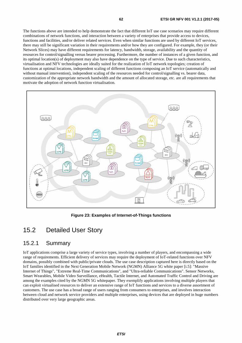
ETSI
ETSI GR NFV 001 V1.2.1 (2017-05)62
The functions above are intended to help demonstrate the fact that different IoT use case scenarios may require different combinations of network functions, and interaction between a variety of enterprises that provide access to devices, functions and facilities, and/or deliver related services. Even when similar functions are used by different IoT services, there may still be significant variation in their requirements and/or how they are configured. For example, they (or their Network Slices) may have different requirements for latency, bandwidth, storage, availability and the quantity of resources for control/signalling versus bearer processing. Furthermore, the number of instances of a given function, and its optimal location(s) of deployment may also have dependence on the type of service. Due to such characteristics, virtualisation and NFV technologies are ideally suited for the realization of IoT network topologies; creation of functions at optimal locations, independent scaling of different functions composing an IoT service (automatically and without manual intervention), independent scaling of the resources needed for control/signalling vs. bearer data, customization of the appropriate network bandwidth and the amount of allocated storage, etc. are all requirements that motivate the adoption of network function virtualisation.
Figure 23: Examples of Internet-of-Things functions
15.2 Detailed User Story
15.2.1 Summary
IoT applications comprise a large variety of service types, involving a number of players, and encompassing a wide range of requirements. Efficient delivery of services may require the deployment of IoT-related functions over NFV domains, possibly combined with public/private clouds. The use case description captured here is directly based on the IoT families identified in the Next Generation Mobile Network (NGMN) Alliance 5G white paper [i.5]: "Massive Internet of Things", "Extreme Real-Time Communications", and "Ultra-reliable Communications". Sensor Networks, Smart Wearables, Mobile Video Surveillance, eHealth, Tactile Internet, and Automated Traffic Control and Driving are among the examples cited by the NGMN 5G whitepaper. They exemplify applications involving multiple players that can exploit virtualised resources to deliver an extensive range of IoT functions and services to a diverse assortment of customers. The use case has a broad range of users ranging from consumers to enterprises, and involves interaction between cloud and network service providers and multiple enterprises, using devices that are deployed in huge numbers distributed over very large geographic areas.
ETSI
ETSI GR NFV 001 V1.2.1 (2017-05)63
Smart City can serve as a good example for illustrating the different aspects of the IoT use case. A variety of sensor/data capture devices and remotely-controllable equipment may be deployed for diverse purposes such as monitoring traffic and road conditions, keeping track of street parking spaces, monitoring of moisture in parks and gardens, security camera video streaming, control of traffic lights, operation of irrigation systems, etc. The devices may be connected in different ways: some may be of the SIM-based wireless variety, others may be connected through wireline, WiFi, or capillary networks. As tenants of CSP:NPs, IoT service providers can fill several roles and offer services in a variety of ways such as:
• Install and maintain arrays of devices and provide data and administrative access to their respective customers via APIs exposed through VNFs.
• Use CSP:NP virtualised infrastructure to offer services for storage, management, and delivery of IoT data.
• Provide VNFs to facilitate administrative control of IoT devices for third-party enterprises, e.g. for management of SIM-based equipment subscriptions, group access privilege configuration, etc.
• Use the CSP:NP's PaaS to provide services based on the processing of the IoT data, such as extraction of patterns or other specific information from sensor data, monitoring of security video streams, operation of remotely-controlled devices based on the analysis of collected data, etc. Furthermore, the same data could be used by different entities who may provide different services, or similar competing services.
As the example above shows, IoT use cases typically require the combination of services offered by multiple service providers, resulting in the need for shared access by separate entities, sometimes concurrently, to virtualised functions, services, and infrastructure supplied by one or more CSP:NPs, reaching beyond national borders and spanning multiple legal jurisdictions.
15.2.2 Actor(s)
The use case has a variety of actors some of whom may need to use the same resources, at times simultaneously.
• End-User: Organizations (or consumers) using sensor data.
• Cloud Service Customer (CSC): Takes on the role defined in clause 5 of the present document. For IoT, there can be a mix of entities/enterprises acting in different roles such as:
- Enterprises that make sensors and other IoT devices available to other CSCs, possibly through virtualised functions and APIs that provide streaming, monitoring and potentially control/configuration access to the array of devices.
- Enterprises that provide services or functions to other entities, to facilitate device connectivity, management of access/administrative control of the arrays of devices.
- Enterprises that facilitate the storage and retrieval of data.
- Entities that process telemetry/sensor data to extract information to be offered to end-users and/or other CSCs.
NOTE: Some enterprises may embody the combination of some of the roles above, e.g. provide collection, storage, as well as processing of the data.
• Cloud Service Provider: Network Provider (CSP:NP): Takes on the role defined in clause 5 of the present document.
15.2.3 Pre-Conditions
The following pre-conditions apply:
• CSCs are registered with CSPs, or respective CSCs, and are assigned the access points and services corresponding to their specific requirements and profiles.
• End-Users are registered with CSCs, and their identities are linked to the appropriate group(s) of sensors/devices.
• The devices are configured and activated, ready to be operated, and/or to furnish data in appropriate intervals.
ETSI
ETSI GR NFV 001 V1.2.1 (2017-05)64
• CSP:NP has several tenants, among which:
- A is a smart home IoT service provider and has a network of sensors that are monitored by A's service that is deployed in a VNFaaS model using the CSP:NP.
- B is a smart city service provider and has several IoT applications running on the CSP:NP's exposed IoT platform, using the PaaS deployment model. Large data centres, multi-site deployments are typical for tenant B.
- C is a vehicle manufacturer and has monitoring and analytics systems using the CSP:NP's NFV Infrastructure (NFVIaaS).
- D is the governmental organization responsible for environmental issues and which is using their own applications deployed in the CSP:NP's VNFs, but which have several regulatory constraints on the location of the VNFs and their allocated resources.
15.2.4 Begins When
The use case can begin in a number of ways, such as:
• Sensors wake up according to a pre-determined schedule to transmit data.
• Sensors transmit data triggered by an event, or activated by a CSC or an end-user.
• A CSC data base is accessed by an End-user to retrieve recorded data.
• A CSC (or an End-User) initiates events that may send data towards the sensors and/or actuators (e.g. for s/w upgrade, configuration, control).
15.2.5 Description
Once the use case is started, a typical sequence of actions may be as follows:
1) The sensors/devices need to be authenticated by the servers hosting the authentication applications.
2) The end-users need to be authenticated.
3) The flow of data has to be enabled between the devices and the CSCs performing collection and storage, for collection and storage, and end-users or end-user applications.
The actions need to be taken in a manner that guarantees compliance with Data Sovereignty regulations. These regulations are aimed at subjecting the treatment of data to the laws of the country of origin, and can impose strict requirements on aspects such as the location of storage or processing nodes, as well as the routes used for the transport of data from the point of origin to the destination.
15.2.6 End When
The use case ends when the transfer of data is completed.
15.2.7 Post-Conditions
Detailed records reflecting the usage of network resources is made available to the CSCs.
15.2.8 Exceptions
The following exceptions have been identified:
• Insufficient resources are present to support the requested activity. This may be due to, for example, too many events getting triggered at the same time.
• Access violation in cases where the service request may violate regulations (e.g. data residency).
ETSI
ETSI GR NFV 001 V1.2.1 (2017-05)65
15.2.9 Virtualisation target
All traditional network functions used for providing Internet of Things (e.g. connectivity, authentication, storage, gateway) are candidates for virtualisation. Functions that provide access and control interfaces to IoT devices are particularly well suited for virtualisation, and some have critical dependence on the high grade of service that NFV technologies can provide.
IoT can make use of various deployment models, in single or multi-site, over multiple administrative domains, multi-tenancy, etc.
15.3 Coexistence of Virtualised and Non-Virtualised Network Functions
IoT could include a mix of virtualised and non-virtualised network functions. For this use case the coexistence of virtualised and non-virtualised network functions is not anticipated to give rise to specific problems since the functions are generally linked through standard interfaces.
15.4 Problem description/Issues The IoT use case presents the following virtualisation challenges:
• Different end-users and CSCs may need to access the same resources (e.g. storage, sensor arrays), at times simultaneously.
• Data Sovereignty regulations impose restrictions such as prohibiting scale-out of resources to infrastructure domains located in other legal jurisdictions.
• In the case of mobile data sources, Data Sovereignty regulations may require dynamic control/adjustment of data transport routes to ensure the restriction of passage within approved jurisdictions.
• Massive Internet of Things implies simultaneous access and data transmission spread out over vast geographic areas, possibly spanning different NSP and CSP domains.
• The demand for the services, which may entail huge traffic magnitudes and geographies spanning multiple domains, can be sudden and without prior indication.
16 Use Case #11: Rapid Service Deployment
16.1 Motivation This Use case illustrates the high level NFV Objectives and can be applied across a variety of fields of application. This use cases provide a mechanism to determine whether proposed systems meet the business level objectives.
Rapid service innovation through software-based deployment and operationalization of network functions and end-end services is a primary business objective of NFV.
NOTE: See e.g. Business objectives identified in ETSI GS NFV 001 [i.15] and Operator's NFV Whitepaper [i.8].
16.2 Detailed User Story
16.2.1 Summary
By deploying services using software components (VNFs) on a common NFVI, the time to deploy a service instance is dramatically reduced compared to physical installation. If the service is internal to the operator, it may be triggered electronically through some workflow business support system. If the service is customer facing, it may be triggered through a customer facing portal.
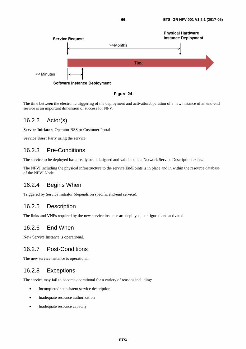
ETSI
ETSI GR NFV 001 V1.2.1 (2017-05)66
Figure 24
The time between the electronic triggering of the deployment and activation/operation of a new instance of an end-end service is an important dimension of success for NFV.
16.2.2 Actor(s)
Service Initiator: Operator BSS or Customer Portal.
Service User: Party using the service.
16.2.3 Pre-Conditions
The service to be deployed has already been designed and validated.ie a Network Service Description exists.
The NFVI including the physical infrastructure to the service EndPoints is in place and in within the resource database of the NFVI Node.
16.2.4 Begins When
Triggered by Service Initiator (depends on specific end-end service).
16.2.5 Description
The links and VNFs required by the new service instance are deployed, configured and activated.
16.2.6 End When
New Service Instance is operational.
16.2.7 Post-Conditions
The new service instance is operational.
16.2.8 Exceptions
The service may fail to become operational for a variety of reasons including:
• Incomplete/inconsistent service description
• Inadequate resource authorization
• Inadequate resource capacity
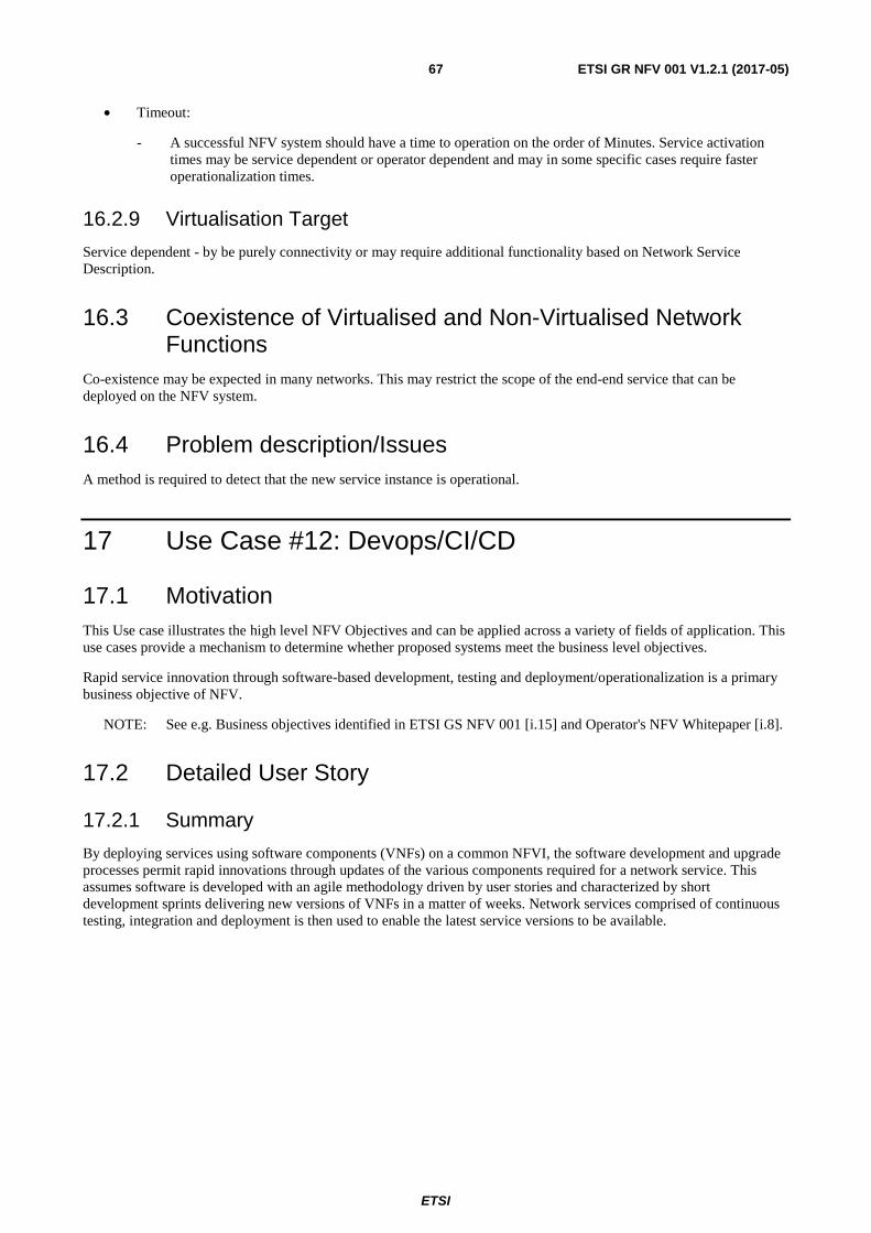
ETSI
ETSI GR NFV 001 V1.2.1 (2017-05)67
• Timeout:
- A successful NFV system should have a time to operation on the order of Minutes. Service activation times may be service dependent or operator dependent and may in some specific cases require faster operationalization times.
16.2.9 Virtualisation Target
Service dependent - by be purely connectivity or may require additional functionality based on Network Service Description.
16.3 Coexistence of Virtualised and Non-Virtualised Network Functions
Co-existence may be expected in many networks. This may restrict the scope of the end-end service that can be deployed on the NFV system.
16.4 Problem description/Issues A method is required to detect that the new service instance is operational.
17 Use Case #12: Devops/CI/CD
17.1 Motivation This Use case illustrates the high level NFV Objectives and can be applied across a variety of fields of application. This use cases provide a mechanism to determine whether proposed systems meet the business level objectives.
Rapid service innovation through software-based development, testing and deployment/operationalization is a primary business objective of NFV.
NOTE: See e.g. Business objectives identified in ETSI GS NFV 001 [i.15] and Operator's NFV Whitepaper [i.8].
17.2 Detailed User Story
17.2.1 Summary
By deploying services using software components (VNFs) on a common NFVI, the software development and upgrade processes permit rapid innovations through updates of the various components required for a network service. This assumes software is developed with an agile methodology driven by user stories and characterized by short development sprints delivering new versions of VNFs in a matter of weeks. Network services comprised of continuous testing, integration and deployment is then used to enable the latest service versions to be available.
ETSI
ETSI GR NFV 001 V1.2.1 (2017-05)68
Figure 25
The cycles times for VNFs and end Services are much shorter than for traditional approaches.
17.2.2 Actor(s)
Service Operator: An operator of an end-end service.
Service Integrator: An entity integrating multiple components required for an end-end service. May be an open source community (e.g. OPNFV).
VNF/Infrastructure Software Provider: Software development entity - may be proprietary or an open source community (e.g. OpenStack).
17.2.3 Pre-Conditions
The NFVI including the physical infrastructure to the service EndPoints is in place and in within the resource database of the NFVI Node.
A service to be deployed has already been designed and validated.ie a Network Service Description exists.
The Service relies on components from one or more VNF/Infrastructure Software Providers.
17.2.4 Begins When
A new version of a software component become available.
17.2.5 Description
The VNF/Infrastructure software provider releases a new version.
The Service Integrator verifies portability over an expected range of NFVI implementations and interoperability with an expected range of other service components.
The Service Operator validates operation within VNFD Performance benchmarks, and expected service configurations.
17.2.6 End When
New Service Instance is operational with the new software component.
17.2.7 Post-Conditions
The new service instance is operational.
ETSI
ETSI GR NFV 001 V1.2.1 (2017-05)69
17.2.8 Exceptions
The service may fail to become operational for a variety of reasons including:
• Incomplete/inconsistent software description
• Inadequate software performance
• Inadequate software portability
• Integration testing errors
17.2.9 Virtualisation Target
Not applicable. This is a process that applies across multiple virtualisation targets.
17.3 Coexistence of Virtualised and Non-Virtualised Network Functions
Co-existence may be expected in many networks. This may restrict the scope of the end-end service that can be deployed on the NFV system.
17.4 Problem description/Issues A method is required to pass software defects upstream.
Software may be partially operational, but with some feature limitations - e.g. a feature provided within a VNF may be disabled within a network service.
18 Use Case #13: A/B testing
18.1 Motivation This Use Case illustrates the high level NFV Objectives and can be applied across a variety of fields of application. This use cases provide a mechanism to determine whether proposed systems meet the business level objectives.
Rapid service innovation through software-based development, testing and operationalization of end-end services is a primary business objective of NFV.
NOTE: See e.g. Business objectives identified in ETSI GS NFV 001 [i.15] and Operator's NFV Whitepaper [i.8].
18.2 Detailed User Story
18.2.1 Summary
With more rapid software deployment, it becomes feasible to test the performance of alternative approaches in both sandboxed and live service environments. VNF alternatives could be VNF updates, VNF substitutes, etc. Network service updates could use alternate paths, VNFs, configurations etc. Using A/B testing approaches the performance of the alternatives could determine which of the variants is the better.
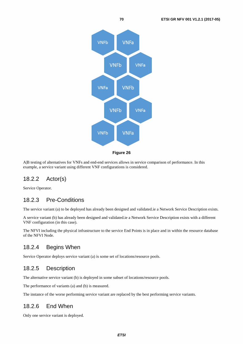
ETSI
ETSI GR NFV 001 V1.2.1 (2017-05)70
Figure 26
A|B testing of alternatives for VNFs and end-end services allows in service comparison of performance. In this example, a service variant using different VNF configurations is considered.
18.2.2 Actor(s)
Service Operator.
18.2.3 Pre-Conditions
The service variant (a) to be deployed has already been designed and validated.ie a Network Service Description exists.
A service variant (b) has already been designed and validated.ie a Network Service Description exists with a different VNF configuration (in this case).
The NFVI including the physical infrastructure to the service End Points is in place and in within the resource database of the NFVI Node.
18.2.4 Begins When
Service Operator deploys service variant (a) is some set of locations/resource pools.
18.2.5 Description
The alternative service variant (b) is deployed in some subset of locations/resource pools.
The performance of variants (a) and (b) is measured.
The instance of the worse performing service variant are replaced by the best performing service variants.
18.2.6 End When
Only one service variant is deployed.
ETSI
ETSI GR NFV 001 V1.2.1 (2017-05)71
18.2.7 Post-Conditions
The best service variant is operational.
18.2.8 Exceptions
The service variant may fail to become operational for a variety of reasons including:
• Incomplete/inconsistent service description
• Inadequate resource authorization
• Inadequate resource capacity
• Timeout:
- The performance results may be inconclusive.
18.2.9 Virtualisation Target
Service dependent - by be purely connectivity or may require additional functionality based on Network Service Description.
18.3 Coexistence of Virtualised and Non-Virtualised Network Functions
Co-existence may be expected in many networks. This may restrict the scope of the end-end service that can be deployed on the NFV system.
18.4 Problem description/Issues The performance objectives should be the same for both service variants. These objectives could be customer facing (e.g. customer satisfaction) or operational (e.g. resource usage) in nature.
19 Use Case #14: VNF composition across multiple administrative domains
19.1 Motivation The progressing immersion into digital economy driven by the industry verticals [i.9], the competition from Over-The-Top (OTT) service providers, the dynamicity introduced by hosting virtualised service functions into the cloud, and the demand of permanent connectivity to digital services are changing the way communication services are provided. Within this business ecosystem, the advent of 5G networks will foster this change, proposing a pervasive availability of access capacity even in ultra-dense population areas. Shorter latency, fast Time-To-Market (TTM) for any kind of service, and a better and consistent quality of experience (independent of the point of attachment to the network) are key aspects to address. The need for this dynamic creation, operation and control of services and resources will be even exacerbated in the access and aggregation areas, where variability of the demand in terms of number of users and their distribution, heterogeneous service requirements (from data intensive residential-like service to flow-intensive machine-to-machine connections), and cost of (own) deployment cannot justify in some cases the huge level of investment needed. The idea of leasing virtualised networking and computing environments is then an option in order to lower the Total Cost of Ownership (TCO), simplify the network architecture, and streamline the operation and their associated costs.
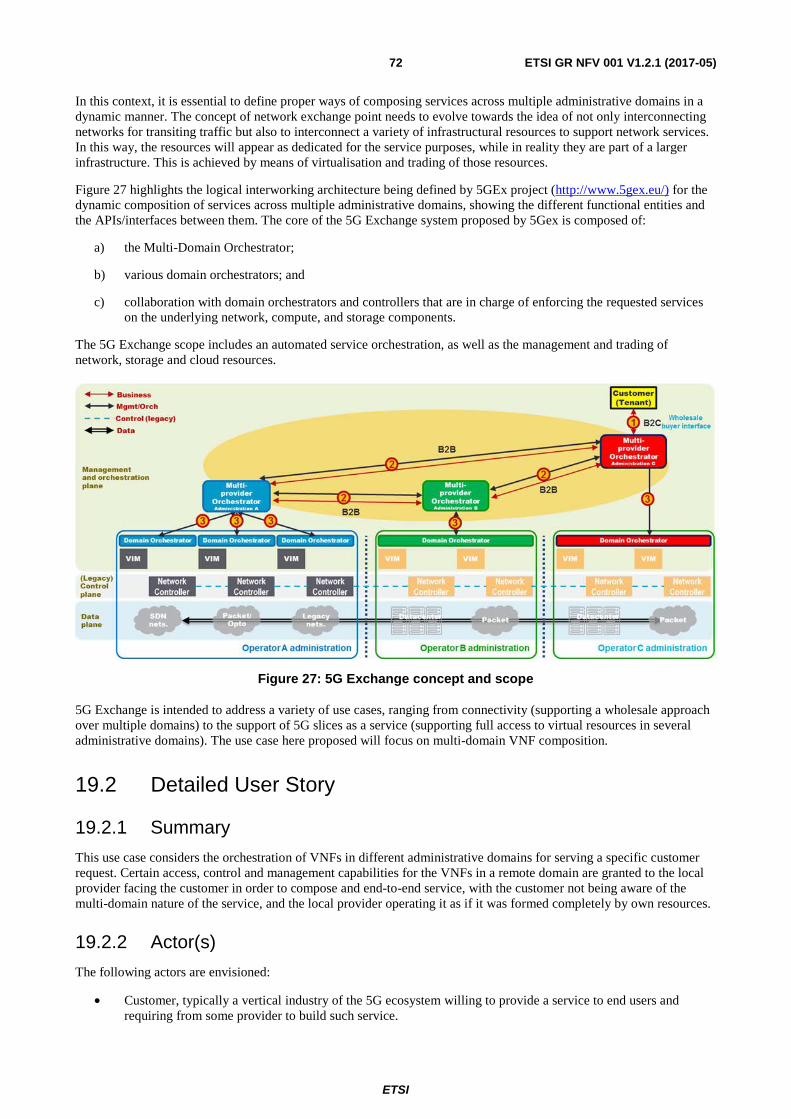
ETSI
ETSI GR NFV 001 V1.2.1 (2017-05)72
In this context, it is essential to define proper ways of composing services across multiple administrative domains in a dynamic manner. The concept of network exchange point needs to evolve towards the idea of not only interconnecting networks for transiting traffic but also to interconnect a variety of infrastructural resources to support network services. In this way, the resources will appear as dedicated for the service purposes, while in reality they are part of a larger infrastructure. This is achieved by means of virtualisation and trading of those resources.
Figure 27 highlights the logical interworking architecture being defined by 5GEx project (http://www.5gex.eu/) for the dynamic composition of services across multiple administrative domains, showing the different functional entities and the APIs/interfaces between them. The core of the 5G Exchange system proposed by 5Gex is composed of:
a) the Multi-Domain Orchestrator;
b) various domain orchestrators; and
c) collaboration with domain orchestrators and controllers that are in charge of enforcing the requested services on the underlying network, compute, and storage components.
The 5G Exchange scope includes an automated service orchestration, as well as the management and trading of network, storage and cloud resources.
Figure 27: 5G Exchange concept and scope
5G Exchange is intended to address a variety of use cases, ranging from connectivity (supporting a wholesale approach over multiple domains) to the support of 5G slices as a service (supporting full access to virtual resources in several administrative domains). The use case here proposed will focus on multi-domain VNF composition.
19.2 Detailed User Story
19.2.1 Summary
This use case considers the orchestration of VNFs in different administrative domains for serving a specific customer request. Certain access, control and management capabilities for the VNFs in a remote domain are granted to the local provider facing the customer in order to compose and end-to-end service, with the customer not being aware of the multi-domain nature of the service, and the local provider operating it as if it was formed completely by own resources.
19.2.2 Actor(s)
The following actors are envisioned:
• Customer, typically a vertical industry of the 5G ecosystem willing to provide a service to end users and requiring from some provider to build such service.
ETSI
ETSI GR NFV 001 V1.2.1 (2017-05)73
• Provider facing the customer, which maintains direct commercial relationship with the customer and receives the service request to be honoured. This provider will be also referred to as local provider to differentiate from the other providers in the Exchange.
• Remote provider(s), able to complement the service offer of the customer facing provider.
Multiple providers are assumed to maintain simultaneous trusted commercial relationships in open environments like an evolved network exchange point, in some cases playing a specialized role (e.g. infrastructure service providers, connectivity service providers, etc.). For the generalization of this use case at this stage no further differentiation other than local and remote provider is here considered.
19.2.3 Pre-Conditions
The following pre-conditions apply for the local and the remote administrative domains, respectively.
For the local administrative domain:
• One or more NS descriptions have been created with identification of VNFs from local and remote administrative domains.
• The Multi-Domain Orchestrator of the local provider has access to the interfaces of providers in remote administrative domains for the instantiation of the necessary NSs/VNFs.
• The Multi-Domain Orchestrator of the local provider is able to configure the VNFFG(s) described by the requested NSs , interacting when required with the remote administrative domains.
• The Multi-Domain Orchestrator of the local provider is able to provide initial configuration data to the VNFs composing a service instance , regardless the location of the elements, as a tenant in the remote provider infrastructure duly isolated from all the other tenants outside the VNF perimeter.
For the remote administrative domain:
• The Multi-Domain Orchestrator of the remote provider is able to configure traffic steering to, from and between VNFs instantiated for the service, according to the instructions received by the originating administrative domain.
• The Multi-Domain Orchestrator of the remote provider supports adjusting resource capacity allocated to a VNF on request from the originating administrative domain.
19.2.4 Begins When
The use case is triggered when a customer service request (e.g. a vertical industry, an OTT, a MVNO, etc.) to a provider cannot be served with own resources only. In that situation, the provider will interact with other providers (e.g. participating in an exchange environment), to trade the necessary resources and capabilities to honour the customer's request. The final service composition will involve resources and capabilities from different administrative domains, by using the mechanisms like the ones provided by the 5G Exchange.
19.2.5 Description
The steps considered in this use case are as follows:
• The customer (i.e. a 5G vertical industry) solicits the deployment of a service offered by a provider, typically through a service catalog.
• The provider facing the customer will accept the service request and will analyse the requirements and needs derived from such request. As result, this provider identifies one or more NS descriptors that include virtualised resources and/or NFs from remote domains to be able to satisfy the customer demand.
• The provider facing the customer, being participant of the 5G Exchange, based on the negotiation mechanisms in place, and attending to the offers from other remote providers, triggers the request of the necessary resources for complementing the customer's request. Resource Orchestration between administrative domains is implemented.
ETSI
ETSI GR NFV 001 V1.2.1 (2017-05)74
• Once the necessary resources are granted, with access to control and management interfaces as facilitated by the remote provider and proper tenant isolation, the local provider enters on the Service Configuration phase for composing the service end-to-end, in a transparent manner for the customer.
• With the service completely orchestrated, the local provider honours the service to the customer as if it was fully provided with local provider's own resources. At this stage the customer can start using the requested service.
19.2.6 Ends When
The use case ends once the customer's request has been honoured with success, including the desired SLAs. Customers maintain just direct commercial relationship with their provider, being transparent for them the multi-domain composition of the service. The customer in general will not be aware of the multi-domain nature of the service.
19.2.7 Post-Conditions
An exception to the domain transparency described above could be the case of the constraints (e.g. geographical) that could be imposed on the service request.
The assumption of transparency imposes the need for the customer facing provider to control, manage and ensure the required quality of service as if it was served with own resources.
19.2.8 Exceptions
The service cannot be honoured in case the originating provider cannot find in the 5G Exchange environment the necessary resources to complement the service as requested by the customer.
19.2.9 Virtualisation Target
The target of virtualisation applies to whatever function the customer (e.g. a vertical industry) could require for service provision, i.e. DPI, Firewall, SGSN, MME, etc.
The functions to be virtualised will highly depend on the scope of the service and the market targeted by the vertical industry. These physical functions are managed in an application domain specific manner, beyond the scope of ETSI NFV.
19.3 Coexistence of Virtualised and Non-Virtualised Network Functions
Coexistence with non-virtualised functions can be envisioned in both local and remote administrative domains. Some of the components of the service could be implemented as physical network functions, either as part of the customer facing services or the resource facing service [i.10] that could result necessary to honour the customer's request.
The physical functions to participate in the service will highly depend on the scope of the service and the market targeted by the vertical industry.
19.4 Problem description/Issues The following problems and issues could negatively affect the multi-domain service provision across 5GEx:
• Non-common abstracted description of resources that could prevent a common understanding of the customer needs for the requested service.
• The necessary coordination of life cycle management of VNFs and other resources belonging to separated administrative domains.
• There is a need for aggregating alarms, counters, logs, and utilization information in a consistent way among the participating domains, as well as to facilitate the control of the service (even for the remotely provided resources) to the customer as it was negotiated.
ETSI
ETSI GR NFV 001 V1.2.1 (2017-05)75
• Different SLA metrics among providers in 5GEx that could avoid a proper mapping of the service guarantees to be fulfilled.
• Lack of proper control and management interfaces to dictate actions in the VNFs offered by the remote domain (e.g. control the application-level behaviour of the function running in the VNF). This is, in general, to be specified by the body responsible for the application domain and therefore beyond the scope of NFV.
20 Use Case #15: Security as a Service (SecaaS)
20.1 Motivation Protection against online incidents and cybercrime has become central to consumer confidence and enterprise businesses, hence to the online economy. As cybercrime grows, attacks evolve and get more complex forcing organizations to continuously update their cybersecurity and cyber-defence techniques. This process is costly and usually not fast enough to effectively cope with continuous new ranges of attacks and cyber threats.
It is expected that this situation will be worsen in the future. The reasons are several:
• Ultrabroadband. FTTx, 5G networks, are providing high bandwidth capacity to multiple devices and access networks. It is already common to provide GPON access over 100 Mbps for residential customers, which can be weaponized as DDoS tools.
• Massive IoT deployments. IoT devices in number are moving to billions. The main features of these devices are heterogeneity, low cost and lack of upgrades. As a consequence IoT has started to show multiple vulnerabilities to be exploited to access sensitive resources and data.
• Enterprise technology and Internet dependency. Lots of enterprises, especially small ones are increasing their presence on the networks or are born as Internet-oriented business. Protection from security risks are beyond their resource by themselves, what makes them perfect victims for cybercrime.
This context is demanding technological solutions and services to provide effective protection in a rapidly changing threat environment. The NFV technology can provide solutions especially for specific VNF type like vNSF or Virtual Network Security Function. A business opportunity exist in addressing a Security as a Service (Secaas) approach. A service based on NFV orchestration that deploy security protection by means of VNFs can offer:
• Dynamic and tailored response for any kind of security threat solvable in the network through specifics VNFs.
• Scalability of resources beyond the enterprise capabilities in a per-use model.
• Targeted security data monitoring and gathering at specific points in the network, for intelligent analysis and remediation.
20.2 Detailed User Story
20.2.1 Summary
As aforementioned, the main idea is building enhanced SecaaS services, leveraging NFV technologies. Using this SecaaS paradigm, the complexity of the security analysis can be hidden from ISP customers, freeing them from the need to acquire, deploy, manage and upgrade specialized security equipment.
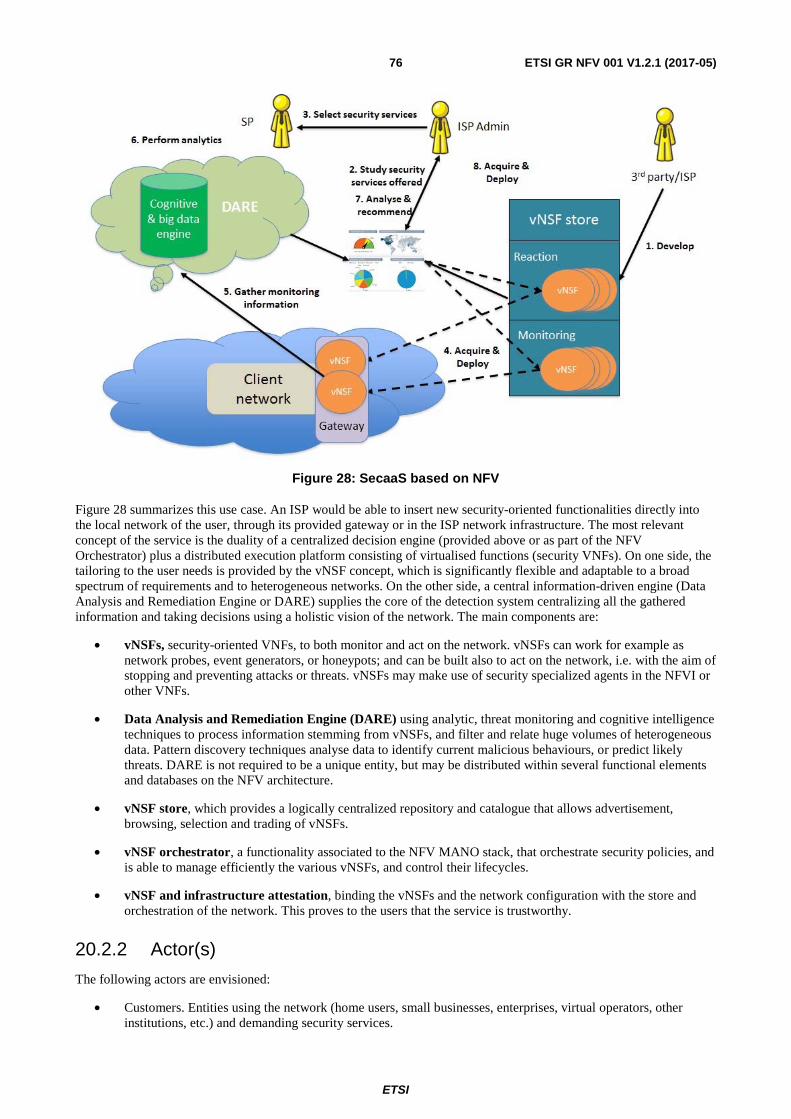
ETSI
ETSI GR NFV 001 V1.2.1 (2017-05)76
Figure 28: SecaaS based on NFV
Figure 28 summarizes this use case. An ISP would be able to insert new security-oriented functionalities directly into the local network of the user, through its provided gateway or in the ISP network infrastructure. The most relevant concept of the service is the duality of a centralized decision engine (provided above or as part of the NFV Orchestrator) plus a distributed execution platform consisting of virtualised functions (security VNFs). On one side, the tailoring to the user needs is provided by the vNSF concept, which is significantly flexible and adaptable to a broad spectrum of requirements and to heterogeneous networks. On the other side, a central information-driven engine (Data Analysis and Remediation Engine or DARE) supplies the core of the detection system centralizing all the gathered information and taking decisions using a holistic vision of the network. The main components are:
• vNSFs, security-oriented VNFs, to both monitor and act on the network. vNSFs can work for example as network probes, event generators, or honeypots; and can be built also to act on the network, i.e. with the aim of stopping and preventing attacks or threats. vNSFs may make use of security specialized agents in the NFVI or other VNFs.
• Data Analysis and Remediation Engine (DARE) using analytic, threat monitoring and cognitive intelligence techniques to process information stemming from vNSFs, and filter and relate huge volumes of heterogeneous data. Pattern discovery techniques analyse data to identify current malicious behaviours, or predict likely threats. DARE is not required to be a unique entity, but may be distributed within several functional elements and databases on the NFV architecture.
• vNSF store, which provides a logically centralized repository and catalogue that allows advertisement, browsing, selection and trading of vNSFs.
• vNSF orchestrator, a functionality associated to the NFV MANO stack, that orchestrate security policies, and is able to manage efficiently the various vNSFs, and control their lifecycles.
• vNSF and infrastructure attestation, binding the vNSFs and the network configuration with the store and orchestration of the network. This proves to the users that the service is trustworthy.
20.2.2 Actor(s)
The following actors are envisioned:
• Customers. Entities using the network (home users, small businesses, enterprises, virtual operators, other institutions, etc.) and demanding security services.
ETSI
ETSI GR NFV 001 V1.2.1 (2017-05)77
• Network Operators that use (and in many cases own) the NFVI, and provide network services.
• Developers and third parties. They can publish security virtual network functions, that will be selected for deployment by interested customers through the vNSF store.
These are general roles that can be further specialized. Third-party developers can be companies with specific business agreements with network operators or NFVI providers, but as well security agencies that create their specific VNFs, or internal departments within an operator.
20.2.3 Pre-Conditions
The initial pre-conditions require the global architecture for SecaaS deployed, including the following:
• Operator with a NFV compatible architecture deployed, including NFV MANO integrated with OSS/BSS and DARE. vNSF Store and orchestrator integrated with it.
• Monitoring and dashboard tools, as part of a SOC (Security Operative Centre), or a Dashboard tool access for the customer. The latter will allow the customer decide some actions.
• A set of datacentres or PoPs (Point of Presence) with NFVI enabled and the necessary network connectivity. In some situations part of the NFVI can be located at the customer premises.
• A set of vNSFs and/or security VNF developers that are able to cover the security customer demands: anti-DDoS, data leakage protection, traffic identification, honeynet, etc.
20.2.4 Begins When
The user case starts when a customer requests an initial service subscription, based on the suspicious of a security incident or as part of their risk assessment and security plan. As a result, the customer has an initial idea of what kind of vNSF to demand.
20.2.5 Description
The steps considered in this use case are included in Figure 1. The process is as follows:
1) Develop: The vNSFs in this case can be developed by either the operator or by a third party (vNSF developer). Once the vNSFs are developed and tested they can be deployed to the vNSF store.
2) Analyse the offered security services: The customer analyses the service offer, based on the pre-condition situation studies, using the dashboard or via OSS/BSS and the operator's commercial channels, the security services offered by the SP.
3) Select security services: The customer selects the desired security services.
4) Acquire and deploy: The customer deploys, using a dashboard or via OSS/BSS and the operator's commercial channels, the selected services, which may consist of one or more vNSFs that are located at the PoP of its NFVI infrastructure, or at the customer premises if demanded. It is a NFV on-demand service, and the NFV Orchestrator will translate the OSS/BSS demands in a dynamic deployment.
5) Gather monitoring information: Deployed vNSF sends monitoring information to the DARE which firstly acquires and validates it, and finally stores and process such information.
6) Perform analytics: The DARE processes the information according to the needs of the security services purchased by the customer.
7) Analyse and recommend: The dashboard provides the customers with monitoring data from the deployed security services. Moreover, the engine decides if there are further actions to be performed according to the threats analysed and the security requirements of the customer.
8) Acquire and deploy: Depending on the recommendations and the security requirements, more vNSFs can be deployed in the infrastructure to protect the customer.
ETSI
ETSI GR NFV 001 V1.2.1 (2017-05)78
20.2.6 Ends When
The previous process ends when a mitigation is applied through a vNSF and the customer receives detailed information of the result of the process through the dashboard, e.g. a mitigation action performed by a vNSF. In another situation, the use case can be a continuous monitoring service based on a vNSF and only ends when the customer unsubscribes the service and the vNSF is removed by the orchestrator.
20.2.7 Post-Conditions
The expected post-condition is a security service in place to accomplish customer demands. It will include:
• One or more vNSFs and the associated service graph deployed in the customer PoP or premises.
• The specific security policy associated to the customer demand.
• The final status of the deployment and the data info provided by the vNSF, e.g.: security alerts. This information is delivered to the customer through a Dashboard.
• The attestation report that allows customer to trust the deployment done.
20.2.8 Exceptions
It could happen that some vNSFs cannot be deployed in some situations. Oversubscription, lack of some NFVI resources in a specific PoP or datacentre, are some examples. As a result, the customer and/or ISP will be informed of the exception through the orchestrator and the process can be programmed for additional attempts or reallocation of resources. This information is delivered to the Dashboard.
20.2.9 Virtualisation Target
The target of virtualisation applies to the different appropriate vNSFs, and the high variety of potential customers that can demand the execution of security functionality as-a-service. The virtualisation target therefore includes practically any potential security demand. Some examples of the most common categories are:
• Access control, containing the set of capabilities to filter and restrict the traffic based on a list of conditions.
• Anti-malware, for detection and eradication of malicious traffic, including the discovery of bot infections, the detection of unsolicited traffic, and the identification of malware in network traffic.
• Privacy, providing mechanisms to enhance privacy to user traffic, such as the traffic anonymization, encrypted links, or data leakage prevention.
• Auditor, with capabilities to help the users discover threats in their local environment. Examples of these capabilities are traffic record, vulnerabilities scanner, software inventory, or honeynets.
• Network monitoring, implementing the analysis of the traffic flowing through the network looking for threats, such as Network Intrusion Detection System (IDS) or Network Intrusion Prevention System (IPS).
• Legal, helping service providers to comply to legal requirements. The most relevant one is Lawful Interception.
20.3 Coexistence of Virtualised and Non-Virtualised Network Functions
Coexistence between virtualised and non-virtualised function will be managed through the OSS/BSS. Some of the non-virtualised functions like Backbone routers, physical switches, access nodes, will have their EMS (Element Management Systems) integrated with the OSS/BSS, in order to deploy the traffic flows to the vNSF from the client and to internet connection. A integration between the EMS and vNSF orchestrator through the OSS/BSS is expected.
ETSI
ETSI GR NFV 001 V1.2.1 (2017-05)79
20.4 Problem description/Issues Some problems envisioned in this use case are:
• Geolocation of NFVI resources with customer demands, which can generate service degradation or unavailability if customer is associated to a physical location with not enough resources.
• Performance isolation between customers, which could be an issue, especially in some security services that protect for resource consumption attacks, i.e. DDoS.
• Deployment options at customer premises could be challenging, as they will limit NFVI resource optimization. They also could imply a security risk by extending orchestration operations into the customer network.
• Data aggregation and processing at the DARE functional elements has to be performed preserving customer privacy and guaranteeing tenant isolation in multi-tenant NFVI scenarios.

ETSI
ETSI GR NFV 001 V1.2.1 (2017-05)80
Annex A: Change History
Date Version Information about changes October 2013 1.1.1 First publication after approval.
April 2017 1.2.1
The Use Case Description uses a new template. An additional set of Use Cases has been added, existing ones has been updated (according to the new use case template) and two obsolete use cases have been removed. The document type has been revised into a Group Report.

ETSI
ETSI GR NFV 001 V1.2.1 (2017-05)81
History
Document history
V1.1.1 October 2013 Publication as ETSI GS NFV 001
V1.2.1 May 2017 Publication