etl integrator user’s guideetl integrator user’s guide 12 seebeyond proprietary and confidential...
TRANSCRIPT
eTL Integrator User’s Guide
Release 5.0.3
SeeBeyond Proprietary and Confidential

The information contained in this document is subject to change and is updated periodically to reflect changes to the applicable software. Although every effort has been made to ensure the accuracy of this document, SeeBeyond Technology Corporation (SeeBeyond) assumes no responsibility for any errors that may appear herein. The software described in this document is furnished under a License Agreement and may be used or copied only in accordance with the terms of such License Agreement. Printing, copying, or reproducing this document in any fashion is prohibited except in accordance with the License Agreement. The contents of this document are designated as being confidential and proprietary; are considered to be trade secrets of SeeBeyond; and may be used only in accordance with the License Agreement, as protected and enforceable by law. SeeBeyond assumes no responsibility for the use or reliability of its software on platforms that are not supported by SeeBeyond.
SeeBeyond, e*Gate, and e*Way are the registered trademarks of SeeBeyond Technology Corporation in the United States and select foreign countries; the SeeBeyond logo, e*Insight, and e*Xchange are trademarks of SeeBeyond Technology Corporation. The absence of a trademark from this list does not constitute a waiver of SeeBeyond Technology Corporation's intellectual property rights concerning that trademark. This document may contain references to other company, brand, and product names. These company, brand, and product names are used herein for identification purposes only and may be the trademarks of their respective owners.
© 2003 by SeeBeyond Technology Corporation. All Rights Reserved. This work is protected as an unpublished work under the copyright laws.
This work is confidential and proprietary information of SeeBeyond and must be maintained in strict confidence.
Version 20040303103909.
eTL Integrator User’s Guide 2 SeeBeyond Proprietary and Confidential
Contents
Contents
Chapter 1
System Description 6Introduction 6
The eTL Integrator Product Description 6The ETL Process 7
eTL Supporting Features 8
Supporting Documents 10
Writing Conventions 11Additional Conventions 11
Installing eTL 12Installing eTL on an eGate Supported System 12
The SeeBeyond Web Site 12
Chapter 2
Graphical Interface Tools 13Toolbar Icons for eTL Collaborations 13
Using Operators 15
Comparison Toolbar Icons—Operators 16
Boolean Toolbar Icons—Operators 19
Number Toolbar Icons—Operators 20
SQL Toolbar Icons—Operators 23
String Toolbar Icons—Operators 25
Chapter 3
Interface to the eGate Enterprise Designer 27Enterprise Designer Components 27
Menu Bar 28
Enterprise Explorer 29
eTL Integrator User’s Guide 3 SeeBeyond Proprietary and Confidential
Contents
Project Editor 29Creating Database OTDs 29Importing Metadata Information for Flat files 31
Chapter 4
Extraction Filters and Implementation Conditions 40Using Runtime Filters 40
Configuring Inserts and Updates 40Input and Output Runtime Arguments 41Conditional Extractions 43Optional Method for Selecting Tables 46
Using Operators - Parenthesis 47
Chapter 5
Creating a Sample Project Using Flatfiles 49Sample Scenario Data 49
Create and Name a Project 51Create a New Object Type Definition 51Create a Collaboration Definition 56
Mapping Tables 58Map Tables and Add a Join Condition 58Apply Business Logic 62Validating and Testing 63
Connectivity Map 64Create a Connectivity Map 64
Deployment Profile for eTL 66Run your Project 67
Run the Bootstrap and Management Agent 68Run the Bootstrap 68
Verify the Output Data 69
Chapter 6
Creating a Sample Project 70Sample Scenario Using Oracle 70
Starting the Enterprise Designer 71Create and Name a Project 71Create a New Object Type Definition 72Select Database Objects 74Use Enterprise Designer to configure eTL Collaborations 79Optional Method for Selecting Tables 82
eTL Integrator User’s Guide 4 SeeBeyond Proprietary and Confidential
Contents
Mapping Tables Using Join Views 84Join Two Tables 84Join More Than Two Tables 89
Validating and Testing 92Validate Collaboration 93Execute a Test Run 93
Appendix A
Using eTL With eInsight 94Using eTL With eInsight 94
Glossary 99e*Gate 4.x Terms in eGate 5.0 105
Index 107
eTL Integrator User’s Guide 5 SeeBeyond Proprietary and Confidential
Chapter 1 Section 1.1System Description Introduction
Chapter 1
System Description
SeeBeyond’s eTL Integrator technology is optimized for very large record sets and build data scenarios that are fully integrated with the SeeBeyond ICAN suite (Integrated Composite Application Network Suite) to unify the domains of eAI (eBusiness and Application Integration) and ETL. An eTL Collaboration can be integrated into the enterprise business process or used as a standalone ETL process.
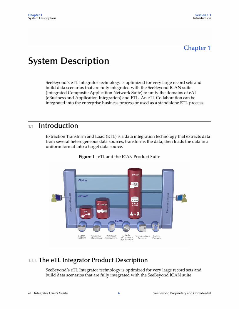
1.1 IntroductionExtraction Transform and Load (ETL) is a data integration technology that extracts data from several heterogeneous data sources, transforms the data, then loads the data in a uniform format into a target data source.
Figure 1 eTL and the ICAN Product Suite
1.1.1. The eTL Integrator Product Description
SeeBeyond’s eTL Integrator technology is optimized for very large record sets and build data scenarios that are fully integrated with the SeeBeyond ICAN suite
eTL Integrator User’s Guide 6 SeeBeyond Proprietary and Confidential
Chapter 1 Section 1.1System Description Introduction
(Integrated Composite Application Network Suite) to unify the domains of eAI (eBusiness and Application Integration), and Enterprise Information Integration (EII). With these unified domains you can build unprecedented solutions using both message based processing (eGate) and dataset based processing (eTL) technologies.
The eTL Integrator product provides excellent performance at runtime for high volume extraction and load of tabular data sets. The eTL Integrator can be integrated into the enterprise business processes or used as a standalone product.
The eTL Integrator product can be used to acquire a temporary subset of data for reports or other purposes, or acquire a more permanent data set for the population of a data mart or data warehouse. The product may also be used for conversion of one database type to another or for the migration of data from one database or platform to another.
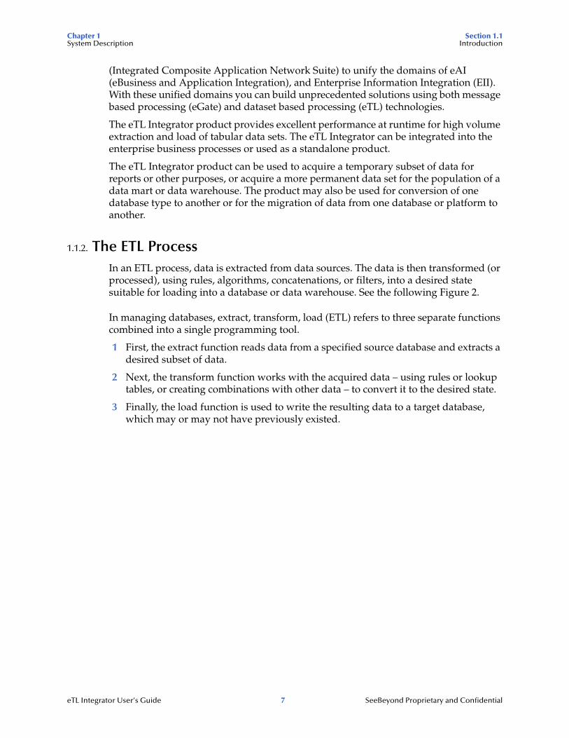
1.1.2. The ETL ProcessIn an ETL process, data is extracted from data sources. The data is then transformed (or processed), using rules, algorithms, concatenations, or filters, into a desired state suitable for loading into a database or data warehouse. See the following Figure 2.
In managing databases, extract, transform, load (ETL) refers to three separate functions combined into a single programming tool.
1 First, the extract function reads data from a specified source database and extracts a desired subset of data.
2 Next, the transform function works with the acquired data – using rules or lookup tables, or creating combinations with other data – to convert it to the desired state.
3 Finally, the load function is used to write the resulting data to a target database, which may or may not have previously existed.
eTL Integrator User’s Guide 7 SeeBeyond Proprietary and Confidential
Chapter 1 Section 1.2System Description eTL Supporting Features
Figure 2 The ETL Process
1.2 eTL Supporting FeatureseTL Integrator is compatible with the following systems and platforms:
! Oracle 8.1.7 and 9i (9.0.2), SQL Server 2000, DB2 UDB 8.1, and tabular formatted flat files
! Multiple sources and multiple destinations
! Standard eGate platform support
Built in Integration Capability
eTL Integrator enables seamless filtering and data transformation.
! Merge/upsert (updates or inserts as appropriate)
! Drag and drop GUI design features (create joins across disparate data sources)
! Validate Collaborations before performing the ETL processes (ICAN Suite provides versioning and history)
Design Tools
User friendly, state-of-the-art, design tools reduce development time and cost.
Extract Transform
Extract data froma source
Process through a seriesof transformations
Load data into a target/warehouse
Load
Warehouse
eTL Integrator User’s Guide 8 SeeBeyond Proprietary and Confidential
Chapter 1 Section 1.2System Description eTL Supporting Features
The eTL Integrator Collaboration editor has two key characteristics that maximize productivity and ease of use:
1 GUI based Collaboration editor employs drag and drop design features
" User friendly Wizards (easy OTD creation)
" Graphical operators (dragged from a toolbar)
" Graphical tools (create underlying SQL)
2 Tight integration among ICAN Suite business data systems
" Web Services interface
" Seamless integration with the ICAN Suite
Development Tools
Development is simplified with GUI based development tools that are appropriate for SQL Collaborations. Graphical drag and drop modeling tools enable SQL operations in various categories:
! Number
! Comparison
! Boolean
! SQL Specific
! String
Transformation Capability
eTL Integrator provides all of the common operations in the following areas:
! SQL operators
! Mathematical operators
! String manipulations
! Source date format must match the target date format (Date format conversions - later release)
! Conditional data transformations
Architecture
Robust business application integration throughout the ICAN Suite makes eTL a more versatile and powerful tool.
! A deployed eTL engine runs as a JCA compliant (J2EE) resource adapter inside the SeeBeyond Integration server.
! The business rules defined by the eTL Collaboration definition are stored in the SeeBeyond Repository.
! At deployment time, the business rules are used to generate the appropriate platform specific SQL.
! eTL Integrator leverages OTDs defined in the Enterprise Designer so you don’t have to create OTDs specifically for an eTL Collaboration.
eTL Integrator User’s Guide 9 SeeBeyond Proprietary and Confidential
Chapter 1 Section 1.3System Description Supporting Documents
Key Operations and Functionality
An extensive array of operators, filtering, and data manipulation tools offer unlimited data design capability.
! Join
" Auto-detect primary key relationships between tables, as indicated in OTDs
" Between tables from disparate data sources that have no relationship
" Supports inner, left, right, and full outer joins
! Lookups
" Extensive list of operators allows you to create lookups as part of the eTL process, using joins across tables
! Merge
" Automatic update if row exists
" Automatic insert if row doesn’t exist
! Test data and test runs
! Runtime variables (configured by the user)
1.3 Supporting DocumentsThe following SeeBeyond documents provide additional information about eGate Integrator:
! SeeBeyond ICAN Suite Installation Guide
! eGate Integrator Release Notes
! eGate Integrator User’s Guide
! Message Server Reference Guide
! eGate Integrator Tutorial
! SeeBeyond ICAN Suite Deployment Guide
! SeeBeyond ICAN Suite Primer
See the SeeBeyond ICAN Suite Primer for a complete list of eGate Integrator documentation. You can also refer to the appropriate Windows or UNIX documents, if necessary.
eTL Integrator User’s Guide 10 SeeBeyond Proprietary and Confidential
Chapter 1 Section 1.4System Description Writing Conventions
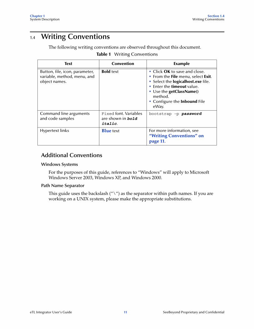
1.4 Writing ConventionsThe following writing conventions are observed throughout this document.
Additional Conventions
Windows Systems
For the purposes of this guide, references to “Windows” will apply to Microsoft Windows Server 2003, Windows XP, and Windows 2000.
Path Name Separator
This guide uses the backslash (“\“) as the separator within path names. If you are working on a UNIX system, please make the appropriate substitutions.
Table 1 Writing Conventions
Text Convention Example
Button, file, icon, parameter, variable, method, menu, and object names.
Bold text ! Click OK to save and close.! From the File menu, select Exit.! Select the logicalhost.exe file.! Enter the timeout value.! Use the getClassName()
method.! Configure the Inbound File
eWay.
Command line arguments and code samples
Fixed font. Variables are shown in bold italic.
bootstrap -p password
Hypertext links Blue text For more information, see “Writing Conventions” on page 11.
eTL Integrator User’s Guide 11 SeeBeyond Proprietary and Confidential
Chapter 1 Section 1.5System Description Installing eTL
1.5 Installing eTLDuring the eGate Integrator installation process, the Enterprise Manager, a web-based application, is used to select and upload products from the eGate installation CD-ROM to the Repository.
When the Repository is running on a UNIX operating system, eGate and eTL are installed using the Enterprise Manager from a computer running Windows, connected to the Repository server.
Refer to the SeeBeyond ICAN Suite Installation Guide.
1.5.1. Installing eTL on an eGate Supported SystemeTL is installed during the installation of the eGate Integrator. The eGate installation process includes the following operations:
! Install the eGate Repository
! Upload products to the Repository
! Download components (such as the SeeBeyond Enterprise Designer and Logical Host)
Follow the instructions for installing the eGate Integrator in the SeeBeyond ICAN Suite Installation Guide, and include the following steps:
1 During the procedures for uploading files to the eGate Repository using the Enterprise Manager, after uploading the eGate.sar file, select and upload the following files:
" eTL.sar
" eTLDocs.sar (to download the eTL Integrator User’s Guide)
2 Continue installing the eGate Integrator as instructed in the SeeBeyond ICAN Suite Installation Guide
1.6 The SeeBeyond Web SiteThe SeeBeyond Web site is your best source for up-to-the-minute product news and technical support information. The site’s URL is:
http://www.seebeyond.com
eTL Integrator User’s Guide 12 SeeBeyond Proprietary and Confidential
Chapter 2 Section 2.1Graphical Interface Tools Toolbar Icons for eTL Collaborations
Chapter 2
Graphical Interface Tools
This chapter introduces the graphical interface tools (GUIs) that are available on the menus and by right-clicking on certain icons. By clicking on icons you can place user friendly operators within (method boxes), tables, functions, and other GUIs on your work space (designer window or canvas). By entering values and connecting nodes in your Connectivity map(s) you instruct the system to automatically generate underlying code.
This chapter includes
! Table 1 “eTL Toolbar Icons - Standard” on page 13
! Table 2 “eTL Toolbar Icons - Comparison” on page 16
! Table 3 “eTL Toolbar Icons - Boolean” on page 19
! Table 4 “eTL Toolbar Icons - Number” on page 20
! Table 5 “eTL Toolbar Icons - SQL” on page 23
! Table 6 “eTL Menu Icons - String” on page 25
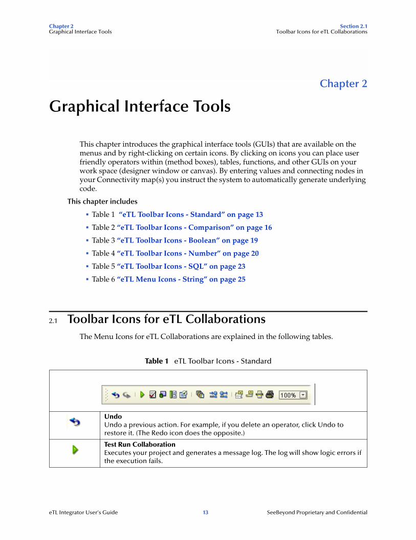
2.1 Toolbar Icons for eTL CollaborationsThe Menu Icons for eTL Collaborations are explained in the following tables.
Table 1 eTL Toolbar Icons - Standard
UndoUndo a previous action. For example, if you delete an operator, click Undo to restore it. (The Redo icon does the opposite.)
Test Run CollaborationExecutes your project and generates a message log. The log will show logic errors if the execution fails.
eTL Integrator User’s Guide 13 SeeBeyond Proprietary and Confidential
Chapter 2 Section 2.1Graphical Interface Tools Toolbar Icons for eTL Collaborations
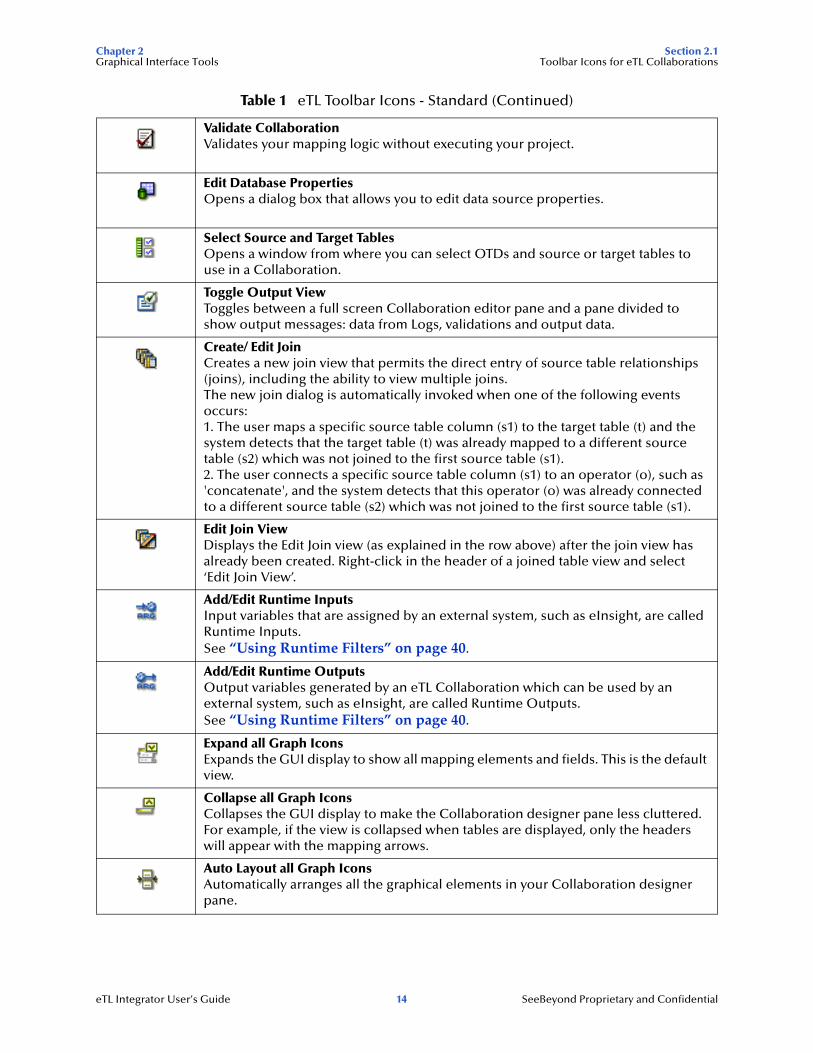
Validate CollaborationValidates your mapping logic without executing your project.
Edit Database PropertiesOpens a dialog box that allows you to edit data source properties.
Select Source and Target TablesOpens a window from where you can select OTDs and source or target tables to use in a Collaboration.
Toggle Output ViewToggles between a full screen Collaboration editor pane and a pane divided to show output messages: data from Logs, validations and output data.
Create/ Edit JoinCreates a new join view that permits the direct entry of source table relationships (joins), including the ability to view multiple joins. The new join dialog is automatically invoked when one of the following events occurs: 1. The user maps a specific source table column (s1) to the target table (t) and the system detects that the target table (t) was already mapped to a different source table (s2) which was not joined to the first source table (s1). 2. The user connects a specific source table column (s1) to an operator (o), such as 'concatenate', and the system detects that this operator (o) was already connected to a different source table (s2) which was not joined to the first source table (s1).
Edit Join ViewDisplays the Edit Join view (as explained in the row above) after the join view has already been created. Right-click in the header of a joined table view and select ‘Edit Join View’.
Add/Edit Runtime InputsInput variables that are assigned by an external system, such as eInsight, are called Runtime Inputs.See “Using Runtime Filters” on page 40.
Add/Edit Runtime OutputsOutput variables generated by an eTL Collaboration which can be used by an external system, such as eInsight, are called Runtime Outputs.See “Using Runtime Filters” on page 40.
Expand all Graph IconsExpands the GUI display to show all mapping elements and fields. This is the default view.
Collapse all Graph IconsCollapses the GUI display to make the Collaboration designer pane less cluttered. For example, if the view is collapsed when tables are displayed, only the headers will appear with the mapping arrows.
Auto Layout all Graph IconsAutomatically arranges all the graphical elements in your Collaboration designer pane.
Table 1 eTL Toolbar Icons - Standard (Continued)
eTL Integrator User’s Guide 14 SeeBeyond Proprietary and Confidential
Chapter 2 Section 2.2Graphical Interface Tools Using Operators
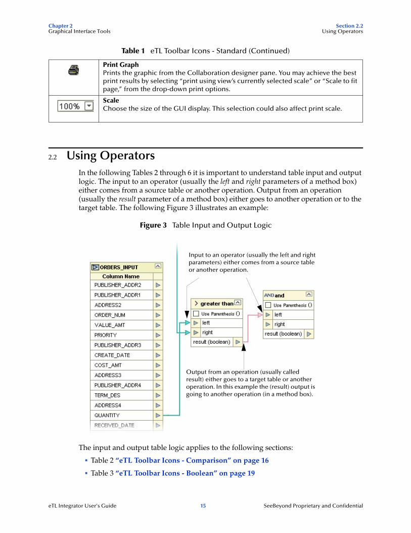
2.2 Using OperatorsIn the following Tables 2 through 6 it is important to understand table input and output logic. The input to an operator (usually the left and right parameters of a method box) either comes from a source table or another operation. Output from an operation (usually the result parameter of a method box) either goes to another operation or to the target table. The following Figure 3 illustrates an example:
Figure 3 Table Input and Output Logic
The input and output table logic applies to the following sections:
! Table 2 “eTL Toolbar Icons - Comparison” on page 16
! Table 3 “eTL Toolbar Icons - Boolean” on page 19
Print GraphPrints the graphic from the Collaboration designer pane. You may achieve the best print results by selecting “print using view’s currently selected scale” or “Scale to fit page,” from the drop-down print options.
ScaleChoose the size of the GUI display. This selection could also affect print scale.
Table 1 eTL Toolbar Icons - Standard (Continued)
Input to an operator (usually the left and right parameters) either comes from a source table or another operation.
Output from an operation (usually called result) either goes to a target table or another operation. In this example the (result) output is going to another operation (in a method box).
eTL Integrator User’s Guide 15 SeeBeyond Proprietary and Confidential

Chapter 2 Section 2.3Graphical Interface Tools Comparison Toolbar Icons—Operators
! Table 4 “eTL Toolbar Icons - Number” on page 20
! Table 5 “eTL Toolbar Icons - SQL” on page 23
! Table 6 “eTL Menu Icons - String” on page 25
2.3 Comparison Toolbar Icons—OperatorsThe Comparison operators are explained in the following Table 2. The operators are used within method boxes.
Table 2 eTL Toolbar Icons - Comparison
Method Box Description/Usage
not equalThe not equal operator returns true if the data column mapped to the left property is not equal to the right property; otherwise, returns false.
(Note: The items that are checked are the items
that show up in the toolbar.)
eTL Integrator User’s Guide 16 SeeBeyond Proprietary and Confidential
Chapter 2 Section 2.3Graphical Interface Tools Comparison Toolbar Icons—Operators
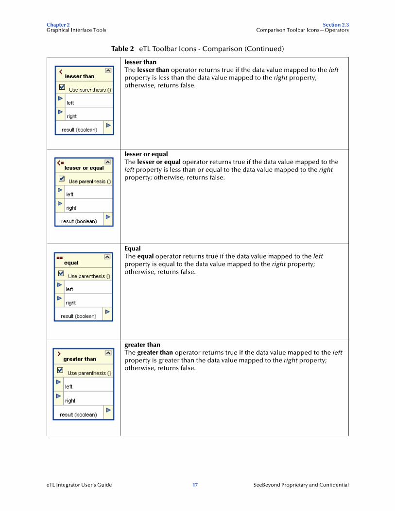
lesser thanThe lesser than operator returns true if the data value mapped to the left property is less than the data value mapped to the right property; otherwise, returns false.
lesser or equalThe lesser or equal operator returns true if the data value mapped to the left property is less than or equal to the data value mapped to the right property; otherwise, returns false.
EqualThe equal operator returns true if the data value mapped to the left property is equal to the data value mapped to the right property; otherwise, returns false.
greater thanThe greater than operator returns true if the data value mapped to the left property is greater than the data value mapped to the right property; otherwise, returns false.
Table 2 eTL Toolbar Icons - Comparison (Continued)
eTL Integrator User’s Guide 17 SeeBeyond Proprietary and Confidential
Chapter 2 Section 2.3Graphical Interface Tools Comparison Toolbar Icons—Operators
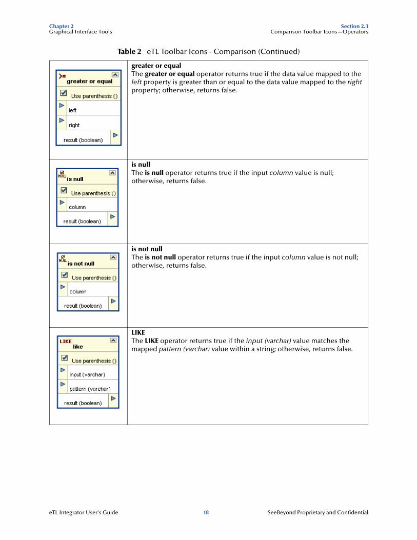
greater or equalThe greater or equal operator returns true if the data value mapped to the left property is greater than or equal to the data value mapped to the right property; otherwise, returns false.
is nullThe is null operator returns true if the input column value is null; otherwise, returns false.
is not nullThe is not null operator returns true if the input column value is not null; otherwise, returns false.
LIKEThe LIKE operator returns true if the input (varchar) value matches the mapped pattern (varchar) value within a string; otherwise, returns false.
Table 2 eTL Toolbar Icons - Comparison (Continued)
eTL Integrator User’s Guide 18 SeeBeyond Proprietary and Confidential
Chapter 2 Section 2.4Graphical Interface Tools Boolean Toolbar Icons—Operators
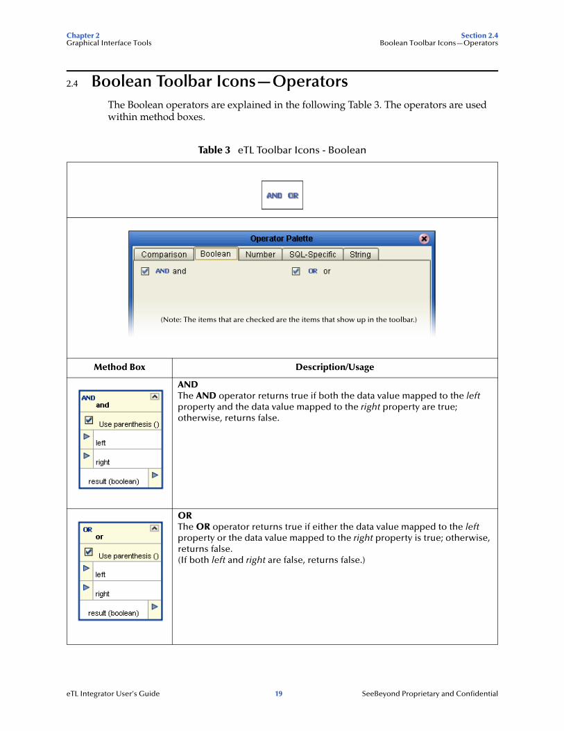
2.4 Boolean Toolbar Icons—OperatorsThe Boolean operators are explained in the following Table 3. The operators are used within method boxes.
Table 3 eTL Toolbar Icons - Boolean
Method Box Description/Usage
ANDThe AND operator returns true if both the data value mapped to the left property and the data value mapped to the right property are true; otherwise, returns false.
ORThe OR operator returns true if either the data value mapped to the left property or the data value mapped to the right property is true; otherwise, returns false.(If both left and right are false, returns false.)
(Note: The items that are checked are the items that show up in the toolbar.)
eTL Integrator User’s Guide 19 SeeBeyond Proprietary and Confidential
Chapter 2 Section 2.5Graphical Interface Tools Number Toolbar Icons—Operators
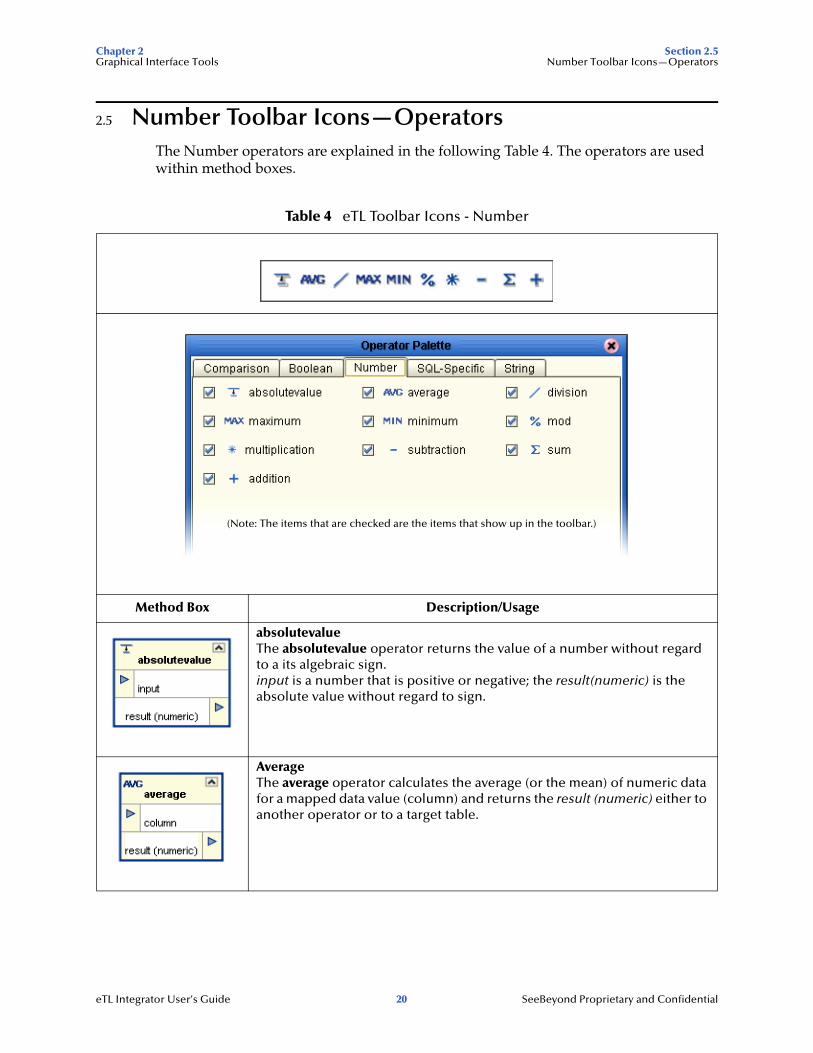
2.5 Number Toolbar Icons—OperatorsThe Number operators are explained in the following Table 4. The operators are used within method boxes.
Table 4 eTL Toolbar Icons - Number
Method Box Description/Usage
absolutevalueThe absolutevalue operator returns the value of a number without regard to a its algebraic sign.input is a number that is positive or negative; the result(numeric) is the absolute value without regard to sign.
AverageThe average operator calculates the average (or the mean) of numeric data for a mapped data value (column) and returns the result (numeric) either to another operator or to a target table.
(Note: The items that are checked are the items that show up in the toolbar.)
eTL Integrator User’s Guide 20 SeeBeyond Proprietary and Confidential
Chapter 2 Section 2.5Graphical Interface Tools Number Toolbar Icons—Operators
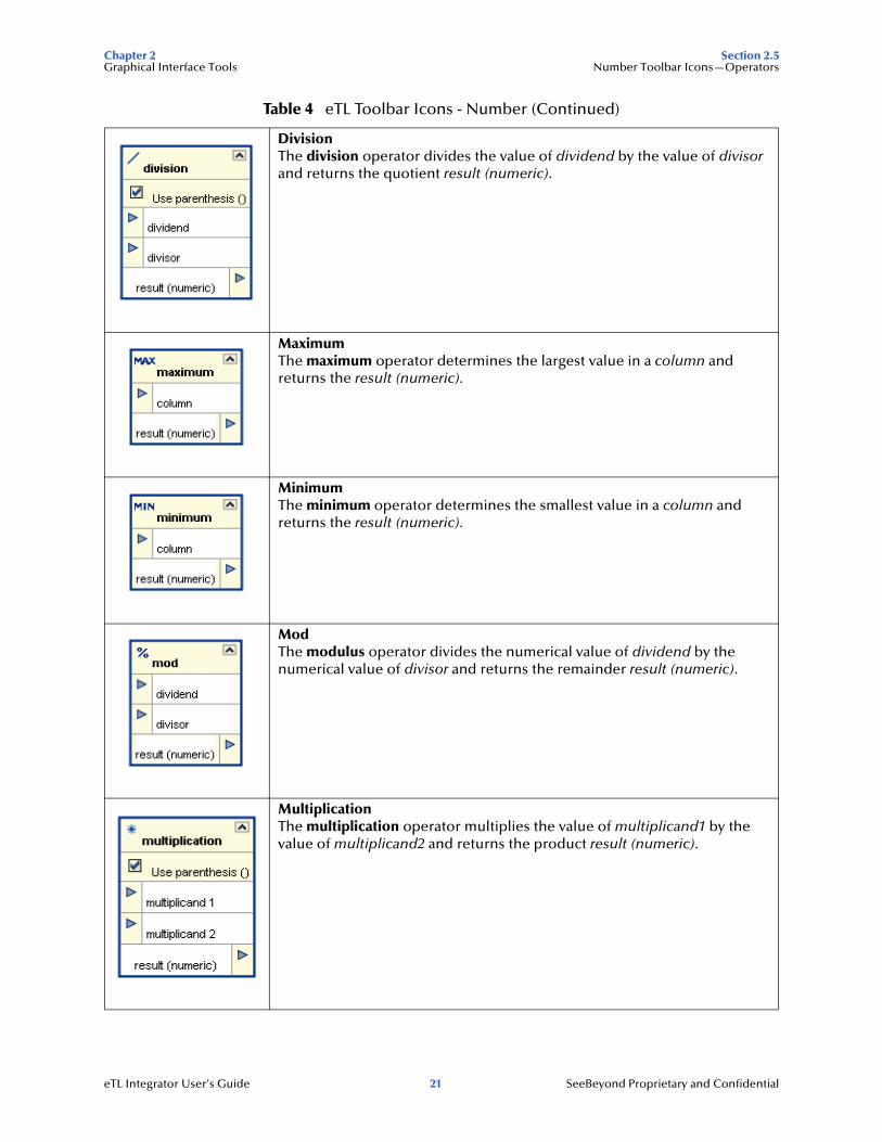
DivisionThe division operator divides the value of dividend by the value of divisor and returns the quotient result (numeric).
MaximumThe maximum operator determines the largest value in a column and returns the result (numeric).
MinimumThe minimum operator determines the smallest value in a column and returns the result (numeric).
ModThe modulus operator divides the numerical value of dividend by the numerical value of divisor and returns the remainder result (numeric).
MultiplicationThe multiplication operator multiplies the value of multiplicand1 by the value of multiplicand2 and returns the product result (numeric).
Table 4 eTL Toolbar Icons - Number (Continued)
eTL Integrator User’s Guide 21 SeeBeyond Proprietary and Confidential
Chapter 2 Section 2.5Graphical Interface Tools Number Toolbar Icons—Operators
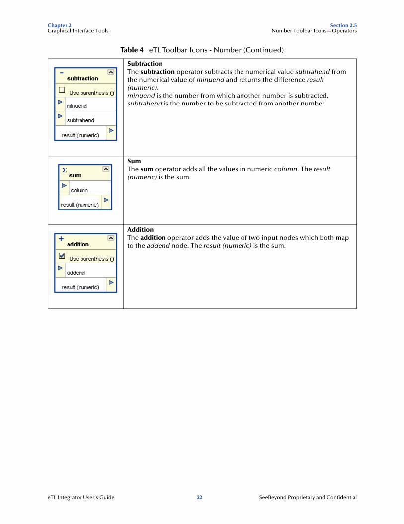
SubtractionThe subtraction operator subtracts the numerical value subtrahend from the numerical value of minuend and returns the difference result (numeric).minuend is the number from which another number is subtracted.subtrahend is the number to be subtracted from another number.
SumThe sum operator adds all the values in numeric column. The result (numeric) is the sum.
AdditionThe addition operator adds the value of two input nodes which both map to the addend node. The result (numeric) is the sum.
Table 4 eTL Toolbar Icons - Number (Continued)
eTL Integrator User’s Guide 22 SeeBeyond Proprietary and Confidential
Chapter 2 Section 2.6Graphical Interface Tools SQL Toolbar Icons—Operators
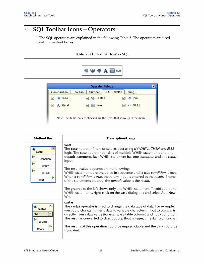
2.6 SQL Toolbar Icons—OperatorsThe SQL operators are explained in the following Table 5. The operators are used within method boxes.
Table 5 eTL Toolbar Icons - SQL
Method Box Description/Usage
caseThe case operator filters or selects data using If (WHEN), THEN and ELSE logic. The case operator consists of multiple WHEN statements and one default statement. Each WHEN statement has one condition and one return input.
The result value depends on the following:WHEN statements are evaluated in sequence until a true condition is met. When a condition is true, the return input is entered as the result. If none of the statements are true, the default value is the result.
The graphic to the left shows only one WHEN statement. To add additional WHEN statements, right-click on the case dialog box and select Add New When.
castasThe castas operator is used to change the data type of data. For example, you could change numeric data to variable characters. Input to column is directly from a data value (for example a table column) and not a condition. The result is converted to char, double, float, integer, timestamp or varchar.
The results of this operation could be unpredictable and the data could be truncated.
Note: The items that are checked are the items that show up in the menu.
eTL Integrator User’s Guide 23 SeeBeyond Proprietary and Confidential
Chapter 2 Section 2.6Graphical Interface Tools SQL Toolbar Icons—Operators
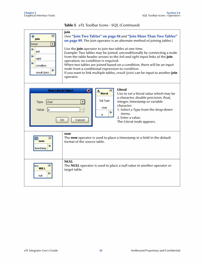
join(See “Join Two Tables” on page 84 and “Join More Than Two Tables” on page 89. The Join operator is an alternate method of joining tables.)
Use the join operator to join two tables at one time. Example: Two tables may be joined, unconditionally by connecting a node from the table header arrows to the left and right input links of the join operation; no condition is required.When two tables are joined based on a condition, there will be an input node from a conditional expression to condition.If you want to link multiple tables, result (join) can be input to another join operator.
nowThe now operator is used to place a timestamp in a field in the default format of the source table.
NULLThe NULL operator is used to place a null value in another operator or target table.
Table 5 eTL Toolbar Icons - SQL (Continued)
LiteralUse to set a literal value which may be a character, double precision, float, integer, timestamp or variable character. 1. Select a Type from the drop-down
menu.2. Enter a value.The Literal node appears.
eTL Integrator User’s Guide 24 SeeBeyond Proprietary and Confidential
Chapter 2 Section 2.7Graphical Interface Tools String Toolbar Icons—Operators
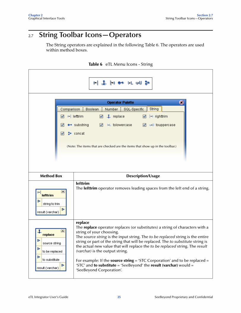
2.7 String Toolbar Icons—OperatorsThe String operators are explained in the following Table 6. The operators are used within method boxes.
Table 6 eTL Menu Icons - String
Method Box Description/Usage
lefttrimThe lefttrim operator removes leading spaces from the left end of a string.
replaceThe replace operator replaces (or substitutes) a string of characters with a string of your choosing.The source string is the input string. The to be replaced string is the entire string or part of the string that will be replaced. The to substitute string is the actual new value that will replace the to be replaced string. The result (varchar) is the output string.
For example: If the source string = ‘STC Corporation’ and to be replaced = ‘STC’ and to substitute = ‘SeeBeyond’ the result (varchar) would = ‘SeeBeyond Corporation’.
(Note: The items that are checked are the items that show up in the toolbar.)
eTL Integrator User’s Guide 25 SeeBeyond Proprietary and Confidential
Chapter 2 Section 2.7Graphical Interface Tools String Toolbar Icons—Operators
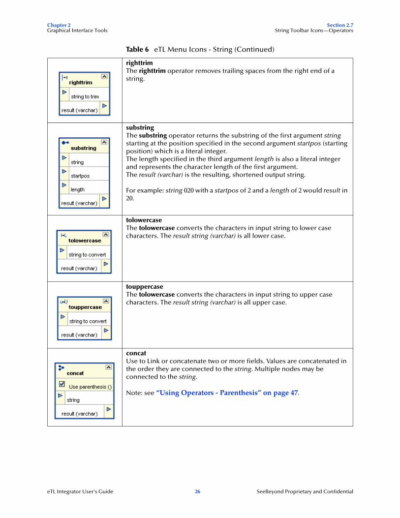
righttrimThe righttrim operator removes trailing spaces from the right end of a string.
substringThe substring operator returns the substring of the first argument string starting at the position specified in the second argument startpos (starting position) which is a literal integer. The length specified in the third argument length is also a literal integer and represents the character length of the first argument. The result (varchar) is the resulting, shortened output string.
For example: string 020 with a startpos of 2 and a length of 2 would result in 20.
tolowercaseThe tolowercase converts the characters in input string to lower case characters. The result string (varchar) is all lower case.
touppercaseThe tolowercase converts the characters in input string to upper case characters. The result string (varchar) is all upper case.
concatUse to Link or concatenate two or more fields. Values are concatenated in the order they are connected to the string. Multiple nodes may be connected to the string.
Note: see “Using Operators - Parenthesis” on page 47.
Table 6 eTL Menu Icons - String (Continued)
eTL Integrator User’s Guide 26 SeeBeyond Proprietary and Confidential
Chapter 3 Section 3.1Interface to the eGate Enterprise Designer Enterprise Designer Components
Chapter 3
Interface to the eGate Enterprise Designer
The Enterprise Designer is the graphical user interface (GUI) used to design and implement ICAN 5.0 projects. This chapter overviews the features and interface of the Enterprise Designer window.
This chapter includes
! “Enterprise Designer Components” on page 27
! “Menu Bar” on page 28
! “Enterprise Explorer” on page 29
! “Project Editor” on page 29
3.1 Enterprise Designer ComponentsThe Enterprise Designer is used to create and configure the components of an ICAN Project. Each component of this interface is identified in Figure 4.
eTL Integrator User’s Guide 27 SeeBeyond Proprietary and Confidential
Chapter 3 Section 3.2Interface to the eGate Enterprise Designer Menu Bar
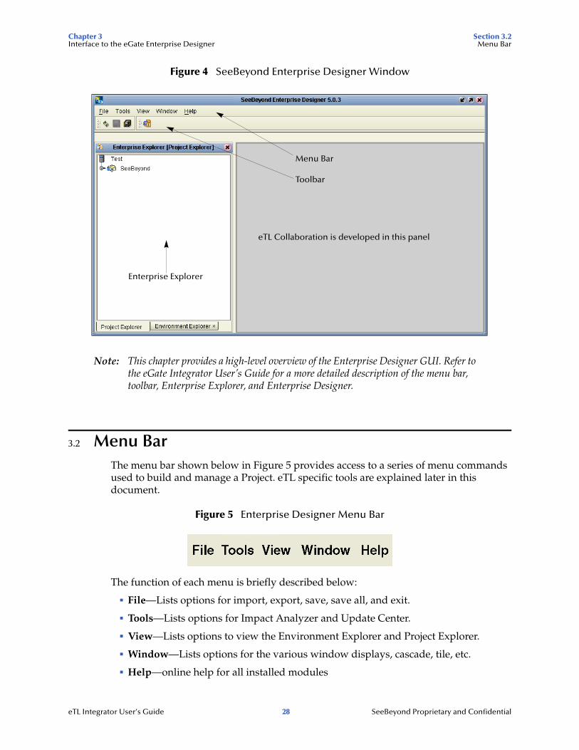
Figure 4 SeeBeyond Enterprise Designer Window
Note: This chapter provides a high-level overview of the Enterprise Designer GUI. Refer to the eGate Integrator User’s Guide for a more detailed description of the menu bar, toolbar, Enterprise Explorer, and Enterprise Designer.
3.2 Menu BarThe menu bar shown below in Figure 5 provides access to a series of menu commands used to build and manage a Project. eTL specific tools are explained later in this document.
Figure 5 Enterprise Designer Menu Bar
The function of each menu is briefly described below:
! File—Lists options for import, export, save, save all, and exit.
! Tools—Lists options for Impact Analyzer and Update Center.
! View—Lists options to view the Environment Explorer and Project Explorer.
! Window—Lists options for the various window displays, cascade, tile, etc.
! Help—online help for all installed modules
Enterprise Explorer
Menu Bar
Toolbar
eTL Collaboration is developed in this panel
eTL Integrator User’s Guide 28 SeeBeyond Proprietary and Confidential
Chapter 3 Section 3.3Interface to the eGate Enterprise Designer Enterprise Explorer
3.3 Enterprise ExplorerThe Enterprise Explorer organizes all of the components of a Project into a series of folders and contains the following two tabs:
! Project Explorer—Logical configurations designed to help solve a business problem. This branch includes all the components of an Enterprise Designer Project, including Collaborations, Connectivity Maps, Services, Object Type Definitions (OTD), and Deployment Profiles.
! Environment Explorer—Collections of logical hosts and external systems capable of hosting eGate components and information about external systems, which may be involved with an eGate configuration.
3.4 Project EditorThe Project Editor contains the “nuts-and-bolts” of a Project. This part of the Enterprise Designer is empty when you start a new Project. However, as you work through the tutorial, the Project Editor quickly fills with components and graphical structures representing the various stages of the Project. The types of windows in the Project Editor area include:
! Connectivity Map—Contains business logic components, such as Services, Topics, queues, and eWays, that you include in the structure of a Project
! OTD Editor—Edits and tests the OTDs (Object Type Definitions)
! eTL Editor—Creates eTL Collaborations
! Deployment Profile Editor—Edits the deployment profile
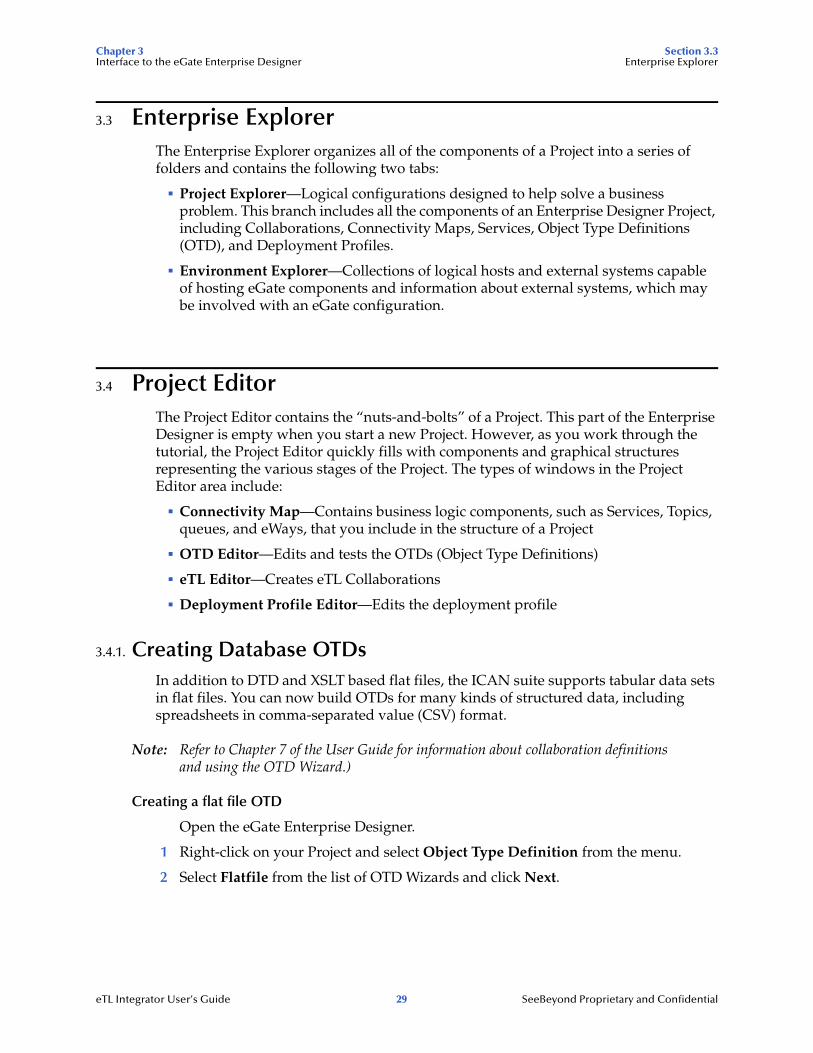
3.4.1. Creating Database OTDsIn addition to DTD and XSLT based flat files, the ICAN suite supports tabular data sets in flat files. You can now build OTDs for many kinds of structured data, including spreadsheets in comma-separated value (CSV) format.
Note: Refer to Chapter 7 of the User Guide for information about collaboration definitions and using the OTD Wizard.)
Creating a flat file OTD
Open the eGate Enterprise Designer.
1 Right-click on your Project and select Object Type Definition from the menu.
2 Select Flatfile from the list of OTD Wizards and click Next.
eTL Integrator User’s Guide 29 SeeBeyond Proprietary and Confidential
Chapter 3 Section 3.4Interface to the eGate Enterprise Designer Project Editor
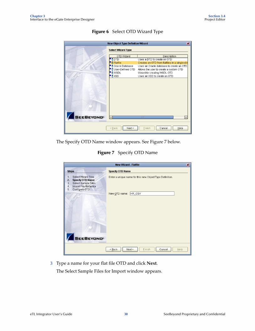
Figure 6 Select OTD Wizard Type
The Specify OTD Name window appears. See Figure 7 below.
Figure 7 Specify OTD Name
3 Type a name for your flat file OTD and click Next.
The Select Sample Files for Import window appears.
eTL Integrator User’s Guide 30 SeeBeyond Proprietary and Confidential
Chapter 3 Section 3.4Interface to the eGate Enterprise Designer Project Editor
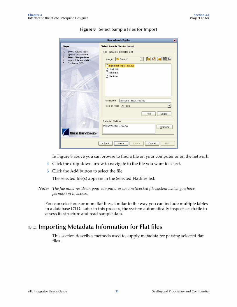
Figure 8 Select Sample Files for Import
In Figure 8 above you can browse to find a file on your computer or on the network.
4 Click the drop-down arrow to navigate to the file you want to select.
5 Click the Add button to select the file.
The selected file(s) appears in the Selected Flatfiles list.
Note: The file must reside on your computer or on a networked file system which you have permission to access.
You can select one or more flat files, similar to the way you can include multiple tables in a database OTD. Later in this process, the system automatically inspects each file to assess its structure and read sample data.
3.4.2. Importing Metadata Information for Flat filesThis section describes methods used to supply metadata for parsing selected flat files.
eTL Integrator User’s Guide 31 SeeBeyond Proprietary and Confidential

Chapter 3 Section 3.4Interface to the eGate Enterprise Designer Project Editor
Figure 9 Encoding Scheme and File Format
1 Enter a Table name and select an encoding scheme. The default encoding is ASCII.
2 Select a File format, Delimited or Fixed-width.
For the delimited format, there are five criteria and delimiters used to instruct the system how to parse your selected flat file:
" Default SQL Type
" Record Delimiter
" Field Delimiter
" Text Qualifier
" First line contains field names?
In our sample we are configuring the delimited format, Figure 11. The following figure shows an example of fixed width format properties:
eTL Integrator User’s Guide 32 SeeBeyond Proprietary and Confidential

Chapter 3 Section 3.4Interface to the eGate Enterprise Designer Project Editor
Figure 10 Fixed Width Parse Properties, Record length
eTL Integrator User’s Guide 33 SeeBeyond Proprietary and Confidential
Chapter 3 Section 3.4Interface to the eGate Enterprise Designer Project Editor
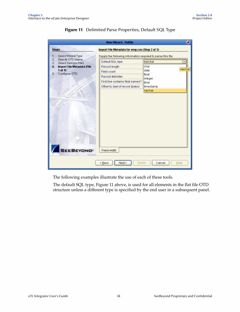
Figure 11 Delimited Parse Properties, Default SQL Type
The following examples illustrate the use of each of these tools.
The default SQL type, Figure 11 above, is used for all elements in the flat file OTD structure unless a different type is specified by the end user in a subsequent panel.
eTL Integrator User’s Guide 34 SeeBeyond Proprietary and Confidential

Chapter 3 Section 3.4Interface to the eGate Enterprise Designer Project Editor
Figure 12 Specify Record Delimiter
The Record Delimiter, Figure 12 above, allows you to specify how the various records in the flat file are physically separated from each other.
Figure 13 Specify Field Delimiter
The Field Delimiter, Figure 13 above, specifies how the various elements (fields) in the flat file records are physically separated from each other. The following field delimiters are supported: comma, tab, and pipe (|).
eTL Integrator User’s Guide 35 SeeBeyond Proprietary and Confidential

Chapter 3 Section 3.4Interface to the eGate Enterprise Designer Project Editor
Figure 14 Specify Text Qualifier
The Text Qualifier, Figure 14 above, explicitly specifies how eTL Integrator detects text fields. You can select double quote (“), single quote (‘), or none.
Figure 15 First Line Contains
The “First line contains...” offers a True or False selection. See Figure 15 above. You can specify whether the selected includes the names of its fields in its header row.
eTL Integrator User’s Guide 36 SeeBeyond Proprietary and Confidential
Chapter 3 Section 3.4Interface to the eGate Enterprise Designer Project Editor
! True - the names specified in the header row are used as element names of the new OTD.
! False - the eTL Integrator dynamically assigns initial names to the new OTD elements, which can be changed in the next panel.
Suggested OTD Record Structure
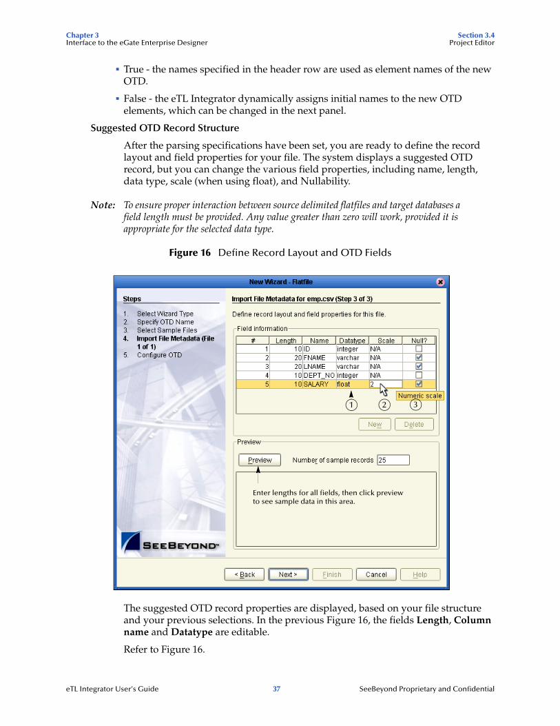
After the parsing specifications have been set, you are ready to define the record layout and field properties for your file. The system displays a suggested OTD record, but you can change the various field properties, including name, length, data type, scale (when using float), and Nullability.
Note: To ensure proper interaction between source delimited flatfiles and target databases a field length must be provided. Any value greater than zero will work, provided it is appropriate for the selected data type.
Figure 16 Define Record Layout and OTD Fields
The suggested OTD record properties are displayed, based on your file structure and your previous selections. In the previous Figure 16, the fields Length, Column name and Datatype are editable.
Refer to Figure 16.
21 3
Enter lengths for all fields, then click previewto see sample data in this area.
eTL Integrator User’s Guide 37 SeeBeyond Proprietary and Confidential
Chapter 3 Section 3.4Interface to the eGate Enterprise Designer Project Editor
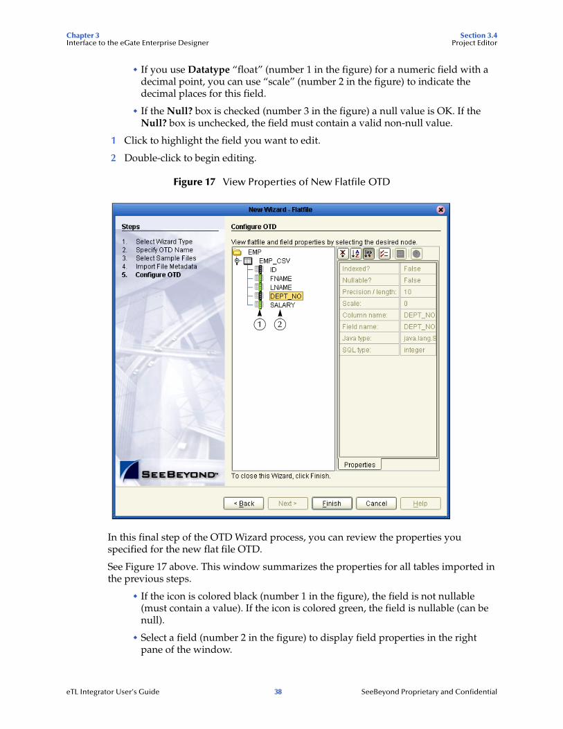
" If you use Datatype “float” (number 1 in the figure) for a numeric field with a decimal point, you can use “scale” (number 2 in the figure) to indicate the decimal places for this field.
" If the Null? box is checked (number 3 in the figure) a null value is OK. If the Null? box is unchecked, the field must contain a valid non-null value.
1 Click to highlight the field you want to edit.
2 Double-click to begin editing.
Figure 17 View Properties of New Flatfile OTD
In this final step of the OTD Wizard process, you can review the properties you specified for the new flat file OTD.
See Figure 17 above. This window summarizes the properties for all tables imported in the previous steps.
" If the icon is colored black (number 1 in the figure), the field is not nullable (must contain a value). If the icon is colored green, the field is nullable (can be null).
" Select a field (number 2 in the figure) to display field properties in the right pane of the window.
1 2
eTL Integrator User’s Guide 38 SeeBeyond Proprietary and Confidential
Chapter 3 Section 3.4Interface to the eGate Enterprise Designer Project Editor
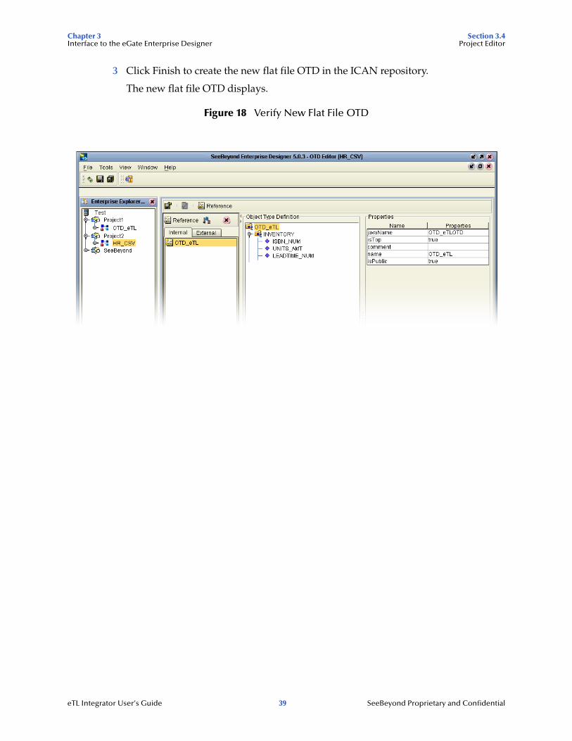
3 Click Finish to create the new flat file OTD in the ICAN repository.
The new flat file OTD displays.
Figure 18 Verify New Flat File OTD
eTL Integrator User’s Guide 39 SeeBeyond Proprietary and Confidential
Chapter 4 Section 4.1Extraction Filters and Implementation Conditions Using Runtime Filters
Chapter 4
Extraction Filters and Implementation Conditions
4.1 Using Runtime FiltersThe eTL tools explained in this section offer various ways to extract and filter data, either input or output. Runtime arguments are only used with eInsight.
4.1.1. Configuring Inserts and Updates
Users can configure the runtime load process to determine whether to insert or update based on a condition. Conditions can use data in a source table as well as data from within a runtime input argument.
1 Right-click on the target table.
2 Click on Properties.
3 Click inside the Insert/Update field.
4 Click the drop-down arrow.
eTL Integrator User’s Guide 40 SeeBeyond Proprietary and Confidential

Chapter 4 Section 4.1Extraction Filters and Implementation Conditions Using Runtime Filters
Figure 19 Insert/Update Properties
" Select Insert (default) to always append new rows.
" Select Insert/Update to update an existing row or append a new row, depending on the evaluation of a condition.
" Select Update to update only existing rows.
" Select Delete to delete rows.
4.1.2. Input and Output Runtime ArgumentsUse “runtime argument” operators to add input and/or output variables (business process attributes) to the collaboration.
Set Runtime Input Argument
You can use runtime arguments to select and filter data. In the following example enter the variable ‘AP’ to select the PUBLISHER_CD (Publisher code) Adamson Publishing.
1 Click the Add/Edit Runtime Inputs button.
The Add Input Runtime Arguments window appears.
eTL Integrator User’s Guide 41 SeeBeyond Proprietary and Confidential

Chapter 4 Section 4.1Extraction Filters and Implementation Conditions Using Runtime Filters
Figure 20 Add Input Runtime Arguments
2 Name the argument Publisher_Code.
3 Enter AP as the default value.
4 Select Varchar.
5 Type 3 in the Precision field.
6 Click OK.
Refer to the following Figure 21.
eTL Integrator User’s Guide 42 SeeBeyond Proprietary and Confidential

Chapter 4 Section 4.1Extraction Filters and Implementation Conditions Using Runtime Filters
Figure 21 Map Runtime Input Argument
7 The runtime argument variable which is ‘AP’ is compared to the Publisher code (PUBLISHER_CD). When the condition is true the next operator is evaluated. (In this scenario the next condition is ‘and’ (followed by ‘equal’) to verify that INVENTORY.ISBN_NUM = ORDERS_INPUT.ITEM_CD.)
The runtime argument (filter) shown Figure 20 and Figure 21 would be used to capture only records for ‘AP’ (Adamson Publishing).
Set Runtime Output Argument
Runtime output arguments are used for counts, status and timestamps.
4.1.3. Conditional ExtractionsThe eTL Condition Builder is another powerful tool for filtering and selecting data for extraction.
Source Table Extractions
Setting a condition with Condition Builder to filter a source table is called an “extraction condition.” Setting a condition with Condition Builder to filter a target table is called a “condition.” The following steps demonstrate a source table extraction condition:
Right click the source table to display the pop up dialog box. To configure an extraction condition, start with Properties.
Select orders with an input value that is greater than $1000
If you wanted to select input orders with a value greater than $1000, you could create a conditional extraction as shown in the following steps.
1 Right click the graphical representation of the ORDERS_INPUT table.
eTL Integrator User’s Guide 43 SeeBeyond Proprietary and Confidential
Chapter 4 Section 4.1Extraction Filters and Implementation Conditions Using Runtime Filters
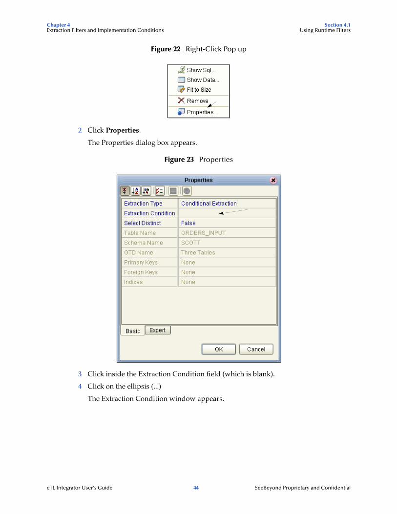
Figure 22 Right-Click Pop up
2 Click Properties.
The Properties dialog box appears.
Figure 23 Properties
3 Click inside the Extraction Condition field (which is blank).
4 Click on the ellipsis (...)
The Extraction Condition window appears.
eTL Integrator User’s Guide 44 SeeBeyond Proprietary and Confidential
Chapter 4 Section 4.1Extraction Filters and Implementation Conditions Using Runtime Filters
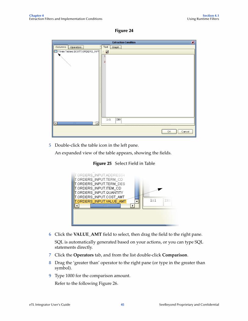
Figure 24
5 Double-click the table icon in the left pane.
An expanded view of the table appears, showing the fields.
Figure 25 Select Field in Table
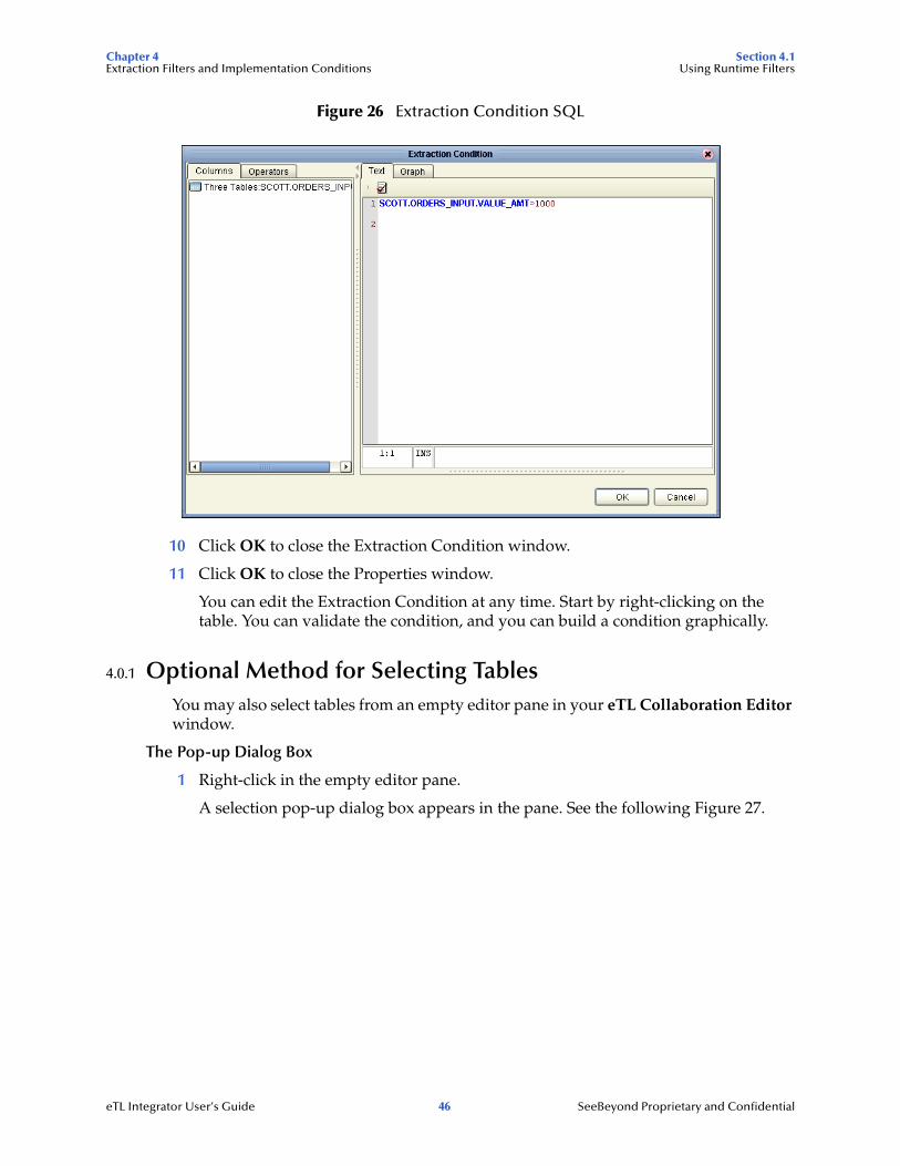
6 Click the VALUE_AMT field to select, then drag the field to the right pane.
SQL is automatically generated based on your actions, or you can type SQL statements directly.
7 Click the Operators tab, and from the list double-click Comparison.
8 Drag the ‘greater than’ operator to the right pane (or type in the greater than symbol).
9 Type 1000 for the comparison amount.
Refer to the following Figure 26.
eTL Integrator User’s Guide 45 SeeBeyond Proprietary and Confidential
Chapter 4 Section 4.1Extraction Filters and Implementation Conditions Using Runtime Filters
Figure 26 Extraction Condition SQL
10 Click OK to close the Extraction Condition window.
11 Click OK to close the Properties window.
You can edit the Extraction Condition at any time. Start by right-clicking on the table. You can validate the condition, and you can build a condition graphically.
4.0.1 Optional Method for Selecting TablesYou may also select tables from an empty editor pane in your eTL Collaboration Editor window.
The Pop-up Dialog Box
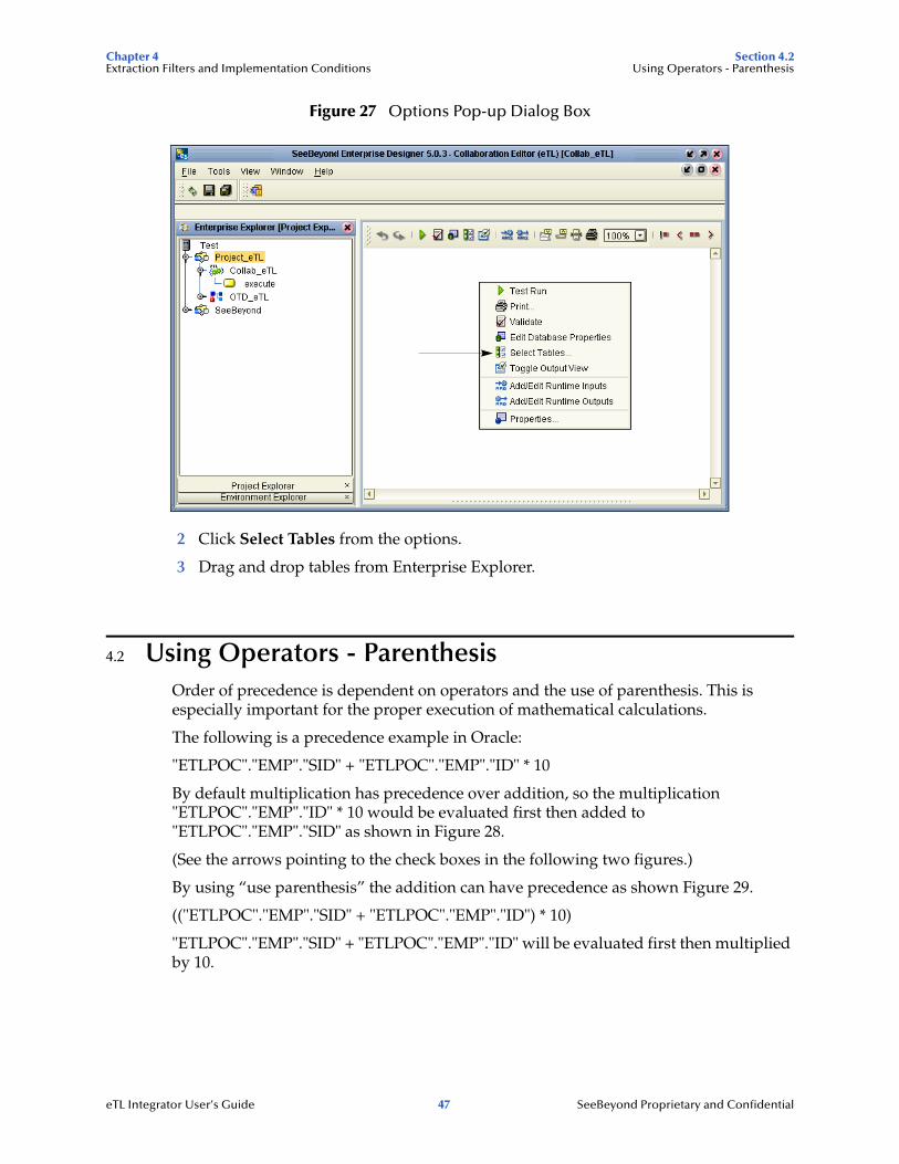
1 Right-click in the empty editor pane.
A selection pop-up dialog box appears in the pane. See the following Figure 27.
eTL Integrator User’s Guide 46 SeeBeyond Proprietary and Confidential
Chapter 4 Section 4.2Extraction Filters and Implementation Conditions Using Operators - Parenthesis
Figure 27 Options Pop-up Dialog Box
2 Click Select Tables from the options.
3 Drag and drop tables from Enterprise Explorer.
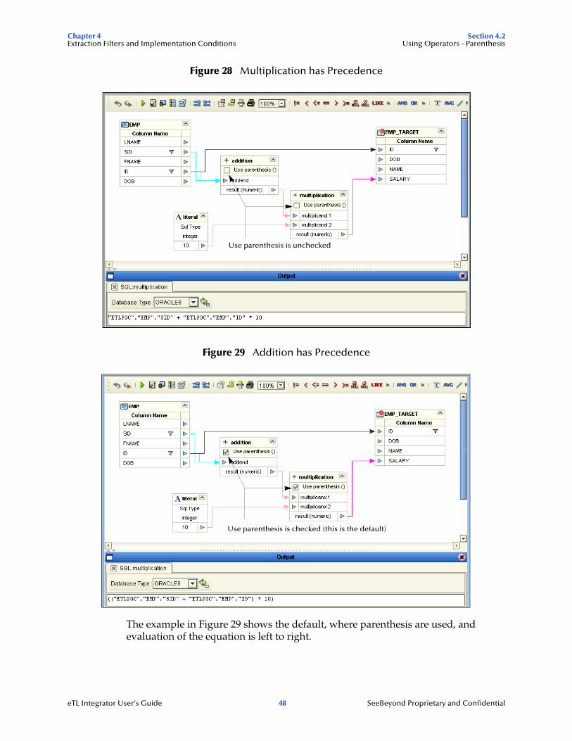
4.2 Using Operators - ParenthesisOrder of precedence is dependent on operators and the use of parenthesis. This is especially important for the proper execution of mathematical calculations.
The following is a precedence example in Oracle:
"ETLPOC"."EMP"."SID" + "ETLPOC"."EMP"."ID" * 10
By default multiplication has precedence over addition, so the multiplication "ETLPOC"."EMP"."ID" * 10 would be evaluated first then added to "ETLPOC"."EMP"."SID" as shown in Figure 28.
(See the arrows pointing to the check boxes in the following two figures.)
By using “use parenthesis” the addition can have precedence as shown Figure 29.
(("ETLPOC"."EMP"."SID" + "ETLPOC"."EMP"."ID") * 10)
"ETLPOC"."EMP"."SID" + "ETLPOC"."EMP"."ID" will be evaluated first then multiplied by 10.
eTL Integrator User’s Guide 47 SeeBeyond Proprietary and Confidential
Chapter 4 Section 4.2Extraction Filters and Implementation Conditions Using Operators - Parenthesis
Figure 28 Multiplication has Precedence
Figure 29 Addition has Precedence
The example in Figure 29 shows the default, where parenthesis are used, and evaluation of the equation is left to right.
Use parenthesis is unchecked
Use parenthesis is checked (this is the default)
eTL Integrator User’s Guide 48 SeeBeyond Proprietary and Confidential

Chapter 5 Section 5.1Creating a Sample Project Using Flatfiles Sample Scenario Data
Chapter 5
Creating a Sample Project Using Flatfiles
The following scenario guides you through creation and deployment of a project. This scenario includes the following sections:
! “Sample Scenario Data” on page 49
! “Mapping Tables” on page 58
! “Connectivity Map” on page 64
! “Deployment Profile for eTL” on page 66
! “Run the Bootstrap and Management Agent” on page 68
! “Verify the Output Data” on page 69
Note: The CSV (Comma Separated Values) files used in this scenario are flatfiles. These flatfiles, when used in the context of eTL in this scenario, are referred to as tables.
5.1 Sample Scenario DataTo do this project you must have (or create from the tables below) three sample CSV files: CSV_ORDERS_INPUT, CSV_INVENTORY_INPUT and CSV_EXCEPTIONS_OUTPUT.
The following tables show the data needed for this scenario:
Table 7 Orders Input Table (CSV)
Order_num Priority Reveived_date Bookseller_name ISBN_num Order_qty10001 5 9/26/2004 Adamson Pub 0-4545-2110-2 25010001 3 9/26/2004 Adamson Pub 0-4545-2210-1 40010002 7 4/4/2004 Firestone Livres 0-4545-2310-7 12010002 5 4/4/2004 Firestone Livres 0-4545-3221-2 2010003 4 5/11/2004 Hardcount Pub 0-4545-3366-5 21010003 9 5/11/2004 Hardcount Pub 0-4545-3413-2 2010004 2 6/10/2004 Moonves Books 0-4545-3421-6 40010004 5 6/10/2004 Moonves Books 0-4545-3535-3 10010004 7 6/10/2004 Moonves Books 0-4545-4369-1 2010005 8 10/17/2004 Ural Russian Lit 0-4545-5413-8 70
eTL Integrator User’s Guide 49 SeeBeyond Proprietary and Confidential
Chapter 5 Section 5.1Creating a Sample Project Using Flatfiles Sample Scenario Data
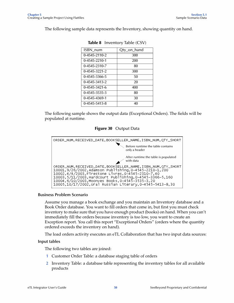
The following sample data represents the Inventory, showing quantity on hand.
The following sample shows the output data (Exceptional Orders). The fields will be populated at runtime.
Figure 30 Output Data
Business Problem Scenario
Assume you manage a book exchange and you maintain an Inventory database and a Book Order database. You want to fill orders that come in, but first you must check inventory to make sure that you have enough product (books) on hand. When you can’t immediately fill the orders because inventory is too low, you want to create an Exception report. You call this report “Exceptional Orders” (orders where the quantity ordered exceeds the inventory on hand).
The load orders activity executes an eTL Collaboration that has two input data sources:
Input tables
The following two tables are joined:
1 Customer Order Table: a database staging table of orders
2 Inventory Table: a database table representing the inventory tables for all available products
Table 8 Inventory Table (CSV)
ISBN_num Qty_on_hand0-4545-2110-2 3000-4545-2210-1 2000-4545-2310-7 800-4545-3221-2 3000-4545-3366-5 500-4545-3413-2 200-4545-3421-6 4000-4545-3535-3 800-4545-4369-1 300-4545-5413-8 40
Before runtime the table containsonly a header
After runtime the table is populatedwith data
eTL Integrator User’s Guide 50 SeeBeyond Proprietary and Confidential

Chapter 5 Section 5.1Creating a Sample Project Using Flatfiles Sample Scenario Data
Target table
The target, Exceptional table, is the extracted compilation of orders that couldn’t be filled because of insufficient inventory.
! Exceptional table: a database table with the exception orders. (You don’t have the inventory to fill these orders.)
5.1.1. Create and Name a ProjectStart a New Project
1 In the Enterprise Explorer pane of the Enterprise Designer, right-click the
Repository name (computer icon ), and then click New Project.
Figure 31 Create a Project
2 Name your project.
The Project1 (default name) appears in the Explorer pane on the left side of the window.
5.1.2. Create a New Object Type DefinitionDefine OTDs
Create definitions for database tables.
1 Right-click your project name.
2 Click New and Object Type Definition.
eTL Integrator User’s Guide 51 SeeBeyond Proprietary and Confidential
Chapter 5 Section 5.1Creating a Sample Project Using Flatfiles Sample Scenario Data
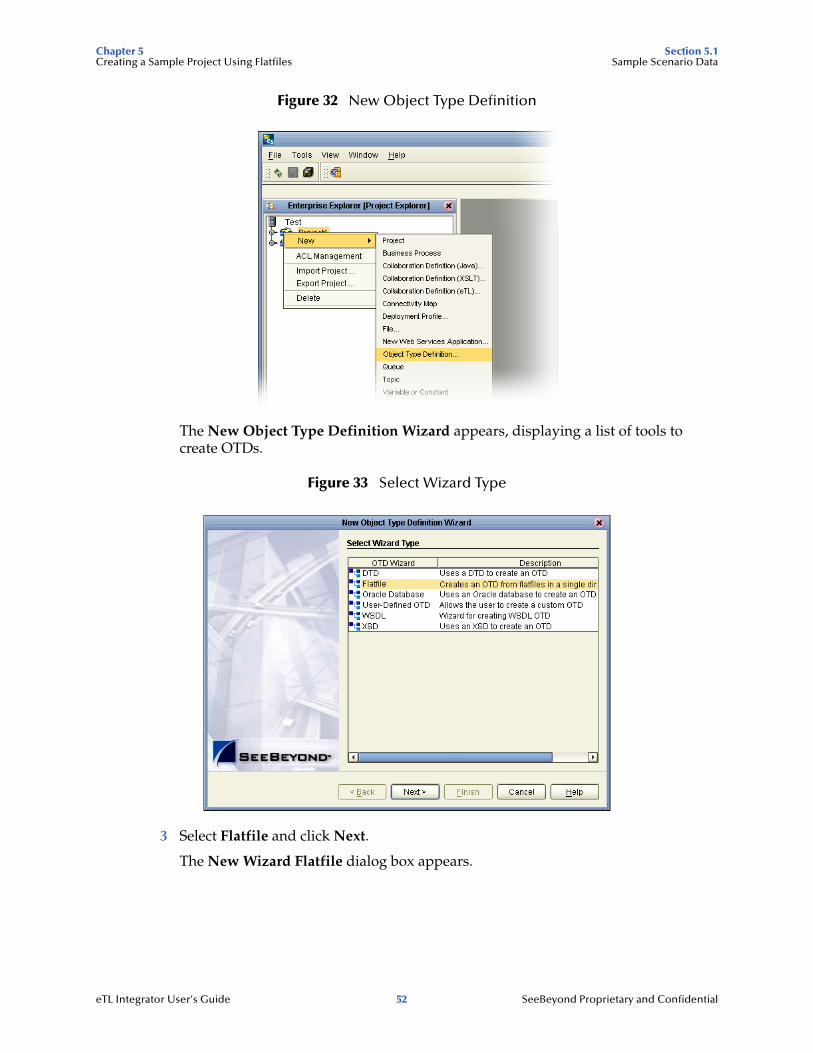
Figure 32 New Object Type Definition
The New Object Type Definition Wizard appears, displaying a list of tools to create OTDs.
Figure 33 Select Wizard Type
3 Select Flatfile and click Next.
The New Wizard Flatfile dialog box appears.
eTL Integrator User’s Guide 52 SeeBeyond Proprietary and Confidential
Chapter 5 Section 5.1Creating a Sample Project Using Flatfiles Sample Scenario Data
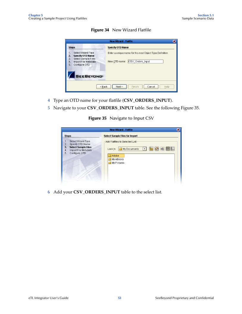
Figure 34 New Wizard Flatfile
4 Type an OTD name for your flatfile (CSV_ORDERS_INPUT).
5 Navigate to your CSV_ORDERS_INPUT table. See the following Figure 35.
Figure 35 Navigate to Input CSV
6 Add your CSV_ORDERS_INPUT table to the select list.
eTL Integrator User’s Guide 53 SeeBeyond Proprietary and Confidential
Chapter 5 Section 5.1Creating a Sample Project Using Flatfiles Sample Scenario Data
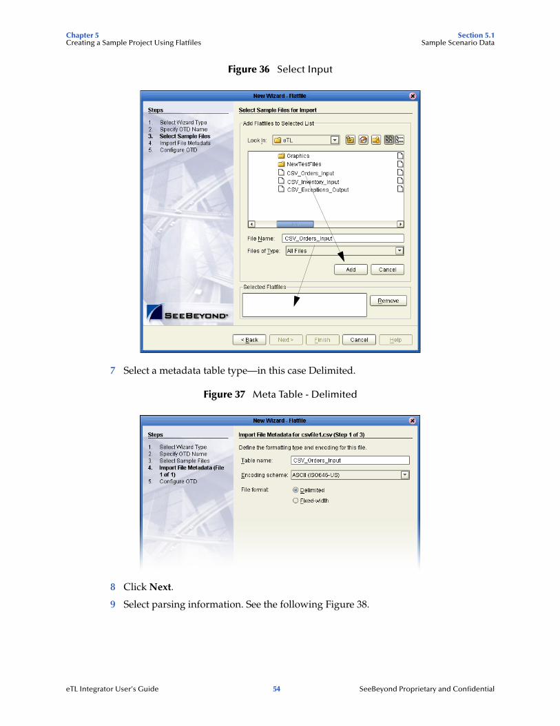
Figure 36 Select Input
7 Select a metadata table type—in this case Delimited.
Figure 37 Meta Table - Delimited
8 Click Next.
9 Select parsing information. See the following Figure 38.
eTL Integrator User’s Guide 54 SeeBeyond Proprietary and Confidential
Chapter 5 Section 5.1Creating a Sample Project Using Flatfiles Sample Scenario Data
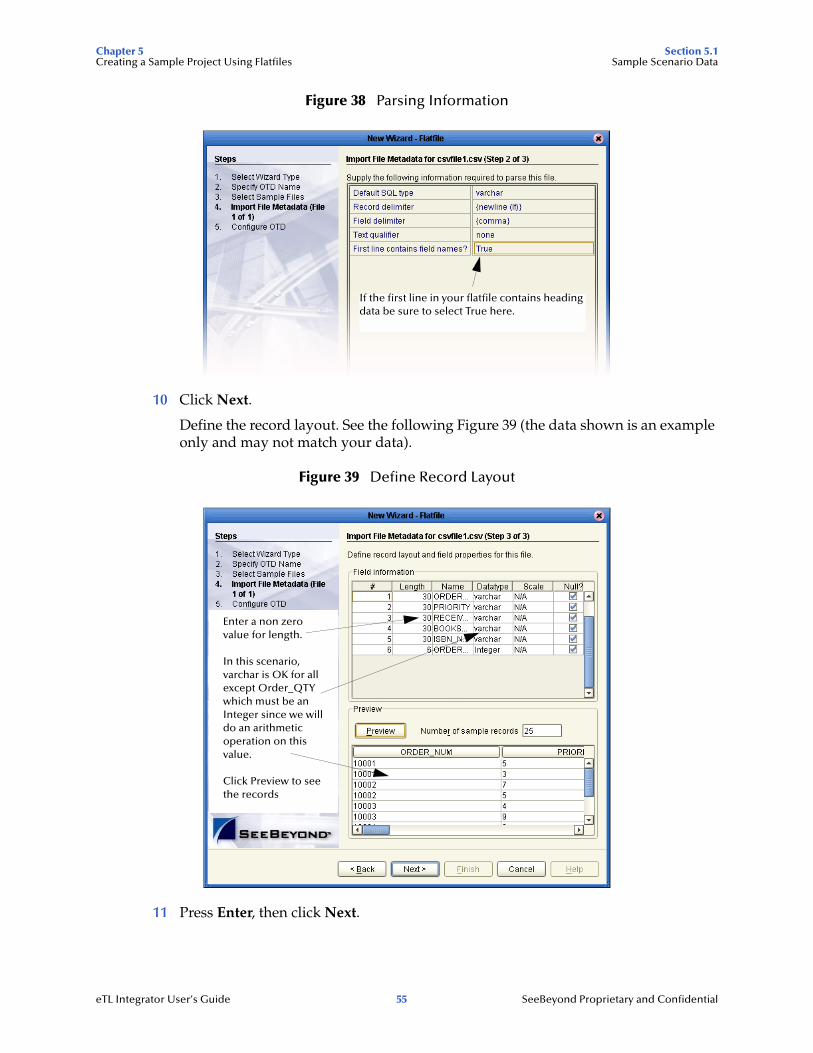
Figure 38 Parsing Information
10 Click Next.
Define the record layout. See the following Figure 39 (the data shown is an example only and may not match your data).
Figure 39 Define Record Layout
11 Press Enter, then click Next.
If the first line in your flatfile contains heading data be sure to select True here.
Enter a non zero value for length.
In this scenario, varchar is OK for all except Order_QTY which must be an Integer since we will do an arithmetic operation on this value.
Click Preview to see the records
eTL Integrator User’s Guide 55 SeeBeyond Proprietary and Confidential
Chapter 5 Section 5.1Creating a Sample Project Using Flatfiles Sample Scenario Data
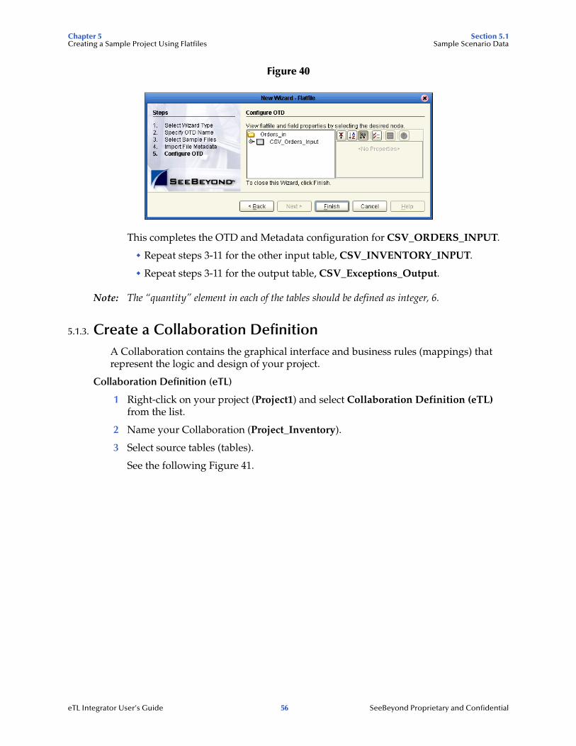
Figure 40
This completes the OTD and Metadata configuration for CSV_ORDERS_INPUT.
" Repeat steps 3-11 for the other input table, CSV_INVENTORY_INPUT.
" Repeat steps 3-11 for the output table, CSV_Exceptions_Output.
Note: The “quantity” element in each of the tables should be defined as integer, 6.
5.1.3. Create a Collaboration DefinitionA Collaboration contains the graphical interface and business rules (mappings) that represent the logic and design of your project.
Collaboration Definition (eTL)
1 Right-click on your project (Project1) and select Collaboration Definition (eTL) from the list.
2 Name your Collaboration (Project_Inventory).
3 Select source tables (tables).
See the following Figure 41.
eTL Integrator User’s Guide 56 SeeBeyond Proprietary and Confidential
Chapter 5 Section 5.1Creating a Sample Project Using Flatfiles Sample Scenario Data
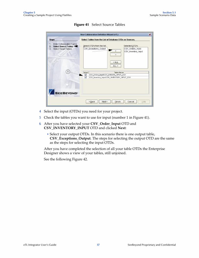
Figure 41 Select Source Tables
4 Select the input (OTDs) you need for your project.
5 Check the tables you want to use for input (number 1 in Figure 41).
6 After you have selected your CSV_Order_Input OTD and CSV_INVENTORY_INPUT OTD and clicked Next:
" Select your output OTDs. In this scenario there is one output table, CSV_Exceptions_Output. The steps for selecting the output OTD are the same as the steps for selecting the input OTDs.
After you have completed the selection of all your table OTDs the Enterprise Designer shows a view of your tables, still unjoined.
See the following Figure 42.
1
eTL Integrator User’s Guide 57 SeeBeyond Proprietary and Confidential
Chapter 5 Section 5.2Creating a Sample Project Using Flatfiles Mapping Tables
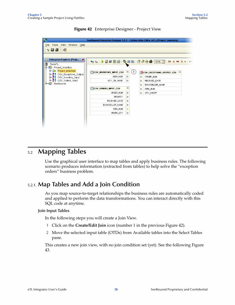
Figure 42 Enterprise Designer - Project View
5.2 Mapping TablesUse the graphical user interface to map tables and apply business rules. The following scenario produces information (extracted from tables) to help solve the “exception orders” business problem.
5.2.1. Map Tables and Add a Join ConditionAs you map source-to-target relationships the business rules are automatically coded and applied to perform the data transformations. You can interact directly with this SQL code at anytime.
Join Input Tables
In the following steps you will create a Join View.
1 Click on the Create/Edit Join icon (number 1 in the previous Figure 42).
2 Move the selected input table (OTDs) from Available tables into the Select Tables pane.
This creates a new join view, with no join condition set (yet). See the following Figure 43.
1
eTL Integrator User’s Guide 58 SeeBeyond Proprietary and Confidential
Chapter 5 Section 5.2Creating a Sample Project Using Flatfiles Mapping Tables
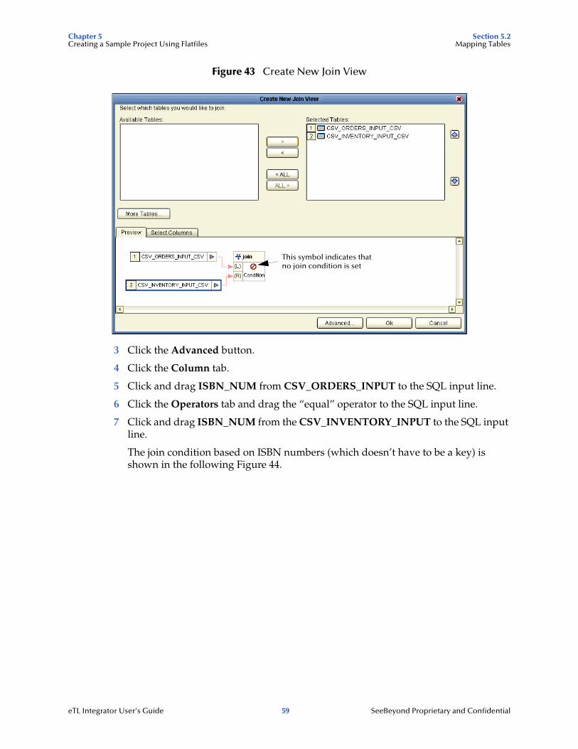
Figure 43 Create New Join View
3 Click the Advanced button.
4 Click the Column tab.
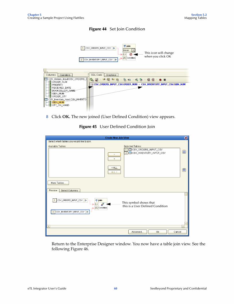
5 Click and drag ISBN_NUM from CSV_ORDERS_INPUT to the SQL input line.
6 Click the Operators tab and drag the “equal” operator to the SQL input line.
7 Click and drag ISBN_NUM from the CSV_INVENTORY_INPUT to the SQL input line.
The join condition based on ISBN numbers (which doesn’t have to be a key) is shown in the following Figure 44.
This symbol indicates thatno join condition is set
eTL Integrator User’s Guide 59 SeeBeyond Proprietary and Confidential
Chapter 5 Section 5.2Creating a Sample Project Using Flatfiles Mapping Tables
Figure 44 Set Join Condition
8 Click OK. The new joined (User Defined Condition) view appears.
Figure 45 User Defined Condition Join
Return to the Enterprise Designer window. You now have a table join view. See the following Figure 46.
This icon will changewhen you click OK
This symbol shows thatthis is a User Defined Condition
eTL Integrator User’s Guide 60 SeeBeyond Proprietary and Confidential
Chapter 5 Section 5.2Creating a Sample Project Using Flatfiles Mapping Tables
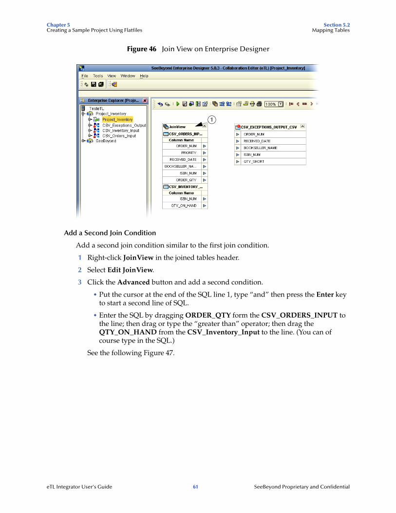
Figure 46 Join View on Enterprise Designer
Add a Second Join Condition
Add a second join condition similar to the first join condition.
1 Right-click JoinView in the joined tables header.
2 Select Edit JoinView.
3 Click the Advanced button and add a second condition.
" Put the cursor at the end of the SQL line 1, type “and” then press the Enter key to start a second line of SQL.
" Enter the SQL by dragging ORDER_QTY form the CSV_ORDERS_INPUT to the line; then drag or type the “greater than” operator; then drag the QTY_ON_HAND from the CSV_Inventory_Input to the line. (You can of course type in the SQL.)
See the following Figure 47.
1
eTL Integrator User’s Guide 61 SeeBeyond Proprietary and Confidential
Chapter 5 Section 5.2Creating a Sample Project Using Flatfiles Mapping Tables
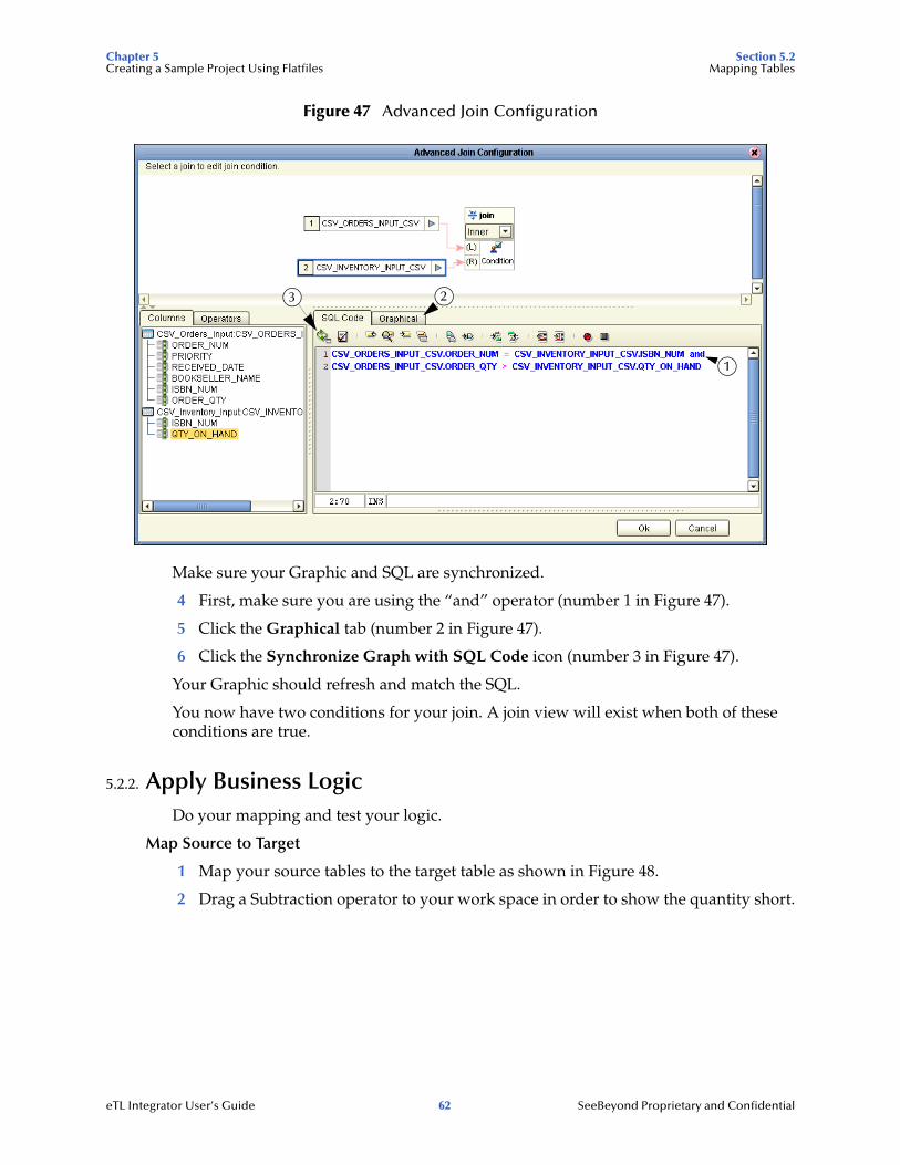
Figure 47 Advanced Join Configuration
Make sure your Graphic and SQL are synchronized.
4 First, make sure you are using the “and” operator (number 1 in Figure 47).
5 Click the Graphical tab (number 2 in Figure 47).
6 Click the Synchronize Graph with SQL Code icon (number 3 in Figure 47).
Your Graphic should refresh and match the SQL.
You now have two conditions for your join. A join view will exist when both of these conditions are true.
5.2.2. Apply Business LogicDo your mapping and test your logic.
Map Source to Target
1 Map your source tables to the target table as shown in Figure 48.
2 Drag a Subtraction operator to your work space in order to show the quantity short.
23
1
eTL Integrator User’s Guide 62 SeeBeyond Proprietary and Confidential
Chapter 5 Section 5.2Creating a Sample Project Using Flatfiles Mapping Tables
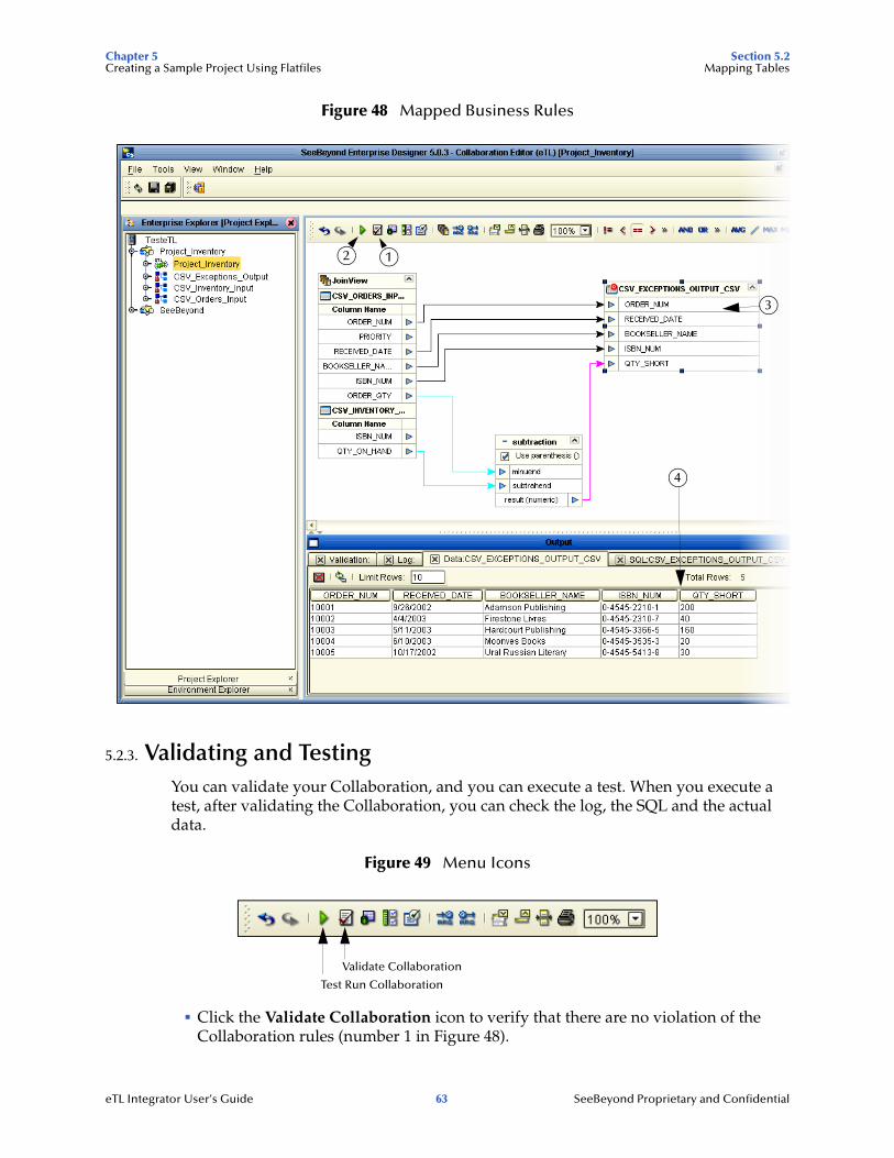
Figure 48 Mapped Business Rules
5.2.3. Validating and TestingYou can validate your Collaboration, and you can execute a test. When you execute a test, after validating the Collaboration, you can check the log, the SQL and the actual data.
Figure 49 Menu Icons
! Click the Validate Collaboration icon to verify that there are no violation of the Collaboration rules (number 1 in Figure 48).
2 1
3
4
Validate Collaboration
Test Run Collaboration
eTL Integrator User’s Guide 63 SeeBeyond Proprietary and Confidential
Chapter 5 Section 5.3Creating a Sample Project Using Flatfiles Connectivity Map
! Click the Test Run Collaboration icon to run your project (number 2 in Figure 48).
! Right-click the Target table and select “Show Data” (number 3 in Figure 48).
! Verify the accuracy of your logic and output data (number 4 in Figure 48).
5.3 Connectivity MapA Connectivity Map is used to configure the relational connections between your services and data.
5.3.1. Create a Connectivity MapCreate a Connectivity Map to graphically show the relation of your Service (which will contain your eTL Collaboration) and your source and target tables.
Drag Components to your Connectivity Map
1 Right-click your project (Project1) and select New and Connectivity Map.
Click the components you need and drag them to the work space.
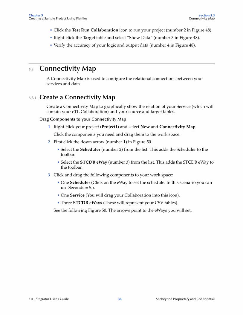
2 First click the down arrow (number 1) in Figure 50.
" Select the Scheduler (number 2) from the list. This adds the Scheduler to the toolbar.
" Select the STCDB eWay (number 3) from the list. This adds the STCDB eWay to the toolbar.
3 Click and drag the following components to your work space:
" One Scheduler (Click on the eWay to set the schedule. In this scenario you can use Seconds = 5.).
" One Service (You will drag your Collaboration into this icon).
" Three STCDB eWays (These will represent your CSV tables).
See the following Figure 50. The arrows point to the eWays you will set.
eTL Integrator User’s Guide 64 SeeBeyond Proprietary and Confidential
Chapter 5 Section 5.3Creating a Sample Project Using Flatfiles Connectivity Map
Figure 50 Connectivity Map
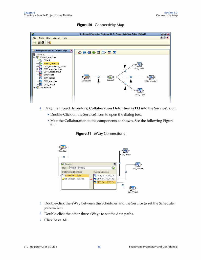
4 Drag the Project_Inventory, Collaboration Definition (eTL) into the Service1 icon.
" Double-Click on the Service1 icon to open the dialog box.
" Map the Collaboration to the components as shown. See the following Figure 51.
Figure 51 eWay Connections
5 Double-click the eWay between the Scheduler and the Service to set the Scheduler parameters.
6 Double-click the other three eWays to set the data paths.
7 Click Save All.
eTL Integrator User’s Guide 65 SeeBeyond Proprietary and Confidential
Chapter 5 Section 5.4Creating a Sample Project Using Flatfiles Deployment Profile for eTL
5.4 Deployment Profile for eTLThis section explains how to create and activate the Deployment Profile for the project scenario in this chapter. Before you can create the profile, you must create an Environment.
See the Deployment chapter in the eGate Integrator Tutorial for information about the Logical host, Environment and Bootstrap.
Create an Environment and Logical Host
An Environment is a collection of physical resources and their configurations that are used to host Project components. An Environment contains logical hosts and external systems.
1 Right-click your Project (Project_Inventory).
2 Click New and Deployment Profile.
3 Enter a Deployment and Environment name (or accept the defaults).
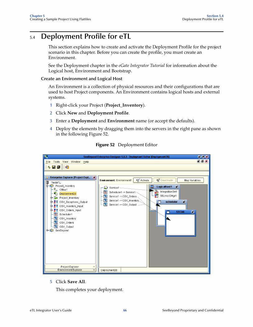
4 Deploy the elements by dragging them into the servers in the right pane as shown in the following Figure 52.
Figure 52 Deployment Editor
5 Click Save All.
This completes your deployment.
eTL Integrator User’s Guide 66 SeeBeyond Proprietary and Confidential
Chapter 5 Section 5.4Creating a Sample Project Using Flatfiles Deployment Profile for eTL
5.4.1 Run your ProjectWhen you deploy Project1, a deployment file is created and will later be picked up by the Logical Host. The Project you created with Enterprise Designer will be “code generated” into a package that will be passed to the Repository. The Logical Host will pick up this package from the Repository.
If you want to do a “hot deploy,” which means that the Logical Host will pick up the current package in real time after the bootstrap has been started, you could click YES in the Activate Dialog box when prompted “Do you wish to apply Logical host(s) immediately?” (See below).
Activate Environment
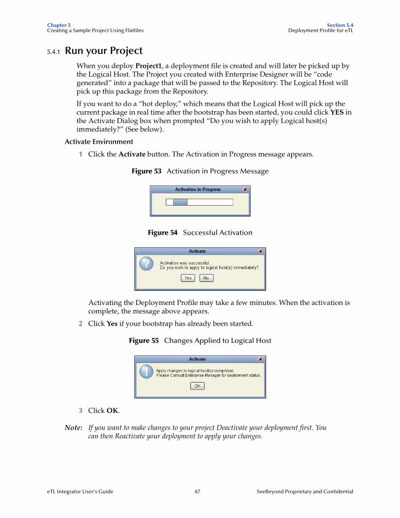
1 Click the Activate button. The Activation in Progress message appears.
Figure 53 Activation in Progress Message
Figure 54 Successful Activation
Activating the Deployment Profile may take a few minutes. When the activation is complete, the message above appears.
2 Click Yes if your bootstrap has already been started.
Figure 55 Changes Applied to Logical Host
3 Click OK.
Note: If you want to make changes to your project Deactivate your deployment first. You can then Reactivate your deployment to apply your changes.
eTL Integrator User’s Guide 67 SeeBeyond Proprietary and Confidential
Chapter 5 Section 5.5Creating a Sample Project Using Flatfiles Run the Bootstrap and Management Agent
5.5 Run the Bootstrap and Management AgentThe Bootstrap process executes your Project and begins the process of polling your input data. The Bootstrap process is run from a command prompt or by executing bootstrap.bat. Bootstrap will pick up the deployment profile the first time it runs; after that you would redeploy to apply the most recent changes to the logical host.
Logical Host Overview
At run time, the Logical Host bootstrap script starts the bootstrap Java program that downloads the Management Agent, the Message Server, and the Integration Server from the Repository. The Management Agent is then started, which in turn starts the Message Server(s) and Integration Server(s).
5.5.1 Run the Bootstrap
Note: The Bootstrap command is case sensitive on Windows platforms.
Two ways to run the bootstrap are explained below:
Edit Properties and run bootstrap.bat (method 1)
You can edit the configuration file: Logical-host.properties. Ensure that the Logical Host is not running. The required fields are explained below:
1 Navigate to the following file (depending your installation’s setup): Ican50>logicalhost>bootstrap>config>logical_host.properties.
These properties are automatically persisted by the bootstrap sequence. Default properties are used if none are provided at the command line.
2 Edit: repository.url=http://localhost:12000/TesteTL
localhost:12000 the default port number. Test is the repository name in this example.
3 Edit: repository.username=Administrator
Enter the Administrator name.
4 Enter the repository password: repository.password=
repository.password: (USER CONFIGURABLE). Plain text form of password used for connecting to the repository. Any value provided here will be cleared out by the system and written in encrypted form to the repository.password.encrypted field.
5 Edit: logical.host.environment.name=Environment1
Enter an environment name that will be used when you deploy your project.
6 Edit: logical.host.name=LogicalHost1
logical.host.environment.name: (USER CONFIGURABLE). Specifies the name of the environment containing the current logical host.
After you have configured this file you can execute Bootstrap.bat.
Example: C:\Ican50\logicalhost\bootstrap\bin\Bootstrap.bat
eTL Integrator User’s Guide 68 SeeBeyond Proprietary and Confidential
Chapter 5 Section 5.6Creating a Sample Project Using Flatfiles Verify the Output Data
Note: Do not enter spaces before or after the equal sign (=) and the property values. Spaces are allowed only in the value itself.
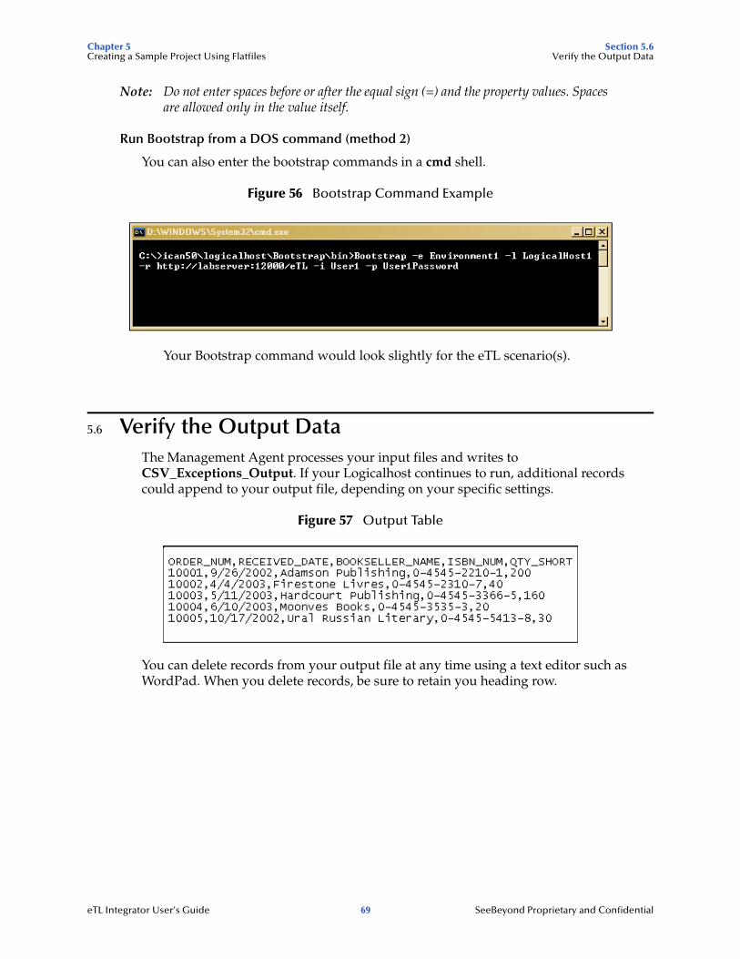
Run Bootstrap from a DOS command (method 2)
You can also enter the bootstrap commands in a cmd shell.
Figure 56 Bootstrap Command Example
Your Bootstrap command would look slightly for the eTL scenario(s).
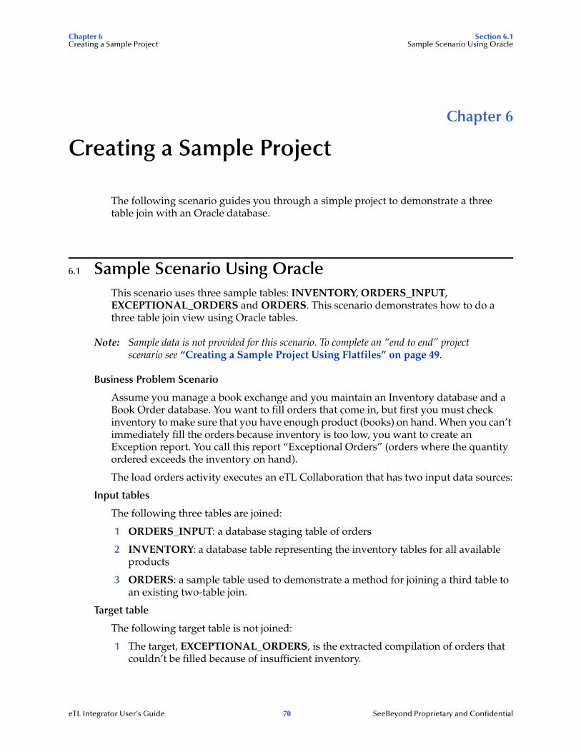
5.6 Verify the Output DataThe Management Agent processes your input files and writes to CSV_Exceptions_Output. If your Logicalhost continues to run, additional records could append to your output file, depending on your specific settings.
Figure 57 Output Table
You can delete records from your output file at any time using a text editor such as WordPad. When you delete records, be sure to retain you heading row.
eTL Integrator User’s Guide 69 SeeBeyond Proprietary and Confidential
Chapter 6 Section 6.1Creating a Sample Project Sample Scenario Using Oracle
Chapter 6
Creating a Sample Project
The following scenario guides you through a simple project to demonstrate a three table join with an Oracle database.
6.1 Sample Scenario Using OracleThis scenario uses three sample tables: INVENTORY, ORDERS_INPUT, EXCEPTIONAL_ORDERS and ORDERS. This scenario demonstrates how to do a three table join view using Oracle tables.
Note: Sample data is not provided for this scenario. To complete an “end to end” project scenario see “Creating a Sample Project Using Flatfiles” on page 49.
Business Problem Scenario
Assume you manage a book exchange and you maintain an Inventory database and a Book Order database. You want to fill orders that come in, but first you must check inventory to make sure that you have enough product (books) on hand. When you can’t immediately fill the orders because inventory is too low, you want to create an Exception report. You call this report “Exceptional Orders” (orders where the quantity ordered exceeds the inventory on hand).
The load orders activity executes an eTL Collaboration that has two input data sources:
Input tables
The following three tables are joined:
1 ORDERS_INPUT: a database staging table of orders
2 INVENTORY: a database table representing the inventory tables for all available products
3 ORDERS: a sample table used to demonstrate a method for joining a third table to an existing two-table join.
Target table
The following target table is not joined:
1 The target, EXCEPTIONAL_ORDERS, is the extracted compilation of orders that couldn’t be filled because of insufficient inventory.
eTL Integrator User’s Guide 70 SeeBeyond Proprietary and Confidential
Chapter 6 Section 6.2Creating a Sample Project Starting the Enterprise Designer
The eTL logic reads all orders from the staging table(s) and inserts some into the EXCEPTIONAL_ORDERS table. Depending on the inventory information, individual orders go into specific tables. The eTL Collaboration looks at each entry in the ORDERS_INPUT table and compares the ordered quantity against current inventory in the INVENTORY table. If the requested quantity exceeds the inventory, the order is entered into the EXCEPTIONAL_ORDERS table.
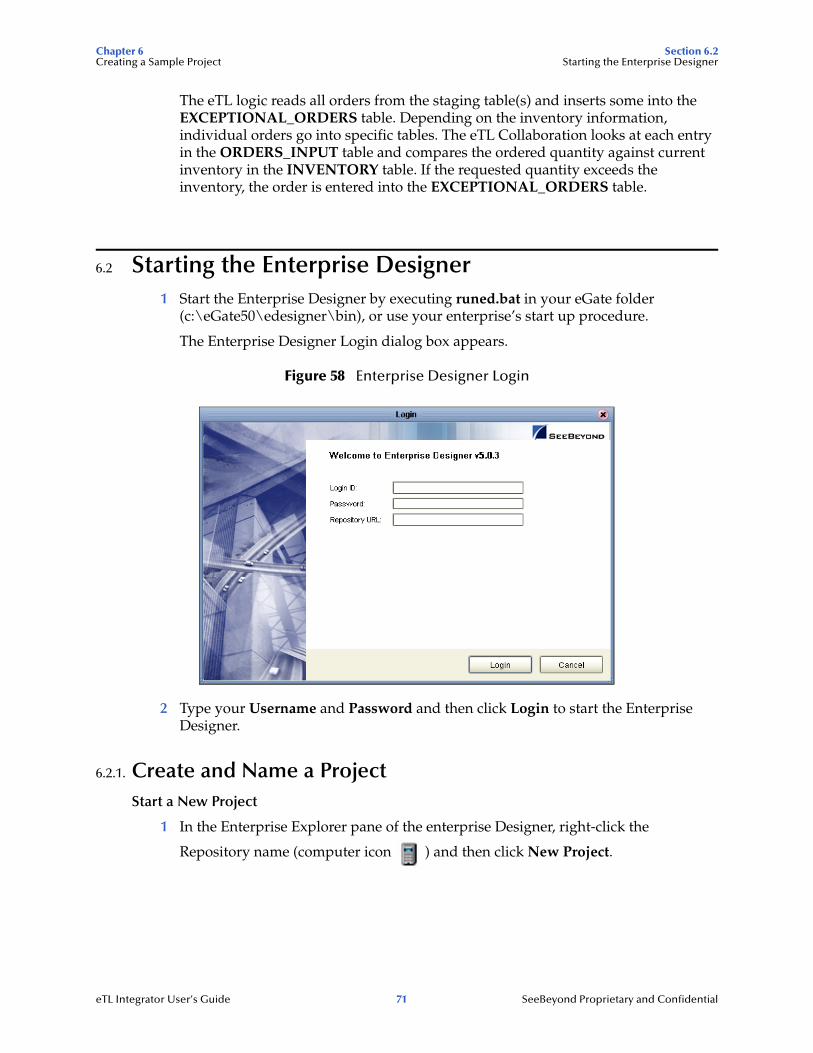
6.2 Starting the Enterprise Designer1 Start the Enterprise Designer by executing runed.bat in your eGate folder
(c:\eGate50\edesigner\bin), or use your enterprise’s start up procedure.
The Enterprise Designer Login dialog box appears.
Figure 58 Enterprise Designer Login
2 Type your Username and Password and then click Login to start the Enterprise Designer.
6.2.1. Create and Name a ProjectStart a New Project
1 In the Enterprise Explorer pane of the enterprise Designer, right-click the
Repository name (computer icon ) and then click New Project.
eTL Integrator User’s Guide 71 SeeBeyond Proprietary and Confidential
Chapter 6 Section 6.2Creating a Sample Project Starting the Enterprise Designer
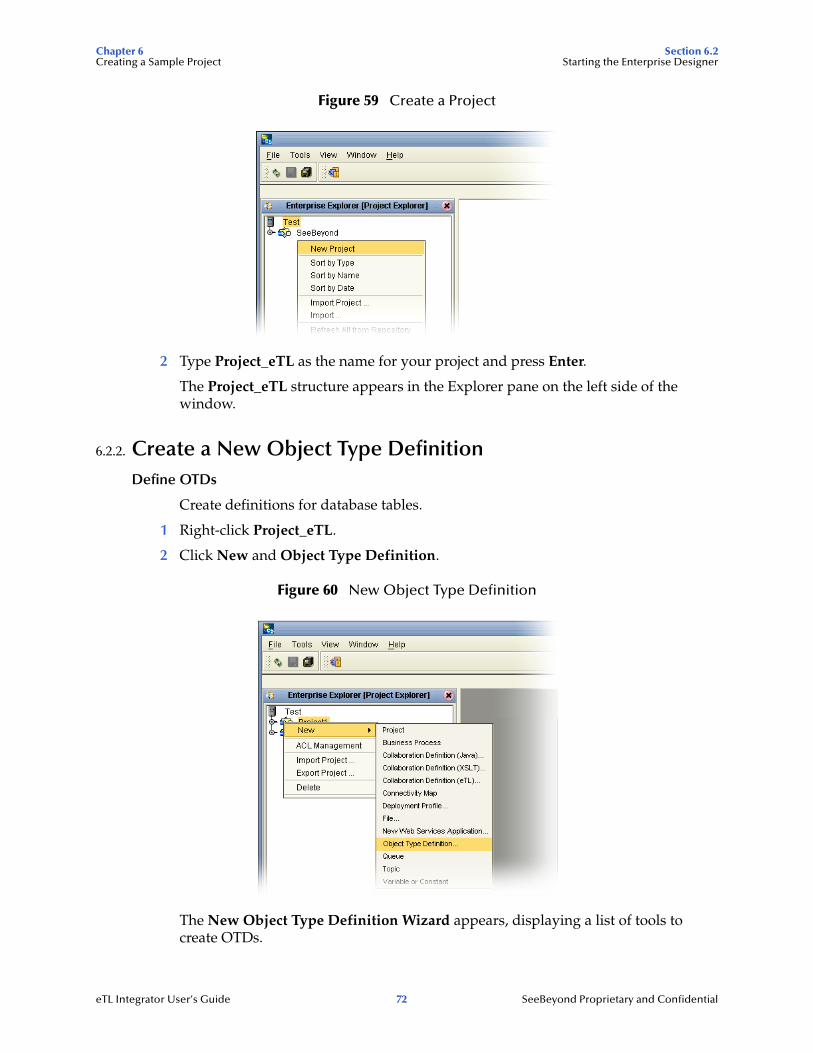
Figure 59 Create a Project
2 Type Project_eTL as the name for your project and press Enter.
The Project_eTL structure appears in the Explorer pane on the left side of the window.
6.2.2. Create a New Object Type DefinitionDefine OTDs
Create definitions for database tables.
1 Right-click Project_eTL.
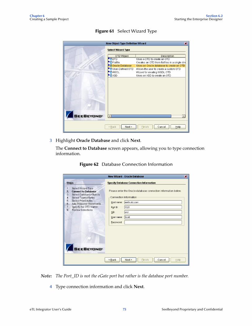
2 Click New and Object Type Definition.
Figure 60 New Object Type Definition
The New Object Type Definition Wizard appears, displaying a list of tools to create OTDs.
eTL Integrator User’s Guide 72 SeeBeyond Proprietary and Confidential
Chapter 6 Section 6.2Creating a Sample Project Starting the Enterprise Designer
Figure 61 Select Wizard Type
3 Highlight Oracle Database and click Next.
The Connect to Database screen appears, allowing you to type connection information.
Figure 62 Database Connection Information
Note: The Port_ID is not the eGate port but rather is the database port number.
4 Type connection information and click Next.
eTL Integrator User’s Guide 73 SeeBeyond Proprietary and Confidential

Chapter 6 Section 6.2Creating a Sample Project Starting the Enterprise Designer
6.2.3. Select Database Objects Select Tables and Table Views
In the following steps select database objects and table views to use in your project.
Figure 63 Select Database Objects
1 Check the Tables/Views box and click Next.
The Select Tables/Views window appears.
Figure 64 Select Tables/Views
eTL Integrator User’s Guide 74 SeeBeyond Proprietary and Confidential
Chapter 6 Section 6.2Creating a Sample Project Starting the Enterprise Designer
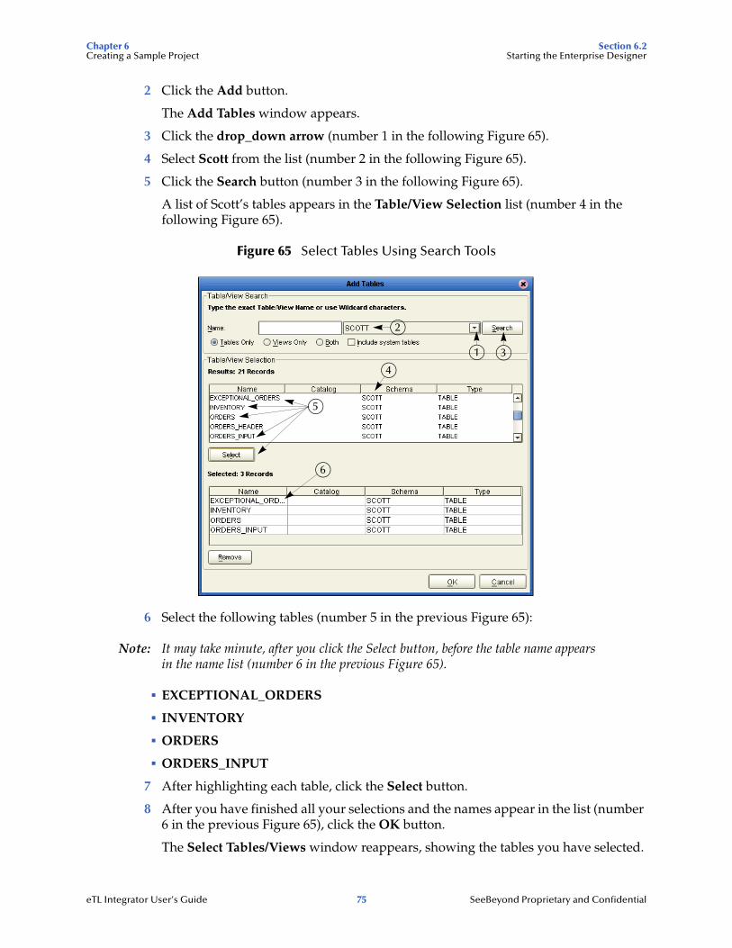
2 Click the Add button.
The Add Tables window appears.
3 Click the drop_down arrow (number 1 in the following Figure 65).
4 Select Scott from the list (number 2 in the following Figure 65).
5 Click the Search button (number 3 in the following Figure 65).
A list of Scott’s tables appears in the Table/View Selection list (number 4 in the following Figure 65).
Figure 65 Select Tables Using Search Tools
6 Select the following tables (number 5 in the previous Figure 65):
Note: It may take minute, after you click the Select button, before the table name appears in the name list (number 6 in the previous Figure 65).
! EXCEPTIONAL_ORDERS
! INVENTORY
! ORDERS
! ORDERS_INPUT
7 After highlighting each table, click the Select button.
8 After you have finished all your selections and the names appear in the list (number 6 in the previous Figure 65), click the OK button.
The Select Tables/Views window reappears, showing the tables you have selected.
1
2
3
4
5
6
eTL Integrator User’s Guide 75 SeeBeyond Proprietary and Confidential

Chapter 6 Section 6.2Creating a Sample Project Starting the Enterprise Designer
Figure 66 Select Tables
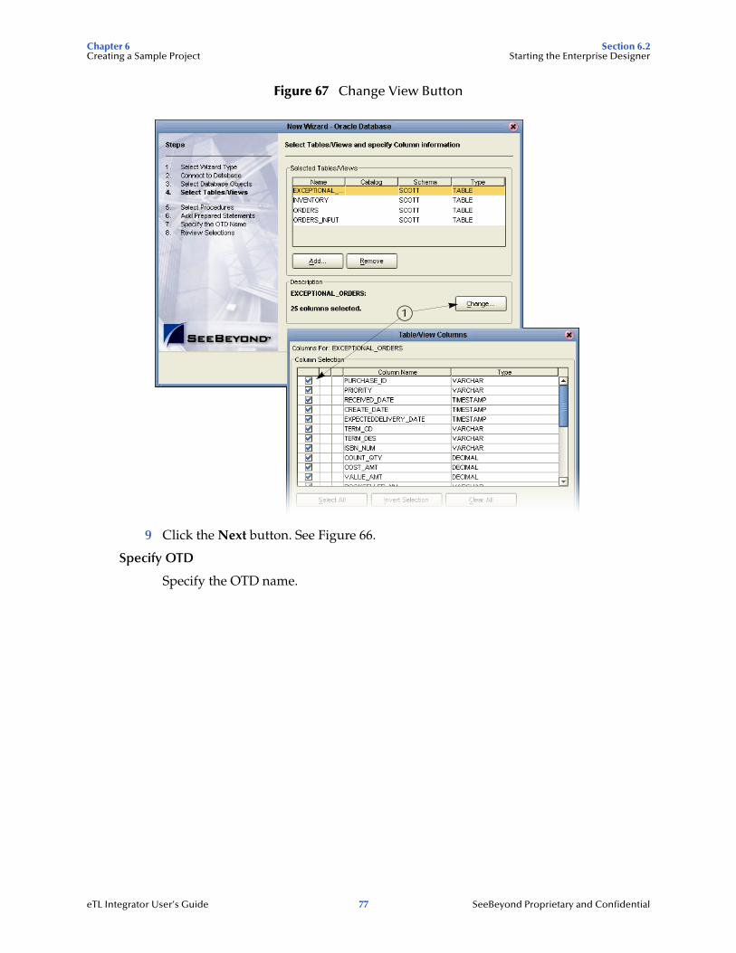
Note: You could click on the Change button and limit the number of fields to display in your tables by unchecking some of the columns. The checked columns will display. Refer to number 1 in the following Figure 67. In this scenario we will display all fields.
eTL Integrator User’s Guide 76 SeeBeyond Proprietary and Confidential
Chapter 6 Section 6.2Creating a Sample Project Starting the Enterprise Designer
Figure 67 Change View Button
9 Click the Next button. See Figure 66.
Specify OTD
Specify the OTD name.
1
eTL Integrator User’s Guide 77 SeeBeyond Proprietary and Confidential
Chapter 6 Section 6.2Creating a Sample Project Starting the Enterprise Designer
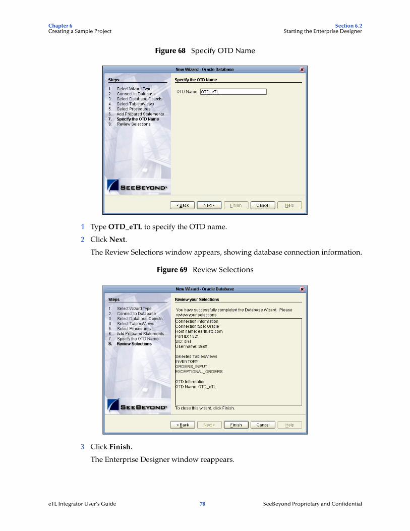
Figure 68 Specify OTD Name
1 Type OTD_eTL to specify the OTD name.
2 Click Next.
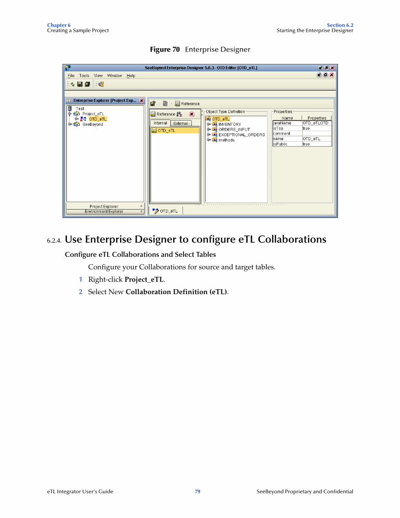
The Review Selections window appears, showing database connection information.
Figure 69 Review Selections
3 Click Finish.
The Enterprise Designer window reappears.
eTL Integrator User’s Guide 78 SeeBeyond Proprietary and Confidential
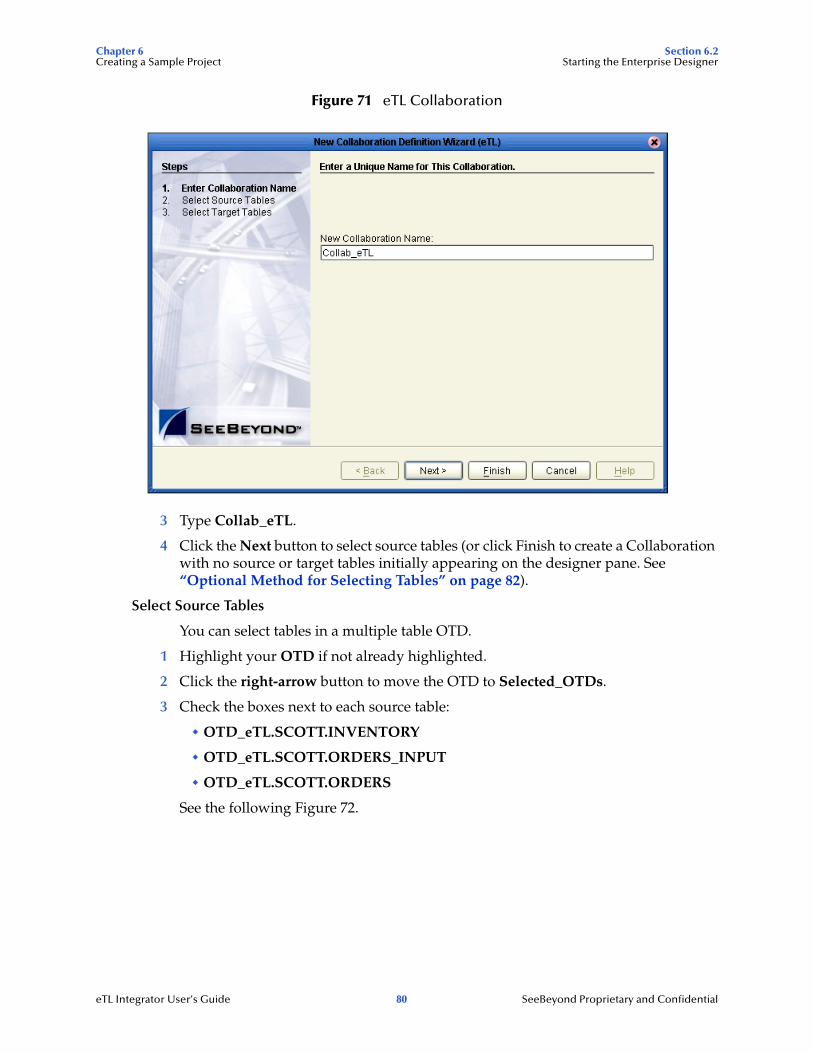
Chapter 6 Section 6.2Creating a Sample Project Starting the Enterprise Designer
Figure 70 Enterprise Designer
6.2.4. Use Enterprise Designer to configure eTL CollaborationsConfigure eTL Collaborations and Select Tables
Configure your Collaborations for source and target tables.
1 Right-click Project_eTL.
2 Select New Collaboration Definition (eTL).
eTL Integrator User’s Guide 79 SeeBeyond Proprietary and Confidential
Chapter 6 Section 6.2Creating a Sample Project Starting the Enterprise Designer
Figure 71 eTL Collaboration
3 Type Collab_eTL.
4 Click the Next button to select source tables (or click Finish to create a Collaboration with no source or target tables initially appearing on the designer pane. See “Optional Method for Selecting Tables” on page 82).
Select Source Tables
You can select tables in a multiple table OTD.
1 Highlight your OTD if not already highlighted.
2 Click the right-arrow button to move the OTD to Selected_OTDs.
3 Check the boxes next to each source table:
" OTD_eTL.SCOTT.INVENTORY
" OTD_eTL.SCOTT.ORDERS_INPUT
" OTD_eTL.SCOTT.ORDERS
See the following Figure 72.
eTL Integrator User’s Guide 80 SeeBeyond Proprietary and Confidential
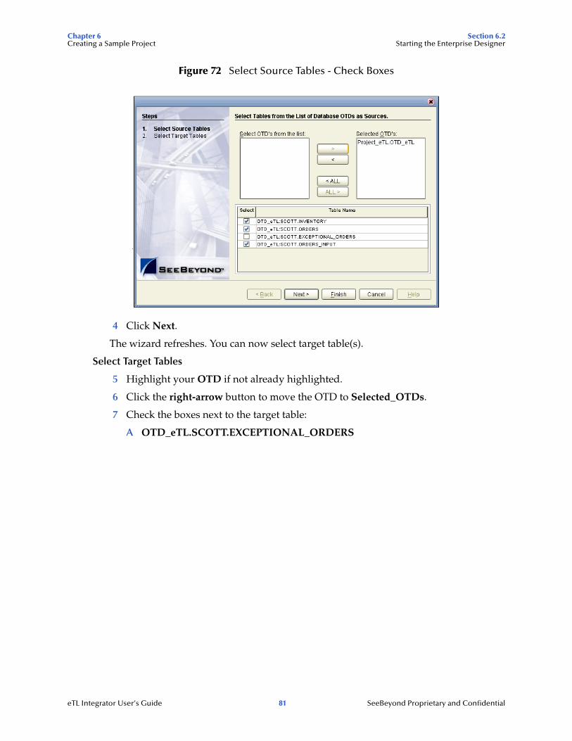
Chapter 6 Section 6.2Creating a Sample Project Starting the Enterprise Designer
Figure 72 Select Source Tables - Check Boxes
4 Click Next.
The wizard refreshes. You can now select target table(s).
Select Target Tables
5 Highlight your OTD if not already highlighted.
6 Click the right-arrow button to move the OTD to Selected_OTDs.
7 Check the boxes next to the target table:
A OTD_eTL.SCOTT.EXCEPTIONAL_ORDERS
eTL Integrator User’s Guide 81 SeeBeyond Proprietary and Confidential
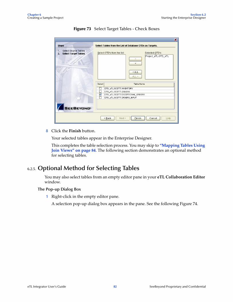
Chapter 6 Section 6.2Creating a Sample Project Starting the Enterprise Designer
Figure 73 Select Target Tables - Check Boxes
8 Click the Finish button.
Your selected tables appear in the Enterprise Designer.
This completes the table selection process. You may skip to “Mapping Tables Using Join Views” on page 84. The following section demonstrates an optional method for selecting tables.
6.2.5. Optional Method for Selecting TablesYou may also select tables from an empty editor pane in your eTL Collaboration Editor window.
The Pop-up Dialog Box
1 Right-click in the empty editor pane.
A selection pop-up dialog box appears in the pane. See the following Figure 74.
eTL Integrator User’s Guide 82 SeeBeyond Proprietary and Confidential

Chapter 6 Section 6.2Creating a Sample Project Starting the Enterprise Designer
Figure 74 Options Pop-up Dialog Box
2 Click Select Tables... from the options.
3 Drag and drop tables from Enterprise Explorer.
eTL Integrator User’s Guide 83 SeeBeyond Proprietary and Confidential
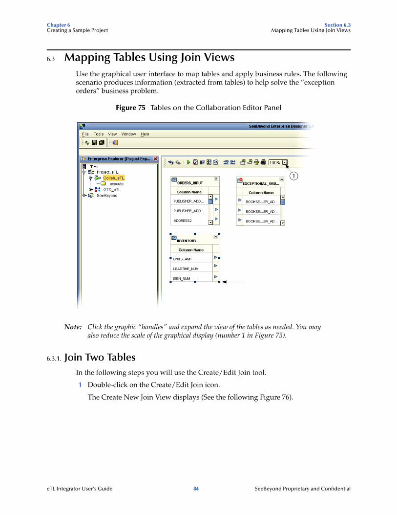
Chapter 6 Section 6.3Creating a Sample Project Mapping Tables Using Join Views
6.3 Mapping Tables Using Join ViewsUse the graphical user interface to map tables and apply business rules. The following scenario produces information (extracted from tables) to help solve the “exception orders” business problem.
Figure 75 Tables on the Collaboration Editor Panel
Note: Click the graphic “handles” and expand the view of the tables as needed. You may also reduce the scale of the graphical display (number 1 in Figure 75).
6.3.1. Join Two TablesIn the following steps you will use the Create/Edit Join tool.
1 Double-click on the Create/Edit Join icon.
The Create New Join View displays (See the following Figure 76).
1
eTL Integrator User’s Guide 84 SeeBeyond Proprietary and Confidential
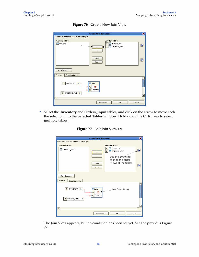
Chapter 6 Section 6.3Creating a Sample Project Mapping Tables Using Join Views
Figure 76 Create New Join View
2 Select the, Inventory and Orders_input tables, and click on the arrow to move each the selection into the Selected Tables window. Hold down the CTRL key to select multiple tables.
Figure 77 Edit Join View (2)
The Join View appears, but no condition has been set yet. See the previous Figure 77.
No Condition
Use the arrows tochange the order(view) of the tables
eTL Integrator User’s Guide 85 SeeBeyond Proprietary and Confidential
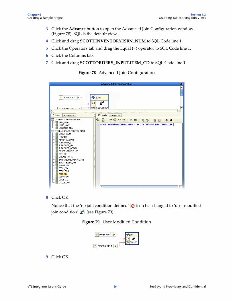
Chapter 6 Section 6.3Creating a Sample Project Mapping Tables Using Join Views
3 Click the Advance button to open the Advanced Join Configuration window (Figure 78). SQL is the default view.
4 Click and drag SCOTT.INVENTORY.ISBN_NUM to SQL Code line 1.
5 Click the Operators tab and drag the Equal (=) operator to SQL Code line 1.
6 Click the Columns tab.
7 Click and drag SCOTT.ORDERS_INPUT.ITEM_CD to SQL Code line 1.
Figure 78 Advanced Join Configuration
8 Click OK.
Notice that the ‘no join condition defined’ icon has changed to ‘user modified
join condition’ (see Figure 79).
Figure 79 User Modified Condition
9 Click OK.
eTL Integrator User’s Guide 86 SeeBeyond Proprietary and Confidential
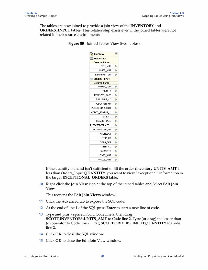
Chapter 6 Section 6.3Creating a Sample Project Mapping Tables Using Join Views
The tables are now joined to provide a join view of the INVENTORY and ORDERS_INPUT tables. This relationship exists even if the joined tables were not related in their source environments.
Figure 80 Joined Tables View (two tables)
If the quantity on hand isn’t sufficient to fill the order (Inventory UNITS_AMT is less than Orders_Input QUANTITY, you want to view “exceptional” information in the target EXCEPTIONAL_ORDERS table.
10 Right-click the Join View icon at the top of the joined tables and Select Edit Join View.
This reopens the Edit Join Views window.
11 Click the Advanced tab to expose the SQL code.
12 At the end of line 1 of the SQL press Enter to start a new line of code.
13 Type and plus a space in SQL Code line 2, then drag SCOTT.INVENTORY.UNITS_AMT to Code line 2. Type (or drag) the lesser than (<) operator to Code line 2. Drag SCOTT.ORDERS_INPUT.QUANTITY to Code line 2.
14 Click OK to close the SQL window.
15 Click OK to close the Edit Join View window.
eTL Integrator User’s Guide 87 SeeBeyond Proprietary and Confidential
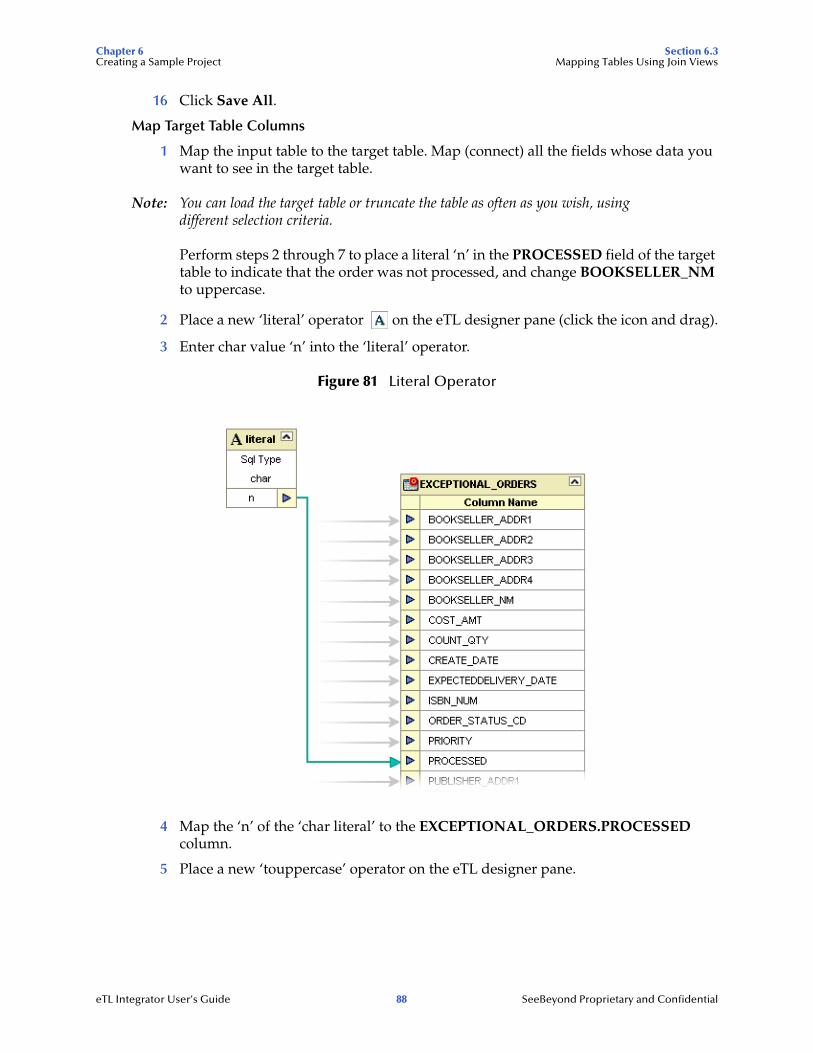
Chapter 6 Section 6.3Creating a Sample Project Mapping Tables Using Join Views
16 Click Save All.
Map Target Table Columns
1 Map the input table to the target table. Map (connect) all the fields whose data you want to see in the target table.
Note: You can load the target table or truncate the table as often as you wish, using different selection criteria.
Perform steps 2 through 7 to place a literal ‘n’ in the PROCESSED field of the target table to indicate that the order was not processed, and change BOOKSELLER_NM to uppercase.
2 Place a new ‘literal’ operator on the eTL designer pane (click the icon and drag).
3 Enter char value ‘n’ into the ‘literal’ operator.
Figure 81 Literal Operator
4 Map the ‘n’ of the ‘char literal’ to the EXCEPTIONAL_ORDERS.PROCESSED column.
5 Place a new ‘touppercase’ operator on the eTL designer pane.
eTL Integrator User’s Guide 88 SeeBeyond Proprietary and Confidential
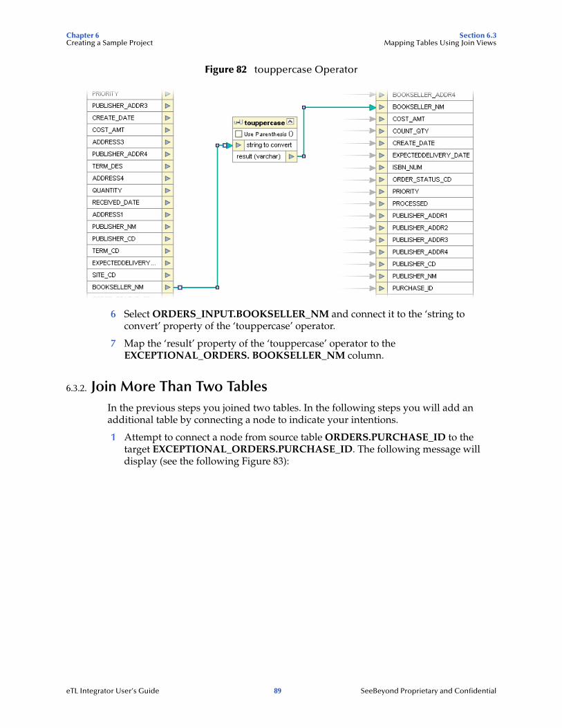
Chapter 6 Section 6.3Creating a Sample Project Mapping Tables Using Join Views
Figure 82 touppercase Operator
6 Select ORDERS_INPUT.BOOKSELLER_NM and connect it to the ‘string to convert’ property of the ‘touppercase’ operator.
7 Map the ‘result’ property of the ‘touppercase’ operator to the EXCEPTIONAL_ORDERS. BOOKSELLER_NM column.
6.3.2. Join More Than Two TablesIn the previous steps you joined two tables. In the following steps you will add an additional table by connecting a node to indicate your intentions.
1 Attempt to connect a node from source table ORDERS.PURCHASE_ID to the target EXCEPTIONAL_ORDERS.PURCHASE_ID. The following message will display (see the following Figure 83):
eTL Integrator User’s Guide 89 SeeBeyond Proprietary and Confidential
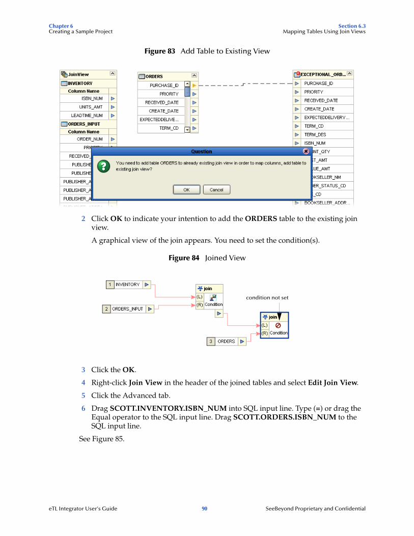
Chapter 6 Section 6.3Creating a Sample Project Mapping Tables Using Join Views
Figure 83 Add Table to Existing View
2 Click OK to indicate your intention to add the ORDERS table to the existing join view.
A graphical view of the join appears. You need to set the condition(s).
Figure 84 Joined View
3 Click the OK.
4 Right-click Join View in the header of the joined tables and select Edit Join View.
5 Click the Advanced tab.
6 Drag SCOTT.INVENTORY.ISBN_NUM into SQL input line. Type (=) or drag the Equal operator to the SQL input line. Drag SCOTT.ORDERS.ISBN_NUM to the SQL input line.
See Figure 85.
condition not set
eTL Integrator User’s Guide 90 SeeBeyond Proprietary and Confidential
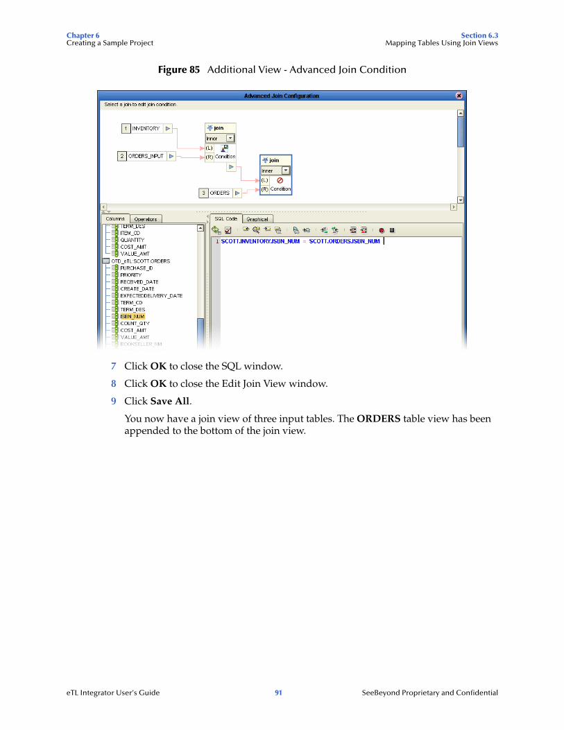
Chapter 6 Section 6.3Creating a Sample Project Mapping Tables Using Join Views
Figure 85 Additional View - Advanced Join Condition
7 Click OK to close the SQL window.
8 Click OK to close the Edit Join View window.
9 Click Save All.
You now have a join view of three input tables. The ORDERS table view has been appended to the bottom of the join view.
eTL Integrator User’s Guide 91 SeeBeyond Proprietary and Confidential
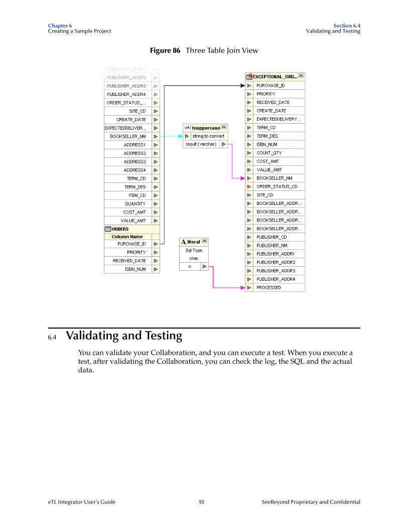
Chapter 6 Section 6.4Creating a Sample Project Validating and Testing
Figure 86 Three Table Join View
6.4 Validating and TestingYou can validate your Collaboration, and you can execute a test. When you execute a test, after validating the Collaboration, you can check the log, the SQL and the actual data.
eTL Integrator User’s Guide 92 SeeBeyond Proprietary and Confidential
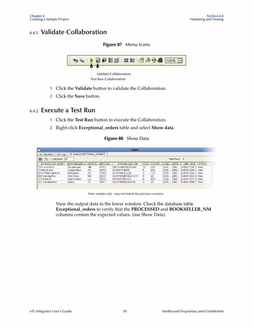
Chapter 6 Section 6.4Creating a Sample Project Validating and Testing
6.4.1. Validate Collaboration
Figure 87 Menu Icons
1 Click the Validate button to validate the Collaboration.
2 Click the Save button.
6.4.2. Execute a Test Run1 Click the Test Run button to execute the Collaboration.
2 Right-click Exceptional_orders table and select Show data.
Figure 88 Show Data
View the output data in the lower window. Check the database table Exceptional_orders to verify that the PROCESSED and BOOKSELLER_NM columns contain the expected values. (use Show Data).
Validate Collaboration
Test Run Collaboration
Note: sample only - may not match the previous scenario.
eTL Integrator User’s Guide 93 SeeBeyond Proprietary and Confidential
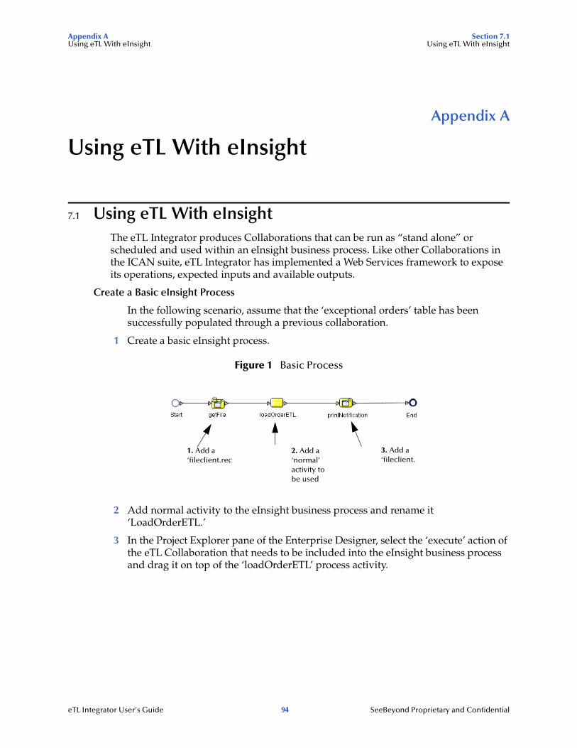
Appendix A Section 7.1Using eTL With eInsight Using eTL With eInsight
Appendix A
Using eTL With eInsight
7.1 Using eTL With eInsightThe eTL Integrator produces Collaborations that can be run as “stand alone” or scheduled and used within an eInsight business process. Like other Collaborations in the ICAN suite, eTL Integrator has implemented a Web Services framework to expose its operations, expected inputs and available outputs.
Create a Basic eInsight Process
In the following scenario, assume that the ‘exceptional orders’ table has been successfully populated through a previous collaboration.
1 Create a basic eInsight process.
Figure 1 Basic Process
2 Add normal activity to the eInsight business process and rename it ‘LoadOrderETL.’
3 In the Project Explorer pane of the Enterprise Designer, select the ‘execute’ action of the eTL Collaboration that needs to be included into the eInsight business process and drag it on top of the ‘loadOrderETL’ process activity.
1. Add a ‘fileclient.rec
2. Add a ‘normal’ activity to be used
3. Add a ‘fileclient.
eTL Integrator User’s Guide 94 SeeBeyond Proprietary and Confidential
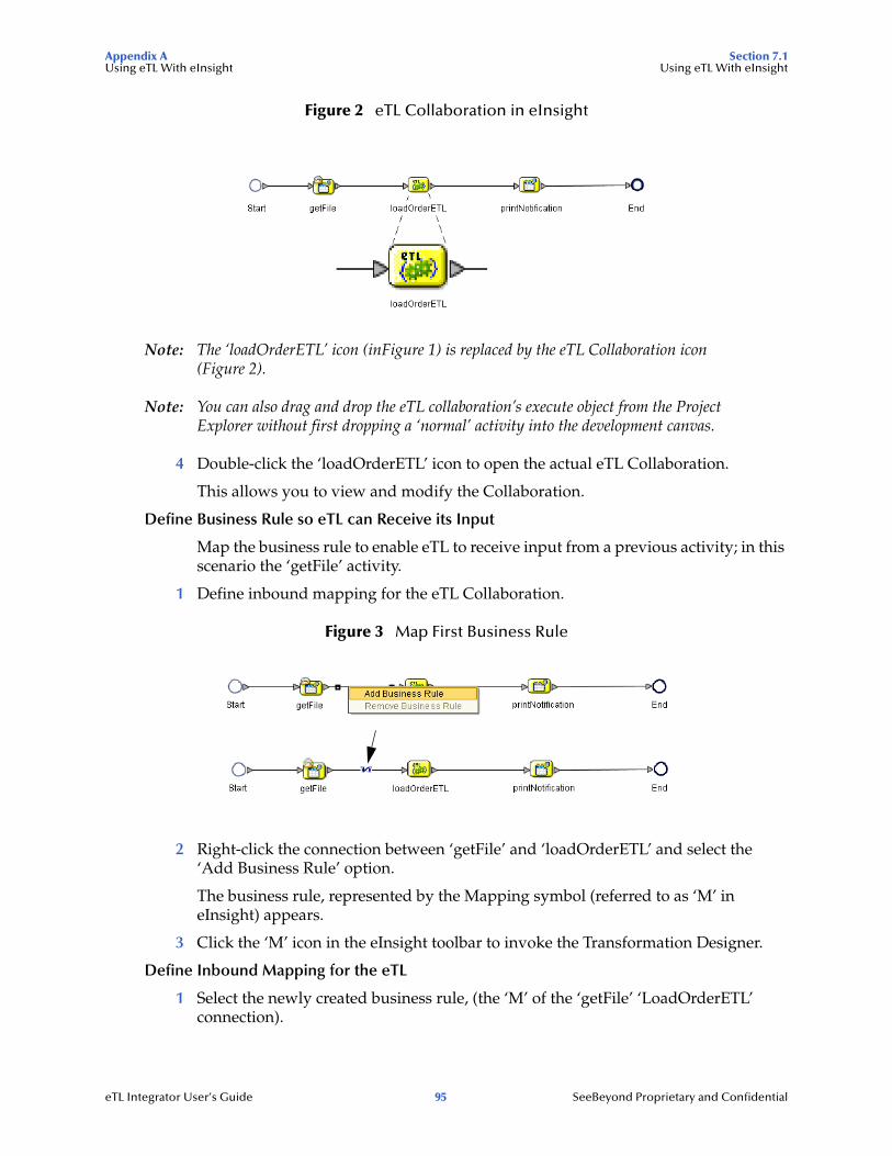
Appendix A Section 7.1Using eTL With eInsight Using eTL With eInsight
Figure 2 eTL Collaboration in eInsight
Note: The ‘loadOrderETL’ icon (inFigure 1) is replaced by the eTL Collaboration icon (Figure 2).
Note: You can also drag and drop the eTL collaboration’s execute object from the Project Explorer without first dropping a ‘normal’ activity into the development canvas.
4 Double-click the ‘loadOrderETL’ icon to open the actual eTL Collaboration.
This allows you to view and modify the Collaboration.
Define Business Rule so eTL can Receive its Input
Map the business rule to enable eTL to receive input from a previous activity; in this scenario the ‘getFile’ activity.
1 Define inbound mapping for the eTL Collaboration.
Figure 3 Map First Business Rule
2 Right-click the connection between ‘getFile’ and ‘loadOrderETL’ and select the ‘Add Business Rule’ option.
The business rule, represented by the Mapping symbol (referred to as ‘M’ in eInsight) appears.
3 Click the ‘M’ icon in the eInsight toolbar to invoke the Transformation Designer.
Define Inbound Mapping for the eTL
1 Select the newly created business rule, (the ‘M’ of the ‘getFile’ ‘LoadOrderETL’ connection).
eTL Integrator User’s Guide 95 SeeBeyond Proprietary and Confidential
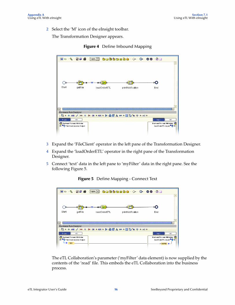
Appendix A Section 7.1Using eTL With eInsight Using eTL With eInsight
2 Select the ‘M’ icon of the eInsight toolbar.
The Transformation Designer appears.
Figure 4 Define Inbound Mapping
3 Expand the ‘FileClient’ operator in the left pane of the Transformation Designer.
4 Expand the ‘loadOrderETL’ operator in the right pane of the Transformation Designer.
5 Connect ‘text’ data in the left pane to ‘myFilter’ data in the right pane. See the following Figure 5.
Figure 5 Define Mapping - Connect Text
The eTL Collaboration’s parameter (‘myFilter’ data element) is now supplied by the contents of the ‘read’ file. This embeds the eTL Collaboration into the business process.
eTL Integrator User’s Guide 96 SeeBeyond Proprietary and Confidential
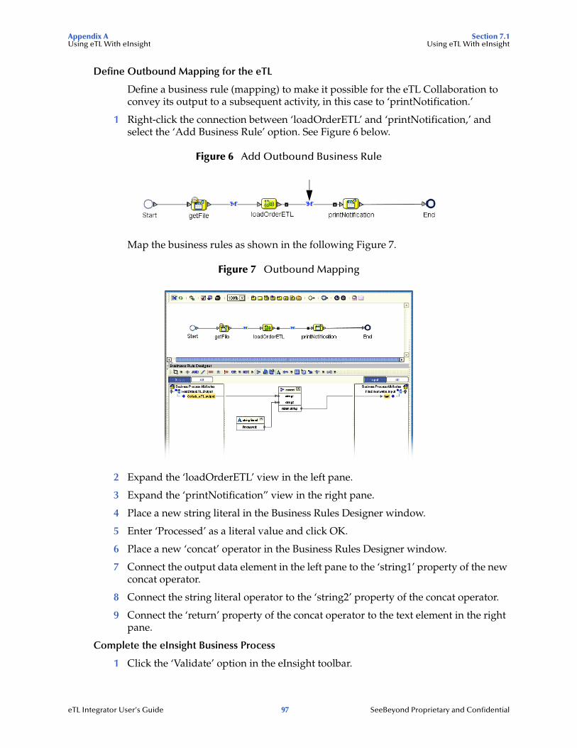
Appendix A Section 7.1Using eTL With eInsight Using eTL With eInsight
Define Outbound Mapping for the eTL
Define a business rule (mapping) to make it possible for the eTL Collaboration to convey its output to a subsequent activity, in this case to ‘printNotification.’
1 Right-click the connection between ‘loadOrderETL’ and ‘printNotification,’ and select the ‘Add Business Rule’ option. See Figure 6 below.
Figure 6 Add Outbound Business Rule
Map the business rules as shown in the following Figure 7.
Figure 7 Outbound Mapping
2 Expand the ‘loadOrderETL’ view in the left pane.
3 Expand the ‘printNotification” view in the right pane.
4 Place a new string literal in the Business Rules Designer window.
5 Enter ‘Processed’ as a literal value and click OK.
6 Place a new ‘concat’ operator in the Business Rules Designer window.
7 Connect the output data element in the left pane to the ‘string1’ property of the new concat operator.
8 Connect the string literal operator to the ‘string2’ property of the concat operator.
9 Connect the ‘return’ property of the concat operator to the text element in the right pane.
Complete the eInsight Business Process
1 Click the ‘Validate’ option in the eInsight toolbar.
eTL Integrator User’s Guide 97 SeeBeyond Proprietary and Confidential

Appendix A Section 7.1Using eTL With eInsight Using eTL With eInsight
2 Click the ‘Synchronize’ option in the eInsight toolbar.
3 Click the ‘Show Business’ option in the eInsight toolbar to show the generated BPEL source code.
The business process exposes itself as a Web Service. You now have embedded your eTL Collaboration into a business process that can be invoked as a Web Service.
eTL Integrator User’s Guide 98 SeeBeyond Proprietary and Confidential
Glossary
Glossary
BIBusiness integration (also Business Intelligence).
CollaborationSee “Service” and “Collaboration Definition”.
Collaboration DefinitionThe encoding of business rules, in Java or XSLT format. Typically, the encoding consists of operations on OTDs. Several Collaborations can have the same Collaboration Definition.
ConnectionConsists of the configuration information that enables an eWay to connect to an external system.
Connectivity MapContains business logic and routing information about the data transmission. A Connectivity Map usually includes one or more Collaborations, Passthrough Collaborations, topics, queues, and eWays. A Connectivity Map is created under a Project. A Project may have multiple Connectivity Maps.
ConstantsA name or value pair that is visible across a Project.
CRMCustomer Relations Management
Data CleansingData must be cleansed of errors in structure and content before it is useful in data warehousing and integration; this means transforming data for accurate and effective use in a database or data management system by cleansing “dirty” or redundant data.
Data DictionaryDefines the organization of a database and lists all files in the database, the number of records in each file, and the names and types of each field. The data dictionary is often hidden from end users. Although the dictionary doesn’t contain actual data, it does contain essential information for managing the database.
Data IntegrityRefers to the accuracy and validity of data. Data integrity can be compromised in many ways, including human error through data entry, or through faulty logic in programming. Computer viruses, software bugs and many other factors can also compromise data integrity.
eTL Integrator User’s Guide 99 SeeBeyond Proprietary and Confidential
Glossary
Data MappingIn relational databases (RDBMSs) data mapping is the relationship and data flow between source and target objects. Mapping involves structuring the relationship between source and target objects.
Data MartA smaller, focused, database designed to help managers make business decisions. (A data warehouse is a larger, enterprise, database(s).)
Data MiningUsed to synthesize or isolate unique data patterns to predict future behaviors or to filter data to select patterns that help discover previously unknown relationships among data. Commonly used by marketers who acquire and distill consumer information.
Data TransformationData transformation is necessary after extracting data from legacy data formats, or any format that requires cleansing. Data is transformed for efficient use for Business-to-Business Enterprise Data Integration.
Data WarehouseA copy or view of enterprise transaction data (sometimes non-transaction data) that is used for reporting. The data is often summarized and always structured for queries and analysis.
Deployment ProfileContains the information about how the Project components will be deployed in an Environment. A Project can have multiple Deployment Profiles, but only one Deployment Profile can be activated for a Project in any one Environment.
Derived CollaborationCollaboration that inherits operations from another, according to standard object-oriented practice.
Dimension TableDimension tables describe the business entities of an enterprise; also called lookup or reference tables.
Dirty DataDirty data contains, but is not limited to, incorrect data including spelling errors, punctuation errors, incorrect data referencing, incomplete, inconsistent, outdated, and redundant data.
Drill DownTo move from summary to more detailed data by “drilling down” to get it. In database terminology this might mean starting with a general category and drilling down to a specific field in a record.
eGate SystemSee “Project”.
eTL Integrator User’s Guide 100 SeeBeyond Proprietary and Confidential
Glossary
EnvironmentA collection of physical resources and their configurations that are used to host Project components. An Environment contains logical hosts and external systems.
EPREnterprise Resource Management
ETLExtract, Transform, Load. Extract is the process of reading data from a source database and extracting the desired subset of data. Transform is the process of converting the extracted data from its previous form into the desired form. Load is the process of writing the data into a larger database.
eWayA link between a Collaboration and an external connection including the message server connection (topic or queue) or external application.
External ApplicationA logical representation in an eGate Project of an external application.
External SystemA representation in an eGate Project of an external application system.
ExtractionData are extracted from a source using software tools. This first step in ETL initially “gets” the data.
Fact TableA fact table typically contains two types of columns: those containing facts and those that contain foreign keys to dimension tables. Fact tables contain detail facts and/or summary facts.
ICAN SuiteThe SeeBeyond Integrated Composite Application Network Suite.
Integration ServerJ2EE software platform that houses the business logic container used to run Collaborations and JCA connectors (eWays). Provides transaction services, persistence, and external connectivity.
JMS IQ ManagerJMS-compliant, guaranteed delivery store, forwarding, and queueing service.
JoinMatches records, which are joined by a common field, in two tables in a relational database. Often part of a Select query.
LinkThe JMS Connection between a Collaboration and a topic or queue in a JMS-compliant message server.
eTL Integrator User’s Guide 101 SeeBeyond Proprietary and Confidential

Glossary
Linked Message DestinationA reference to a Message Destination defined in another Connectivity Map.
Logical HostAn instance of the eGate runtime Environment that is installed on a machine. A Logical Host contains the software and other installed components that are required at runtime, such as application and message servers.
Management AgentUses J2EE technology to manage and monitor an eGate 5.0 deployment that may contain other application servers in addition to the SeeBeyond Integration Server. Defines management interfaces and services designed for distributed environments, focusing on providing functionality for managing networks, systems, and applications.
Message DestinationA general term for a topic or queue. Two or more Projects can share a message destination that has the same name and is deployed on the same message server. A single Project may also have a single message destination referenced in multiple Connectivity Maps.
Metadata“Data about data.” Metadata describes “how,” “when,” and “who” about structure and format, of a particular set of data. ETL tools are used to generate and maintain a central metadata repository.
Non-normalized DataNon-normalized data cannot be cross-referenced accurately, if at all, and causes manageability issues. Non-normalized data may be converted to normalized data.
Normalized DataNormalization is a common database design process used to remove redundant or incorrect organization and data. The design and normalization of the database will create a maintainable data set that can be cross-referenced.
Normalized data is not only easier to analyze but also easier to expand. Normalization involves removing redundancy and correcting incorrect data structure and organization.
OLAPOnline analytical processing.
OTDAn acronym for Object Type Definition. OTDs contain the data structure and rules that define an object. An OTD is used in Java Collaboration Definitions for creating data transformations and interfacing with external systems.
ProjectContains a collection of logical components, configurations, and files that are used to solve business problems. A Project organizes the files and packages and maintains the settings that comprise an eGate system in SeeBeyond’s Enterprise Designer.
eTL Integrator User’s Guide 102 SeeBeyond Proprietary and Confidential
Glossary
QueryA request for information from a database. There are three query methods:
Choose – With this easy-to-use method, the database system presents a list of parameters from which you can choose. This method is not as flexible as other methods.
Query by example (QBE) – With this method, the system lets you specify fields and values to define a query.
Query language – With this method, you have the flexibility and power to make requests for information in the form of a stylized query using a query language. This is the most complex and powerful method.
QueueA JMS queue is a shareable object that conforms to the point-to-point (p2p, or PTP) messaging domain, where one sender delivers a message to exactly one receiver. When the SeeBeyond JMS IQ Manager sends a message to a queue, it ensures it is received once and only once, even though there may be many receivers “listening” to the queue. This is equivalent to the subscriber pooling in other queue implementations. You can reference a queue that exists in another Connectivity Map or Project.
Raw DataData that has not been turned into “information,” through processing. Although factual and “real,” raw data is unorganized.
Relational Database (RDBMS)Short for Relational Database Management System, most often referred to as RDBMS. Data is stored in related tables. Relational databases can be viewed in many different ways.
In this system a single database can be spread across several tables. (RDBMS differs from flat-file databases where each database is self-contained as a single file or table.)
RepositoryStores and manages the setup, component, and configuration information for eGate Projects. The Repository also provides monitoring services for Projects, which include version control and impact analysis.
Schema Runtime EnvironmentAn add-on in eGate 5.0 that provides the upgrade path for e*Gate 4.x users to upgrade to eGate 5.0. Also known as the SRE.
ServiceContains the information about executing a set of business rules. These business rules can be defined in a Java Collaboration Definition, XSLT Collaboration Definition, Business Process, eTL Definition, or other service. A Service also contains binding information for connecting to JMS Topics, Queues, eWays, and other services.
eTL Integrator User’s Guide 103 SeeBeyond Proprietary and Confidential
Glossary
Staging DataData that is to be processed before entering the warehouse.
SubprojectAn independent Project that is included as part of another Project and listed on the Enterprise Explorer tree beneath the main Project icon.
TableRefers to data arranged in rows and columns, like a spreadsheet. In relational database management systems, all information is stored in tables.
TopicA JMS topic is a shareable object that conforms to the publish-and-subscribe (pub/sub) messaging domain, where one publisher broadcasts messages to potentially many subscribers. When the SeeBeyond JMS IQ Manager publishes a message on a topic, it ensures that all subscribers receive the message.
TransformationData that are extracted from databases are transformed into a desired form, using various tools that cleanse, merge, purge, aggregate, calculate, audit, remove redundancy, standardize, etc.
XSLT
An acronym for Extensible Stylesheet Language Transformations. A file format used in eGate to generate Collaboration Definitions.
WarehouseSee “Data Warehouse”.
eTL Integrator User’s Guide 104 SeeBeyond Proprietary and Confidential
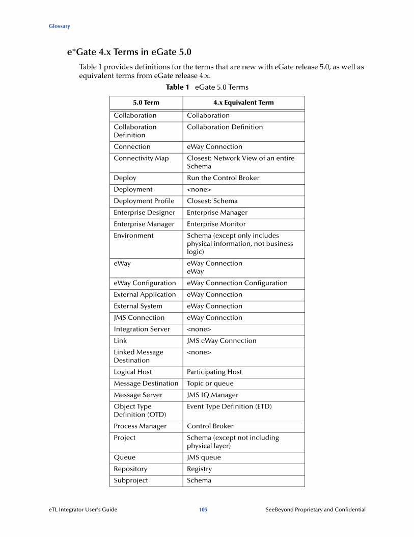
Glossary
e*Gate 4.x Terms in eGate 5.0
Table 1 provides definitions for the terms that are new with eGate release 5.0, as well as equivalent terms from eGate release 4.x.
Table 1 eGate 5.0 Terms
5.0 Term 4.x Equivalent Term
Collaboration Collaboration
Collaboration Definition
Collaboration Definition
Connection eWay Connection
Connectivity Map Closest: Network View of an entire Schema
Deploy Run the Control Broker
Deployment <none>
Deployment Profile Closest: Schema
Enterprise Designer Enterprise Manager
Enterprise Manager Enterprise Monitor
Environment Schema (except only includes physical information, not business logic)
eWay eWay ConnectioneWay
eWay Configuration eWay Connection Configuration
External Application eWay Connection
External System eWay Connection
JMS Connection eWay Connection
Integration Server <none>
Link JMS eWay Connection
Linked Message Destination
<none>
Logical Host Participating Host
Message Destination Topic or queue
Message Server JMS IQ Manager
Object Type Definition (OTD)
Event Type Definition (ETD)
Process Manager Control Broker
Project Schema (except not including physical layer)
Queue JMS queue
Repository Registry
Subproject Schema
eTL Integrator User’s Guide 105 SeeBeyond Proprietary and Confidential

Glossary
Topic JMS topic
XSLT <none>
Table 1 eGate 5.0 Terms (Continued)
5.0 Term 4.x Equivalent Term
eTL Integrator User’s Guide 106 SeeBeyond Proprietary and Confidential
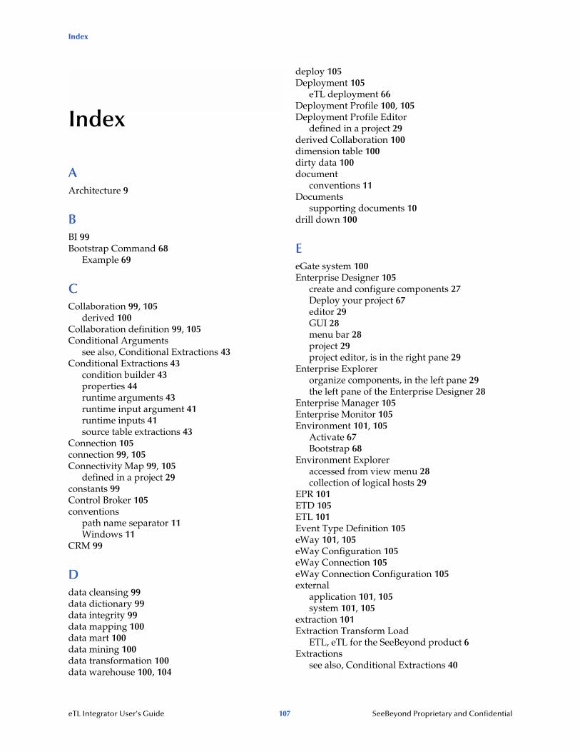
Index
Index
AArchitecture 9
BBI 99Bootstrap Command 68
Example 69
CCollaboration 99, 105
derived 100Collaboration definition 99, 105Conditional Arguments
see also, Conditional Extractions 43Conditional Extractions 43
condition builder 43properties 44runtime arguments 43runtime input argument 41runtime inputs 41source table extractions 43
Connection 105connection 99, 105Connectivity Map 99, 105
defined in a project 29constants 99Control Broker 105conventions
path name separator 11Windows 11
CRM 99
Ddata cleansing 99data dictionary 99data integrity 99data mapping 100data mart 100data mining 100data transformation 100data warehouse 100, 104
deploy 105Deployment 105
eTL deployment 66Deployment Profile 100, 105Deployment Profile Editor
defined in a project 29derived Collaboration 100dimension table 100dirty data 100document
conventions 11Documents
supporting documents 10drill down 100
EeGate system 100Enterprise Designer 105
create and configure components 27Deploy your project 67editor 29GUI 28menu bar 28project 29project editor, is in the right pane 29
Enterprise Explorerorganize components, in the left pane 29the left pane of the Enterprise Designer 28
Enterprise Manager 105Enterprise Monitor 105Environment 101, 105
Activate 67Bootstrap 68
Environment Exploreraccessed from view menu 28collection of logical hosts 29
EPR 101ETD 105ETL 101Event Type Definition 105eWay 101, 105eWay Configuration 105eWay Connection 105eWay Connection Configuration 105external
application 101, 105system 101, 105
extraction 101Extraction Transform Load
ETL, eTL for the SeeBeyond product 6Extractions
see also, Conditional Extractions 40
eTL Integrator User’s Guide 107 SeeBeyond Proprietary and Confidential

Index
Ffact table 101Flat files
see OTD, flat files 29
IICAN Suite 101Integration Server 101, 105
JJMS
connection 105e*Way Connection 105IQ Manager 105queue 105topic 106
JMS IQ Manager 101join 101
Llink 101, 105linked message destination 102, 105Logical Host 102, 105
MManagement Agent 102Menu Bar 28message
destination 102, 105server 105
metadata 102
Nnetwork view 105non-normalized data 102normalized data 102
OObject Type Definition 102, 105OLAP 102Operators and transformation tools
literal 88touppercase 88
OTD 102, 105creating a flat file 29flat file, field delimiter 35flat files, selection criteria 31
suggested record displays, based on your file structure 37
OTD Editordefined in a project 29
PParticipating Host 105Process Manager 105Project 102, 105
connect to database 52, 73create new object type definition 51, 72Deploy and activate 67Enterprise Designer window 79new eTL Collaboration 80properties 44Run bootstrap and management agent 68select database objects 74select tables using search tools 75specify OTD name 78tables and views 75using eTL with eInsight 94using with eInsight, business rules 95using with eInsight, inbound mapping for eTL 95using with eInsight, outbound mapping 97using with eInsight, validate 97
Qquery 103queue 103, 105
Rraw data 103rdbm 103Registry 105relational database 103Repository 103, 105
SSchema 105Schema Runtime Environment 103Security Server 103SQL
default type 34enter SQL directly 45validate and test 63, 92
SRE 103staging data 104subproject 104, 105
eTL Integrator User’s Guide 108 SeeBeyond Proprietary and Confidential

Index
Ttable 104topic 104, 105, 106transformation 104
VValidate and Test 63, 92
Wwarehouse 104Windows
The Bootstrap command is case sensitive on Windows 68
writing conventions 11
XXSLT 104, 106
eTL Integrator User’s Guide 109 SeeBeyond Proprietary and Confidential