ethernet/ip tm connection guide omron corporation rfid … · 2018-05-22 · there are two kinds of...
TRANSCRIPT

OMRON Corporation RFID Reader/Writer (V680S-series)
CJ Series EtherNet/IPTM Connection Guide
P626-E1-01

About Intellectual Property Rights and Trademarks Microsoft product screen shots reprinted with permission from Microsoft Corporation. Windows is a registered trademark of Microsoft Corporation in the USA and other countries. ODVA and EtherNet/IPTM are trademarks of ODVA. Company names and product names in this document are the trademarks or registered trademarks of their respective companies.

Table of Contents 1. Related Manuals .......................................................................................... 1 2. Terms and Definitions ................................................................................. 2 3. Precautions .................................................................................................. 4 4. Overview ...................................................................................................... 5 5. Applicable Devices and Device Configuration ........................................ 6
5.1. Applicable Devices .............................................................................. 6 5.2. Device Configuration ........................................................................... 7
6. EtherNet/IP Settings .................................................................................... 9 6.1. Parameters .......................................................................................... 9 6.2. Allocating the Tag Data Links ............................................................ 10
7. EtherNet/IP Connection Procedure .......................................................... 11 7.1. Work Flow ........................................................................................... 11 7.2. Setting up RFID Reader/Writer ......................................................... 13 7.3. Setting up PLC .................................................................................. 17 7.4. Setting up the Network ...................................................................... 27 7.5. Checking the EtherNet/IP Communications ...................................... 40
8. Initialization Method .................................................................................. 49 8.1. Initializing PLC ................................................................................... 49 8.2. Initializing RFID Reader/Writer .......................................................... 51
9. Appendix Setting the Tag Data Links ..................................................... 52 9.1. Tag sets of Originator Device ............................................................ 52 9.2. Setting the Connections .................................................................... 53
10. Revision History .................................................................................... 54

1.Related Manuals
1
1. Related Manuals To ensure system safety, make sure to always read and heed the information provided in all Safety Precautions and Precautions for Safe Use of manuals for each device which is used in the system.
Cat. No. Model Manual name W472 CJ2M-CPU[][]
CJ2H-CPU6[] CJ2H-CPU6□-EIP
CJ Series CJ2 CPU Unit Hardware User´s Manual
W473 CJ2M-CPU[][] CJ2H-CPU6[] CJ2H-CPU6[]-EIP
CJ Series CJ2 CPU Unit Software User's Manual
W465 CJ1W-EIP21 CJ2H-CPU6[]-EIP CJ2M-CPU3[]
EtherNet/IPTM Units Operation Manual
W446 - CX-Programmer Operation Manual 0969584-7 W4S1-05[]
W4S1-03B Switching Hub W4S1-series Users Manual
Z353 V680S-HMD63-EIP V680S-HMD64-EIP V680S-HMD66-EIP
V680S Series User’s Manual (EtherNet/IPTM) Reader/Writer

2.Terms and Definitions
2
2. Terms and Definitions
Term Explanation and Definition Node Programmable controllers and devices are connected to an EtherNet/IP
network via EtherNet/IP ports. EtherNet/IP recognizes each EtherNet/IP port connected to the network as one node. When a device with two EtherNet/IP ports is connected to the EtherNet/IP network, EtherNet/IP recognizes this device as two nodes. EtherNet/IP achieves the communications between programmable controllers or the communications between programmable controllers and devices by exchanging data between these nodes connected to the network.
Tag A minimum unit of the data that is exchanged on the EtherNet/IP network is called a tag. The tag is defined as a network variable or as a physical address, and it is allocated to the memory area of each device.
Tag set In the EtherNet/IP network, a data unit that consists of two or more tags can be exchanged. The data unit consisting of two or more tags for the data exchange is called a tag set. Up to eight tags can be configured per tag set for OMRON programmable controllers.
Tag data link In EtherNet/IP, a tag and a tag set can be exchanged cyclically between nodes without using a user program. This standard feature on EtherNet/IP is called a tag data link.
Connection A connection is used to exchange data as a unit within which data concurrency is maintained. The connection consists of tags or tag sets. Creating the concurrent tag data link between the specified nodes is called a "connection establishment". When the connection is established, the tags or tag sets that configure the connection are exchanged between the specified nodes concurrently.
Connection type There are two kinds of connection types for the tag data link connection, one is a multi-cast connection and the other is a unicast (point-to-point) connection. The multi-cast connection sends an output tag set in one packet to multiple nodes. The unicast connection separately sends one output tag set to each node. Therefore, multi-cast connections can decrease the communications load if one output tag set is sent to multiple nodes.
Originator and Target
To perform tag data links, one node requests the opening of a communications line called a "connection". The node that requests to open the connection is called an "originator", and the node that receives the request is called a "target".
Tag data link parameter
The tag data link parameter is the setting data to perform the tag data link. It includes the data to set tags, tag sets, and connections.

2.Terms and Definitions
3
EDS file A file that describes the number of I/O points for the EtherNet/IP device and the parameters that can be set via EtherNet/IP.
Operation mode (RFID Reader/Writer)
V680S-series RFID Reader/Writer has three operation modes: Run Mode, Safe Mode, and Slave Mode. ■Run Mode
An operation mode that performs in the commands from the host device.
■Safe Mode An operation mode that starts with fixed IP settings when you do not remember the IP address that is set in RFID Reader/Writer.
■Slave Mode An operation mode that performs according to instructions from the Master Reader/Writer when you use the multi-Reader/Writer functions.
Communications option (RFID Reader/Writer)
V680S-series Reader/Writer has three communications options to communicate with RF Tags: Once, Repeat, and FIFO Repeat. ■Once
The Reader/Writer communicates with RF Tags for command execution requests from the host device. When the Reader/Writer is finished communicating with an RF Tag, it returns the communications results to the host device and waits for another command.
■Repeat When the Reader/Writer receives a command execution request from the host device, it automatically detects RF Tags in the communications field and communicates with them. This process is repeated until the execution request is cleared. Communications are not performed for RF Tags that have returned communications results to the host device until RF Tags leave the communications field.
■FIFO Repeat When the Reader/Writer receives a command execution request from the host device, it automatically detects RF Tags in the communications field and communicates with them. After successfully communicating with an RF Tag once, operation for that RF Tag is stopped. This process is repeated until the execution request is cleared. Communications are not performed for RF Tags that have returned communications results to the host device until the RF Tags leave the communications field.

3.Precautions
4
3. Precautions (1) Understand the specifications of devices which are used in the system. Allow some
margin for ratings and performance. Provide safety measures, such as installing safety circuit, in order to ensure safety and minimize risks of abnormal occurrence.
(2) To ensure system safety, make sure to always read and heed the information provided in all Safety Precautions and Precautions for Safe Use of manuals for each device which is used in the system.
(3) The user is encouraged to confirm the standards and regulations that the system must conform to.
(4) It is prohibited to copy, to reproduce, and to distribute a part or the whole of this document without the permission of OMRON Corporation.
(5) The information contained in this document is current as of June 2015. It is subject to change without notice for improvement.
The following notations are used in this document.
Indicates a potentially hazardous situation which, if not avoided, may result in minor or moderate injury or property damage.
Precautions for Correct Use
Precautions on what to do and what not to do to ensure proper operation and performance.
Additional Information Additional information to read as required. This information is provided to increase understanding or make operation easier.
Symbol
The triangle symbol indicates precautions (including warnings). The specific operation is shown in the triangle and explained in text. This example indicates a general precaution.

4.Overview
5
4. Overview This document describes the procedure for connecting V680S-series RFID Reader/Writer (hereinafter referred to as RFID Reader/Writer) of OMRON Corporation (hereinafter referred to as OMRON) to CJ-series Programmable Controller + Ethernet/IP Unit (hereinafter referred to as PLC) via EtherNet/IP, and the procedure to check their connection. Refer to Section 6. EtherNet/IP Settings and Section 7. EtherNet/IP Connection Procedure to understand the setting method and key points to perform the tag data links for EtherNet/IP. In this document, CJ-series EtherNet/IP Unit and the built-in EtherNet/IP port of CJ-series CJ2 CPU Unit are collectively called as "EtherNet/IP Unit".

5.Applicable Devices and Device Configuration
6
5. Applicable Devices and Device Configuration
5.1. Applicable Devices The applicable devices are as follows: Manufacturer Name Model
OMRON CJ2 CPU Unit CJ2[]-CPU[][] OMRON EtherNet/IP Unit CJ1W-EIP21
CJ2H-CPU6[]-EIP CJ2M-CPU3[]
OMRON RFID Reader/Writer V680S-HMD63-EIP V680S-HMD64-EIP V680S-HMD66-EIP
Precautions for Correct Use
As applicable devices above, the devices with the models and versions listed in 5.2. Device Configuration are actually used in this document to describe the procedure for connecting devices and checking the connection. You cannot use devices with versions lower than the versions listed in 5.2. To use the above devices with models not listed in 5.2. or versions higher than those listed in 5.2., check the differences in the specifications by referring to the manuals before operating the devices.
Additional Information This document describes the procedure to establish the network connection. It does not provide information on operation, installation or wiring method which is not related to the connection procedure. It also does not describe the functionality or operation of the devices. Refer to the manuals or contact your OMRON representative.
Additional Information For information on applicable RF Tags, refer to the V680S Series User's Manual (EtherNet/IPTM) Reader/Writer (Cat. No. Z353).

5.Applicable Devices and Device Configuration
7
5.2. Device Configuration The hardware components to reproduce the connection procedure of this document are as follows:
Manufacturer Name Model Version OMRON CPU Unit
(Built-in EtherNet/IP port) CJ2M-CPU32 Ver.2.0
(Ver.2.12) OMRON Power Supply Unit CJ1W-PA202 OMRON Switching hub W4S1-05C Ver.1.00 - 24 VDC power supply
(For Switching hub) -
OMRON CX-One CXONE-AL[][]C-V4 /AL[][]D-V4
Ver.4.[][]
OMRON CX-Programmer (Included in CX-One) Ver.9.53 OMRON Network Configurator (Included in CX-One) Ver.3.58 - Personal computer
(OS: Windows 7) -
- Web browser - - USB cable
(USB 2.0 type B connector) -
- LAN cable (STP (shielded, twisted-pair) cable of Ethernet category 5 or higher)
-
OMRON RFID Reader/Writer V680S-HMD63-EIP Ver.3.00 OMRON RF Tag V680S-D2KF67 OMRON LAN cable
(With M12/RJ45 connector) (RFID Reader/Writer)
XS5W-series
OMRON Power supply cable (With M12 connector) (For RFID Reader/Writer)
XS2F-series
- 24 VDC power supply (For RFID Reader/Writer)
-
Precautions for Correct Use
Update CX-Programmer and Network Configurator to the version specified in this clause or higher version. If you use a version lower than the one specified in this clause, the procedures described in Section 7. and subsequent sections may not be applicable. In that case, use the equivalent procedures described in this document by referring the CX-Programmer Operation Manual (Cat. No. W446) and Network Configurator Online Help.
CJ2M-CPU32 (Built-in EtherNet/IP port)
USB cable
LAN cable W4S1-05C V680S-D2KF67
Personal computer (CX-One, Web browser installed, OS: Windows 7)
24 VDC power supply 24 VDC power supply
V680S-HMD63-EIP
LAN cable Power supply cable
LAN cable

5.Applicable Devices and Device Configuration
8
Additional Information For information on a web browser to use, refer to Section 6. Browser Interface of the V680S Series User's Manual (EtherNet/IPTM) Reader/Writer (Cat. No. Z353).
Additional Information For specifications of 24 VDC power supply available for Switching hub, refer to the Switching Hub W4S1-series Users Manual (Cat. No. 0969584-7).
Additional Information For specifications of 24 VDC power supply available for RFID Reader/Writer, refer to the V680S Series User's Manual (EtherNet/IPTM) Reader/Writer (Cat. No. Z353).
Additional Information The system configuration in this document uses USB for the connection between Personal computer and PLC. For information on how to install USB driver, refer to A-5 Installing the USB Driver of the CJ-series CJ2 CPU Unit Hardware User's Manual (Cat. No. W472).

6.EtherNet/IP Settings
9
6. EtherNet/IP Settings This section describes specifications of parameters and the tag data link allocation that are set in this document. This document explains the settings and the connection procedures in a case where a data size to use for tag data links is 40 bytes. However, you can also select other bytes: 264, 520, and 1032 as a data size. For use of other data sizes, refer to Section 9. Appendix Setting the Tag Data Links. Hereinafter, RFID Reader/Writer is referred to as "Destination Device" in some descriptions.
6.1. Parameters The parameter settings that are set in this document are as follows:
6.1.1. Communication Settings of Personal Computer RFID Reader/Writer is set by using the Ethernet communications in a web browser of Personal computer. The parameters for Personal computer and RFID Reader/Writer required for Ethernet communications are shown below.
Item Personal computer for settings RFID Reader/Writer IP address 192.168.1.100 192.168.1.200 (default) Subnet mask 255.255.255.0 255.255.255.0 (default)
6.1.2. EtherNet/IP Communications Settings The parameters required for connecting PLC and RFID Reader/Writer via EtherNet/IP are shown below.
Item PLC (node 1) RFID Reader/Writer (node 2). Unit number 0 - Node address 1 2 IP address 192.168.250.1 192.168.250.2 Subnet mask 255.255.255.0 255.255.255.0 Communications option - Once (default)
Additional Information For information on the communications options for RFID Reader/Writer, refer to the V680S Series User's Manual (EtherNet/IPTM) Reader/Writer (Cat. No. Z353).

6.EtherNet/IP Settings
10
6.2. Allocating the Tag Data Links The following provides the detailed settings of the tag data link allocation for RFID Reader/Writer. Output area Input area
D10000
D10019
(PLC to RFID Reader/Writer) 40 bytes
D10100
D10119
(RFID Reader/Writer to PLC) 40 bytes
■Details on output area
Address Bit 15 14 13 12 11 10 9 8 7 6 5 4 3 2 1 0
D10000 Resv Resv Resv Resv Resv Resv Resv Resv Resv Resv Resv Resv Resv Resv Resv EXE
D10001 Command Code D10002 Command Parameter 1 D10003 Command Parameter 2 D10004
: D10019
Command Data
■Details on input area
Address Bit 15 14 13 12 11 10 9 8 7 6 5 4 3 2 1 0
D10100 Resv Resv Resv Resv Resv Resv Resv RF_WAR
SYS_ERR
RF_ERR
CMD_ERR FRIC ERR NOR
M BUSY READY
D10101 Error Code D10102 Response Information 1 D10103 Response Information 2 D10104
: D10119
Response Data
Additional Information For the allocation of tag data links of RFID Reader/Writer, refer to Memory Assignments in EtherNet/IP Communications Protocol in Section 5. Host Communications Specifications of the V680S Series User’s Manual (EtherNet/IPTM) Reader/Writer (Cat. No. Z353).

7.EtherNet/IP Connection Procedure
11
7. EtherNet/IP Connection Procedure This section describes the procedure for connecting RFID Reader/Writer and PLC on the EtherNet/IP network. This document provides the explanation of the procedure for setting up PLC and RFID Reader/Writer based on the factory default setting. For the initialization, refer to Section 8. Initialization Method.
7.1. Work Flow Take the following steps to set the tag data links for EtherNet/IP.
7.2. Setting up RFID Reader/Writer Set up RFID Reader/Writer. ↓
7.2.1. Parameter Settings Set the IP address of RFID Reader/Writer.
↓
7.3. Setting up PLC Set up PLC.
↓
7.3.1. Hardware Settings Set the hardware switches on EtherNet/IP Unit.
↓
7.3.2. Starting CX-Programmer and Connecting Online with PLC
Start CX-Programmer and connect online with PLC.
↓
7.3.3. Creating the I/O Table and setting the IP Addresses
Create the I/O table and set the IP address of PLC.
↓
7.4. Setting up the Network Set the tag data links for EtherNet/IP.
↓
7.4.1. Starting Network Configurator and Connecting Online with PLC
Start Network Configurator and connect online with PLC.
↓
7.4.2. Uploading the Network Configuration
Upload the network configuration.
↓
7.4.3. Setting the Tags Register tags of the send and receive areas.
↓
7.4.4. Setting the Connections Associate tags of the target device with tags of the originator device.
↓
7.4.5. Transferring the Tag Data Link Parameters
Transfer the set tag data link parameters to PLC.
↓

7.EtherNet/IP Connection Procedure
12
7.5. Checking the EtherNet/IP Communications
Check that EtherNet/IP tag data links are operated normally.
↓
7.5.1. Checking the Connection Status Check the connection status of EtherNet/IP.
↓
7.5.2. Checking the Sent and Received Data
Check that the correct data are sent and received.
7.EtherNet/IP Connection Procedure
13
7.2. Setting up RFID Reader/Writer Set up RFID Reader/Writer.
7.2.1. Parameter Settings Set the IP address of RFID Reader/Writer. Set the IP address of Personal computer to 192.168.1.100. A web browser is used in the parameter settings for RFID Reader/Writer. Check if you can use a web browser on Personal computer.
Precautions for Correct Use
Set the parameters for RFID Reader/Writer by using the Ethernet communications of Personal computer. Note that you may need to change the settings of Personal computer depending on the status of Personal computer.
Precautions for Correct Use
If RFID Reader/Writer was changed from the factory default setting, make sure to start in Safe Mode. The IP address is always 192.168.1.200. For information on starting in Safe Mode, refer to Connector in Section 2. Names and Functions of Components of the V680S Series User's Manual (EtherNet/IPTM) Reader/Writer (Cat. No. Z353).
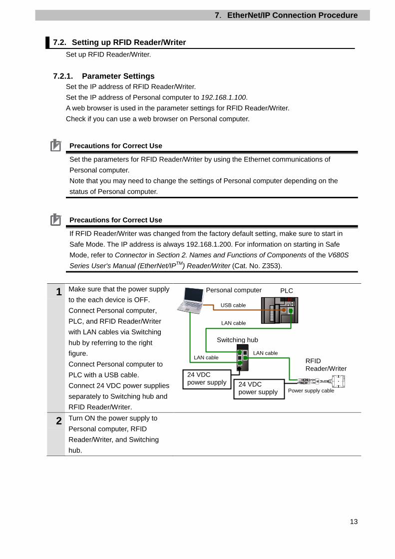
1 Make sure that the power supply to the each device is OFF. Connect Personal computer, PLC, and RFID Reader/Writer with LAN cables via Switching hub by referring to the right figure. Connect Personal computer to PLC with a USB cable. Connect 24 VDC power supplies separately to Switching hub and RFID Reader/Writer.
2 Turn ON the power supply to Personal computer, RFID Reader/Writer, and Switching hub.
24 VDC power supply
LAN cable
Switching hub
24 VDC power supply
Personal computer
RFID Reader/Writer
LAN cable
Power supply cable
PLC
USB cable
LAN cable

7.EtherNet/IP Connection Procedure
14
3 Set the IP address of Personal computer to 192.168.1.100. *Take the following procedure to change the IP address of Personal computer.
(1)Start Personal computer and
login as administrator. Then open Control Panel from the start menu, select Network and Internet - Network and Sharing Center - Change Adapter Settings, and double-click Local Area Connection.
*The operating procedure may differ depending on the environment of Personal computer.
(2)The Local Area Connection
Status Dialog Box is displayed. Click Properties.
(3)The Local Area Connection
Properties Dialog Box is displayed. Select Internet Protocol Version 4 (TCP-IPv4), and click Properties.
*The display differs depending on the configuration of Personal computer.
(4)The Internet Protocol Version
4 (TCP/IPv4) Properties Dialog Box is displayed. Select Use the following IP address, enter 192.168.1.100 as the IP address and 255.255.255.0 as the subnet mask, and click OK.
(5)Close all dialog boxes by
clicking Close or OK.
Screen of (2)
Screen of (3)
Screen of (4)

7.EtherNet/IP Connection Procedure
15
4 Start a web browser on Personal computer and type http://192.168.1.200/ in the address bar. The setting window for V680S RFID Reader/Writer is displayed. *You can select a display language from the pull-down list which is displayed on the upper right of the browser operation window. In this document, the default language ''English'' is used.
Click Network settings.
5 Network settings is displayed. Set the following values and click Set. ・IP address: 192.168.250.2 ・Subnet mask: 255.255.255.0
6 A confirmation dialog box is displayed as shown on the right. Check the contents and click Yes.
7 A confirmation dialog box is displayed as shown on the right. Check the contents and click OK.

7.EtherNet/IP Connection Procedure
16
8 Click Communication settings.
9 RF Tag communication settings is displayed. Check that Once is selected for RF Tag communications option. *If RF Tag communications option is not Once, select Once from the pull-down list, and click Set. A dialog box for the setting change is displayed. Check the contents and click OK.
*For details on RF Tag communications option, refer to Communications Options in RF Tag Communications in Functions in Section 2. Names and Functions of Components of the V680S Series User's Manual (EtherNet/IPTM) Reader/Writer (Cat. No. Z353).
10 Close the web browser.
11 Cycle the power supply to RFID Reader/Writer. *The settings become effective by cycling the power supply.

7.EtherNet/IP Connection Procedure
17
7.3. Setting up PLC Set up PLC.
7.3.1. Hardware Settings Set the hardware switches on EtherNet/IP Unit.
Precautions for Correct Use
Make sure that the power supply to PLC is OFF when you perform the setting up.
1 Make sure that the power supply to PLC is OFF. *If the power supply is turned ON, settings may not be applicable as described in the following procedure.
2 Check the positions of hardware switches on the front of EtherNet/IP Unit by referring to the right figure.
3 Set the unit number setting switch to 0.
The unit number is used to identify individual CPU Bus Units when more than one CPU Bus Unit is mounted to the same PLC. Use a small screwdriver to make the setting, taking care not to damage the rotary switch. The unit number is factory-set to 0.
4 Set the node address setting switches to the following default settings.
NODE No.x161: 0 NODE No.x160: 1
*Set the IP address to 192.168.250.1.
*By default, the first to third octets of the local IP address are fixed to 192.168.250. The fourth octet is the values that are set with the node address setting switches.
With the FINS communications service, when there are multiple EtherNet/IP Units connected to the Ethernet network, the EtherNet/IP Units are identified by node addresses. Use the node address switches to set the node address between 01 and FE hexadecimal (1 to 254 decimal).Do not set a number that has already been set for another node on the same network.
The left switch sets the sixteens digit (most significant digit) and the right switch sets the ones digit (least significant digit).The node address is factory-set to 01. Default IP address = 192.168.250.node address With the factory-default node address setting of 01, the default IP address is 192.168.250.1.

7.EtherNet/IP Connection Procedure
18
5 Turn ON the power supply to PLC.
6 The set IP address is displayed on the seven-segment LED indicators. Afterwards, the last digit of the IP address is displayed in hexadecimal during normal operation.

7.EtherNet/IP Connection Procedure
19
7.3.2. Starting CX-Programmer and Connecting Online with PLC Start CX-Programmer and connect online with PLC. Install CX-One and a USB driver in Personal computer beforehand.
1 Start CX-Programmer. *If a confirmation dialog for an access right is displayed at start, execute a selection to start.
2 CX-Programmer starts.
3 Select Auto Online - Direct Online from the PLC Menu.
4 The Direct Online Dialog Box is displayed. Select USB connection for Connection Type. Click Connect.

7.EtherNet/IP Connection Procedure
20
5 The dialog box on the right is displayed. Check the contents and click No.
6 The dialog box on the right is displayed, and CX-Programmer and PLC are automatically connected.
7 Check that CX-Programmer and PLC are normally connected online.
*The icon is pressed down during online connection.
Additional Information If an online connection cannot be made to PLC, check the cable connection. Or, return to step 1, check the settings and repeat each step. For details, refer to Connecting Directly to a CJ2 CPU Unit Using a USB Cable in Chapter 3 Communications in PART 3: CX-Server Runtime of the CX-Programmer Operation Manual (Cat. No. W446).
Additional Information The dialog boxes explained in the following procedures may not be displayed depending on the environmental setting of CX-Programmer. For details on the environmental setting, refer to Options and Preferences in Chapter 3 Project Reference in PART 1: CX-Programmer of the CX-Programmer Operation Manual (Cat. No. W446). This document explains the setting procedure when Confirm all operations affecting PLC is selected.

7.EtherNet/IP Connection Procedure
21
7.3.3. Creating the I/O Table and setting the IP Addresses Create the I/O table and set the IP address of PLC.
1 If the operating mode of PLC is Run Mode or Monitor Mode, change it to Program Mode by following the steps below. (1)Select Operating Mode -
Program from the PLC Menu of CX-Programmer.
(2)A confirmation dialog box on
the right is displayed. Check that there is no problem and click Yes.
*Refer to Additional Information on the previous page for the settings concerning the dialog display.
(3)Check that Stop/Program
Mode is displayed on the right of the PLC model in the project workspace of CX-Programmer.
2 Select Edit - I/O Table and Unit Setup from the PLC Menu of CX-Programmer. The PLC IO Table Window is displayed.

7.EtherNet/IP Connection Procedure
22
Precautions for Correct Use
PLC will be reset after creating and transferring the I/O table in step 3 and subsequent steps. Always confirm safety before creating and transferring the I/O table.
3 Select Create from the Options Menu of the PLC IO Table Window. A confirmation dialog box on the right is displayed. Check that there is no problem and click Yes. A confirmation dialog box on the right is displayed. Check that there is no problem and click Yes.

7.EtherNet/IP Connection Procedure
23
4 The Transfer from PLC Dialog Box is displayed. Select I/O Table and SIO Unit Parameters, and click Transfer. When the transfer is completed, the Transfer Results Dialog Box is displayed. Check that the transfer was normally executed by referring to the message in the dialog box. When the I/O table is created normally, the dialog box displays as follows: Transfer Success: 1 Unit Transfer Unsuccessful: 0 Unit Click OK.

7.EtherNet/IP Connection Procedure
24
5 On the PLC IO Table Window, click + to the left of Built-in Port/Inner Board to display CJ2M-EIP21. *The right figure displays CPU Unit (Built-in EtherNet/IP port) specified in 5.2. Device Configuration. If you use other applicable EtherNet/IP Units, the display position and name are different from this figure.
Right-click CJ2M-EIP21 and select Unit Setup.
6 The Edit Parameters Dialog Box is displayed. Select the TCP/IP Tab. Make the following settings in the IP Address Field. ・Use the following address:
Select ・IP address: 192.168.250.1 ・Subnet mask: 255.255.255.0
Click Transfer[PC to Unit].

7.EtherNet/IP Connection Procedure
25
7 The dialog box on the right is displayed. Check that there is no problem and click Yes. Check that a message stating "Transfer successful" is displayed, and click Close.
8 A confirmation dialog box is displayed. Check the contents and click Yes. When the Unit is restarted, the dialog box on the right is displayed. Check the contents and click OK.
7.EtherNet/IP Connection Procedure
26
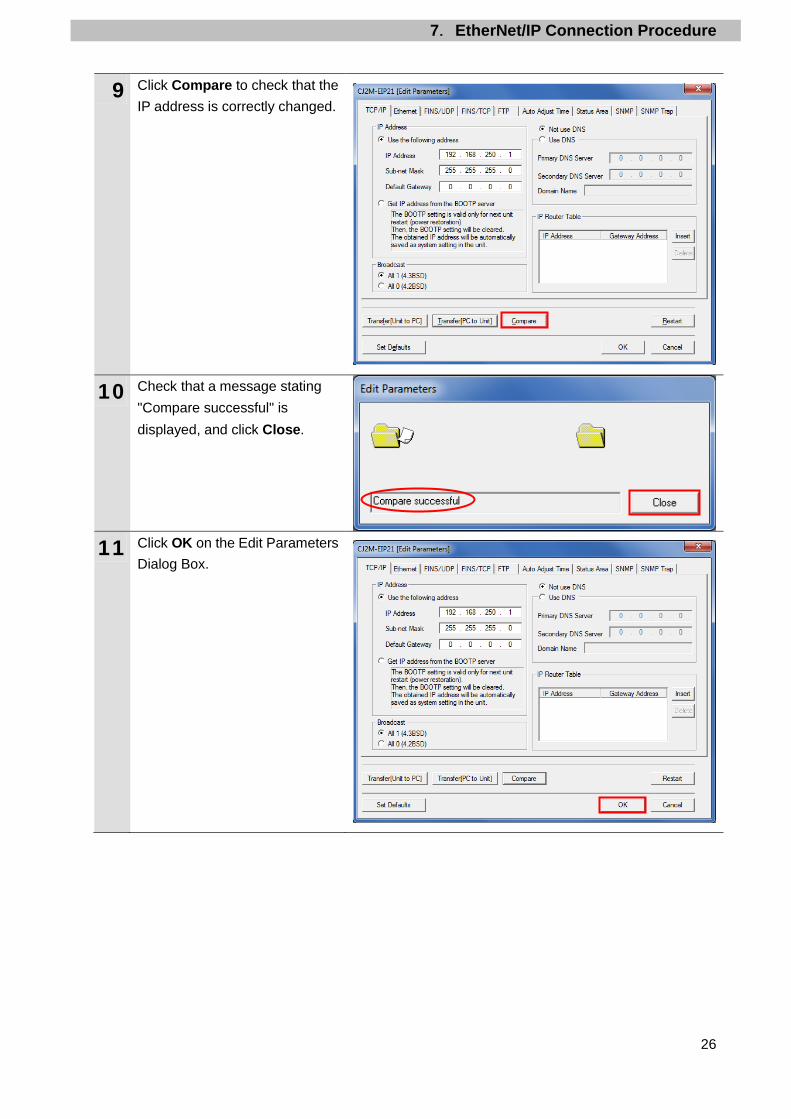
9 Click Compare to check that the IP address is correctly changed.
10 Check that a message stating "Compare successful" is displayed, and click Close.
11 Click OK on the Edit Parameters Dialog Box.

7.EtherNet/IP Connection Procedure
27
7.4. Setting up the Network Set the tag data links for EtherNet/IP.
7.4.1. Starting Network Configurator and Connecting Online with PLC Start Network Configurator and connect online with PLC.
1 Right-click CJ2M-EIP21 on the PLC IO Table Window, and select Start Special Application - Start with Settings Inherited. The Select Special Application Dialog Box is displayed. Select Network Configurator and click OK.
2 Network Configurator starts.

7.EtherNet/IP Connection Procedure
28
Precautions for Correct Use Check that LAN cables are connected before performing the following procedure. If they are not connected, turn OFF the power supply to each device, and then connect LAN cables.
3 Select Select Interface - CJ2 USB/Serial Port from the Option Menu.
4 Select Connect from the Network Menu.
5 The Setup Interface Dialog Box is displayed, Check that the following settings are made.
Port Type: USB Port: OMR0 Baud Rate: 115200 Bit/s
Click OK.
6 The Select Connect Network Port Dialog Box is displayed. Select Back Plane - CJ2M-EIP21 - TCP:2. Click OK.

7.EtherNet/IP Connection Procedure
29
7 The Select Connected Network Dialog Box is displayed. Check the contents and click OK.
8 When an online connection is established normally, the color of the icon on the figure changes to blue.
Additional Information If an online connection cannot be made to PLC, check the cable connection. Or, return to step 3, check the settings and repeat each step. For details, refer to 6-2-9. Connecting the Network Configurator to the Network in Section 6. Tag Data Link Functions of the EtherNet/IPTM Units Operation Manual (Cat. No. W465).

7.EtherNet/IP Connection Procedure
30
7.4.2. Uploading the Network Configuration Upload the network configuration.
1 Select Upload from the Network Menu to upload the device information on the network.
2 A confirmation dialog box on the right is displayed. Check that there is no problem and click Yes.
3 The Target Device Dialog Box is displayed. Select 192.168.250.1 and 192.168.250.2. Click OK. *If 192.168.250.1 and 192.168.250.2 are not displayed on the dialog box, click Add to add the addresses.
*The displayed addresses depend on the status of Network Configurator.
4 The device parameters are uploaded. When uploading is completed, the dialog box on the right is displayed. Check the contents and click OK.

7.EtherNet/IP Connection Procedure
31
5 After uploading, check that the IP addresses of uploaded nodes are updated on the Network Configuration Pane as follows:
IP Address: of node 1: 192.168.250.1
IP Address of node 2: 192.168.250.2

7.EtherNet/IP Connection Procedure
32
7.4.3. Setting the Tags Register tags of the send and receive areas. The following explains receive and send settings of the target device in order.
1 On the Network Configuration Pane of Network Configurator, right-click the node 1 device and select Parameter - Edit.
2 The Edit Device Parameters Dialog Box is displayed. Select the Tag Sets Tab.
3 The data on the Tag Sets Tab is displayed. Select the In-Consume Tab and click Edit Tags.

7.EtherNet/IP Connection Procedure
33
4 The Edit Tags Dialog Box is displayed. Select the In - Consume Tab and click New. Here, register an area where node 1 receives data from node 2.
5 The Edit Tag Dialog Box is displayed. Enter the following values in the parameters. Name: D10100
(Start address of the input data to node 1)
Size: 40 (Bytes) After entering, click Regist.
6 The Edit Tag Dialog Box is displayed again. Click Close.

7.EtherNet/IP Connection Procedure
34
7 Select the Out - Produce Tab, and then click New. Here, register the data sent from node 1 to node 2.
8 The Edit Tag Dialog Box is displayed. Enter the following values in the parameters. Name: D10000 (Start address of the output data from node 1) Size: 40 (Bytes)
After entering, click Regist.
9 The Edit Tag Dialog Box is displayed again. Click Close.

7.EtherNet/IP Connection Procedure
35
10 When you finish the registration, click OK on the Edit Tags Dialog Box.
11 A confirmation dialog box on the right is displayed. Check that there is no problem and click Yes.
12 The Edit Device Parameters Dialog Box is displayed again. Select the Connections Tab.

7.EtherNet/IP Connection Procedure
36
7.4.4. Setting the Connections Associate tags of the target device (that receives the open request) with tags of the originator device (that requests opening).
1 Select 192.168.250.2 in the Unregister Device List Field. Click the Down Arrow Button that is shown in the dialog box.
2 192.168.250.2 is registered in the Register Device List Field. Select 192.168.250.2 and click New.

7.EtherNet/IP Connection Procedure
37
3 The Edit Connection Dialog Box is displayed. Select Consume Data From/Produce Data To : 40 from the Connection I/O Type pull-down list. Set the values listed in the following table in the Originator Device and the Target Device Fields.
■Connection configuration settings
Connection configuration Set value Connection I/O Type Consume Data From /
Produce Data To :40 Originator Device Input Tag Set D10100-[40Byte]
Connection Type Point to Point connection Output Tag Set D10000-[40Byte] Connection Type Point to Point connection
Target Device Output Tag Set Input_110-[40Byte] Input Tag Set Output_100-[40Byte]
4 Check that the settings are correct and click Regist.
5 The Edit Connection Dialog Box is displayed again. Click Close.

7.EtherNet/IP Connection Procedure
38
6 The Edit Device Parameters Dialog Box is displayed again. Click OK.
7 When the connection setting is completed, the registered node address is displayed under the device icon of node 2 on the Network Configuration Pane.

7.EtherNet/IP Connection Procedure
39
7.4.5. Transferring the Tag Data Link Parameters Transfer the set tag data link parameters to PLC.
1 Right-click the device icon of node 1 on the Network Configuration Pane and select Parameter - Download.
2 A confirmation dialog box on the right is displayed. Check that there is no problem and click Yes.
3 The tag data link parameters are downloaded from Network Configurator to PLC.
4 The dialog box on the right is displayed. Check the contents and click OK.

7.EtherNet/IP Connection Procedure
40
7.5. Checking the EtherNet/IP Communications Check that EtherNet/IP tag data links are operated normally.
7.5.1. Checking the Connection Status Check the connection status of EtherNet/IP.
1 Check with LED indicators of PLC (EtherNet/IP Unit) that the EtherNet/IP tag data links are operated normally. LED indicators in normal status are as follows:
MS: Green lit NS: Green lit COMM: Yellow lit 100M or 10M: Yellow lit
2 Check LED indicators for RFID Reader/Writer. LED indicators in normal status are as follows:
RUN: Green lit LINK/ACT: Green flashing (Flashing while packets are being sent and received)
3 In the status information on the Monitor Device Window of Network Configurator, check that the tag data links are normally in operation. Right-click the device icon of node 1 on the Network Configuration Pane, and select Monitor.

7.EtherNet/IP Connection Procedure
41
4 The dialog box on the right displays the Status 1 Tab Page on the Monitor Device Dialog Box. When the same check boxes are selected as shown on the right, the tag data links are normally in operation. Click Close.
5 Select Disconnect from the Network Menu to go offline.
6 The color of the icon on the figure changes from blue to gray.
7 Select Exit from the File Menu to exit Network Configurator.
Number: Node number Blue: Connection normal

7.EtherNet/IP Connection Procedure
42
7.5.2. Checking the Sent and Received Data Check that the correct data are sent and received. In this document, sent and received data are checked in the following steps by executing READ DATA and WRITE DATA commands for RF Tag address 0000 hex..
No. Description Command Step No. in the
procedure 1 Reading the data from an RF Tag READ DATA Steps 9 to 15 2 Writing the data to the memory of the RF Tag WRITE DATA Steps 16 to 19 3 Checking a result of the write data No.2 READ DATA Steps 20 to 23
If the PLC memory is changed by malfunction during monitoring power flow and present value status in the Ladder Section window or monitoring present values in the Watch window, the devices connected to Output Units may malfunction, regardless of the operating mode of CPU Unit. Confirm safety sufficiently before monitoring power flow and present value status in the Ladder Section window or before monitoring present values in the Watch window.
Additional Information For details on commands available in RFID Reader/Writer, refer to V680S Command Details in Section 5. Host Communications Specifications of the V680S Series User's Manual (EtherNet/IPTM) Reader/Writer (Cat. No. Z353).
1 Check that PLC is in Stop/Program Mode. *If PLC is not in Stop/Program Mode, change to Stop/Program Mode by referring to step 1 of 7.3.3. Creating the I/O Table and setting the IP Addresses.

7.EtherNet/IP Connection Procedure
43
2 Select Edit - Memory from the PLC Menu.
3 The PLC Memory Window is displayed. Double-click D from the list in the PLC Memory Window.
4 Select Display - Hexadecimal from the View Menu.
5 Select Monitor from the Online Menu.

7.EtherNet/IP Connection Procedure
44
6 The Monitor Memory Areas Dialog Box is displayed. Check that D is selected, and click Monitor.
7 Enter 10000 in the Start Address Field of the D Window. Check that the start address changes to D10000.
8 Place RF Tag over the antenna (data reading part) of RFID Reader/Writer as shown on the right. *The distance between RFID Reader/Writer and RF Tag differs depending on the type of RF Tag used and the installation environment of RFID Reader/Writer. Refer to Communications Range Specifications under Data Characteristics in Section 8. Appendices of the V680S Series User's Manual (EtherNet/IPTM) Reader/Writer (Cat. No. Z353) for details.
9 In steps 9 to 15, read the data from RF Tag address 0000 hex. Check that D10000 shows 0000.

7.EtherNet/IP Connection Procedure
45
10 Select D10001 and click SetValue. The Set Value: Hexadecimal Dialog Box is displayed.
11 Enter 0002 (READ DATA command) in the Value Field. Click OK. The value of D10001 changes to 0002. *The following steps are also performed in the same way as steps 10 to 11,
12 Enter 0000 (first address to read) in D10002 and 0001 (number of WORDs to read) in D10003.
13 Enter 0001 in D10000. READ DATA command is executed by changing the bit 0 of D10000 from 0 to 1.

7.EtherNet/IP Connection Procedure
46
14 The execution results are stored in D10100 to D10104. ・D10100: 0006
(BUSY (bit 1): The bit for Command Execution Active is ON. NORM (bit 2): The bit for Command Completion is ON.)
・D10101: 0000 (Error code: Normal end)
・D10102: 0000 (Device information: Not used at normal end)
・D10103: 0000 (Results of Communication Diagnostic: Normal)
・D10104: 1234 (Read data from RF Tag)
*In this document, the value of RF Tag address 0000 hex is 1234. However, it differs depending on RF Tag used.
15 Enter 0000 in D10000 to return the bit 0 of D10000 to 0.
16 In steps 16 to 19, write the read data to RF Tag memory address 0000 hex. *In this document, 5678 is written. Enter 0003 (WRITE DATA command) in D10001, 0000 (first address to write) in D10002, 0001 (number of WORDs to write) in D10003, and 5678 (write data) in D10004.
17 Enter 0001 in D10000. WRITE DATA command is executed by changing the bit 0 of D10000 from 0 to 1.

7.EtherNet/IP Connection Procedure
47
18 The execution results are stored in D10100 to D10103. ・D10100: 0006
(BUSY (bit 1): The bit for Command Execution Active is ON. NORM (bit 2): The bit for Command Completion is ON.)
・D10101: 0000 (Error code: Normal end)
・D10102: 0000 (Device information: Not used at normal end)
・D10103: 0000 (Results of Communication Diagnostic: Normal)
*D10104 is not used for WRITE DATA command.
19 Enter 0000 in D10000 to return the bit 0 of D10000 to 0.
20 In steps 20 to 23, check that the correct data were written to RF Tag memory address 0000 hex. Enter 0002 (READ DATA command) in D10001, 0000 (first address to read) in D10002, 0001 (number of WORDs to write) in D10003. * D10004 is not used for READ DATA command.
21 Enter 0001 in D10000. READ DATA command is executed by changing the bit 0 of D10000 from 0 to 1.

7.EtherNet/IP Connection Procedure
48
22 The execution results are stored in D10100 to D10104. ・D10100: 0006
(BUSY (bit 1): The bit for Command Execution Active is ON. NORM (bit 2): The bit for Command Completion is ON.)
・D10101: 0000 (Error code: Normal end)
・D10102: 0000 (Device information: Not used at normal end)
・D10103: 0000 (Results of Communication Diagnostic: Normal)
・D10104: 5678 (Read data from RF Tag)
You can see that the correct data are written in RF Tag memory address 0000 hex.
23 Enter 0000 in D10000 to return the bit 0 of D10000 to 0.

8.Initialization Method
49
8. Initialization Method This document provides the explanation of the setting procedure based on the factory default setting. Some settings may not be applicable as described in this document unless you use the devices with the factory default setting.
8.1. Initializing PLC To initialize the settings of PLC, it is necessary to initialize CPU Unit and EtherNet/IP Unit. Change PLC to PROGRAM mode before the initialization.
8.1.1. EtherNet/IP Unit (1)Select Edit - I/O Table and Unit Setup from the PLC Menu of CX-Programmer.
Right-click EtherNet/IP Unit on the PLC IO Table Window and select Unit Setup from the menu.
(2)Click Restart on the Edit Parameters Dialog Box.

8.Initialization Method
50
(3)An execution confirmation dialog box is displayed. Check that there is no problem, and click
Yes. Next, the Restart Unit Dialog Box is displayed. Select Return to out-of-box configuration, and then emulate cycling power, and click OK. A dialog box indicating the execution is completed is displayed. Check the contents and click OK.
8.1.2. CPU Unit To initialize the settings of CPU Unit, select Clear All Memory Areas from the PLC Menu of CX-Programmer. The Confirm All Memory Area Clear Dialog Box is displayed. Select Initialize and click OK.

8.Initialization Method
51
8.2. Initializing RFID Reader/Writer For the initialization of RFID Reader/Writer, refer to Initializing the Settings in Configuration in Operation Interface in Section 6. Browser Interface of the V680S Series User's Manual (EtherNet/IPTM) Reader/Writer (Cat. No. Z353).

9.Appendix Setting the Tag Data Links
52
9. Appendix Setting the Tag Data Links This section explains the settings for the change of data size to use for the tag data links. You can choose the data size from the following four sizes.
Data size Data size that can be read or written for an RF Tag in one operation
(Maximum) 40 bytes 32 bytes 264 bytes 256 bytes 520 bytes 512 bytes
1032 bytes* 1024 bytes *40 bytes is the maximum data size to perform the tag data links by using the Built-in EtherNet/IP port on CJ2M-series CPU Unit, which means that you can use the data size up to 40 bytes. If you use more than 264 bytes, either installing CJ-series EtherNet/IP Unit or using CJ2H-series CPU Unit is required.
9.1. Tag sets of Originator Device
Set tags in the send and receive areas, and register tag sets of the originator device (PLC). Set a data size to use for the tag data links in Size which is marked with a red square. The following screenshots are examples of settings for 264 bytes data size. For settings, refer to 7.4.3. Setting the Tags. ■Input tag set: D10100 - [264Byte] ■Output tag set: D10000 - [264Byte]

9.Appendix Setting the Tag Data Links
53
9.2. Setting the Connections Associate tags of the target device (that receives the open request) with tags of the originator device (that requests opening). The following screenshot is an example of settings for 264 bytes data size. For settings, refer to 7.4.4. Setting the Connections.
■Setting the tag sets of originator device (PLC) registered in 9.1. Tag sets of Originator Device
■Settng the connection I/O types and tag sets of target device (RFID Reader/Writer) Data Size
Connection I/O Type Input
Tag Set Output Tag Set
40 bytes Consume Data From/Produce Data To:40 Output_100 Input_110 264 bytes Consume Data From/Produce Data To:264 Output_101 Input_111 520 bytes Consume Data From/Produce Data To:520 Output_102 Input_112 1032 bytes Consume Data From/Produce Data To:1032 Output_103 Input_113

10.Revision History
54
10. Revision History
Revision code
Date of revision Revision reason and revision page
01 Jun. 2, 2015 First edition

2015
0615- (0615) P626-E1-01