ethernet to vga over ip converter -...
TRANSCRIPT

Manual Revision: 04/09/2013
For the most up-to-date information, please visit: www.startech.com
DE: Bedienungsanleitung - de.startech.comFR: Guide de l'utilisateur - fr.startech.comES: Guía del usuario - es.startech.comIT: Guida per l'uso - it.startech.comNL: Gebruiksaanwijzing - nl.startech.comPT: Guia do usuário - pt.startech.com
IPUSB2VGAIPUSB2VGAUE
Ethernet to VGA over IP Converter
*actual product may vary from photos

Instruction Manual
FCC Compliance StatementThis equipment has been tested and found to comply with the limits for a Class B digital device, pursuant to part 15 of the FCC Rules. These limits are designed to provide reasonable protection against harmful interference in a residential installation. This equipment generates, uses and can radiate radio frequency energy and, if not installed and used in accordance with the instructions, may cause harmful interference to radio communications. However, there is no guarantee that interference will not occur in a particular installation. If this equipment does cause harmful interference to radio or television reception, which can be determined by turning the equipment off and on, the user is encouraged to try to correct the interference by one or more of the following measures:
• Reorient or relocate the receiving antenna.
• Increase the separation between the equipment and receiver.
• Connect the equipment into an outlet on a circuit different from that to which the receiver is connected.
• Consult the dealer or an experienced radio/TV technician for help.
Use of Trademarks, Registered Trademarks, and other Protected Names and SymbolsThis manual may make reference to trademarks, registered trademarks, and other protected names and/or symbols of third-party companies not related in any way to StarTech.com. Where they occur these references are for illustrative purposes only and do not represent an endorsement of a product or service by StarTech.com, or an endorsement of the product(s) to which this manual applies by the third-party company in question. Regardless of any direct acknowledgement elsewhere in the body of this document, StarTech.com hereby acknowledges that all trademarks, registered trademarks, service marks, and other protected names and/or symbols contained in this manual and related documents are the property of their respective holders.

Instruction Manuali
Table of ContentsIntroduction ............................................................................................1
Packaging Contents ................................................................................................................................. 1
System Requirements .............................................................................................................................. 1
Side 1 View ................................................................................................................................................... 2
Side 2 View ................................................................................................................................................... 2
Installation Diagram ................................................................................................................................. 3
Installation ..............................................................................................4Software Installation for Windows 2000/XP/Vista/7 ..................................................................... 4
Hardware Installation for USB ............................................................................................................... 5
Hardware Installation for Ethernet ..................................................................................................... 5
Installation for Mac OS X ........................................................................................................................ 7
Configuration ..........................................................................................8Windows 2000/XP/Vista/7 ..................................................................................................................... 8
Mac OS X ...................................................................................................................................................... 11
Specifications ..........................................................................................13
Technical Support ..................................................................................14
Warranty Information ............................................................................14

Instruction Manual1
IntroductionThe StarTech.com IPUSB2VGA Video Adapter offers versatile performance by providing either a USB-to-VGA connection or an IP/Ethernet-to-VGA connection between a PC and VGA-capable display device. The ideal solution for computers lacking a VGA video output or PCs that require an additional display at long distances/remote locations.
Packaging Contents• 1 x IPUSB2VGA video adapter
• 1 x Driver/Software Installation CD
• 1 x Universal Power Adapter
• 1 x Instruction Manual
System Requirements• VGA enabled display device
• USB and/or 10/100/1000 Ethernet enable computer system with available port
• 10/100/1000base-T Ethernet network
• Microsoft® Windows® 2000/XP (32-bit), Vista/7 (32/64-bit), or Apple® Mac OS® 10.4.11/10.5/10.6*
NOTE: only USB mode is supported in Mac OS

Instruction Manual2
Power Connector
RJ45 LAN connector
3.5mm mini-jack MIC input
3.5mm mini-jack Speaker output
DE-15 VGA connector (output)
USB Hub connectors
USB mini-B connector (Host)
Power LED
Power Button
Side 1 View
Side 2 View
*actual product may vary from photos

Instruction Manual3
Installation Diagram

Instruction Manual4
InstallationNOTE: The following installation steps must be completed prior to connecting USB adapter to the host computer, to ensure proper functionality.
Software Installation for Windows 2000/XP/Vista/71. Insert the Driver CD (included) into the CD/DVD-ROM drive.
2. AutoPlay should automatically launch the installer screen, or simply select the option to run “Autorun.exe”. If AutoPlay is not enabled on the computer, browse through the CD and locate the “Autorun.exe” file.
3. Select the “IPUSB2VGA” from the product menu, then select the option to install the Device Drivers, then the operating system. This will begin the device driver and software installation process.
4. When the End User License Agreement appears, please read and accept it, then click Next. Please wait while the installation package copies the necessary files.
5. When the end of the installation is reached, click “Finish” and restart the computer, if not done automatically.
6. After Windows has fully loaded, the Video Adapter will be ready to use.

Instruction Manual5
Hardware Installation for USB1. Connect the VGA display device to the Video Adapter and power on the Display
Device. If using the audio features, connect external speakers and/or a microphone to the 3.5mm mini-jack connectors on the adapter.
2. Plug the power adapter into the VGA Video Adapter. The Power LED will light up steady.
3. Plug in the USB Video Adapter adapter to the computer with a standard mini USB to USB cable. Windows should automatically start to load the drivers. Once complete, you should see this icon in your System Tray:
4. To verify the installation, right-click on “My Computer” and select Manage to open the Computer Management window.
5. In the left pane of the Computer Management window, click on Device Manager.
6. In the right pane of the Computer Management window, click on Universal Serial Bus Controllers, and ensure that the USB Video Adapter is listed underneath. Under the Sound category, will be a USB Sound device.
7. Additional (up to 4) VGA Video Adapters can now be connected to the computer system. Each device will add additional entries to the Device Manager. Note that only one audio device can be used by Windows at a time. So audio will only be output to one of the VGA Video Adapters.
OPTIONAL: Connect any USB peripherals to be shared along with the VGA Video Adapter, into the available USB hub ports on the unit. They will appear as directly connected to the computer system.
Hardware Installation for Ethernet1. Connect the VGA display device to the Video Adapter and power on the Display
Device. If using the audio features, connect external speakers and/or a microphone to the 3.5mm mini-jack connectors on the adapter.
2. Connect the power adapter to the VGA Video Adapter. The Power LED will light up steady.
3. Connect the RJ45 connector on the VGA Video Adapter to an available Ethernet port on the network router/switch/hub, or directly to the computer system’s Ethernet port.

Instruction Manual6
4. If a DHCP server is available, the VGA Video Adapter will automatically obtain the IP address and network settings to be able to communicate with other devices on the network. If a DHCP server is not available, such as connecting directly to a computer system, the VGA Video Adapter will assume an IP of 192.168.1.50. The computer system must use an IP address of 192.168.1.x (x being a number not used by another device, i.e. the VGA Video adapter) to be able to communicate with the VGA Video Adapter.
5. Launch the USB Server software from the desktop Icon.
6. The USB Server software will list the VGA Video Adapter, with it’s currently assigned
IP address. Under it will be listed all components of the VGA Video Adapter that can be accessed by the computer system (i.e. video and audio components).
7. Double-click on the component device that needs to be connected or highlight the device and click the “Connect” button. The Device’s “Status” will change to indicate it’s “Locally Connected” and cannot be used by other computers.
8. The connected component will then be detected by the operating system and be made accessible as if directly connected to the computer system.
9. To disconnect the component, double-click on it or click the “Disconnect” button.
OPTIONAL: Connect any USB peripherals to be shared along with the VGA Video Adapter, into the available USB hub ports on the unit. They will appear as additional connectable components in the USB Server software.
IP VideoAdapter with IP Address
Connectable Devices
Launch web configuration interface (Video adapter selected)
Connect/Disconnect device (USB device selected)
Scan network for IP Video Adapters

Instruction Manual7
Installation for Mac OS X1. Insert the Driver CD (included) into the CD/DVD-ROM drive.
2. Browse through the Driver CD and locate the “DisplayLink-OSX” .dmg file. Double-click on this file to begin the installation process:
3. Double Click the “DisplayLink Software Installer.pkg” to install the software.
4. Once the installation is complete, click the “Restart” button. The computer will automatically reboot, so make sure to close/save any files you have opened, before pressing this button.
5. After the computer has restarted, plug in the VGA Video Adapter to an available USB 2.0 port. The adapter should now be ready to use.
6. If you wish to add additional VGA Video Adapters, simply plug them into available USB 2.0 ports. A maximum total of 4 VGA Video Adapters can be used on a computer. Note that only one audio device can be used by Mac OS at a time. So audio will only be output to one of the VGA Video Adapters.
OPTIONAL: Connect any USB peripherals to be shared along with the VGA Video Adapter, into the available USB hub ports on the unit. They will appear as directly connected to the computer system.
Instruction Manual8
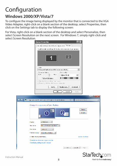
ConfigurationWindows 2000/XP/Vista/7To configure the image being displayed by the monitor that is connected to the VGA Video Adapter, right-click on a blank section of the desktop, select Properties, then click on the Settings tab to display the following screen:
For Vista, right-click on a blank section of the desktop and select Personalize, then select Screen Resolution on the next screen. For Windows 7, simply right-click and select Screen Resolution.

Instruction Manual9
Configure the secondary display by selecting it from the “Display” drop-down menu, then adjusting the desired settings:
Using the Second Display in Extended ModeIn Extended Mode, the monitor that is connected to the VGA Video Adapter creates an extension of the Windows Desktop displayed on the primary monitor. To set the display to function in this mode (once selected from the drop-down menu), check the box marked Extend my windows desktop onto this monitor, then arrange its position (virtually) with respect to the primary monitor by dragging the monitor icons (shown above as Primary/Secondary orientation) to reflect the physical orientation of the displays.
Using the Second Display in Clone Mode (default)In Clone Mode, the monitor that is connected to the VGA Video Adapter simply mirrors the image displayed on the primary monitor. To set the display to function in this mode (once selected from the drop-down menu), uncheck the box marked Extend my windows desktop onto this monitor (2000/XP) or change the “Multiple displays” setting (Vista/7).
Designating the Primary DisplayTo select which of the connected monitors will act as the primary display, select the monitor that will be used as the Primary Display from the Drop-down menu (referenced on page 4), and place a checkmark next to Use this device as the primary monitor. On some displays it is necessary to disable the main display (i.e. uncheck the box marked Extend my Windows display onto this monitor for the main display).
Following this change, the monitor connected to the VGA Video Adapter will remain set as the primary display even if the computer enters hibernate mode or operation is suspended or powered down. If the monitor is disconnected from the VGA Video Adapter, or the VGA Video Adapter is removed from the host computer, the original monitor will revert to being the primary display.
Alternate ConfigurationFollowing the software installation for the VGA Video Adapter, you may have noticed an icon in the taskbar as illustrated below. Clicking on this icon will open a menu that offers configuration of the display (connected to the VGA Video Adapter):
Here, you can set the secondary display to act as an extension of the primary desktop, or as a mirror image that duplicates the contents on the primary display.
Instruction Manual10
Similarly, the screen resolution, color quality, position of the screen and rotation of the screen can be adjusted from this menu.
To disable the secondary display, select Off.
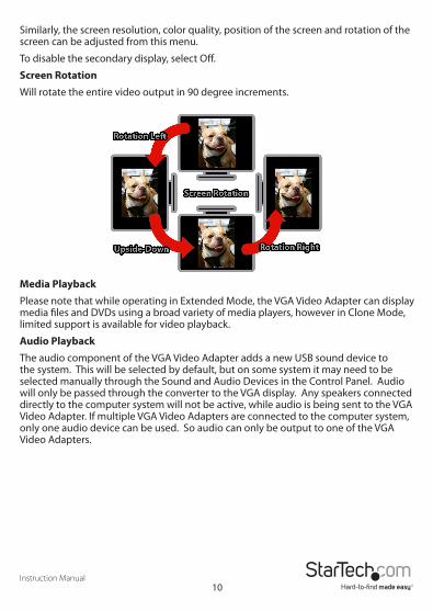
Screen RotationWill rotate the entire video output in 90 degree increments.
Media PlaybackPlease note that while operating in Extended Mode, the VGA Video Adapter can display media files and DVDs using a broad variety of media players, however in Clone Mode, limited support is available for video playback.
Audio PlaybackThe audio component of the VGA Video Adapter adds a new USB sound device to the system. This will be selected by default, but on some system it may need to be selected manually through the Sound and Audio Devices in the Control Panel. Audio will only be passed through the converter to the VGA display. Any speakers connected directly to the computer system will not be active, while audio is being sent to the VGA Video Adapter. If multiple VGA Video Adapters are connected to the computer system, only one audio device can be used. So audio can only be output to one of the VGA Video Adapters.

Instruction Manual11
Mac OS XTo configure the display settings and monitor positions, bring up the Displays Preferences from the System Preferences menu:
The Display settings for each display will appear on the individual monitors themselves. To configure them all from a single location, press the “Gather Windows” button and each screen’s Displays Preferences windows will appear on that display.
All supported video resolutions will appear in the list on the left side. To change the positioning of each display, click on the “Arrangement“ button (found only on the primary display) and you can then virtually reposition each display.
Using the Adapter in Extended or Mirror Mode
By default the USB Video Adapter will be setup as an extended display. To change the display as a mirrored/cloned display, check the “Mirror Display” box on the “Arrangement” page for that monitors Displays settings window. To return the monitor to an extended display, uncheck this option.

Instruction Manual12
To use both extended and mirrored displays simultaneously, turn off mirroring then in the “Arrangement” page press and hold the ‘cmd’ and ‘alt’ keys and drag and drop the display you wish to mirror over the primary display (shown with the white bar).
Repeat this with each display you wish to mirror, all others will act as an extended display.
Changing the Primary Display
You can change which display is the primary display by moving the Menu Bar between displays. Changing the primary display affects where new windows appear and the position of the Dock.
To move the Menu Bar, click the white menu bar and drag it to the display you wish to become the primary.
Configuring Displays from the Menu Bar
If you have checked the “Show displays in menu bar” in the Display Preferences window, then you can configure displays by clicking the display icon in the menu bar. This will show a menu similar to the following:
Media Playback
Please note that while operating in Extended Mode, the USB Display Adapter can display media files and DVDs using a broad variety of media players, however in Clone Mode, limited support is available for video playback.
Audio Playback
The audio component of the VGA Video Adapter adds a new USB sound device to the system. This will be selected by default, but on some system it may need to be selected manually through the Sound Preferences in System Preferences. Audio will only be passed through the converter to the VGA display. Any speakers connected directly to the computer system will not be active, while audio is being sent to the VGA Video Adapter. If multiple VGA Video Adapters are connected to the computer system, only one audio device can be used. So audio can only be output to one of the VGA Video Adapters.

Instruction Manual13
Specifications
Bus InterfaceUSB 2.0
TCP/IP
Video Signal VGA (RGBHV)
Connectors
1 x DE-15 VGA female
1 x USB mini-B female
2 x 3.5mm mini-jack female
1 x RJ45 female
2 x USB type A female
1 x DC Power
LEDs1 x Power
1 x RJ45 Link
1 x RJ45 Activity
Maximum Video Resolution 1920x1080
Audio Support Yes
Supported Number of Adapters (per system)
USB: 4 Ethernet: 1
Maximum Data Transfer RateUSB 2.0: 480Mbps
Ethernet: 1000Mbps
Power Adapter 5VDC, 2000mA
Operating Temperature 0°C ~ 40°C (32°C ~ 104°C)
Storage Temperature -20°C ~ 60°C (-4°C ~ 140°C)
Humidity 20 ~ 90% RH
Dimensions 133.0mm x 71.0mm x 27.0mm
Weight 142g
Compatible Operating Systems* Windows 2000/XP (32-bit), Vista/7 (32/64-bit), Mac OS 10.4.11/10.5/10.6
*only USB mode is supported in Mac OS

Instruction Manual14
Technical SupportStarTech.com’s lifetime technical support is an integral part of our commitment to provide industry-leading solutions. If you ever need help with your product, visit www.startech.com/support and access our comprehensive selection of online tools, documentation, and downloads.For the latest drivers/software, please visit www.startech.com/downloads
Warranty InformationThis product is backed by a two year warranty. In addition, StarTech.com warrants its products against defects in materials and workmanship for the periods noted, following the initial date of purchase. During this period, the products may be returned for repair, or replacement with equivalent products at our discretion. The warranty covers parts and labor costs only. StarTech.com does not warrant its products from defects or damages arising from misuse, abuse, alteration, or normal wear and tear.
Limitation of LiabilityIn no event shall the liability of StarTech.com Ltd. and StarTech.com USA LLP (or their officers, directors, employees or agents) for any damages (whether direct or indirect, special, punitive, incidental, consequential, or otherwise), loss of profits, loss of business, or any pecuniary loss, arising out of or related to the use of the product exceed the actual price paid for the product. Some states do not allow the exclusion or limitation of incidental or consequential damages. If such laws apply, the limitations or exclusions contained in this statement may not apply to you.

Hard-to-find made easy. At StarTech.com, that isn’t a slogan. It’s a promise.
StarTech.com is your one-stop source for every connectivity part you need. From the latest technology to legacy products — and all the parts that bridge the old and new — we can help you find the parts that connect your solutions.
We make it easy to locate the parts, and we quickly deliver them wherever they need to go. Just talk to one of our tech advisors or visit our website. You’ll be connected to the products you need in no time.
Visit www.startech.com for complete information on all StarTech.com products and to access exclusive resources and time-saving tools.
StarTech.com is an ISO 9001 Registered manufacturer of connectivity and technology parts. StarTech.com was founded in 1985 and has operations in the United States, Canada, the United Kingdom and Taiwan servicing a worldwide market.