ethernet surge protective device (spd) electrical design ... · presented by: mick maytum ict surge...
TRANSCRIPT
Presented by: Mick Maytum
ICT Surge Protection Expert ictsp-essays.info
Ethernet Surge Protective Device (SPD) Electrical Design Considerations
Contents
• Surge types Common-mode, Differential-mode unbalanced and balanced
• Ethernet system • Unexpected consequences
Surge generators, Protective functions • General
Port connections, Protective function • Surge tests
Common-mode, Differential-mode, Common-mode to differential-mode conversion, Durability, Cable screen terminal
• DC tests Insulation resistance, Voltage drop
• References
2/19/2017 Ethernet SPD Electrical Design
Considerations 2
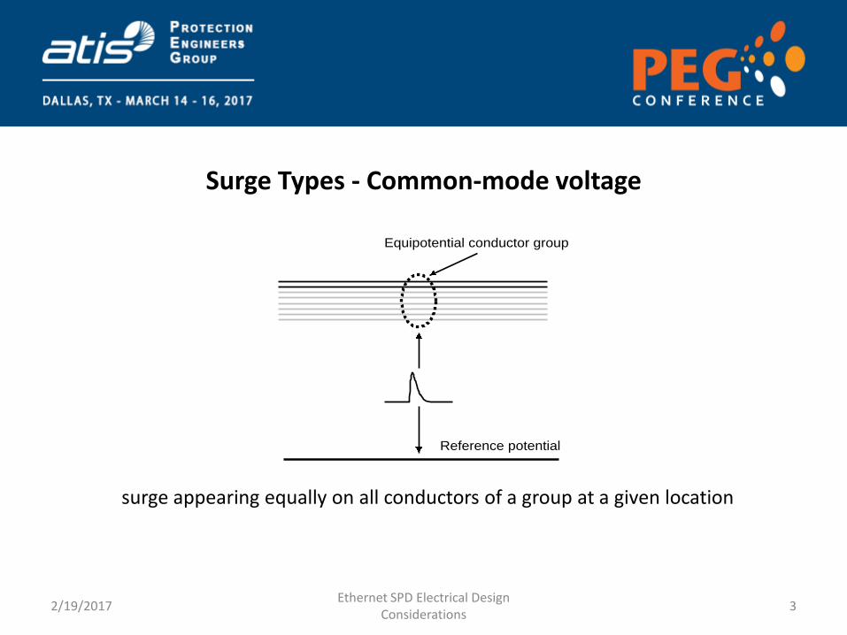
Surge Types - Common-mode voltage
2/19/2017 Ethernet SPD Electrical Design
Considerations 3
Equipotential conductor group
Reference potential
surge appearing equally on all conductors of a group at a given location
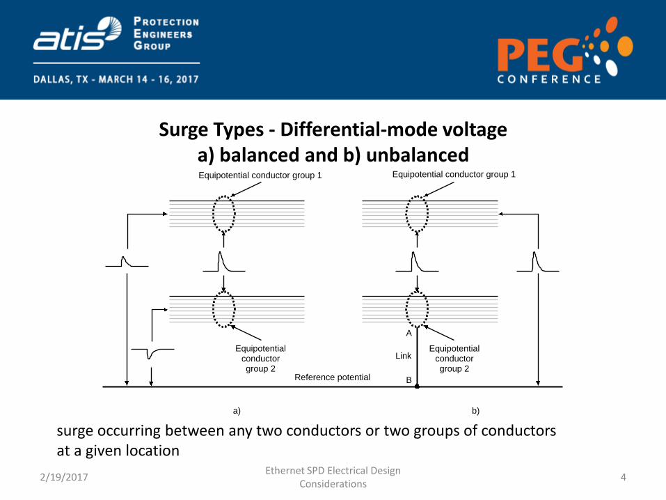
Surge Types - Differential-mode voltage a) balanced and b) unbalanced
2/19/2017 Ethernet SPD Electrical Design
Considerations 4
Reference potential
Equipotential conductor group 1
Equipotentialconductorgroup 2
Equipotential conductor group 1
Equipotentialconductorgroup 2
A
B
Link
a) b)
surge occurring between any two conductors or two groups of conductors at a given location
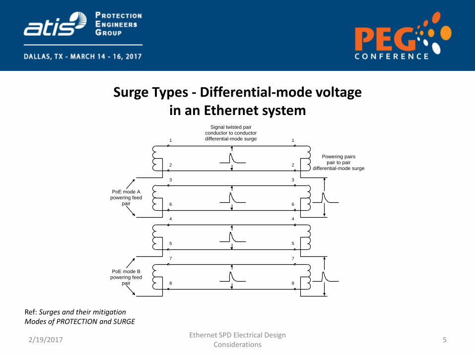
Surge Types - Differential-mode voltage in an Ethernet system
2/19/2017 Ethernet SPD Electrical Design
Considerations 5
Ref: Surges and their mitigation Modes of PROTECTION and SURGE
1
8
7
5
4
6
3
2
1
8
7
5
4
6
3
2
PoE mode Apowering feed
pair
PoE mode Bpowering feed
pair
Signal twisted pairconductor to conductordifferential-mode surge
Powering pairspair to pair
differential-mode surge
Ethernet system
• At surge frequencies the port loading is effectively resistive capacitive and non-linear.
• The port Ethernet transformer presents a d.c. load of about 1 W + 1 W
• The PoE PD circuits consists of a diode bridge, avalanche diode and capacitance.
• The PoE PSE circuits consists of a regulating IC, series pass element, some protection and capacitance.
• Most of the PoE PD and PSE ICs are rated about 100 V
2/19/2017 Ethernet SPD Electrical Design
Considerations 6
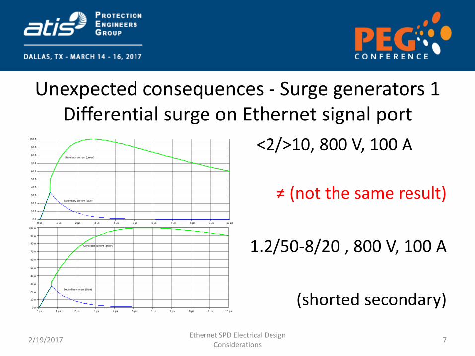
Unexpected consequences - Surge generators 1 Differential surge on Ethernet signal port
<2/>10, 800 V, 100 A
≠ (not the same result)
1.2/50-8/20 , 800 V, 100 A
(shorted secondary)
2/19/2017 Ethernet SPD Electrical Design
Considerations 7
0 µs 1 µs 2 µs 3 µs 4 µs 5 µs 6 µs 7 µs 8 µs 9 µs
0 A
10 A
20 A
30 A
40 A
50 A
60 A
70 A
80 A
90 A
100 A
10 µs
Secondary current (blue)
Generator current (green)
0 µs 1 µs 2 µs 3 µs 4 µs 5 µs 6 µs 7 µs 8 µs 9 µs
0 A
10 A
20 A
30 A
40 A
50 A
60 A
70 A
80 A
90 A
100 A
10 µs
Secondary current (blue)
Generator current (green)
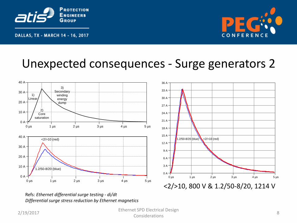
Unexpected consequences - Surge generators 2
2/19/2017 Ethernet SPD Electrical Design
Considerations 8
0 µs 1 µs 2 µs 3 µs 4 µs 5 µs
0 A
10 A
20 A
30 A
40 A
2)Core
saturation
1)Linear
3)Secondary
windingenergydump
0 µs 1 µs 2 µs 3 µs 4 µs 5 µs
0 A
10 A
20 A
30 A
40 A
1.2/50-8/20 (blue)
<2/>10 (red)
0 µs 1 µs 2 µs 3 µs 4 µs 5 µs
0 A
3 A
6 A
9 A
12 A
15 A
18 A
21 A
24 A
27 A
30 A
33 A
36 A
<2/>10 (red)1.2/50-8/20 (blue)
<2/>10, 800 V & 1.2/50-8/20, 1214 V Refs: Ethernet differential surge testing - di/dt Differential surge stress reduction by Ethernet magnetics
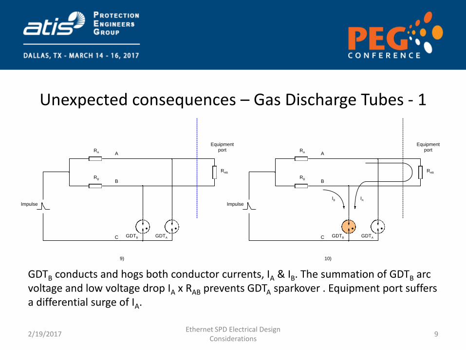
Unexpected consequences – Gas Discharge Tubes - 1
GDTB conducts and hogs both conductor currents, IA & IB. The summation of GDTB arc voltage and low voltage drop IA x RAB prevents GDTA sparkover . Equipment port suffers a differential surge of IA.
2/19/2017 Ethernet SPD Electrical Design
Considerations 9
9)
C
ARA
GDTB GDTA
Equipmentport
Impulse
BRB
RAB
10)
C
ARA
GDTB GDTA
Equipmentport
Impulse
BRB
RAB
IB IA
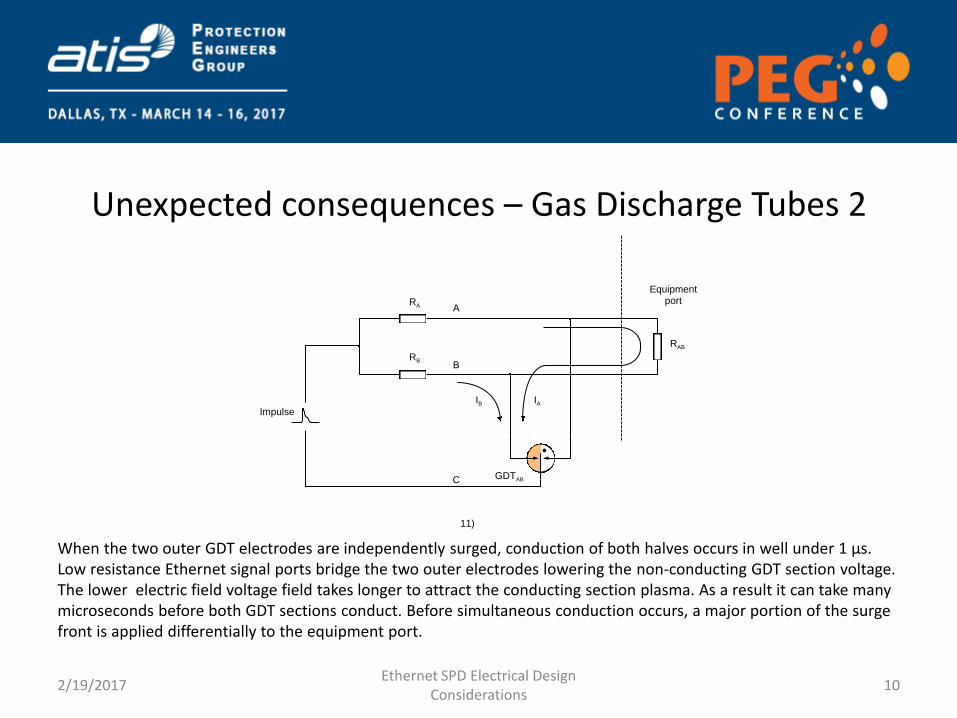
Unexpected consequences – Gas Discharge Tubes 2
When the two outer GDT electrodes are independently surged, conduction of both halves occurs in well under 1 µs. Low resistance Ethernet signal ports bridge the two outer electrodes lowering the non-conducting GDT section voltage. The lower electric field voltage field takes longer to attract the conducting section plasma. As a result it can take many microseconds before both GDT sections conduct. Before simultaneous conduction occurs, a major portion of the surge front is applied differentially to the equipment port.
2/19/2017 Ethernet SPD Electrical Design
Considerations 10
11)
C
ARA
GDTAB
Equipmentport
Impulse
BRB
RAB
IB IA
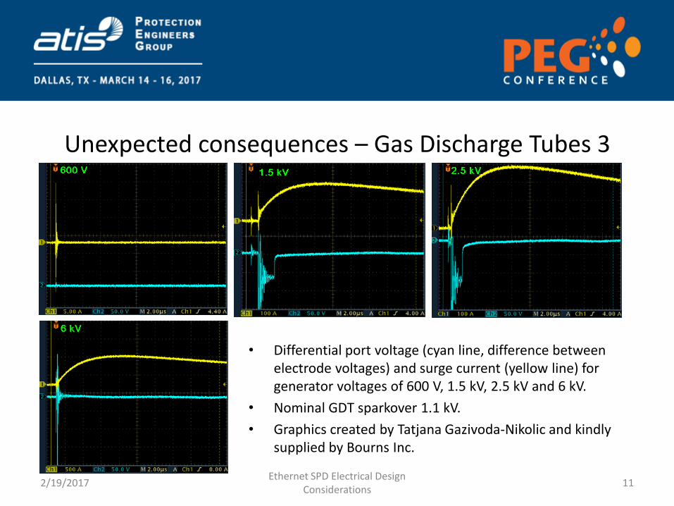
Unexpected consequences – Gas Discharge Tubes 3
• Differential port voltage (cyan line, difference between electrode voltages) and surge current (yellow line) for generator voltages of 600 V, 1.5 kV, 2.5 kV and 6 kV.
• Nominal GDT sparkover 1.1 kV.
• Graphics created by Tatjana Gazivoda-Nikolic and kindly supplied by Bourns Inc.
2/19/2017 Ethernet SPD Electrical Design
Considerations 11
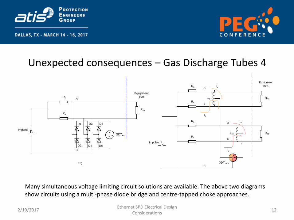
Unexpected consequences – Gas Discharge Tubes 4
Many simultaneous voltage limiting circuit solutions are available. The above two diagrams show circuits using a multi-phase diode bridge and centre-tapped choke approaches.
2/19/2017 Ethernet SPD Electrical Design
Considerations 12
12)
C
ARA
GDTAB
Equipmentport
Impulse
D1
RB
RAB
D2
D3
D4
D5
D6
ARA
C
Equipmentport
Impulse
BRB
RAB
IB
IA
LAB
GDTABDE
DRD
ERE
RDE
IE
ID
LDE
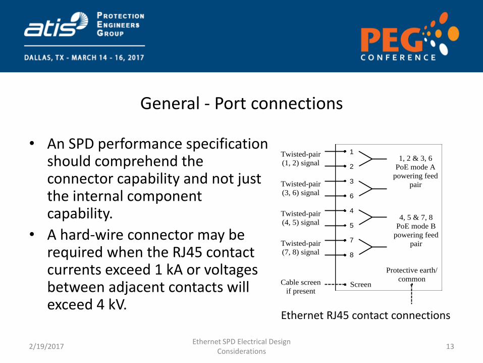
General - Port connections
• An SPD performance specification should comprehend the connector capability and not just the internal component capability.
• A hard-wire connector may be required when the RJ45 contact currents exceed 1 kA or voltages between adjacent contacts will exceed 4 kV.
2/19/2017 Ethernet SPD Electrical Design
Considerations 13
Screen
1, 2 & 3, 6
PoE mode A
powering feed
pair
1
8
7
5
4
6
3
2
Twisted-pair
(1, 2) signal
Twisted-pair
(7, 8) signal
Twisted-pair
(4, 5) signal
Twisted-pair
(3, 6) signal
4, 5 & 7, 8
PoE mode B
powering feed
pair
Cable screen
if present
Protective earth/
common
Ethernet RJ45 contact connections
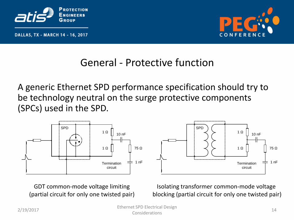
General - Protective function
A generic Ethernet SPD performance specification should try to be technology neutral on the surge protective components (SPCs) used in the SPD.
2/19/2017 Ethernet SPD Electrical Design
Considerations 14
Terminationcircuit
10 nF1 W
1 W 75 W
1 nF
SPD
Terminationcircuit
10 nF1 W
1 W 75 W
1 nF
SPD
GDT common-mode voltage limiting (partial circuit for only one twisted pair)
Isolating transformer common-mode voltage blocking (partial circuit for only one twisted pair)
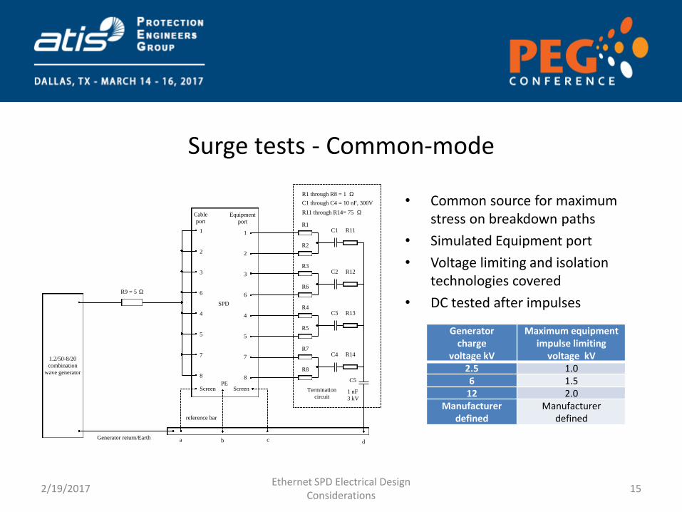
Surge tests - Common-mode
• Common source for maximum stress on breakdown paths
• Simulated Equipment port
• Voltage limiting and isolation technologies covered
• DC tested after impulses
2/19/2017 Ethernet SPD Electrical Design
Considerations 15
1.2/50-8/20
combination
wave generator
SPD
Generator return/Earth
ScreenPE
ba
reference bar
7
4
6
5
3
2
8
1
R9 = 5 W
Cable
portEquipment
port
R1 through R8 = 1 W
R1
R2
R3
R6
R4
R5
R7
R8
7
4
6
5
3
2
8
1
C1 through C4 = 10 nF, 300V
C1
C2
C3
C4
R11
R12
R13
R14
R11 through R14= 75 W
C5
1 nF
3 kV
Termination
circuit
d
Screen
c
Generator charge
voltage kV
Maximum equipment impulse limiting
voltage kV
2.5 1.0
6 1.5
12 2.0
Manufacturer defined
Manufacturer defined
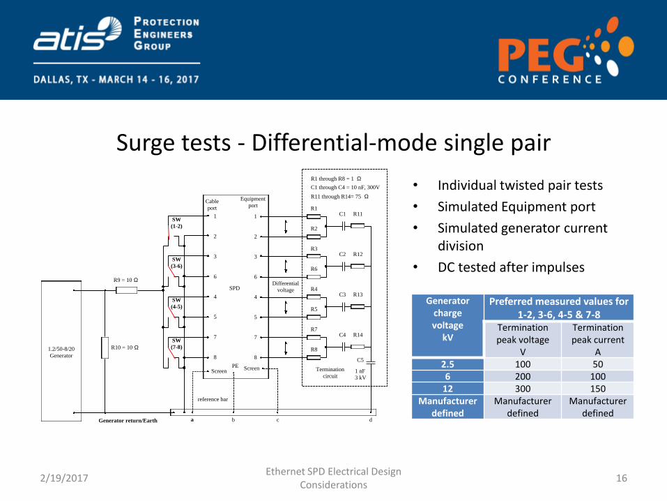
Surge tests - Differential-mode single pair
• Individual twisted pair tests
• Simulated Equipment port
• Simulated generator current division
• DC tested after impulses
2/19/2017 Ethernet SPD Electrical Design
Considerations 16
SPD
ScreenPE
b
reference bar
Cable
port
Equipment
port
R1 through R8 = 1 W
R1
R2
R3
R6
R4
R5
R7
R8
7
4
6
5
3
2
8
1
C1 through C4 = 10 nF, 300V
C1
C2
C3
C4
R11
R12
R13
R14
R11 through R14= 75 W
C5
1 nF
3 kV
Termination
circuit
d
Screen
Generator return/Earth a
SW
(1-2)
SW
(3-6)
SW
(4-5)
SW
(7-8)1.2/50-8/20
Generator
R9 = 10 W
R10 = 10 W
7
4
6
5
3
2
8
1
c
Differential
voltage
Generator charge voltage
kV
Preferred measured values for 1-2, 3-6, 4-5 & 7-8
Termination peak voltage
V
Termination peak current
A
2.5 100 50
6 200 100
12 300 150
Manufacturer defined
Manufacturer defined
Manufacturer defined
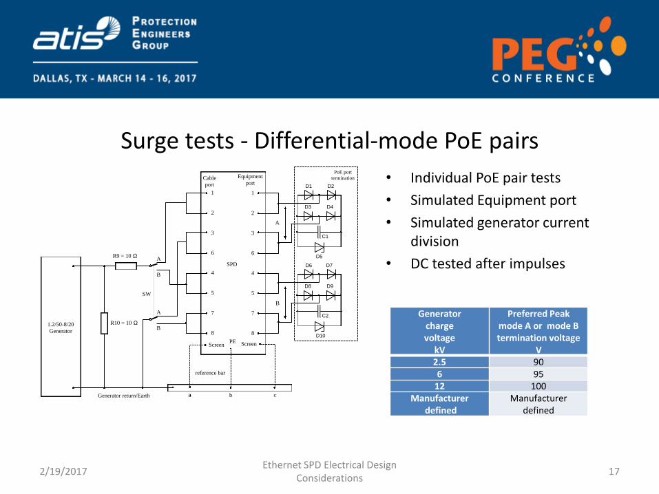
Surge tests - Differential-mode PoE pairs
• Individual PoE pair tests
• Simulated Equipment port
• Simulated generator current division
• DC tested after impulses
2/19/2017 Ethernet SPD Electrical Design
Considerations 17
SPD
ScreenPE
b
reference bar
Cable
port
Equipment
port
7
4
6
5
3
2
8
1
Screen
a
7
4
6
5
3
2
8
1
c
A
B
A
B
SW
Generator return/Earth
1.2/50-8/20
Generator
R9 = 10 W
R10 = 10 W
PoE port
termination
D1 D2
D3 D4
D5
C1
D6 D7
D8 D9
D10
C2
B
A
Generator charge voltage
kV
Preferred Peak mode A or mode B termination voltage
V
2.5 90
6 95
12 100
Manufacturer defined
Manufacturer defined
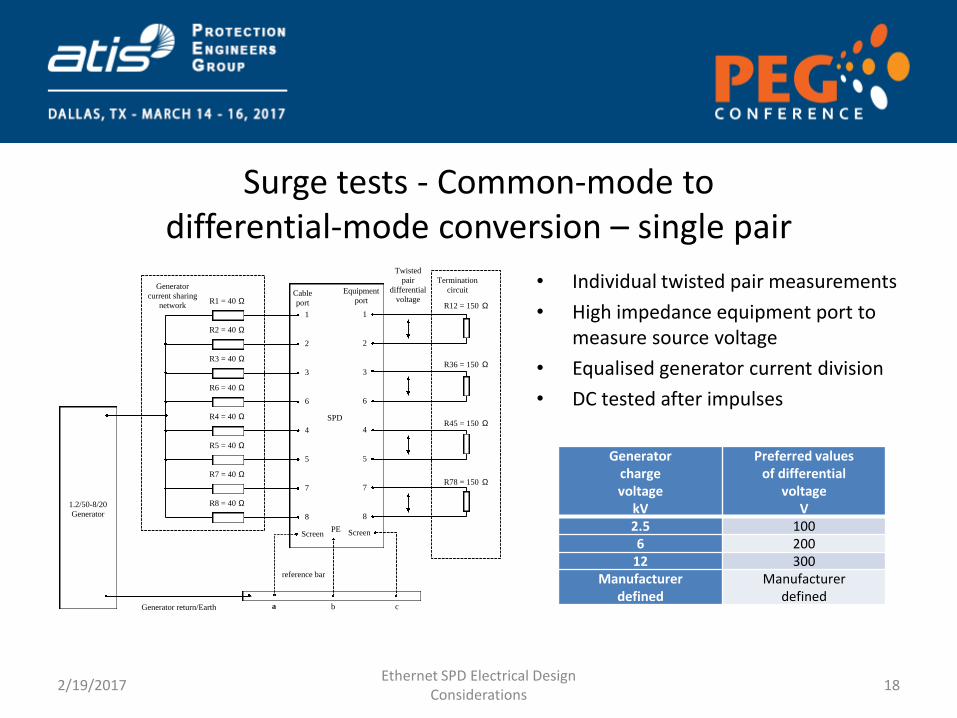
Surge tests - Common-mode to differential-mode conversion – single pair
• Individual twisted pair measurements
• High impedance equipment port to measure source voltage
• Equalised generator current division
• DC tested after impulses
2/19/2017 Ethernet SPD Electrical Design
Considerations 18
SPD
ScreenPE
b
reference bar
Equipment
port
Screen
a c
Cable
port
7
4
6
5
3
2
8
1
Generator return/Earth
1.2/50-8/20
Generator
R2 = 40 W
R3 = 40 W
R6 = 40 W
R4 = 40 W
R5 = 40 W
R7 = 40 W
R8 = 40 W
R1 = 40 WR12 = 150 W
7
4
6
5
3
2
8
1
Termination
circuit
Twisted
pair
differential
voltage
Generator
current sharing
network
R36 = 150 W
R45 = 150 W
R78 = 150 W
Generator charge voltage
kV
Preferred values of differential
voltage V
2.5 100
6 200
12 300
Manufacturer defined
Manufacturer defined
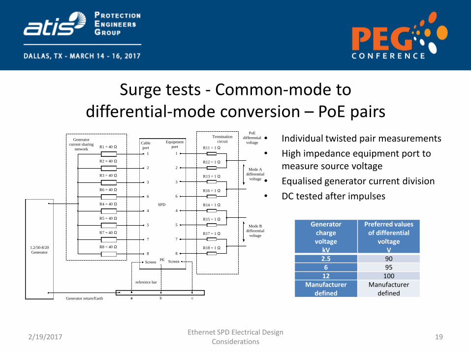
Surge tests - Common-mode to differential-mode conversion – PoE pairs
• Individual twisted pair measurements
• High impedance equipment port to measure source voltage
• Equalised generator current division
• DC tested after impulses
2/19/2017 Ethernet SPD Electrical Design
Considerations 19
Generator charge voltage
kV
Preferred values of differential
voltage V
2.5 90
6 95
12 100
Manufacturer defined
Manufacturer defined
SPD
ScreenPE
b
reference bar
Equipment
port
Screen
a c
Cable
port
7
4
6
5
3
2
8
1
Generator return/Earth
1.2/50-8/20
Generator
R2 = 40 W
R3 = 40 W
R6 = 40 W
R4 = 40 W
R5 = 40 W
R7 = 40 W
R8 = 40 W
R1 = 40 W
7
4
6
5
3
2
8
1
Termination
circuit
PoE
differential
voltageGenerator
current sharing
network
Mode B
differential
voltage
Mode A
differential
voltage
R12 = 1 W
R13 = 1 W
R16 = 1 W
R14 = 1 W
R15 = 1 W
R17 = 1 W
R18 = 1 W
R11 = 1 W

Surge tests - Durability
• Little attention is given to impulse durability rather than big number single impulse ratings
• Over life SPDs may experience many thousands of surges not just one big one
• Further depending on the technology the single and multi-impulse ratings maybe the same (silicon junction) or require major rating reduction due to wear-out (MOVs)
• It makes sense to know what the SPD 100 impulse or more impulse rating is
2/19/2017 Ethernet SPD Electrical Design
Considerations 20

Surge tests - Cable screen terminal
Generator charge voltage
kV
Maximum screen to PE voltage,
SW positions 1 & 2 V
Maximum screen to screen voltage,
SW position 3 V
2.5 40 80
6 90 180
12 180 360
Manufacturer defined
Manufacturer defined
Manufacturer defined
2/19/2017 Ethernet SPD Electrical Design
Considerations 21
SPD
ScreenPE
b
reference bar
Cable
port
Equipment
port
7
4
6
5
3
2
8
1
Screen
7
4
6
5
3
2
8
1
1
2
SW
Generator return/Earth
1.2/50-8/20
Generator
R9 = 5 W
3
1
2
3
• Values based on IEC 60603-7-7 • SW position 1 checks cable port screen terminal to
protective earth (PE) terminal bonding • SW position 2 checks equipment port screen
terminal to protective earth (PE) terminal bonding • SW position 3 checks cable port screen terminal to
the equipment port screen terminal.
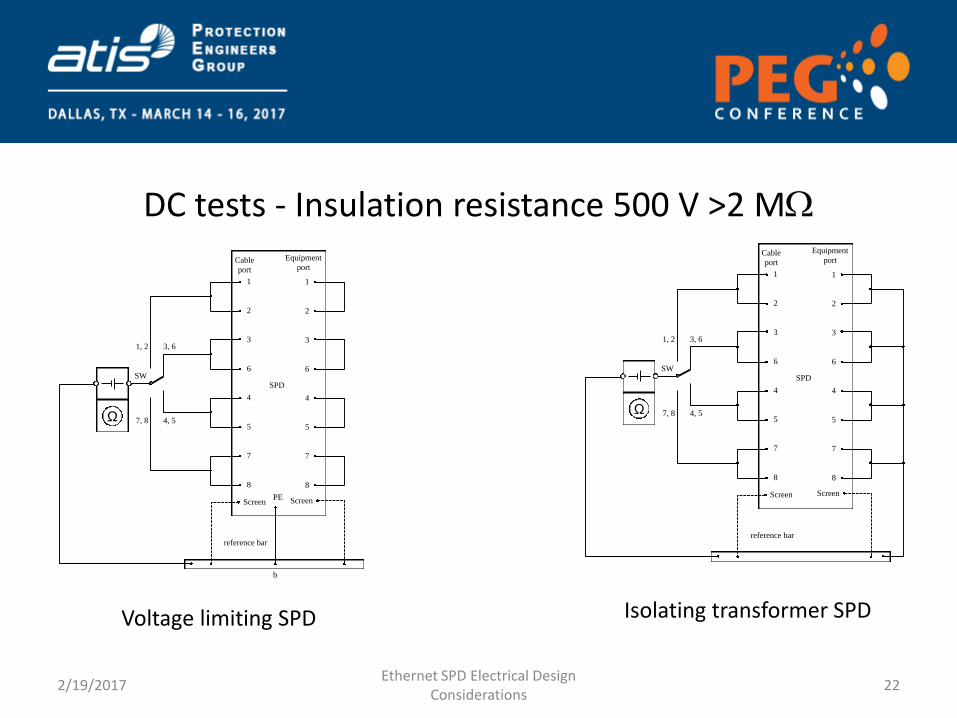
DC tests - Insulation resistance 500 V >2 MW
Voltage limiting SPD
2/19/2017 Ethernet SPD Electrical Design
Considerations 22
SPD
ScreenPE
b
reference bar
Cable
port
Equipment
port
7
4
6
5
3
2
8
1
Screen
7
4
6
5
3
2
8
1
W
SW
7, 8
1, 2 3, 6
4, 5
SPD
Screen
reference bar
Cable
port
Equipment
port
7
4
6
5
3
2
8
1
Screen
7
4
6
5
3
2
8
1
W
SW
7, 8
1, 2 3, 6
4, 5
Isolating transformer SPD
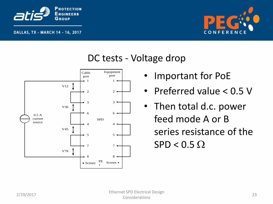
DC tests - Voltage drop
• Important for PoE
• Preferred value < 0.5 V
• Then total d.c. power feed mode A or B series resistance of the SPD < 0.5 W
2/19/2017 Ethernet SPD Electrical Design
Considerations 23
SPD
ScreenPE
Equipment
port
Screen
Cable
port
7
4
6
5
3
2
8
1
7
4
6
5
3
2
8
1
V12
V36
V45
V78
0.5 A
current
source
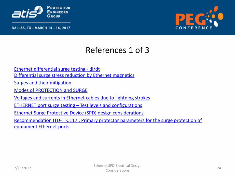
References 1 of 3
Ethernet differential surge testing - di/dt Differential surge stress reduction by Ethernet magnetics
Surges and their mitigation
Modes of PROTECTION and SURGE
Voltages and currents in Ethernet cables due to lightning strokes
ETHERNET port surge testing – Test levels and configurations
Ethernet Surge Protective Device (SPD) design considerations
Recommendation ITU-T K.117 : Primary protector parameters for the surge protection of equipment Ethernet ports
2/19/2017 Ethernet SPD Electrical Design
Considerations 24
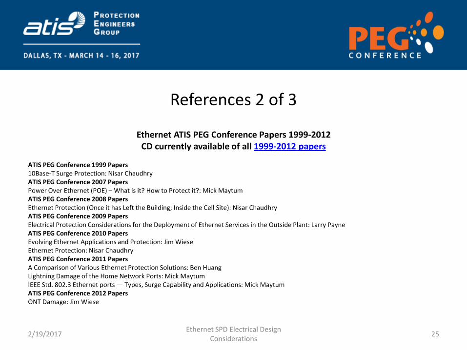
References 2 of 3
Ethernet ATIS PEG Conference Papers 1999-2012 CD currently available of all 1999-2012 papers
ATIS PEG Conference 1999 Papers 10Base-T Surge Protection: Nisar Chaudhry ATIS PEG Conference 2007 Papers Power Over Ethernet (POE) – What is it? How to Protect it?: Mick Maytum ATIS PEG Conference 2008 Papers Ethernet Protection (Once it has Left the Building; Inside the Cell Site): Nisar Chaudhry ATIS PEG Conference 2009 Papers Electrical Protection Considerations for the Deployment of Ethernet Services in the Outside Plant: Larry Payne ATIS PEG Conference 2010 Papers Evolving Ethernet Applications and Protection: Jim Wiese Ethernet Protection: Nisar Chaudhry ATIS PEG Conference 2011 Papers A Comparison of Various Ethernet Protection Solutions: Ben Huang Lightning Damage of the Home Network Ports: Mick Maytum IEEE Std. 802.3 Ethernet ports — Types, Surge Capability and Applications: Mick Maytum ATIS PEG Conference 2012 Papers ONT Damage: Jim Wiese
2/19/2017 Ethernet SPD Electrical Design
Considerations 25
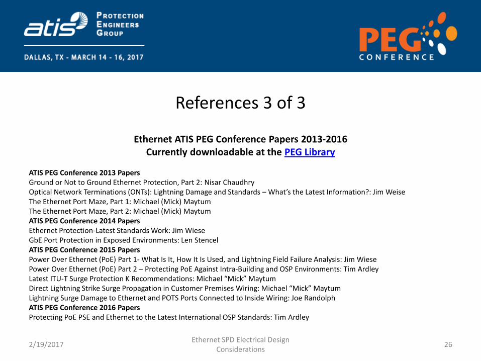
References 3 of 3
Ethernet ATIS PEG Conference Papers 2013-2016 Currently downloadable at the PEG Library
ATIS PEG Conference 2013 Papers Ground or Not to Ground Ethernet Protection, Part 2: Nisar Chaudhry Optical Network Terminations (ONTs): Lightning Damage and Standards – What’s the Latest Information?: Jim Weise The Ethernet Port Maze, Part 1: Michael (Mick) Maytum The Ethernet Port Maze, Part 2: Michael (Mick) Maytum ATIS PEG Conference 2014 Papers Ethernet Protection-Latest Standards Work: Jim Wiese GbE Port Protection in Exposed Environments: Len Stencel ATIS PEG Conference 2015 Papers Power Over Ethernet (PoE) Part 1- What Is It, How It Is Used, and Lightning Field Failure Analysis: Jim Wiese Power Over Ethernet (PoE) Part 2 – Protecting PoE Against Intra-Building and OSP Environments: Tim Ardley Latest ITU-T Surge Protection K Recommendations: Michael “Mick” Maytum Direct Lightning Strike Surge Propagation in Customer Premises Wiring: Michael “Mick” Maytum Lightning Surge Damage to Ethernet and POTS Ports Connected to Inside Wiring: Joe Randolph ATIS PEG Conference 2016 Papers Protecting PoE PSE and Ethernet to the Latest International OSP Standards: Tim Ardley
2/19/2017 Ethernet SPD Electrical Design
Considerations 26