ether io24 tcp - elexol.com · ether io24 tcp datasheet 1 ether io24 tcp the ether io24 tcp...
TRANSCRIPT
1 ETHER IO24 TCP DATASHEET
ETHER IO24 TCP
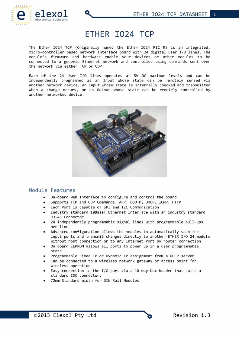
The Ether IO24 TCP (Originally named the Ether IO24 PIC R) is an integrated, micro‐controller based network interface board with 24 digital user I/O lines. The module’s firmware and hardware enable your devices or other modules to be connected to a generic Ethernet network and controlled using commands sent over the network via either TCP or UDP. Each of the 24 User I/O lines operates at 5V DC maximum levels and can be independently programmed as an Input whose state can be remotely sensed via another network device, an Input whose state is internally checked and transmitted when a change occurs, or an Output whose state can be remotely controlled by another networked device.
Module Features
• On‐board Web Interface to configure and control the board • Supports TCP and UDP Commands, ARP, BOOTP, DHCP, ICMP, HTTP • Each Port is capable of SPI and I2C Communication • Industry standard 10BaseT Ethernet Interface with an industry standard
RJ‐45 Connector • 24 independently programmable signal lines with programmable pull‐ups
per line • Advanced configuration allows the modules to automatically scan the
input ports and transmit changes directly to another ETHER I/O 24 module without host connection or to any Internet Port by router connection
• On board EEPROM allows all ports to power up in a user programmable state
• Programmable Fixed IP or Dynamic IP assignment from a DHCP server • Can be connected to a wireless network gateway or access point for
wireless operation • Easy connection to the I/O port via a 10‐way box header that suits a
standard IDC connector. • 72mm Standard width for DIN Rail Modules
©2013 Elexol Pty Ltd Revision 1.3
2 ETHER IO24 TCP DATASHEET
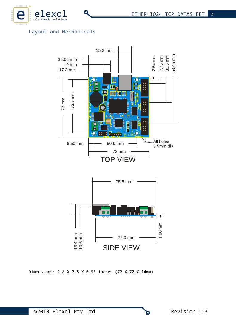
Layout and Mechanicals
TOP VIEW
50.9 mm6.50 mm
72 mm
72 m
m
63.5
mm
2.64
mm
7.75
mm
30.6
mm
53.4
5 m
m
All holes3.5mm dia
9 mm17.3 mm
20M
00
35.68 mm
15.3 mm
SIDE VIEW
1.60
mm
75.5 mm
72.0 mm
10.6
mm
13.4
mm
Dimensions: 2.8 X 2.8 X 0.55 inches (72 X 72 X 14mm)
©2013 Elexol Pty Ltd Revision 1.3
©2013 Elexol Pty Ltd Revision 1.3
3 ETHER IO24 TCP DATASHEET
Pinouts and Board Connections
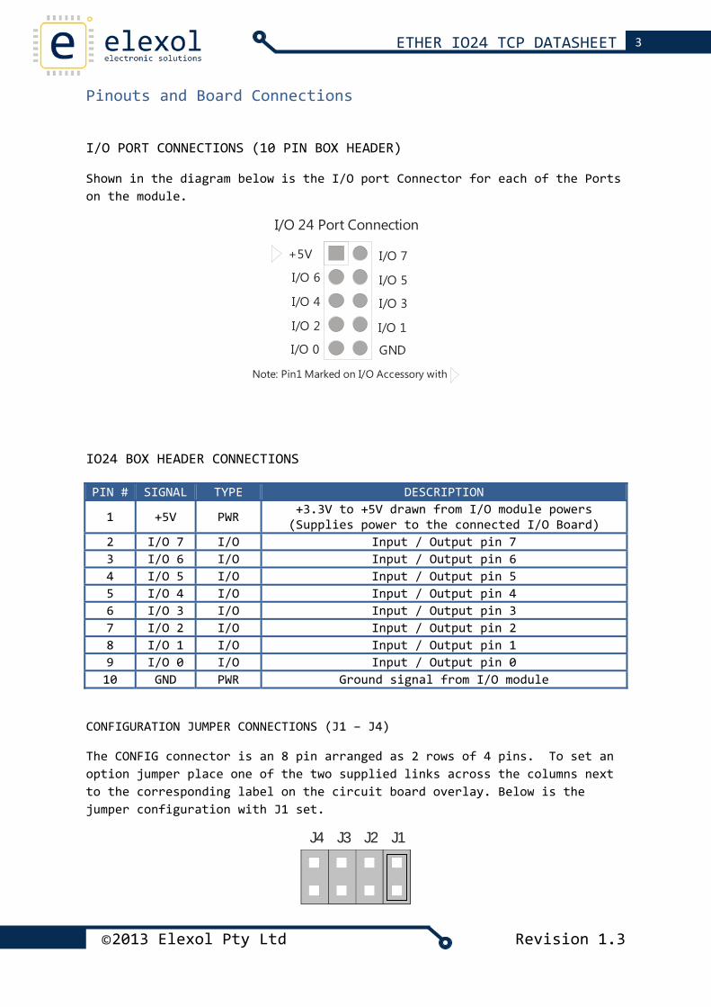
I/O PORT CONNECTIONS (10 PIN BOX HEADER)
Shown in the diagram below is the I/O port Connector for each of the Ports on the module.
Note: Pin1 Marked on I/O Accessory with
+5V I/O 7
I/O 5
I/O 3
I/O 1
I/O 6
I/O 4
I/O 2
I/O 0 GND
I/O 24 Port Connection
IO24 BOX HEADER CONNECTIONS PIN # SIGNAL TYPE DESCRIPTION
1 +5V PWR +3.3V to +5V drawn from I/O module powers (Supplies power to the connected I/O Board)
2 I/O 7 I/O Input / Output pin 7 3 I/O 6 I/O Input / Output pin 6 4 I/O 5 I/O Input / Output pin 5 5 I/O 4 I/O Input / Output pin 4 6 I/O 3 I/O Input / Output pin 3 7 I/O 2 I/O Input / Output pin 2 8 I/O 1 I/O Input / Output pin 1 9 I/O 0 I/O Input / Output pin 0 10 GND PWR Ground signal from I/O module
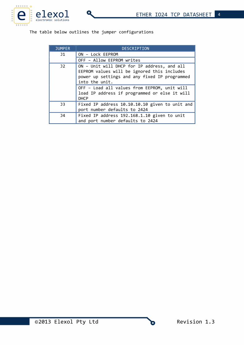
CONFIGURATION JUMPER CONNECTIONS (J1 – J4)
The CONFIG connector is an 8 pin arranged as 2 rows of 4 pins. To set an option jumper place one of the two supplied links across the columns next to the corresponding label on the circuit board overlay. Below is the jumper configuration with J1 set.
J4 J3 J1J2
4 ETHER IO24 TCP DATASHEET
The table below outlines the jumper configurations
JUMPER DESCRIPTION J1 ON – Lock EEPROM
OFF – Allow EEPROM writes J2 ON – Unit will DHCP for IP address, and all
EEPROM values will be ignored this includes power up settings and any fixed IP programmed into the unit. OFF – Load all values from EEPROM, unit will load IP address if programmed or else it will DHCP
J3 Fixed IP address 10.10.10.10 given to unit and port number defaults to 2424
J4 Fixed IP address 192.168.1.10 given to unit and port number defaults to 2424
©2013 Elexol Pty Ltd Revision 1.3
5 ETHER IO24 TCP DATASHEET
POWER CONNECTORS
The Module has a 2.1mm DC jack that is configured as Positive Centre pin with ground sleeve. The DC Jack is mounted overhanging the board’s edge in order that the module can be mounted with the network connector and power connector protruding through a case. There is an additional screw terminal connection that allows for the 5v supply from the onboard regulator to be used to power user circuits and sensors. The maximum current that user circuits may draw from the on board regulator is 500mA; if this current is exceeded then the operation of the board may be adversely affected.
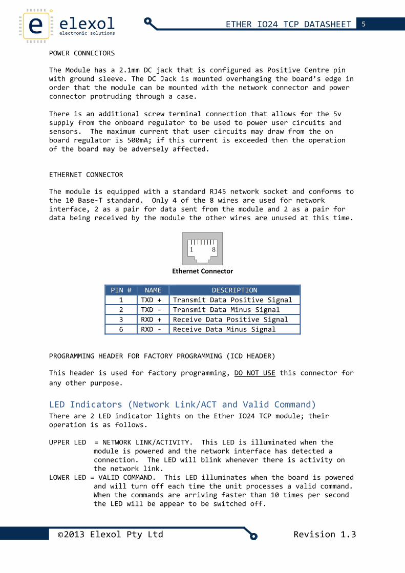
ETHERNET CONNECTOR
The module is equipped with a standard RJ45 network socket and conforms to the 10 Base‐T standard. Only 4 of the 8 wires are used for network interface, 2 as a pair for data sent from the module and 2 as a pair for data being received by the module the other wires are unused at this time.
1 8
Ethernet Connector
PIN # NAME DESCRIPTION
1 TXD + Transmit Data Positive Signal 2 TXD ‐ Transmit Data Minus Signal 3 RXD + Receive Data Positive Signal 6 RXD ‐ Receive Data Minus Signal
PROGRAMMING HEADER FOR FACTORY PROGRAMMING (ICD HEADER)
This header is used for factory programming, DO NOT USE this connector for any other purpose.
LED Indicators (Network Link/ACT and Valid Command) There are 2 LED indicator lights on the Ether IO24 TCP module; their operation is as follows.
UPPER LED = NETWORK LINK/ACTIVITY. This LED is illuminated when the
module is powered and the network interface has detected a connection. The LED will blink whenever there is activity on the network link.
LOWER LED = VALID COMMAND. This LED illuminates when the board is powered and will turn off each time the unit processes a valid command. When the commands are arriving faster than 10 times per second the LED will be appear to be switched off.
©2013 Elexol Pty Ltd Revision 1.3
6 ETHER IO24 TCP DATASHEET
Java Programming Interface The Ether IO24 TCP has an on board web interface that is used to configure all options for the module. This interface can be accessed via any java enabled web browser. The following section describes all features incorporated in the interface.
MODULE CONFIGURATION AND POWER UP SETTINGS USING THE WEB INTERFACE
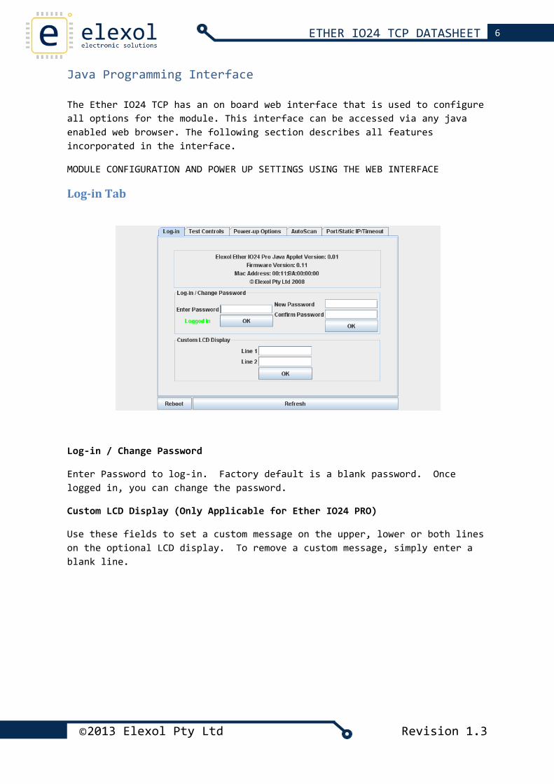
Log‐in Tab
Log‐in / Change Password
Enter Password to log‐in. Factory default is a blank password. Once logged in, you can change the password.
Custom LCD Display (Only Applicable for Ether IO24 PRO)
Use these fields to set a custom message on the upper, lower or both lines on the optional LCD display. To remove a custom message, simply enter a blank line.
©2013 Elexol Pty Ltd Revision 1.3
7 ETHER IO24 TCP DATASHEET
Test Controls
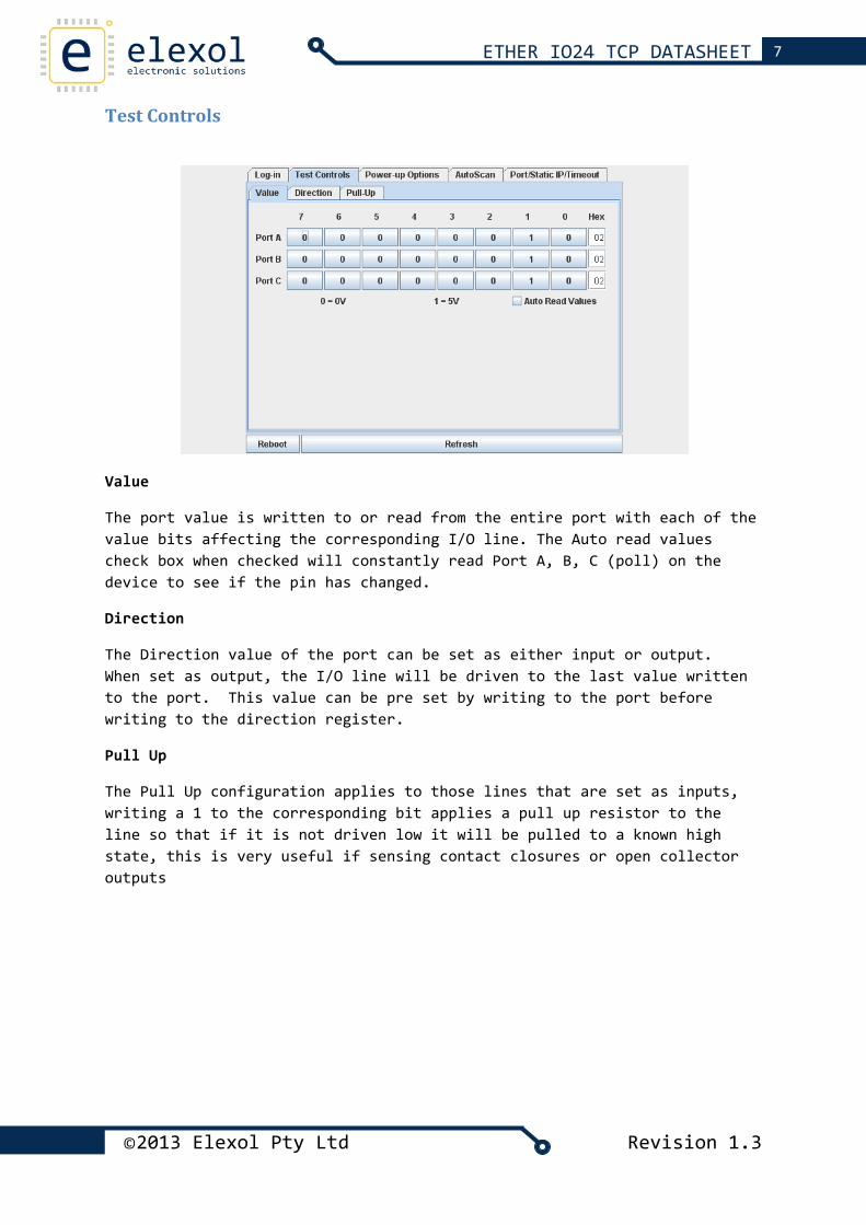
Value
The port value is written to or read from the entire port with each of the value bits affecting the corresponding I/O line. The Auto read values check box when checked will constantly read Port A, B, C (poll) on the device to see if the pin has changed.
Direction
The Direction value of the port can be set as either input or output. When set as output, the I/O line will be driven to the last value written to the port. This value can be pre set by writing to the port before writing to the direction register.
Pull Up
The Pull Up configuration applies to those lines that are set as inputs, writing a 1 to the corresponding bit applies a pull up resistor to the line so that if it is not driven low it will be pulled to a known high state, this is very useful if sensing contact closures or open collector outputs
©2013 Elexol Pty Ltd Revision 1.3
8 ETHER IO24 TCP DATASHEET
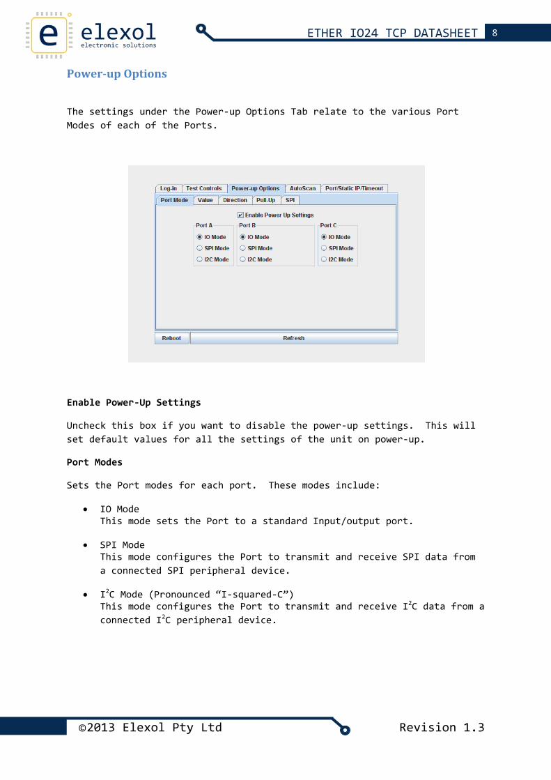
Power‐up Options
The settings under the Power‐up Options Tab relate to the various Port Modes of each of the Ports.
Enable Power‐Up Settings
Uncheck this box if you want to disable the power‐up settings. This will set default values for all the settings of the unit on power‐up.
Port Modes
Sets the Port modes for each port. These modes include:
• IO Mode This mode sets the Port to a standard Input/output port.
• SPI Mode This mode configures the Port to transmit and receive SPI data from a connected SPI peripheral device.
• I2C Mode (Pronounced “I‐squared‐C”) This mode configures the Port to transmit and receive I2C data from a connected I2C peripheral device.
©2013 Elexol Pty Ltd Revision 1.3
9 ETHER IO24 TCP DATASHEET
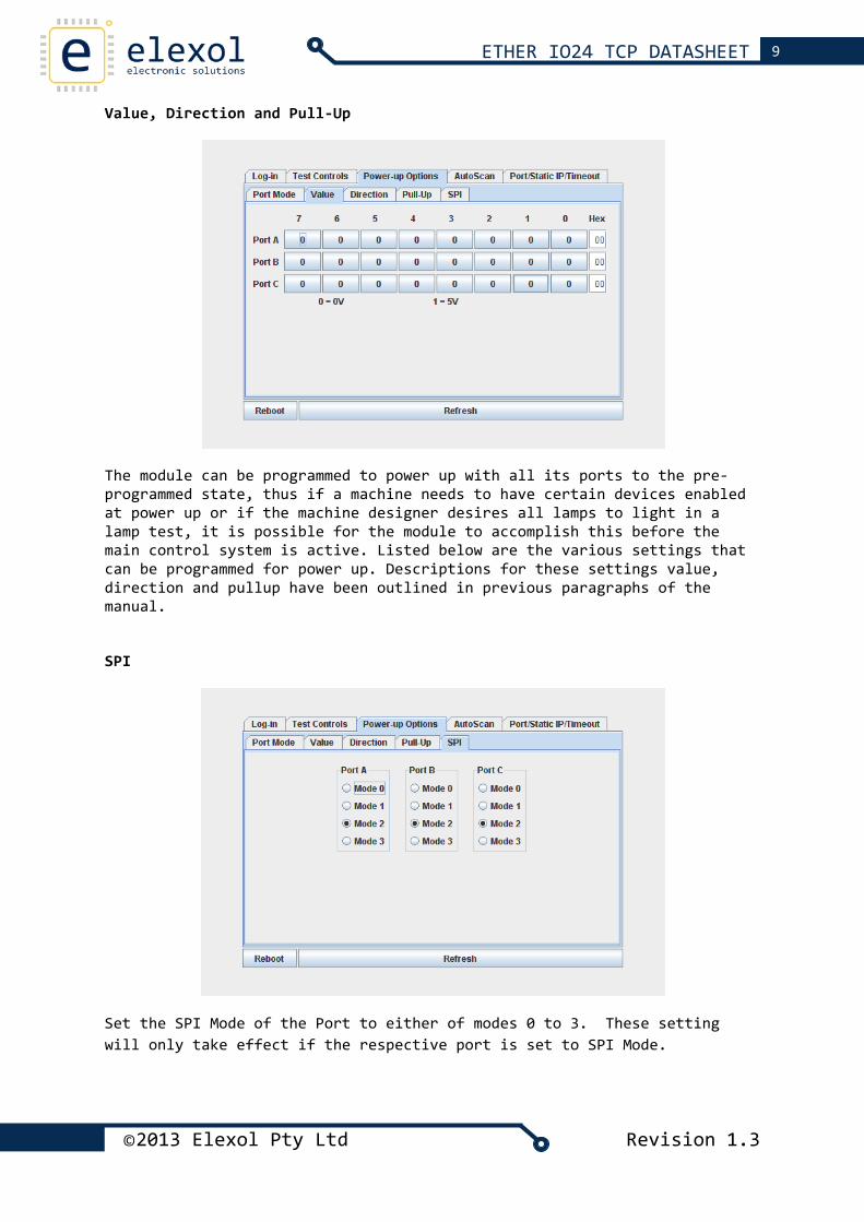
Value, Direction and Pull‐Up
The module can be programmed to power up with all its ports to the pre‐programmed state, thus if a machine needs to have certain devices enabled at power up or if the machine designer desires all lamps to light in a lamp test, it is possible for the module to accomplish this before the main control system is active. Listed below are the various settings that can be programmed for power up. Descriptions for these settings value, direction and pullup have been outlined in previous paragraphs of the manual.
SPI
Set the SPI Mode of the Port to either of modes 0 to 3. These setting will only take effect if the respective port is set to SPI Mode.
©2013 Elexol Pty Ltd Revision 1.3
10 ETHER IO24 TCP DATASHEET
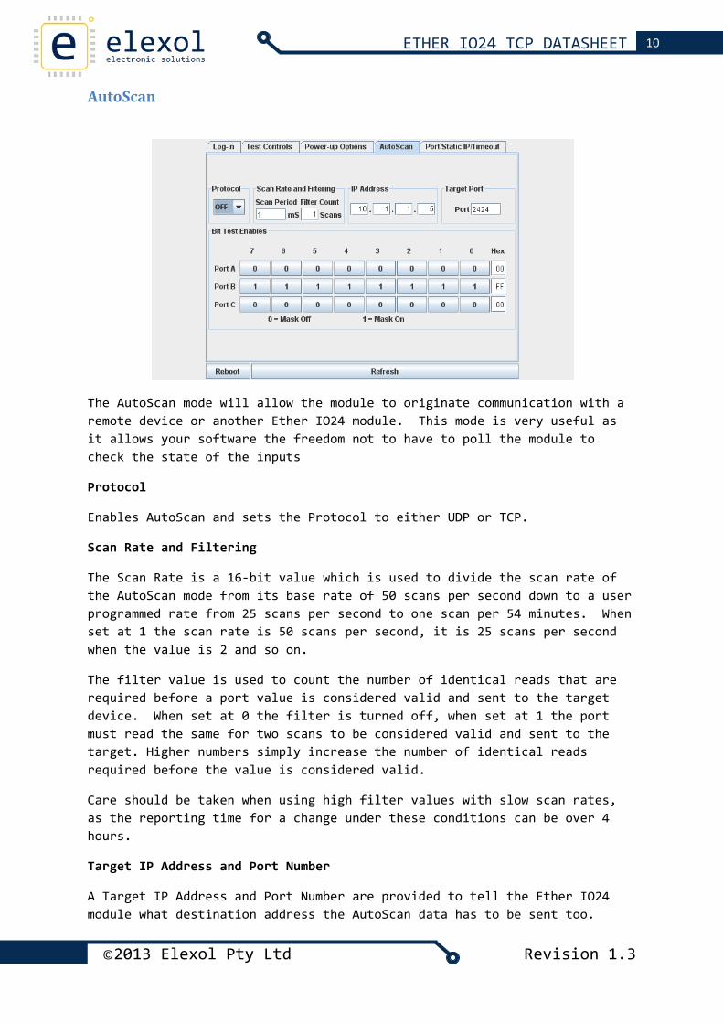
AutoScan
The AutoScan mode will allow the module to originate communication with a remote device or another Ether IO24 module. This mode is very useful as it allows your software the freedom not to have to poll the module to check the state of the inputs
Protocol
Enables AutoScan and sets the Protocol to either UDP or TCP.
Scan Rate and Filtering
The Scan Rate is a 16‐bit value which is used to divide the scan rate of the AutoScan mode from its base rate of 50 scans per second down to a user programmed rate from 25 scans per second to one scan per 54 minutes. When set at 1 the scan rate is 50 scans per second, it is 25 scans per second when the value is 2 and so on.
The filter value is used to count the number of identical reads that are required before a port value is considered valid and sent to the target device. When set at 0 the filter is turned off, when set at 1 the port must read the same for two scans to be considered valid and sent to the target. Higher numbers simply increase the number of identical reads required before the value is considered valid.
Care should be taken when using high filter values with slow scan rates, as the reporting time for a change under these conditions can be over 4 hours.
Target IP Address and Port Number
A Target IP Address and Port Number are provided to tell the Ether IO24 module what destination address the AutoScan data has to be sent too.
©2013 Elexol Pty Ltd Revision 1.3
11 ETHER IO24 TCP DATASHEET
Bit Test Enables
Mask bits are used to allow some of the input pins to toggle without generating messages from the module. Any input whose corresponding mask bit is low, is ignored by the AutoScan function.
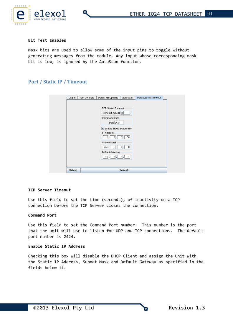
Port / Static IP / Timeout
TCP Server Timeout
Use this field to set the time (seconds), of inactivity on a TCP connection before the TCP Server closes the connection.
Command Port
Use this field to set the Command Port number. This number is the port that the unit will use to listen for UDP and TCP connections. The default port number is 2424.
Enable Static IP Address
Checking this box will disable the DHCP Client and assign the Unit with the Static IP Address, Subnet Mask and Default Gateway as specified in the fields below it.
©2013 Elexol Pty Ltd Revision 1.3
12 ETHER IO24 TCP DATASHEET
Command Interface (Via TCP and UDP Packets) The functions of the module are controlled by a command set that is sent via TCP or UDP packets. These TCP and UDP packets can be sent out from the PC via application software or from other Ether IO24 module if using AutoScan. This section will cover in detail the command summary followed by the Command set used by the Ether IO24 TCP module.
Command Summary The commands are displayed as followed:
• All commands are shown as ASCII characters, text in italics represent binary 1 byte values.
• Values that pertain to port Input, Output or control are shown as data,
• Values that pertain to address information are shown as address • Where a specific byte requires its hexadecimal value it is shown as
follows e.g. 0x55. • The spaces shown are only for clarity and no actual spaces are used in
commands sent to the module. • The I/O lines are accessed as 3 ports and each line is controlled by
its bit value within the data byte.
MODULE PORT CONFIGURATION
Each of the ports on the Ether IO24 TCP will need to be configured for the appropriate port mode configuration before sending commands to the unit. Care needs to be taken as different modes can affect the direction registers of the ports. The port mode can be set to either
• IO Mode This mode sets the Port to a standard Input/output port.
• SPI Mode This mode configures the Port to transmit and receive SPI data from a connected SPI peripheral device.
• I2C Mode (Pronounced “I‐squared‐C”) This mode configures the Port to transmit and receive I2C data from a connected I2C peripheral device.
The port mode can be changed via the web interface or by writing to the port mode EEPROM values for the configuration required. The default setting for the board will be IO MODE unless changed by the user.
©2013 Elexol Pty Ltd Revision 1.3
13 ETHER IO24 TCP DATASHEET
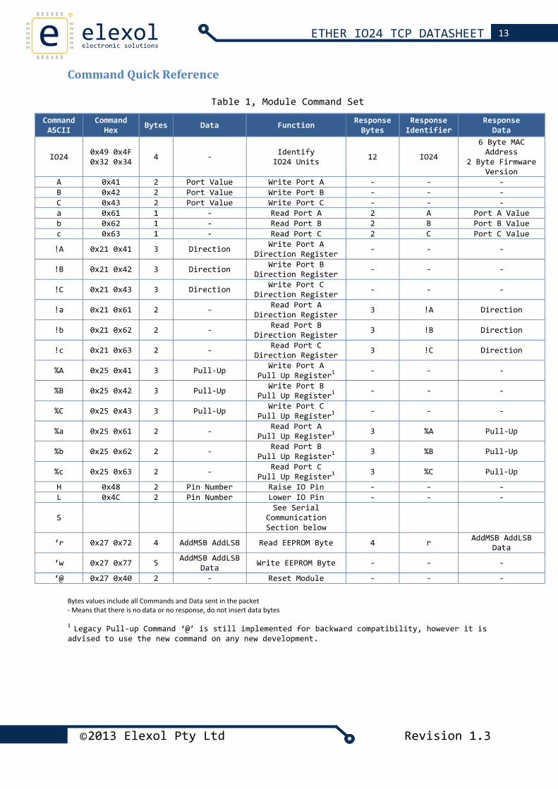
Command Quick Reference
Table 1, Module Command Set
Command ASCII
Command Hex Bytes Data Function Response
Bytes Response
Identifier Response
Data
IO24 0x49 0x4F 0x32 0x34 4 ‐ Identify
IO24 Units 12 IO24
6 Byte MAC Address
2 Byte Firmware Version
A 0x41 2 Port Value Write Port A ‐ ‐ ‐B 0x42 2 Port Value Write Port B ‐ ‐ ‐C 0x43 2 Port Value Write Port C ‐ ‐ ‐a 0x61 1 ‐ Read Port A 2 A Port A Valueb 0x62 1 ‐ Read Port B 2 B Port B Valuec 0x63 1 ‐ Read Port C 2 C Port C Value
!A 0x21 0x41 3 Direction Write Port A Direction Register ‐ ‐ ‐
!B 0x21 0x42 3 Direction Write Port B Direction Register ‐ ‐ ‐
!C 0x21 0x43 3 Direction Write Port C Direction Register ‐ ‐ ‐
!a 0x21 0x61 2 ‐ Read Port A Direction Register 3 !A Direction
!b 0x21 0x62 2 ‐ Read Port B Direction Register 3 !B Direction
!c 0x21 0x63 2 ‐ Read Port C Direction Register 3 !C Direction
%A 0x25 0x41 3 Pull‐Up Write Port A Pull Up Register1 ‐ ‐ ‐
%B 0x25 0x42 3 Pull‐Up Write Port B Pull Up Register1 ‐ ‐ ‐
%C 0x25 0x43 3 Pull‐Up Write Port C Pull Up Register1 ‐ ‐ ‐
%a 0x25 0x61 2 ‐ Read Port A Pull Up Register1 3 %A Pull‐Up
%b 0x25 0x62 2 ‐ Read Port B Pull Up Register1 3 %B Pull‐Up
%c 0x25 0x63 2 ‐ Read Port C Pull Up Register1 3 %C Pull‐Up
H 0x48 2 Pin Number Raise IO Pin ‐ ‐ ‐L 0x4C 2 Pin Number Lower IO Pin ‐ ‐ ‐
S See Serial
Communication Section below
‘r 0x27 0x72 4 AddMSB AddLSB Read EEPROM Byte 4 r AddMSB AddLSB Data
‘w 0x27 0x77 5 AddMSB AddLSB Data Write EEPROM Byte ‐ ‐ ‐
‘@ 0x27 0x40 2 ‐ Reset Module ‐ ‐ ‐
Bytes values include all Commands and Data sent in the packet ‐ Means that there is no data or no response, do not insert data bytes 1 Legacy Pull‐up Command ‘@’ is still implemented for backward compatibility, however it is advised to use the new command on any new development.
©2013 Elexol Pty Ltd Revision 1.3
14 ETHER IO24 TCP DATASHEET
Overview of Command Set
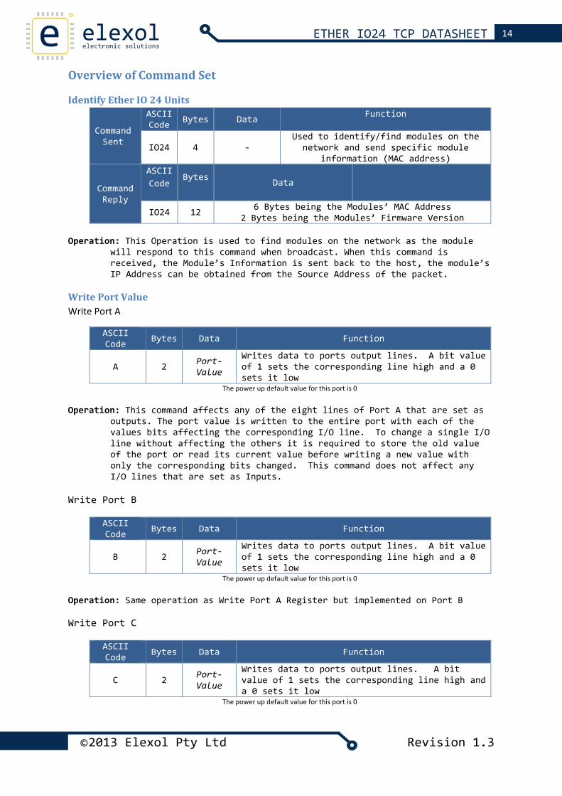
Identify Ether IO 24 Units
Command Sent
ASCII Code Bytes Data Function
IO24 4 ‐ Used to identify/find modules on the network and send specific module
information (MAC address)
Command Reply
ASCII Code
Bytes Data
IO24 12 6 Bytes being the Modules’ MAC Address 2 Bytes being the Modules’ Firmware Version
Operation: This Operation is used to find modules on the network as the module
will respond to this command when broadcast. When this command is received, the Module’s Information is sent back to the host, the module’s IP Address can be obtained from the Source Address of the packet.
Write Port Value Write Port A
ASCII Code Bytes Data Function
A 2 Port‐Value
Writes data to ports output lines. A bit value of 1 sets the corresponding line high and a 0 sets it low
The power up default value for this port is 0
Operation: This command affects any of the eight lines of Port A that are set as outputs. The port value is written to the entire port with each of the values bits affecting the corresponding I/O line. To change a single I/O line without affecting the others it is required to store the old value of the port or read its current value before writing a new value with only the corresponding bits changed. This command does not affect any I/O lines that are set as Inputs.
Write Port B
ASCII Code Bytes Data Function
B 2 Port‐Value
Writes data to ports output lines. A bit value of 1 sets the corresponding line high and a 0 sets it low
The power up default value for this port is 0
Operation: Same operation as Write Port A Register but implemented on Port B Write Port C
ASCII Code Bytes Data Function
C 2 Port‐Value
Writes data to ports output lines. A bit value of 1 sets the corresponding line high and a 0 sets it low
The power up default value for this port is 0
©2013 Elexol Pty Ltd Revision 1.3
15 ETHER IO24 TCP DATASHEET
©2013 Elexol Pty Ltd Revision 1.3
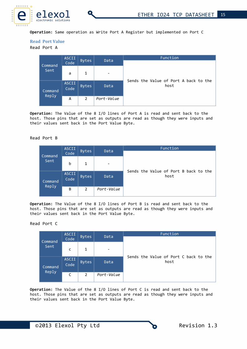
Operation: Same operation as Write Port A Register but implemented on Port C
Read Port Value Read Port A
Command Sent
ASCII Code Bytes Data
Function
Sends the Value of Port A back to the host
a
1 ‐
Command Reply
ASCII Code
Bytes Data
A 2 Port‐Value
Operation: The Value of the 8 I/O lines of Port A is read and sent back to the host. Those pins that are set as outputs are read as though they were inputs and their values sent back in the Port Value Byte.
Read Port B
Command Sent
ASCII Code Bytes Data
Function
Sends the Value of Port B back to the host
b
1 ‐
Command Reply
ASCII Code
Bytes Data
B 2 Port‐Value
Operation: The Value of the 8 I/O lines of Port B is read and sent back to the host. Those pins that are set as outputs are read as though they were inputs and their values sent back in the Port Value Byte. Read Port C
Command Sent
ASCII Code Bytes Data
Function
Sends the Value of Port C back to the host
c
1 ‐
Command Reply
ASCII Code
Bytes Data
C 2 Port‐Value
Operation: The Value of the 8 I/O lines of Port C is read and sent back to the host. Those pins that are set as outputs are read as though they were inputs and their values sent back in the Port Value Byte.
16 ETHER IO24 TCP DATASHEET
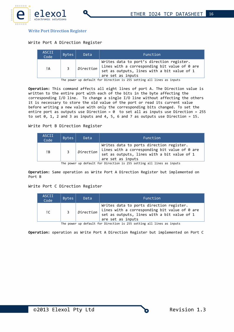
Write Port Direction Register Write Port A Direction Register
ASCII Code Bytes Data Function
!A 3 Direction
Writes data to port’s direction register. Lines with a corresponding bit value of 0 are set as outputs, lines with a bit value of 1 are set as inputs
The power up default for Direction is 255 setting all lines as inputs Operation: This command affects all eight lines of port A. The Direction value is written to the entire port with each of the bits in the byte affecting the corresponding I/O line. To change a single I/O line without affecting the others it is necessary to store the old value of the port or read its current value before writing a new value with only the corresponding bits changed. To set the entire port as outputs use Direction = 0 to set all as inputs use Direction = 255 to set 0, 1, 2 and 3 as inputs and 4, 5, 6 and 7 as outputs use Direction = 15. Write Port B Direction Register
ASCII Code Bytes Data Function
!B 3 Direction
Writes data to ports direction register. Lines with a corresponding bit value of 0 are set as outputs, lines with a bit value of 1 are set as inputs
The power up default for Direction is 255 setting all lines as inputs Operation: Same operation as Write Port A Direction Register but implemented on Port B Write Port C Direction Register
ASCII Code Bytes Data Function
!C 3 Direction
Writes data to ports direction register. Lines with a corresponding bit value of 0 are set as outputs, lines with a bit value of 1 are set as inputs
The power up default for Direction is 255 setting all lines as inputs Operation: operation as Write Port A Direction Register but implemented on Port C
©2013 Elexol Pty Ltd Revision 1.3
17 ETHER IO24 TCP DATASHEET
©2013 Elexol Pty Ltd Revision 1.3
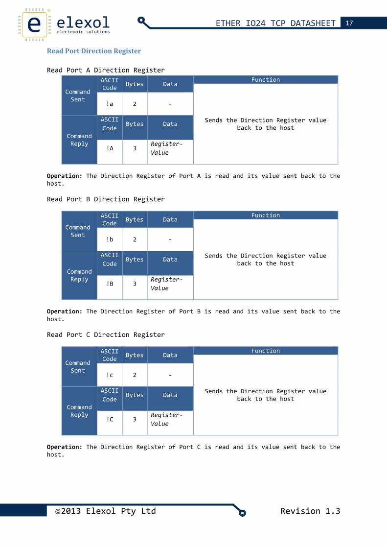
Read Port Direction Register Read Port A Direction Register
Command Sent
ASCII Code Bytes Data
Function
Sends the Direction Register value back to the host
!a
2 ‐
Command Reply
ASCII Code
Bytes Data
!A 3 Register‐Value
Operation: The Direction Register of Port A is read and its value sent back to the host. Read Port B Direction Register
Command Sent
ASCII Code Bytes Data
Function
Sends the Direction Register value back to the host
!b
2 ‐
Command Reply
ASCII Code
Bytes Data
!B 3 Register‐Value
Operation: The Direction Register of Port B is read and its value sent back to the host. Read Port C Direction Register
Command Sent
ASCII Code Bytes Data
Function
Sends the Direction Register value back to the host
!c
2 ‐
Command Reply
ASCII Code
Bytes Data
!C 3 Register‐Value
Operation: The Direction Register of Port C is read and its value sent back to the host.
18 ETHER IO24 TCP DATASHEET
©2013 Elexol Pty Ltd Revision 1.3
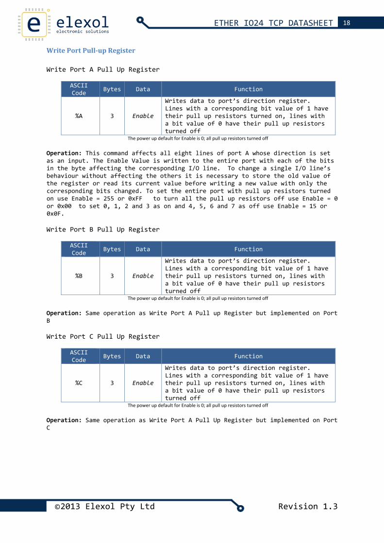
Write Port Pull‐up Register Write Port A Pull Up Register
ASCII Code Bytes Data Function
%A 3 Enable
Writes data to port’s direction register. Lines with a corresponding bit value of 1 have their pull up resistors turned on, lines with a bit value of 0 have their pull up resistors turned off
The power up default for Enable is 0; all pull up resistors turned off Operation: This command affects all eight lines of port A whose direction is set as an input. The Enable Value is written to the entire port with each of the bits in the byte affecting the corresponding I/O line. To change a single I/O line’s behaviour without affecting the others it is necessary to store the old value of the register or read its current value before writing a new value with only the corresponding bits changed. To set the entire port with pull up resistors turned on use Enable = 255 or 0xFF to turn all the pull up resistors off use Enable = 0 or 0x00 to set 0, 1, 2 and 3 as on and 4, 5, 6 and 7 as off use Enable = 15 or 0x0F. Write Port B Pull Up Register
ASCII Code Bytes Data Function
%B 3 Enable
Writes data to port’s direction register. Lines with a corresponding bit value of 1 have their pull up resistors turned on, lines with a bit value of 0 have their pull up resistors turned off
The power up default for Enable is 0; all pull up resistors turned off Operation: Same operation as Write Port A Pull up Register but implemented on Port B Write Port C Pull Up Register
ASCII Code Bytes Data Function
%C 3 Enable
Writes data to port’s direction register. Lines with a corresponding bit value of 1 have their pull up resistors turned on, lines with a bit value of 0 have their pull up resistors turned off
The power up default for Enable is 0; all pull up resistors turned off Operation: Same operation as Write Port A Pull Up Register but implemented on Port C
19 ETHER IO24 TCP DATASHEET
©2013 Elexol Pty Ltd Revision 1.3
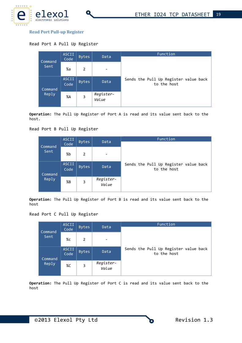
Read Port Pull‐up Register Read Port A Pull Up Register
Command Sent
ASCII Code Bytes Data
Function
Sends the Pull Up Register value back to the host
%a
2 ‐
Command Reply
ASCII Code
Bytes Data
%A 3 Register‐Value
Operation: The Pull Up Register of Port A is read and its value sent back to the host. Read Port B Pull Up Register
Command Sent
ASCII Code Bytes Data
Function
Sends the Pull Up Register value back to the host
%b
2 ‐
Command Reply
ASCII Code
Bytes Data
%B 3 Register‐
Value
Operation: The Pull Up Register of Port B is read and its value sent back to the host Read Port C Pull Up Register
Command Sent
ASCII Code Bytes Data
Function
Sends the Pull Up Register value back to the host
%c
2 ‐
Command Reply
ASCII Code Bytes Data
%C 3 Register‐
Value
Operation: The Pull Up Register of Port C is read and its value sent back to the host
20 ETHER IO24 TCP DATASHEET
©2013 Elexol Pty Ltd Revision 1.3
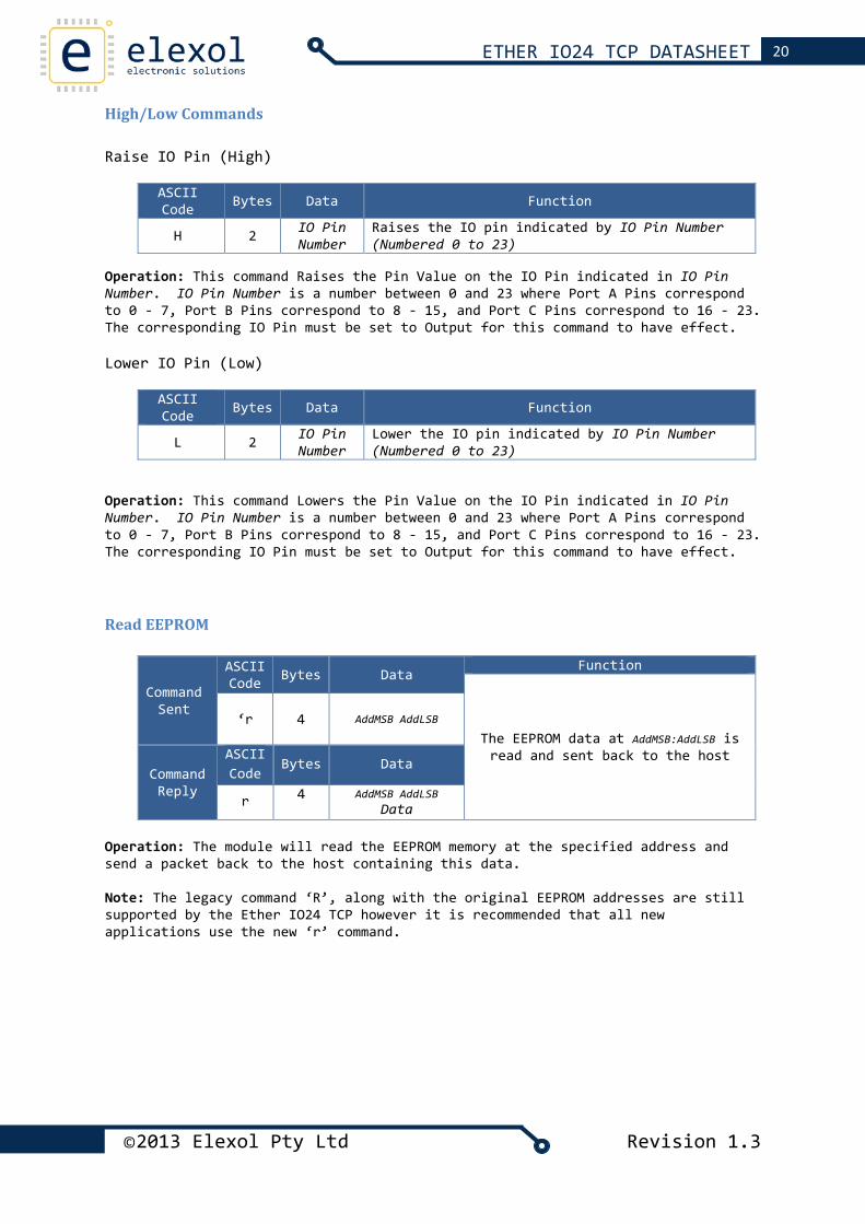
High/Low Commands Raise IO Pin (High)
ASCII Code Bytes Data Function
H 2 IO Pin Number
Raises the IO pin indicated by IO Pin Number(Numbered 0 to 23)
Operation: This command Raises the Pin Value on the IO Pin indicated in IO Pin Number. IO Pin Number is a number between 0 and 23 where Port A Pins correspond to 0 ‐ 7, Port B Pins correspond to 8 ‐ 15, and Port C Pins correspond to 16 ‐ 23. The corresponding IO Pin must be set to Output for this command to have effect. Lower IO Pin (Low)
ASCII Code Bytes Data Function
L 2 IO Pin Number
Lower the IO pin indicated by IO Pin Number(Numbered 0 to 23)
Operation: This command Lowers the Pin Value on the IO Pin indicated in IO Pin Number. IO Pin Number is a number between 0 and 23 where Port A Pins correspond to 0 ‐ 7, Port B Pins correspond to 8 ‐ 15, and Port C Pins correspond to 16 ‐ 23. The corresponding IO Pin must be set to Output for this command to have effect.
Read EEPROM
Command Sent
ASCII Code Bytes Data
Function
The EEPROM data at AddMSB:AddLSB is read and sent back to the host
‘r
4 AddMSB AddLSB
Command Reply
ASCII Code
Bytes Data
r 4 AddMSB AddLSBData
Operation: The module will read the EEPROM memory at the specified address and send a packet back to the host containing this data. Note: The legacy command ‘R’, along with the original EEPROM addresses are still supported by the Ether IO24 TCP however it is recommended that all new applications use the new ‘r’ command.
21 ETHER IO24 TCP DATASHEET
©2013 Elexol Pty Ltd Revision 1.3
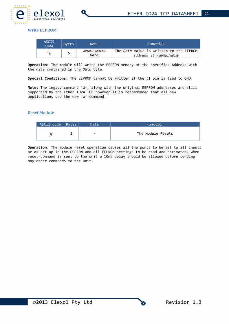
Write EEPROM
ASCII Code Bytes Data Function
‘w 5 AddMSB AddLSB
Data The Data value is written to the EEPROM
address at AddMSB:AddLSB
Operation: The module will write the EEPROM memory at the specified Address with the data contained in the Data byte. Special Conditions: The EEPROM cannot be written if the J1 pin is tied to GND. Note: The legacy command ‘W’, along with the original EEPROM addresses are still supported by the Ether IO24 TCP however it is recommended that all new applications use the new ‘w’ command.
Reset Module
ASCII Code Bytes Data Function
‘@
2 ‐ The Module Resets
Operation: The module reset operation causes all the ports to be set to all inputs or as set up in the EEPROM and all EEPROM settings to be read and activated. When reset command is sent to the unit a 10ms delay should be allowed before sending any other commands to the unit.
22 ETHER IO24 TCP DATASHEET
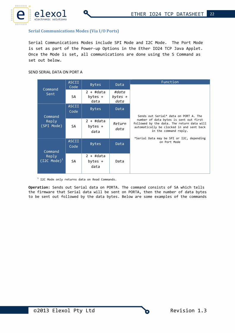
Serial Communications Modes (Via I/O Ports) Serial Communications Modes include SPI Mode and I2C Mode. The Port Mode is set as part of the Power‐up Options in the Ether IO24 TCP Java Applet. Once the Mode is set, all communications are done using the S Command as set out below. SEND SERIAL DATA ON PORT A
Command Sent
ASCII Code Bytes Data
Function
Sends out Serial* data on PORT A. The number of data bytes is sent out first
followed by the data. The return data will automatically be clocked in and sent back
in the command reply.
*Serial Data may be SPI or I2C, depending on Port Mode
SA 2 + #data bytes + data
#data bytes + data
Command Reply
(SPI Mode)
ASCII Code
Bytes Data
SA 2 + #data bytes + data
Return data
Command Reply
(I2C Mode)1
ASCII Code
Bytes Data
SA 2 + #data bytes + data
Data
1 I2C Mode only returns data on Read Commands. Operation: Sends out Serial data on PORTA. The command consists of SA which tells the firmware that Serial data will be sent on PORTA, then the number of data bytes to be sent out followed by the data bytes. Below are some examples of the commands
©2013 Elexol Pty Ltd Revision 1.3
23 ETHER IO24 TCP DATASHEET
©2013 Elexol Pty Ltd Revision 1.3
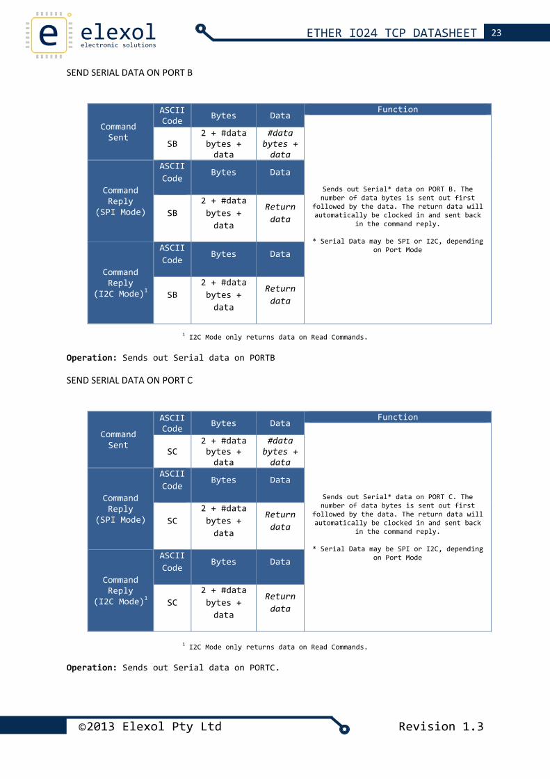
SEND SERIAL DATA ON PORT B
Command Sent
ASCII Code Bytes Data
Function
Sends out Serial* data on PORT B. The number of data bytes is sent out first
followed by the data. The return data will automatically be clocked in and sent back
in the command reply.
* Serial Data may be SPI or I2C, depending on Port Mode
SB 2 + #databytes + data
#data bytes + data
Command Reply
(SPI Mode)
ASCII Code
Bytes Data
SB 2 + #data bytes + data
Return data
Command Reply
(I2C Mode)1
ASCII Code
Bytes Data
SB 2 + #data bytes + data
Return data
1 I2C Mode only returns data on Read Commands. Operation: Sends out Serial data on PORTB
SEND SERIAL DATA ON PORT C
Command Sent
ASCII Code Bytes Data
Function
Sends out Serial* data on PORT C. The number of data bytes is sent out first
followed by the data. The return data will automatically be clocked in and sent back
in the command reply.
* Serial Data may be SPI or I2C, depending on Port Mode
SC 2 + #databytes + data
#data bytes + data
Command Reply
(SPI Mode)
ASCII Code
Bytes Data
SC 2 + #data bytes + data
Return data
Command Reply
(I2C Mode)1
ASCII Code
Bytes Data
SC 2 + #data bytes + data
Return data
1 I2C Mode only returns data on Read Commands. Operation: Sends out Serial data on PORTC.
24 ETHER IO24 TCP DATASHEET
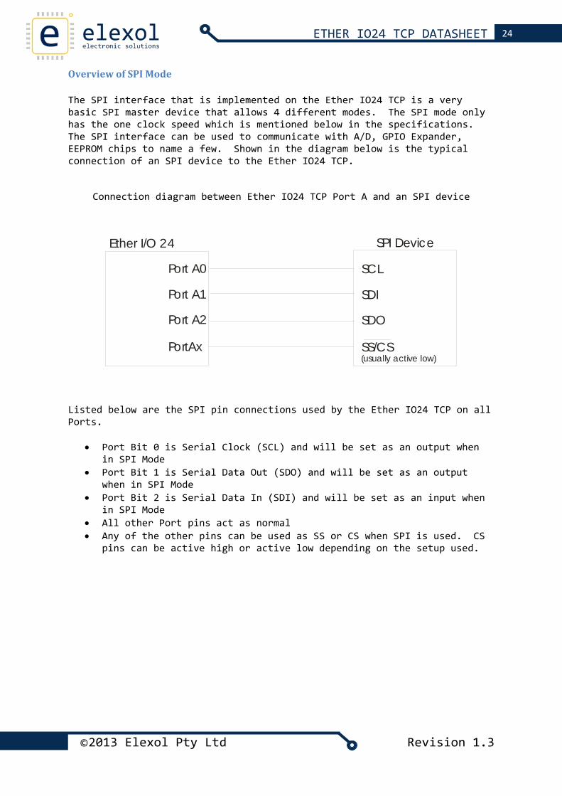
Overview of SPI Mode The SPI interface that is implemented on the Ether IO24 TCP is a very basic SPI master device that allows 4 different modes. The SPI mode only has the one clock speed which is mentioned below in the specifications. The SPI interface can be used to communicate with A/D, GPIO Expander, EEPROM chips to name a few. Shown in the diagram below is the typical connection of an SPI device to the Ether IO24 TCP.
Connection diagram between Ether IO24 TCP Port A and an SPI device
Port A0
Port A1
Port A2
PortAx
SPI DeviceEther I/O 24
SCL
SDI
SDO
SS/CS(usually active low)
Listed below are the SPI pin connections used by the Ether IO24 TCP on all Ports.
• Port Bit 0 is Serial Clock (SCL) and will be set as an output when in SPI Mode
• Port Bit 1 is Serial Data Out (SDO) and will be set as an output when in SPI Mode
• Port Bit 2 is Serial Data In (SDI) and will be set as an input when in SPI Mode
• All other Port pins act as normal • Any of the other pins can be used as SS or CS when SPI is used. CS
pins can be active high or active low depending on the setup used.
©2013 Elexol Pty Ltd Revision 1.3
25 ETHER IO24 TCP DATASHEET
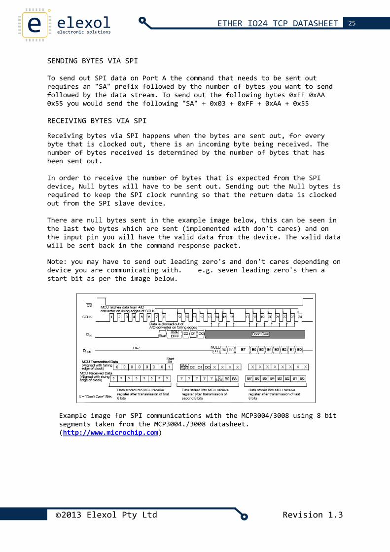
SENDING BYTES VIA SPI To send out SPI data on Port A the command that needs to be sent out requires an "SA" prefix followed by the number of bytes you want to send followed by the data stream. To send out the following bytes 0xFF 0xAA 0x55 you would send the following "SA" + 0x03 + 0xFF + 0xAA + 0x55 RECEIVING BYTES VIA SPI Receiving bytes via SPI happens when the bytes are sent out, for every byte that is clocked out, there is an incoming byte being received. The number of bytes received is determined by the number of bytes that has been sent out. In order to receive the number of bytes that is expected from the SPI device, Null bytes will have to be sent out. Sending out the Null bytes is required to keep the SPI clock running so that the return data is clocked out from the SPI slave device. There are null bytes sent in the example image below, this can be seen in the last two bytes which are sent (implemented with don't cares) and on the input pin you will have the valid data from the device. The valid data will be sent back in the command response packet. Note: you may have to send out leading zero's and don't cares depending on device you are communicating with. e.g. seven leading zero's then a start bit as per the image below.
Example image for SPI communications with the MCP3004/3008 using 8 bit segments taken from the MCP3004./3008 datasheet. (http://www.microchip.com)
©2013 Elexol Pty Ltd Revision 1.3
26 ETHER IO24 TCP DATASHEET
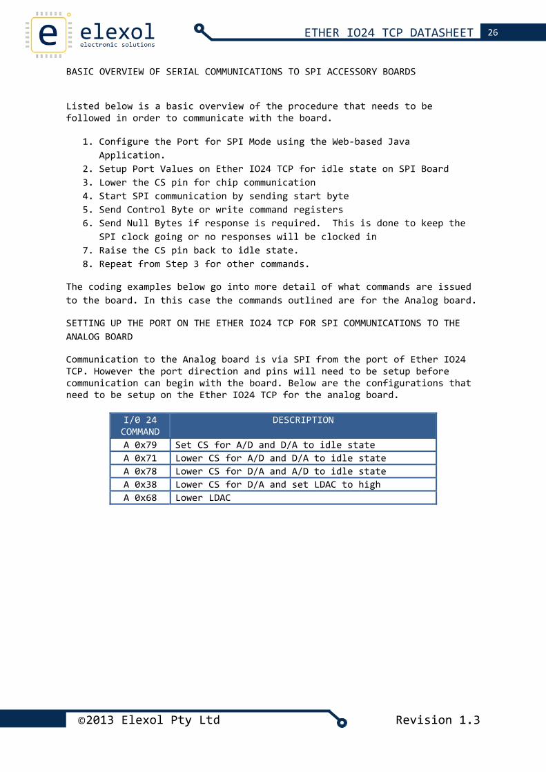
BASIC OVERVIEW OF SERIAL COMMUNICATIONS TO SPI ACCESSORY BOARDS
Listed below is a basic overview of the procedure that needs to be followed in order to communicate with the board.
1. Configure the Port for SPI Mode using the Web‐based Java Application.
2. Setup Port Values on Ether IO24 TCP for idle state on SPI Board 3. Lower the CS pin for chip communication 4. Start SPI communication by sending start byte 5. Send Control Byte or write command registers 6. Send Null Bytes if response is required. This is done to keep the
SPI clock going or no responses will be clocked in 7. Raise the CS pin back to idle state. 8. Repeat from Step 3 for other commands.
The coding examples below go into more detail of what commands are issued to the board. In this case the commands outlined are for the Analog board.
SETTING UP THE PORT ON THE ETHER IO24 TCP FOR SPI COMMUNICATIONS TO THE ANALOG BOARD
Communication to the Analog board is via SPI from the port of Ether IO24 TCP. However the port direction and pins will need to be setup before communication can begin with the board. Below are the configurations that need to be setup on the Ether IO24 TCP for the analog board.
I/0 24 COMMAND
DESCRIPTION
A 0x79 Set CS for A/D and D/A to idle state A 0x71 Lower CS for A/D and D/A to idle state A 0x78 Lower CS for D/A and A/D to idle state A 0x38 Lower CS for D/A and set LDAC to high A 0x68 Lower LDAC
©2013 Elexol Pty Ltd Revision 1.3
27 ETHER IO24 TCP DATASHEET
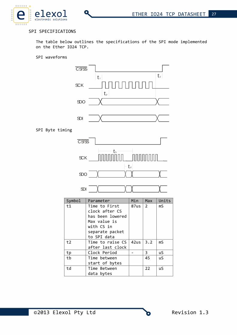
SPI SPECIFICATIONS The table below outlines the specifications of the SPI mode implemented on the Ether IO24 TCP. SPI waveforms
CS/SS
SCK
SDO
SDI
tp
t1 t2
SPI Byte timing
CS/SS
SCK
SDO
SDI
td
tb
Symbol Parameter Min Max Units t1 Time to First
clock after CS has been lowered Max value is with CS in separate packet to SPI data
87us 2 mS
t2 Time to raise CS after last clock
42us 3.2 mS
tp Clock Period ‐ 3 uS tb Time between
start of bytes 45 uS
td Time Between data bytes
22 uS
©2013 Elexol Pty Ltd Revision 1.3
28 ETHER IO24 TCP DATASHEET
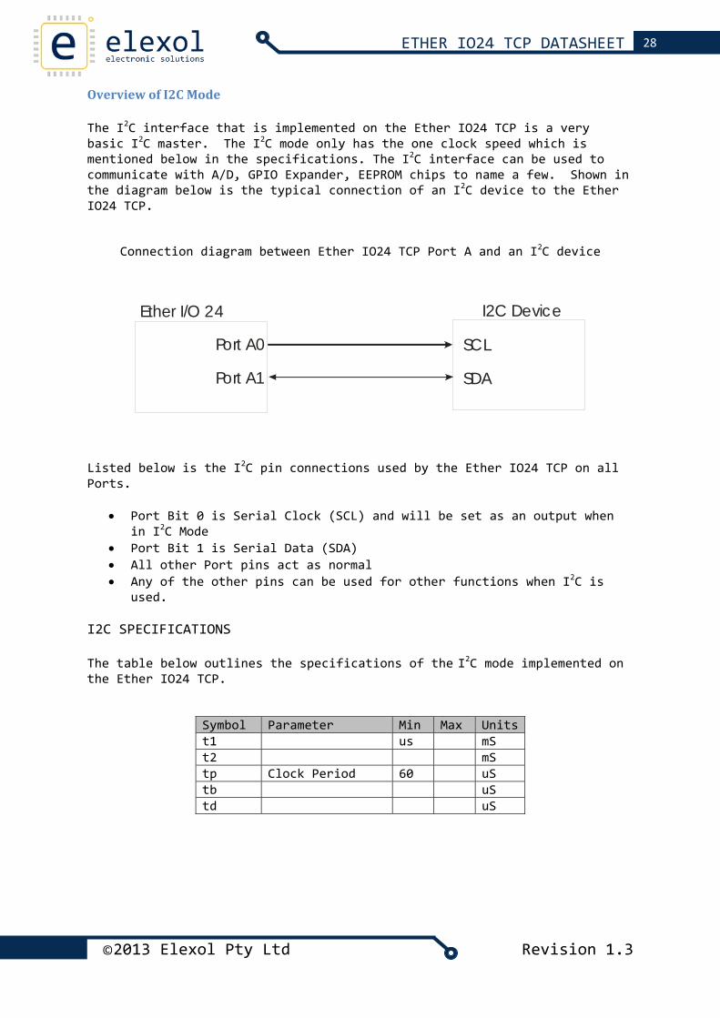
Overview of I2C Mode The I2C interface that is implemented on the Ether IO24 TCP is a very basic I2C master. The I2C mode only has the one clock speed which is mentioned below in the specifications. The I2C interface can be used to communicate with A/D, GPIO Expander, EEPROM chips to name a few. Shown in the diagram below is the typical connection of an I2C device to the Ether IO24 TCP.
Connection diagram between Ether IO24 TCP Port A and an I2C device
Port A0
Port A1
I2C DeviceEther I/O 24
SCL
SDA
Listed below is the I2C pin connections used by the Ether IO24 TCP on all Ports.
• Port Bit 0 is Serial Clock (SCL) and will be set as an output when in I2C Mode
• Port Bit 1 is Serial Data (SDA) • All other Port pins act as normal • Any of the other pins can be used for other functions when I2C is
used.
I2C SPECIFICATIONS The table below outlines the specifications of the I2C mode implemented on the Ether IO24 TCP.
Symbol Parameter Min Max Units t1 us mS t2 mS tp Clock Period 60 uS tb uS td uS
©2013 Elexol Pty Ltd Revision 1.3
29 ETHER IO24 TCP DATASHEET
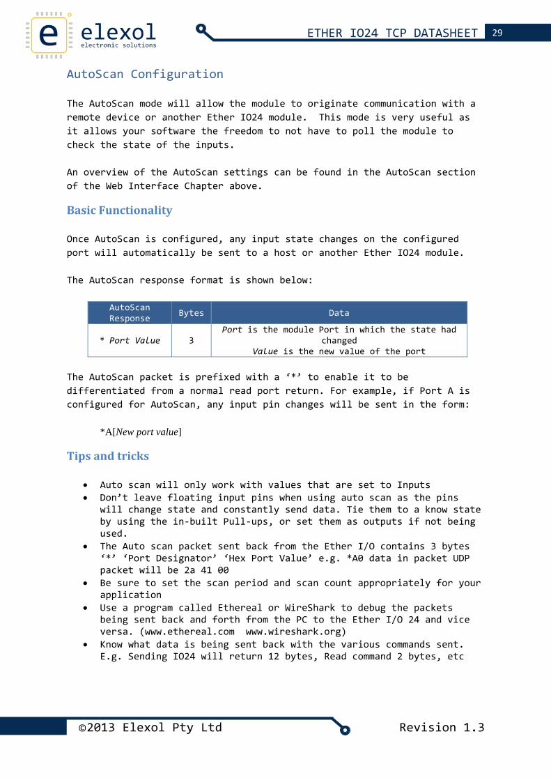
AutoScan Configuration The AutoScan mode will allow the module to originate communication with a remote device or another Ether IO24 module. This mode is very useful as it allows your software the freedom to not have to poll the module to check the state of the inputs. An overview of the AutoScan settings can be found in the AutoScan section of the Web Interface Chapter above.
Basic Functionality Once AutoScan is configured, any input state changes on the configured port will automatically be sent to a host or another Ether IO24 module. The AutoScan response format is shown below:
AutoScan Response Bytes Data
* Port Value 3 Port is the module Port in which the state had
changed Value is the new value of the port
The AutoScan packet is prefixed with a ‘*’ to enable it to be differentiated from a normal read port return. For example, if Port A is configured for AutoScan, any input pin changes will be sent in the form:
*A[New port value]
Tips and tricks
• Auto scan will only work with values that are set to Inputs • Don’t leave floating input pins when using auto scan as the pins
will change state and constantly send data. Tie them to a know state by using the in‐built Pull‐ups, or set them as outputs if not being used.
• The Auto scan packet sent back from the Ether I/O contains 3 bytes ‘*’ ‘Port Designator’ ‘Hex Port Value’ e.g. *A0 data in packet UDP packet will be 2a 41 00
• Be sure to set the scan period and scan count appropriately for your application
• Use a program called Ethereal or WireShark to debug the packets being sent back and forth from the PC to the Ether I/O 24 and vice versa. (www.ethereal.com www.wireshark.org)
• Know what data is being sent back with the various commands sent. E.g. Sending IO24 will return 12 bytes, Read command 2 bytes, etc
©2013 Elexol Pty Ltd Revision 1.3
30 ETHER IO24 TCP DATASHEET
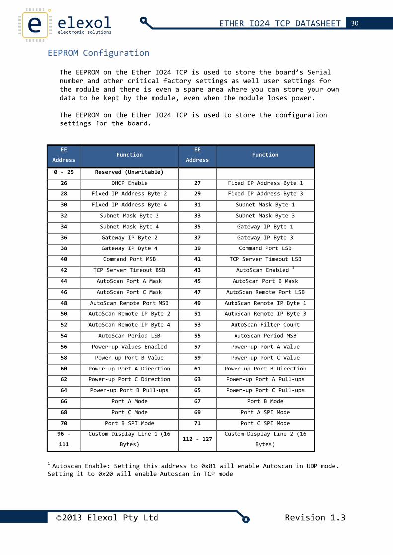
EEPROM Configuration The EEPROM on the Ether IO24 TCP is used to store the board’s Serial number and other critical factory settings as well user settings for the module and there is even a spare area where you can store your own data to be kept by the module, even when the module loses power. The EEPROM on the Ether IO24 TCP is used to store the configuration settings for the board.
EE
Address Function
EE
Address Function
0 ‐ 25 Reserved (Unwritable)
26 DHCP Enable 27 Fixed IP Address Byte 1
28 Fixed IP Address Byte 2 29 Fixed IP Address Byte 3
30 Fixed IP Address Byte 4 31 Subnet Mask Byte 1
32 Subnet Mask Byte 2 33 Subnet Mask Byte 3
34 Subnet Mask Byte 4 35 Gateway IP Byte 1
36 Gateway IP Byte 2 37 Gateway IP Byte 3
38 Gateway IP Byte 4 39 Command Port LSB
40 Command Port MSB 41 TCP Server Timeout LSB
42 TCP Server Timeout BSB 43 AutoScan Enabled 1
44 AutoScan Port A Mask 45 AutoScan Port B Mask
46 AutoScan Port C Mask 47 AutoScan Remote Port LSB
48 AutoScan Remote Port MSB 49 AutoScan Remote IP Byte 1
50 AutoScan Remote IP Byte 2 51 AutoScan Remote IP Byte 3
52 AutoScan Remote IP Byte 4 53 AutoScan Filter Count
54 AutoScan Period LSB 55 AutoScan Period MSB
56 Power‐up Values Enabled 57 Power‐up Port A Value
58 Power‐up Port B Value 59 Power‐up Port C Value
60 Power‐up Port A Direction 61 Power‐up Port B Direction
62 Power‐up Port C Direction 63 Power‐up Port A Pull‐ups
64 Power‐up Port B Pull‐ups 65 Power‐up Port C Pull‐ups
66 Port A Mode 67 Port B Mode
68 Port C Mode 69 Port A SPI Mode
70 Port B SPI Mode 71 Port C SPI Mode
96 ‐
111
Custom Display Line 1 (16
Bytes) 112 ‐ 127
Custom Display Line 2 (16
Bytes)
1 Autoscan Enable: Setting this address to 0x01 will enable Autoscan in UDP mode. Setting it to 0x20 will enable Autoscan in TCP mode
©2013 Elexol Pty Ltd Revision 1.3
31 ETHER IO24 TCP DATASHEET
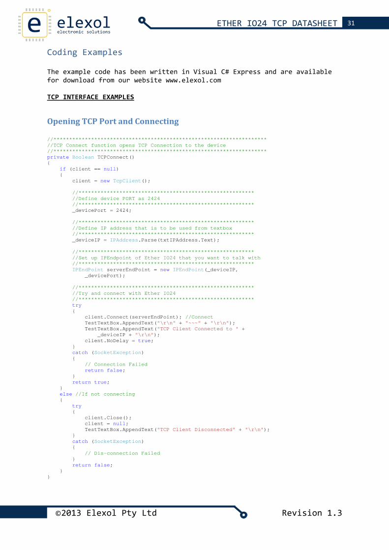
Coding Examples The example code has been written in Visual C# Express and are available for download from our website www.elexol.com TCP INTERFACE EXAMPLES
Opening TCP Port and Connecting //******************************************************************** //TCP Connect function opens TCP Connection to the device //******************************************************************** private Boolean TCPConnect() { if (client == null) { client = new TcpClient(); //******************************************************** //Define device PORT as 2424 //******************************************************** _devicePort = 2424; //******************************************************** //Define IP address that is to be used from textbox //******************************************************** _deviceIP = IPAddress.Parse(txtIPAddress.Text); //******************************************************** //Set up IPEndpoint of Ether IO24 that you want to talk with //******************************************************** IPEndPoint serverEndPoint = new IPEndPoint(_deviceIP, _devicePort); //******************************************************** //Try and connect with Ether IO24 //******************************************************** try { client.Connect(serverEndPoint); //Connect TestTextBox.AppendText("\r\n" + "~~~" + "\r\n"); TestTextBox.AppendText("TCP Client Connected to " + _deviceIP + "\r\n"); client.NoDelay = true; } catch (SocketException) { // Connection Failed return false; } return true; } else //If not connecting { try { client.Close(); client = null; TestTextBox.AppendText("TCP Client Disconnected" + "\r\n"); } catch (SocketException) { // Dis-connection Failed } return false; } }
©2013 Elexol Pty Ltd Revision 1.3
32 ETHER IO24 TCP DATASHEET
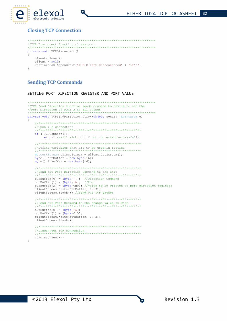
Closing TCP Connection //******************************************************************** //TCP Disconnect function closes port //******************************************************************** private void TCPDisconnect() { client.Close(); client = null; TestTextBox.AppendText("TCP Client Disconnected" + "\r\n"); }
Sending TCP Commands SETTING PORT DIRECTION REGISTER AND PORT VALUE //******************************************************************** //TCP Send Direction function sends command to device to set the //Port Direction of PORT A to all output //******************************************************************** private void TCPSendDirection_Click(object sender, EventArgs e) { //******************************************************** //Open TCP Connection //******************************************************** if (!TCPConnect()) return; //will kick out if not connected successfully //******************************************************** //Define variables that are to be used in routine //******************************************************** NetworkStream clientStream = client.GetStream(); byte[] outBuffer = new byte[16]; byte[] inBuffer = new byte[16]; //******************************************************** //Send out Port Direction Command to the unit //******************************************************** outBuffer[0] = (byte)'!'; //Direction Command outBuffer[1] = (byte)'A'; //Port outBuffer[2] = (byte)0x00; //Value to be written to port direction register clientStream.Write(outBuffer, 0, 3); clientStream.Flush(); //Send out TCP packet //******************************************************** //Send out Port Command to the change value on Port //******************************************************** outBuffer[0] = (byte)'A'; outBuffer[1] = (byte)0x55; clientStream.Write(outBuffer, 0, 2); clientStream.Flush(); //******************************************************** //Disconnect TCP connection //******************************************************** TCPDisconnect(); }
©2013 Elexol Pty Ltd Revision 1.3
33 ETHER IO24 TCP DATASHEET
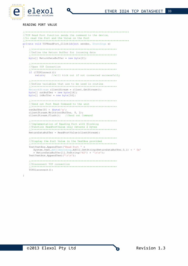
READING PORT VALUE //******************************************************************** //TCP Read Port function sends the command to the device, //to read the Port and the Value on the Port //******************************************************************** private void TCPReadPort_Click(object sender, EventArgs e) { //******************************************************** //Define the Return Buffer for incoming data //******************************************************** byte[] ReturnDataBuffer = new byte[2]; //******************************************************** //Open TCP Connection //******************************************************** if (!TCPConnect()) return; //will kick out if not connected successfully //******************************************************** //Define variables that are to be used in routine //******************************************************** NetworkStream clientStream = client.GetStream(); byte[] outBuffer = new byte[16]; byte[] inBuffer = new byte[16]; //******************************************************** //Send out Port Read Command to the unit //******************************************************** outBuffer[0] = (byte)'a'; clientStream.Write(outBuffer, 0, 1); clientStream.Flush(); //Send out Command //******************************************************** //Implementation of Reading Port with Blocking //Function ReadPortValue only returns 2 bytes //******************************************************** ReturnDataBuffer = ReadPortValue(clientStream); //******************************************************** //Display the Port Value in the TextBox provided //******************************************************** TestTextBox.AppendText("Read Port " + System.Text.ASCIIEncoding.ASCII.GetString(ReturnDataBuffer,0,1) + " 0x" + ReturnDataBuffer[1].ToString("X2") + "\r\n"); TestTextBox.AppendText("\r\n"); //******************************************************** //Disconnect TCP connection //******************************************************** TCPDisconnect(); }
©2013 Elexol Pty Ltd Revision 1.3
34 ETHER IO24 TCP DATASHEET
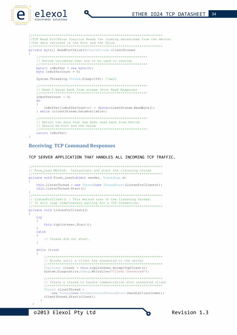
//******************************************************************** //TCP Read PortValue function Reads the icoming datastream from the device, //the data returned is the Port and the Value //******************************************************************** private byte[] ReadPortValue(NetworkStream clientStream) { //******************************************************** // Define variables that are to be used in routine //******************************************************** byte[] inBuffer = new byte[2]; byte inBufferCount = 0; System.Threading.Thread.Sleep(100); //wait //******************************************************** // Read 2 bytes back from stream (Port Read Response) //******************************************************** inBufferCount = 0; do { inBuffer[inBufferCount++] = (byte)clientStream.ReadByte(); } while (clientStream.DataAvailable); //******************************************************** // Return the data that has been read back from Device // Should be Port and the Value //******************************************************** return inBuffer; }
Receiving TCP Command Responses TCP SERVER APPLICATION THAT HANDLES ALL INCOMING TCP TRAFFIC. //******************************************************************** // Form_Load Method: Instantiate and start the listening thread //******************************************************************** private void Form1_Load(object sender, EventArgs e) { this.listenThread = new Thread(new ThreadStart(ListenForClients)); this.listenThread.Start(); } //******************************************************************** // ListenForClient() : This method runs in the listening thread. // It will loop indefinately waiting for a TCP Connection. //******************************************************************** private void ListenForClients() { try { this.tcpListener.Start(); } catch { // Thread did not start. } while (true) { //************************************************************ // Blocks until a client has connected to the server //************************************************************ TcpClient client = this.tcpListener.AcceptTcpClient(); System.Diagnostics.Debug.WriteLine("Client Connected"); //************************************************************ // Create a thread to handle communication with connected client //************************************************************ Thread clientThread = new Thread(new ParameterizedThreadStart(HandleClientComm)); clientThread.Start(client); } }
©2013 Elexol Pty Ltd Revision 1.3
35 ETHER IO24 TCP DATASHEET
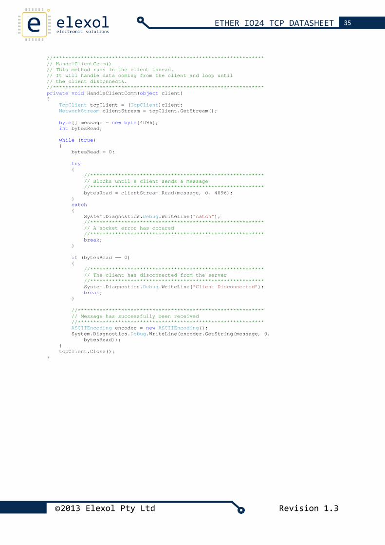
//******************************************************************** // HandelClientComm() // This method runs in the client thread. // It will handle data coming from the client and loop until // the client disconnects. //******************************************************************** private void HandleClientComm(object client) { TcpClient tcpClient = (TcpClient)client; NetworkStream clientStream = tcpClient.GetStream(); byte[] message = new byte[4096]; int bytesRead; while (true) { bytesRead = 0; try { //******************************************************** // Blocks until a client sends a message //******************************************************** bytesRead = clientStream.Read(message, 0, 4096); } catch { System.Diagnostics.Debug.WriteLine("catch"); //******************************************************** // A socket error has occured //******************************************************** break; } if (bytesRead == 0) { //******************************************************** // The client has disconnected from the server //******************************************************** System.Diagnostics.Debug.WriteLine("Client Disconnected"); break; } //************************************************************ // Message has successfully been received //************************************************************ ASCIIEncoding encoder = new ASCIIEncoding(); System.Diagnostics.Debug.WriteLine(encoder.GetString(message, 0, bytesRead)); } tcpClient.Close(); }
©2013 Elexol Pty Ltd Revision 1.3
36 ETHER IO24 TCP DATASHEET
UDP INTERFACE EXAMPLES
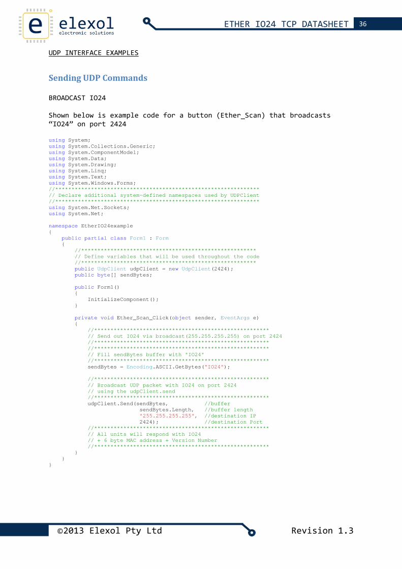
Sending UDP Commands BROADCAST IO24 Shown below is example code for a button (Ether_Scan) that broadcasts “IO24” on port 2424 using System; using System.Collections.Generic; using System.ComponentModel; using System.Data; using System.Drawing; using System.Linq; using System.Text; using System.Windows.Forms; //*************************************************************** // Declare additional system-defined namespaces used by UDPClient //*************************************************************** using System.Net.Sockets; using System.Net; namespace EtherIO24example { public partial class Form1 : Form { //****************************************************** // Define variables that will be used throughout the code //****************************************************** public UdpClient udpClient = new UdpClient(2424); public byte[] sendBytes; public Form1() { InitializeComponent(); } private void Ether_Scan_Click(object sender, EventArgs e) { //****************************************************** // Send out IO24 via broadcast(255.255.255.255) on port 2424 //****************************************************** //****************************************************** // Fill sendBytes buffer with "IO24" //****************************************************** sendBytes = Encoding.ASCII.GetBytes("IO24"); //****************************************************** // Broadcast UDP packet with IO24 on port 2424 // using the udpClient.send //****************************************************** udpClient.Send(sendBytes, //buffer sendBytes.Length, //buffer length "255.255.255.255", //destination IP 2424); //destination Port //****************************************************** // All units will respond with IO24 // + 6 byte MAC address + Version Number //****************************************************** } } }
©2013 Elexol Pty Ltd Revision 1.3
37 ETHER IO24 TCP DATASHEET
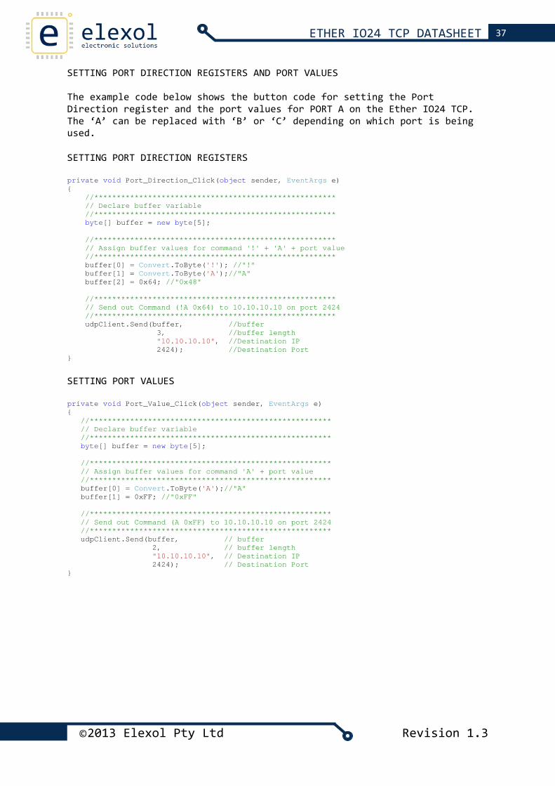
SETTING PORT DIRECTION REGISTERS AND PORT VALUES The example code below shows the button code for setting the Port Direction register and the port values for PORT A on the Ether IO24 TCP. The ‘A’ can be replaced with ‘B’ or ‘C’ depending on which port is being used. SETTING PORT DIRECTION REGISTERS private void Port_Direction_Click(object sender, EventArgs e) { //****************************************************** // Declare buffer variable //****************************************************** byte[] buffer = new byte[5]; //****************************************************** // Assign buffer values for command '!' + 'A' + port value //****************************************************** buffer[0] = Convert.ToByte('!'); //"!" buffer[1] = Convert.ToByte('A');//"A" buffer[2] = 0x64; //"0x48" //****************************************************** // Send out Command (!A 0x64) to 10.10.10.10 on port 2424 //****************************************************** udpClient.Send(buffer, //buffer 3, //buffer length "10.10.10.10", //Destination IP 2424); //Destination Port }
SETTING PORT VALUES private void Port_Value_Click(object sender, EventArgs e) { //****************************************************** // Declare buffer variable //****************************************************** byte[] buffer = new byte[5]; //****************************************************** // Assign buffer values for command 'A' + port value //****************************************************** buffer[0] = Convert.ToByte('A');//"A" buffer[1] = 0xFF; //"0xFF" //****************************************************** // Send out Command (A 0xFF) to 10.10.10.10 on port 2424 //****************************************************** udpClient.Send(buffer, // buffer 2, // buffer length "10.10.10.10", // Destination IP 2424); // Destination Port }
©2013 Elexol Pty Ltd Revision 1.3
38 ETHER IO24 TCP DATASHEET
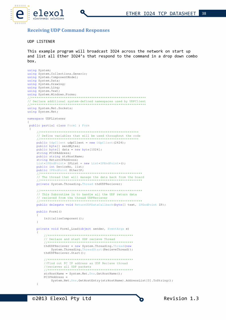
Receiving UDP Command Responses UDP LISTENER This example program will broadcast IO24 across the network on start up and list all Ether IO24’s that respond to the command in a drop down combo box. using System; using System.Collections.Generic; using System.ComponentModel; using System.Data; using System.Drawing; using System.Linq; using System.Text; using System.Windows.Forms; //*************************************************************** // Declare additional system-defined namespaces used by UDPClient //*************************************************************** using System.Net.Sockets; using System.Net; namespace UDPListener { public partial class Form1 : Form { //****************************************************** // Define variables that will be used throughout the code //****************************************************** public UdpClient udpClient = new UdpClient(2424); public byte[] sendBytes; public byte[] data = new byte[1024]; string PCIPAddress; public string strHostName; string ReturnIPAddress; List<IPEndPoint> IPList = new List<IPEndPoint>(); public int DeviceNo, list; public IPEndPoint EtherIP; //******************************************************** // The thread that will manage the data back from the board //******************************************************** private System.Threading.Thread thdUDPReciever; //******************************************************** // This Subroutine is to handle all the UDP return data // recieved from the thread UDPReciever //******************************************************** public delegate void ReturnUDPDataCallback(byte[] text, IPEndPoint IP); public Form1() { InitializeComponent(); } private void Form1_Load(object sender, EventArgs e) { //*********************************************** // Declare and start UDP recieve Thread //*********************************************** thdUDPReciever = new System.Threading.Thread(new System.Threading.ThreadStart(RecieveThread)); thdUDPReciever.Start(); //*********************************************** //Find out PC IP address as UDP Recieve thread //recieves all UDP packets //*********************************************** strHostName = System.Net.Dns.GetHostName(); PCIPAddress = System.Net.Dns.GetHostEntry(strHostName).AddressList[0].ToString(); }
©2013 Elexol Pty Ltd Revision 1.3
39 ETHER IO24 TCP DATASHEET
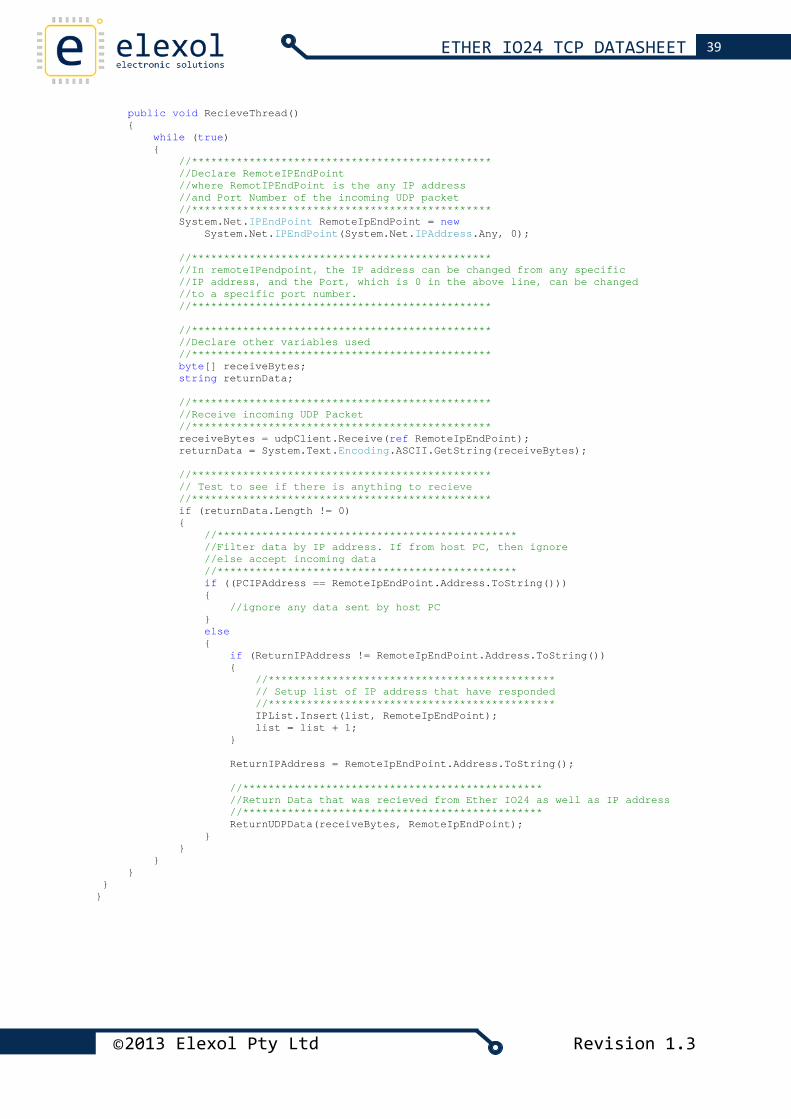
public void RecieveThread() { while (true) { //*********************************************** //Declare RemoteIPEndPoint //where RemotIPEndPoint is the any IP address //and Port Number of the incoming UDP packet //*********************************************** System.Net.IPEndPoint RemoteIpEndPoint = new System.Net.IPEndPoint(System.Net.IPAddress.Any, 0); //*********************************************** //In remoteIPendpoint, the IP address can be changed from any specific //IP address, and the Port, which is 0 in the above line, can be changed //to a specific port number. //*********************************************** //*********************************************** //Declare other variables used //*********************************************** byte[] receiveBytes; string returnData; //*********************************************** //Receive incoming UDP Packet //*********************************************** receiveBytes = udpClient.Receive(ref RemoteIpEndPoint); returnData = System.Text.Encoding.ASCII.GetString(receiveBytes); //*********************************************** // Test to see if there is anything to recieve //*********************************************** if (returnData.Length != 0) { //*********************************************** //Filter data by IP address. If from host PC, then ignore //else accept incoming data //*********************************************** if ((PCIPAddress == RemoteIpEndPoint.Address.ToString())) { //ignore any data sent by host PC } else { if (ReturnIPAddress != RemoteIpEndPoint.Address.ToString()) { //********************************************* // Setup list of IP address that have responded //********************************************* IPList.Insert(list, RemoteIpEndPoint); list = list + 1; } ReturnIPAddress = RemoteIpEndPoint.Address.ToString(); //*********************************************** //Return Data that was recieved from Ether IO24 as well as IP address //*********************************************** ReturnUDPData(receiveBytes, RemoteIpEndPoint); } } } } } }
©2013 Elexol Pty Ltd Revision 1.3
40 ETHER IO24 TCP DATASHEET
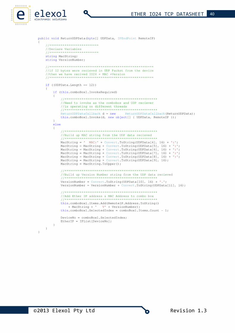
public void ReturnUDPData(byte[] UDPData, IPEndPoint RemoteIP) { //************************** //Declare Variables //************************** string MacString; string VersionNumber; //******************************************************* //if 12 bytes were recieved in UDP Packet from the device //then we have recived IO24 + MAC +Version //******************************************************* if ((UDPData.Length == 12)) { if (this.comboBox1.InvokeRequired) { //************************************************* //Need to invoke as the combobox and UDP reciever //is operating on different threads //************************************************* ReturnUDPDataCallback d = new ReturnUDPDataCallback(ReturnUDPData); this.comboBox1.Invoke(d, new object[] { UDPData, RemoteIP }); } else { //************************************************* //Build up MAC string from the UDP data recieved //************************************************* MacString = " MAC:" + Convert.ToString(UDPData[4], 16) + ":"; MacString = MacString + Convert.ToString(UDPData[5], 16) + ":"; MacString = MacString + Convert.ToString(UDPData[6], 16) + ":"; MacString = MacString + Convert.ToString(UDPData[7], 16) + ":"; MacString = MacString + Convert.ToString(UDPData[8], 16) + ":"; MacString = MacString + Convert.ToString(UDPData[9], 16); MacString = MacString.ToUpper(); //************************************************* //Build up Version Number string from the UDP data recieved //************************************************* VersionNumber = Convert.ToString(UDPData[10], 16) + "."; VersionNumber = VersionNumber + Convert.ToString(UDPData[11], 16); //************************************************* //Add Ether IP address & MAC Address to combo box //************************************************* this.comboBox1.Items.Add(RemoteIP.Address.ToString() + MacString + " V" + VersionNumber); this.comboBox1.SelectedIndex = comboBox1.Items.Count - 1; DeviceNo = comboBox1.SelectedIndex; EtherIP = IPList[DeviceNo]; } } }
©2013 Elexol Pty Ltd Revision 1.3
41 ETHER IO24 TCP DATASHEET
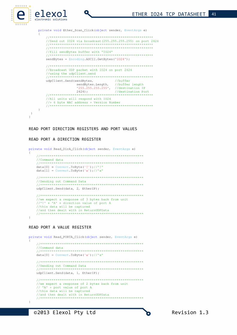
private void Ether_Scan_Click(object sender, EventArgs e) { //****************************************************** //Send out IO24 via broadcast(255.255.255.255) on port 2424 //****************************************************** //****************************************************** //fill sendBytes buffer with "IO24" //****************************************************** sendBytes = Encoding.ASCII.GetBytes("IO24"); //****************************************************** //Broadcast UDP packet with IO24 on port 2424 //using the udpClient.send //****************************************************** udpClient.Send(sendBytes, //buffer sendBytes.Length, //buffer length "255.255.255.255", //destination IP 2424); //destination Port //****************************************************** //All units will respond with IO24 //+ 6 byte MAC address + Version Number //****************************************************** } } } READ PORT DIRECTION REGISTERS AND PORT VALUES READ PORT A DIRECTION REGISTER private void Read_DirA_Click(object sender, EventArgs e) { //****************************************************** //Command data //****************************************************** data[0] = Convert.ToByte('!');//"!" data[1] = Convert.ToByte('a');//"a" //****************************************************** //Sending out Command Data //****************************************************** udpClient.Send(data, 2, EtherIP); //****************************************************** //we expect a response of 3 bytes back from unit //"!" + "A" + direction value of port A //this data will be captured //and then dealt with in ReturnUDPData //****************************************************** }
READ PORT A VALUE REGISTER private void Read_PORTA_Click(object sender, EventArgs e) { //****************************************************** //Command data //****************************************************** data[0] = Convert.ToByte('a');//"a" //****************************************************** //Sending out Command Data //****************************************************** udpClient.Send(data, 1, EtherIP); //****************************************************** //we expect a response of 2 bytes back from unit // "A" + port value of port A //this data will be captured //and then dealt with in ReturnUDPData //****************************************************** }
©2013 Elexol Pty Ltd Revision 1.3
42 ETHER IO24 TCP DATASHEET
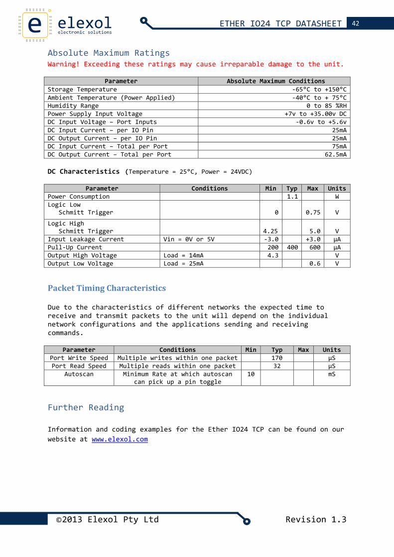
Absolute Maximum Ratings Warning! Exceeding these ratings may cause irreparable damage to the unit.
Parameter Absolute Maximum Conditions Storage Temperature ‐65°C to +150°C Ambient Temperature (Power Applied) ‐40°C to + 75°CHumidity Range 0 to 85 %RHPower Supply Input Voltage +7v to +35.00v DCDC Input Voltage – Port Inputs ‐0.6v to +5.6vDC Input Current – per IO Pin 25mADC Output Current – per IO Pin 25mADC Input Current – Total per Port 75mADC Output Current – Total per Port 62.5mA DC Characteristics (Temperature = 25°C, Power = 24VDC)
Parameter Conditions Min Typ Max UnitsPower Consumption 1.1 WLogic Low Schmitt Trigger 0
0.75 V
Logic High Schmitt Trigger 4.25
5.0 V
Input Leakage Current Vin = 0V or 5V ‐3.0 +3.0 μAPull‐Up Current 200 400 600 μAOutput High Voltage Load = 14mA 4.3 VOutput Low Voltage Load = 25mA 0.6 V
Packet Timing Characteristics Due to the characteristics of different networks the expected time to receive and transmit packets to the unit will depend on the individual network configurations and the applications sending and receiving commands.
Parameter Conditions Min Typ Max UnitsPort Write Speed Multiple writes within one packet 170 μSPort Read Speed Multiple reads within one packet 32 μS
Autoscan Minimum Rate at which autoscan can pick up a pin toggle
10 mS
Further Reading Information and coding examples for the Ether IO24 TCP can be found on our website at www.elexol.com
©2013 Elexol Pty Ltd Revision 1.3
43 ETHER IO24 TCP DATASHEET
©2013 Elexol Pty Ltd Revision 1.3
Technical Support For any questions relating to the Ether IO24 TCP or if we can assist you with integrating the Ether IO24 TCP into your own equipment please contact us by email at [email protected]
Document Revision History
• Ether IO24 TCP Datasheet Revision 1 – Initial document created • Revision 1.1 – Added AutoScan Section, Revised EEPROM Commands • Revision 1.2 – Corrected Absolute maximum Ratings • Revision 1.3 – Product name changed to Ether IO24 TCP.
Product Use Limitations, Warranty and Quality Statement This product is not designed, intended, or recommended for use in systems intended to support or sustain life, or for any other application in which the failure of the product could create a situation where personal injury or death may occur and should not be used for those applications.
The Ether IO24 TCP is warranted to be free from manufacture defects for a period of 12 months from the date of purchase. Subjecting the device to conditions beyond the Absolute Maximum Ratings listed in this document will invalidate this warranty. As the Ether IO24 TCP is a static sensitive device, anti static procedures should be used in its handling.
All Ether IO24 TCP units are tested during manufacture and are despatched free of defects.
Elexol is committed to providing products of the highest quality. Should you experience any product quality issues with this product please contact our quality assurance manager at the above address.
Disclaimer This product and its documentation are provided as‐is and no warranty is made or implied as to their suitability for any particular purpose. Elexol Pty Ltd will not accept any claim for damages arising from the use of this product or its documentation. This document provides information on our product and all efforts are made to ensure the accuracy of the information contained within. The specifications of the product are subject to change and continual improvement without notification.
Other than the extent permitted by law and subject to the Trade Practice Act, all and any liability for consequential loss or damage arising from
©2013 Elexol Pty Ltd Revision 1.3
44 ETHER IO24 TCP DATASHEET
an Elexol Ether IO24 TCP module is hereby limited, at discretion of Elexol Pty Ltd, to replacement or repair.