etag 001-5 - metalldübel zur verankerung im beton · metalldÜbel zur verankerung im beton teil 5:...
TRANSCRIPT
Leitlinie für die europäische technische Zulassung (ETAG)
ETAG 001
METALLDÜBEL ZUR VERANKERUNG IM BETON
TEIL 5: VERBUNDDÜBEL
Ausgabe 2002 Änderungen 2006, 2008 und 2013
OIB-467-010/13
Vorbemerkungen zur Leitlinie für die europäische technische Zulassung für
METALLDÜBEL ZUR VERANKERUNG IM BETON
TEIL 5: VERBUNDDÜBEL
Vorbemerkungen
Leitlinien für die europäische technische Zulassung wurden aufgrund eines von der Kommission der Europäischen Gemeinschaften nach Art. 11 Abs. 1 der Richtlinie des Rates vom 21. Dezember 1988 zur Angleichung der Rechts- und Verwaltungsvorschriften der Mitgliedstaaten über Bauprodukte (89/106/EWG) (Bauproduktenrichtlinie) erteilten Auftrages vom Gremium der von den Mitgliedstaaten bestimmten Zulassungsstellen (EOTA) erarbeitet.
Leitlinien für die europäische technische Zulassung können von Technischen Bewertungsstellen gemäß Art. 66 Abs. 3 der Verordnung (EU) Nr. 305/2011 (Bauproduktenverordnung) als Europäisches Bewertungsdokument verwendet werden. Leitlinien sind damit die Grundlage für Europäische Technische Bewertungen.
In Zweifelsfällen bzw. in Fällen von Übersetzungsfehlern ist die im EOTA-Sekretariat (Kunstlaan 40, Avenue des Arts, 1040 Bruxelles, Belgien) vorliegende Originalfassung der Leitlinie maßgebend.
Stand, August 2013
European Organisation for Technical Approvals Europäische Organisation für Technische Zulassungen Organisation Européenne pour l‘Agrément Technique
ETAG 001
GUIDELINE FOR EUROPEAN TECHNICAL APPROVAL OF
METAL ANCHORS FOR USE IN CONCRETE
Part five: BONDED ANCHORS Edition March 2002
1st Amended November 2006 2nd Amended February 2008
3rd Amended April 2013
Copyright © 2012 EOTA
EOTA Avenue des Arts 40 Kunstlaan
B – 1040 Brussels

INTRODUCTORY NOTES
In this Part requirements, criteria and test information applicable only for bonded anchors are given. They may be additional to Part 1 or may replace the provisions in Part 1. The same numbering of paragraphs as in Part 1 is used. If a paragraph is not mentioned, then the text in Part 1 applies without modification.
TABLE OF CONTENTS
PART FIVE:
BONDED ANCHORS
2 SCOPE............................................................................................................................................................3 2.0 General ...........................................................................................................................................................3 2.1 Anchors ...........................................................................................................................................................3
2.1.1 Types and operating principles ..........................................................................................................3 2.1.2 Materials.............................................................................................................................................5
2.2 Concrete..........................................................................................................................................................5 2.2.2 Concrete members ............................................................................................................................5
2.3 Actions ............................................................................................................................................................6 2.4 Categories.......................................................................................................................................................6 3 TERMINOLOGY .............................................................................................................................................6 3.2 Particular terminology and abbreviations ........................................................................................................6
3.2.1 General (additional terms) .................................................................................................................6 4 REQUIREMENTS FOR WORKS....................................................................................................................7 4.1 Mechanical resistance and stability (ER 1) .....................................................................................................7 4.3 Hygiene, health and the environment..............................................................................................................7
4.3.1 Content and /or release of dangerous substances ............................................................................7 5 METHODS OF VERIFICATION......................................................................................................................8 5.0 General ...........................................................................................................................................................8 5.1 Methods related to 4.1 (mechanical resistance and stability) .........................................................................9
5.1.1 General ..............................................................................................................................................9 5.1.2 Tests for suitability ...........................................................................................................................11 5.1.3 Tests for admissible service conditions ...........................................................................................17 5.1.4 Tests for checking durability ........................................................................................................20
5.3 Methods related to 4.3 (hygiene, health and the environment).....................................................................21 5.3.1 Method of verification...................................................................................................................21
6 ASSESSING AND JUDGING THE FITNESS OF ANCHORS FOR AN INTENDED USE ...........................21 6.0(b) Conversion of ultimate loads to take account of concrete and steel strength......................................21 6.1 Assessing and judging related to 4.1 (mechanical resistance and stability) .................................................21
6.1.1 Suitability ..........................................................................................................................................21 6.1.2 Admissible service conditions ..........................................................................................................24 6.1.3 Assessment of durability ..................................................................................................................29
6.3 Assessment related to ER3 ..........................................................................................................................29 6.3.1 Methods of assessing and judging...................................................................................................29
6.7 Identification of anchors ................................................................................................................................30 7 ASSUMPTIONS UNDER WHICH THE ETA IS TO BE ASSESSED ...........................................................31 7.1 Design methods for anchorages ...................................................................................................................31 7.2 Recommendations for packaging, transport and storage.............................................................................31 7.3 Installation of anchors ...................................................................................................................................31 9 THE ETA CONTENT ....................................................................................................................................32
ETAG 001-5 - 2 -
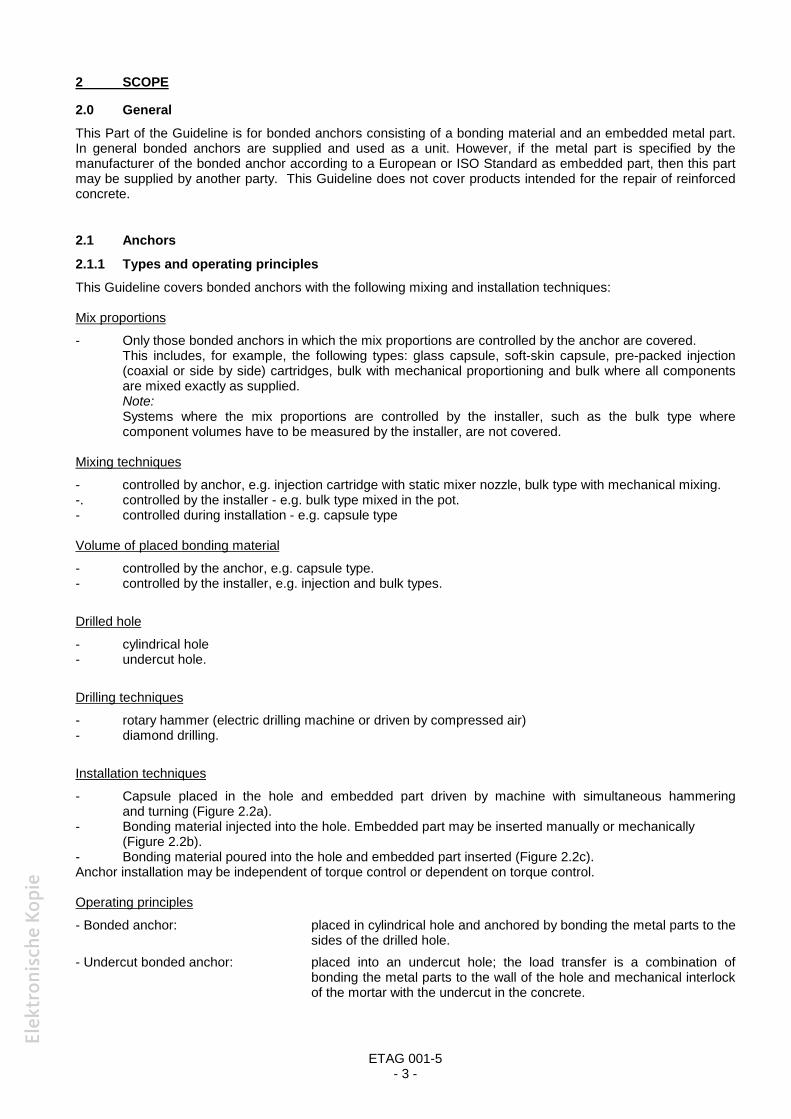
2 SCOPE
2.0 General This Part of the Guideline is for bonded anchors consisting of a bonding material and an embedded metal part. In general bonded anchors are supplied and used as a unit. However, if the metal part is specified by the manufacturer of the bonded anchor according to a European or ISO Standard as embedded part, then this part may be supplied by another party. This Guideline does not cover products intended for the repair of reinforced concrete.
2.1 Anchors
2.1.1 Types and operating principles This Guideline covers bonded anchors with the following mixing and installation techniques:
Mix proportions
- Only those bonded anchors in which the mix proportions are controlled by the anchor are covered. This includes, for example, the following types: glass capsule, soft-skin capsule, pre-packed injection (coaxial or side by side) cartridges, bulk with mechanical proportioning and bulk where all components are mixed exactly as supplied. Note: Systems where the mix proportions are controlled by the installer, such as the bulk type where component volumes have to be measured by the installer, are not covered.
Mixing techniques
- controlled by anchor, e.g. injection cartridge with static mixer nozzle, bulk type with mechanical mixing. -. controlled by the installer - e.g. bulk type mixed in the pot. - controlled during installation - e.g. capsule type
Volume of placed bonding material
- controlled by the anchor, e.g. capsule type. - controlled by the installer, e.g. injection and bulk types.
Drilled hole
- cylindrical hole - undercut hole.
Drilling techniques
- rotary hammer (electric drilling machine or driven by compressed air) - diamond drilling.
Installation techniques
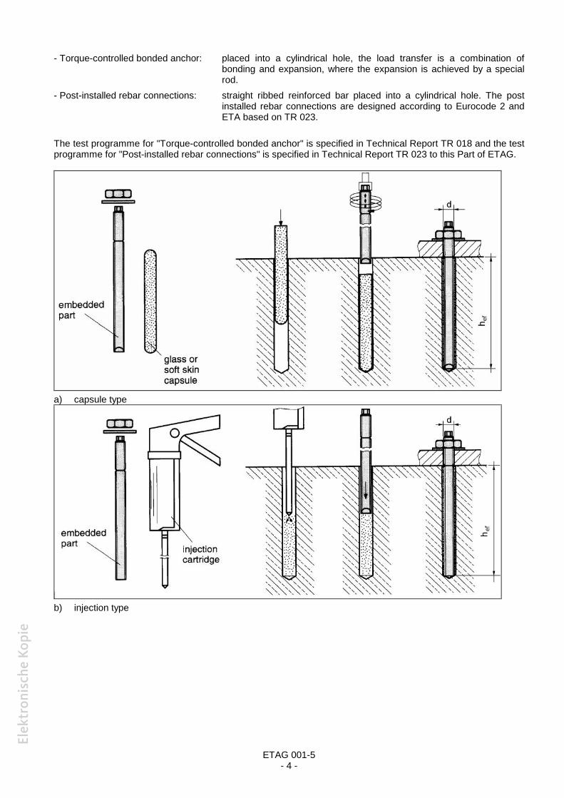
- Capsule placed in the hole and embedded part driven by machine with simultaneous hammering and turning (Figure 2.2a).
- Bonding material injected into the hole. Embedded part may be inserted manually or mechanically (Figure 2.2b).
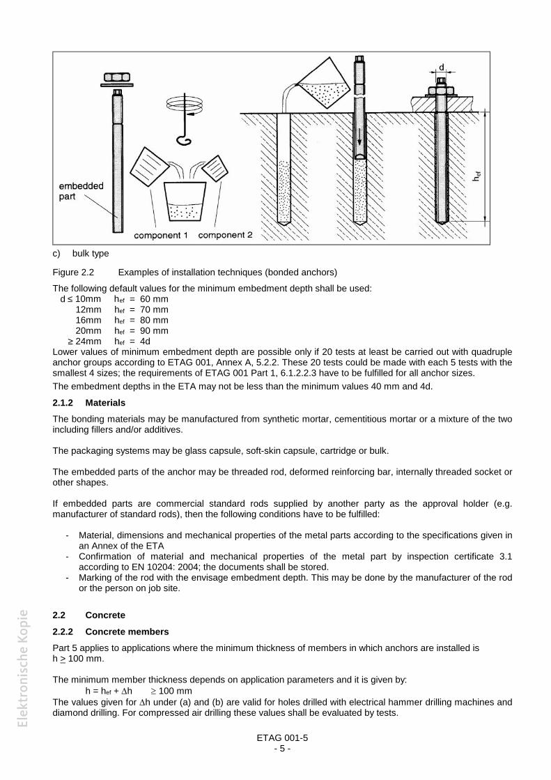
- Bonding material poured into the hole and embedded part inserted (Figure 2.2c). Anchor installation may be independent of torque control or dependent on torque control.
Operating principles
- Bonded anchor: placed in cylindrical hole and anchored by bonding the metal parts to the sides of the drilled hole.
- Undercut bonded anchor: placed into an undercut hole; the load transfer is a combination of bonding the metal parts to the wall of the hole and mechanical interlock of the mortar with the undercut in the concrete.
ETAG 001-5 - 3 -
ETAG 001-5- 4 -
- Torque-controlled bonded anchor: placed into a cylindrical hole, the load transfer is a combination ofbonding and expansion, where the expansion is achieved by a specialrod.
- Post-installed rebar connections: straight ribbed reinforced bar placed into a cylindrical hole. The postinstalled rebar connections are designed according to Eurocode 2 andETA based on TR 023.
The test programme for "Torque-controlled bonded anchor" is specified in Technical Report TR 018 and the testprogramme for "Post-installed rebar connections" is specified in Technical Report TR 023 to this Part of ETAG.
a) capsule type
b) injection type
ETAG 001-5- 5 -
c) bulk type
Figure 2.2 Examples of installation techniques (bonded anchors)
The following default values for the minimum embedment depth shall be used:d ≤ 10mm hef = 60 mm
12mm hef = 70 mm16mm hef = 80 mm20mm hef = 90 mm
≥ 24mm hef = 4dLower values of minimum embedment depth are possible only if 20 tests at least be carried out with quadrupleanchor groups according to ETAG 001, Annex A, 5.2.2. These 20 tests could be made with each 5 tests with thesmallest 4 sizes; the requirements of ETAG 001 Part 1, 6.1.2.2.3 have to be fulfilled for all anchor sizes.The embedment depths in the ETA may not be less than the minimum values 40 mm and 4d.
2.1.2 MaterialsThe bonding materials may be manufactured from synthetic mortar, cementitious mortar or a mixture of the twoincluding fillers and/or additives.
The packaging systems may be glass capsule, soft-skin capsule, cartridge or bulk.
The embedded parts of the anchor may be threaded rod, deformed reinforcing bar, internally threaded socket orother shapes.
If embedded parts are commercial standard rods supplied by another party as the approval holder (e.g.manufacturer of standard rods), then the following conditions have to be fulfilled:
- Material, dimensions and mechanical properties of the metal parts according to the specifications given inan Annex of the ETA
- Confirmation of material and mechanical properties of the metal part by inspection certificate 3.1according to EN 10204: 2004; the documents shall be stored.
- Marking of the rod with the envisage embedment depth. This may be done by the manufacturer of the rodor the person on job site.
2.2 Concrete
2.2.2 Concrete membersPart 5 applies to applications where the minimum thickness of members in which anchors are installed ish > 100 mm.
The minimum member thickness depends on application parameters and it is given by:h = hef + h 100 mm
The values given for h under (a) and (b) are valid for holes drilled with electrical hammer drilling machines anddiamond drilling. For compressed air drilling these values shall be evaluated by tests.

ETAG 001-5- 6 -
(a) h 2do
30 mmApplicable to all anchor types. No application restrictions.
(b) h do
15 mmApplicable to all anchor types.This may be applied where the remote face of the concrete member is accessible and can beinspected to ensure there has been no break-through. In case of a break-through, measures shall betaken to ensure that the full bonded length, hef, will be achieved and any potential loss of bondingmaterial, for instance due to spalling, shall be compensated for. When this is not possible, e.g. withcapsule anchors, then the hole shall be redrilled at a distance according to Part 1, 7.3.
(c) h = 0Applicable to injection type anchors.This may be applied where it can be ensured that the full bonded length, hef, will be achieved, andcompensation shall be made for any potential loss of bonding material.
Option a) is mandatory.The manufacturer may additionally apply for an ETA to options (b) or (c). In those tests where minimum memberthickness is required, they shall be carried out with each anchor size in its minimum member thickness.
2.3 ActionsIn contrast to Part 1, the transmission of compressive forces on the anchor is allowed.
2.4 CategoriesIn contrast to Part 1, it is necessary to consider the different intended uses according to installation or serviceconditions in the base material.
use category 1: Installation in dry or wet concreteService condition in dry or wet concrete
use category 2: Installation in dry or wet concrete or in a flooded hole (not sea water)Service condition in dry or wet concrete or under water (not sea water)
3 TERMINOLOGY
3.2 Particular terminology and abbreviations
3.2.1 General (additional terms)Service temperature range: Range of ambient temperatures after installation and during the lifetime of theanchorage.
Short term temperature: Temperatures within the service temperature range which vary over short intervals, e.g.day/night cycles and freeze/thaw cycles.
Maximum short term temperature: Upper limit of the service temperature range.
Long term temperature: Temperature, within the service temperature range, which will be approximatelyconstant over significant periods of time. Long term temperatures will include constant or near constanttemperatures, such as those experienced in cold stores or next to heating installations.
Maximum long term temperature: Specified by the manufacturer within the range of 0,0,6 times to 1,0 x timesthe maximum short term temperature.
Normal ambient temperature: Temperature 21 °C 3 °C (for test conditions only)
ETAG 001-5- 7 -
Open time: The maximum time from end of mixing to when the insertion of the anchor into the bonding materialshall be completed.
Installation ambient temperature range: The environmental temperature range of the base material allowed bythe manufacturer for installation.
Anchor component installation temperature range: The temperature range of the bonding material andembedded part immediately prior to installation.
Curing time: The minimum time from the end of mixing to the time when the anchor may be torqued or loaded(whichever is longer). The curing time depends on the ambient temperature.
4 REQUIREMENTS FOR WORKS
4.1 Mechanical resistance and stability (ER 1)
4.1.1.2 Temperature
Service temperature range
The functioning of a bonded anchor, including its ability to sustain its design load with an appropriate safetyfactor and to limit displacements, shall not be adversely affected by temperatures in the concrete near to thesurface within a temperature range to be specified by the manufacturer which may be either:
(a) - 40 °C to + 40 °C (max short term temperature + 40 °C and max long term temperature + 24 °C)(b) - 40 °C to + 80 °C (max short term temperature + 80 °C and max long term temperature + 50 °C)(c) on manufacturers request with –40 °C to T1 (short term:T1>+40 °C, long term:0,0,6 T1 to 1,0 T1)
In general bonded anchors are not affected by service temperatures down to - 40 °C. If there is no experiencefor unknown bonding materials on their performance at - 40 °C then normal pull-out tests at - 40 °C will berequired.
The performance shall not be adversely affected by short term temperatures within the service temperaturerange or by long term temperatures up to the maximum long term temperature.Performance at the maximum long term temperature and maximum short term temperature is checked by testsdescribed in 5.1.3.1(a) and 5.1.2.5.
Installation temperature range and curing time
Functioning shall also be validated for the range of installation temperatures to be specified by the manufacturerin terms of lowest and highest installation ambient temperatures, normally in the range 0 °C to + 40 °C, lowestand highest anchor component installation temperatures and associated curing times.
Performance at lowest installation temperature and at normal ambient temperature is checked by tests asdescribed in 5.1.3.1(b) and 5.1.3.1(c). The manufacturer has to provide corresponding data for the upperinstallation temperature limit and the associated curing times and for temperatures in between.
4.1.2.1 Correct installation
In addition to the requirements of Part 1, 4.1.2.1:Dependent on the applications as specified by the manufacturer, it shall be possible to install anchors in dry andwet concrete (use category 1 according to 2.4) or in dry and wet concrete and in a flooded hole (not seawater)(use category 2 according to 2.4) and also in the specified installation directions with the drillingtechniques specified by the manufacturer.
4.3 Hygiene, health and the environment
4.3.1 Content and /or release of dangerous substancesThe applicant shall either
- submit the chemical constitution and composition of the product and/or constituents of the product to theApproval Body which will observe strict rules of confidentiality
or
ETAG 001-5- 8 -
- submit a written declaration to the Approval Body stating whether or not and in which concentration theproduct and/or constituents of the product contains substances which have to be classified as dangerousaccording to Directive 67/548/EEC and Regulation (EC) No 1272/2008 and listed in the "Indicative list ondangerous substances" of the EGDS - taking into account the installation conditions of the constructionproduct and the release scenarios resulting from there.
The use of recycled materials shall always be indicated, because this could lead to the implementation of furtherassessment and verification methods.The information concerning the presence of dangerous substances listed in Council Directive 67/548/EEC andRegulation (EC) No 1272/2008 regulated at European level and listed in the "Indicative list on dangeroussubstances" of the EGDS (Expert Group on Dangerous Substances of the EU Commission) and/or of otherdangerous substances, shall be circulated as part of the evaluation report by the issuing Approval Body to theother Approval Bodies, under strict conditions of confidentiality.
5 METHODS OF VERIFICATION
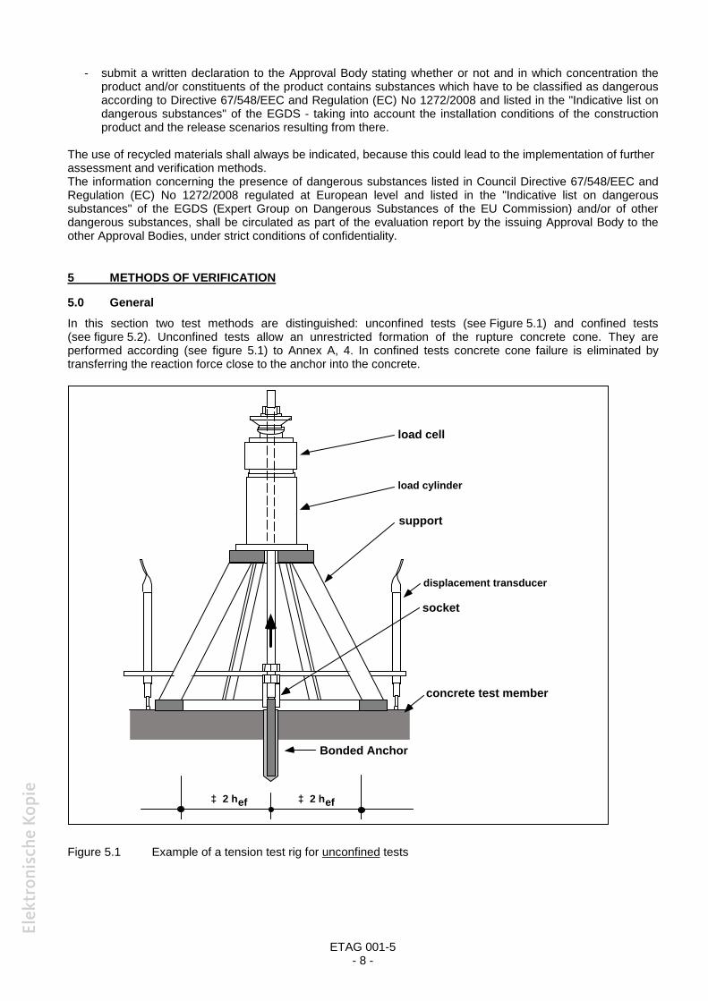
5.0 GeneralIn this section two test methods are distinguished: unconfined tests (see Figure 5.1) and confined tests(see figure 5.2). Unconfined tests allow an unrestricted formation of the rupture concrete cone. They areperformed according (see figure 5.1) to Annex A, 4. In confined tests concrete cone failure is eliminated bytransferring the reaction force close to the anchor into the concrete.
Figure 5.1 Example of a tension test rig for unconfined tests
load cell
support
socket
Bonded Anchor
concrete test member
2 hef
displacement transducer
2 hef
load cylinder
ETAG 001-5- 9 -
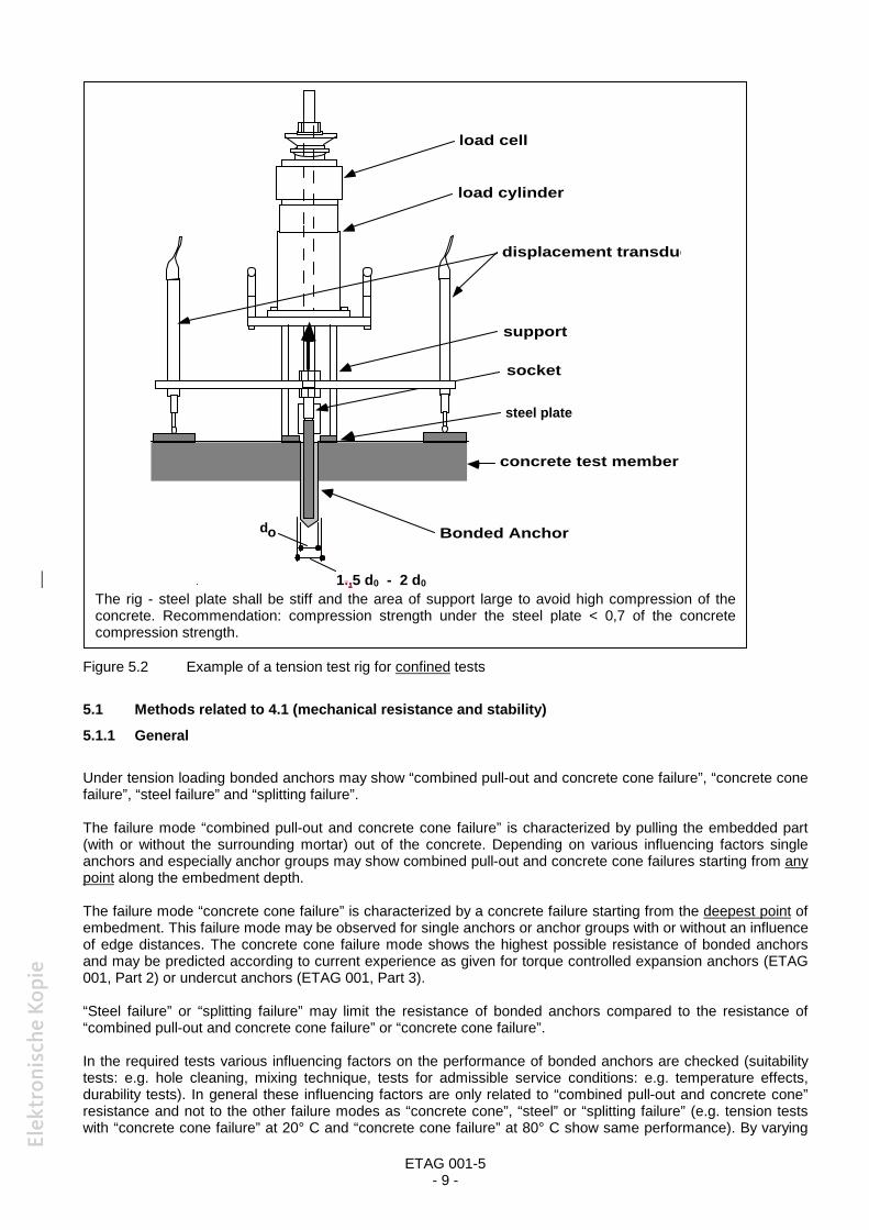
Figure 5.2 Example of a tension test rig for confined tests
5.1 Methods related to 4.1 (mechanical resistance and stability)
5.1.1 General
Under tension loading bonded anchors may show “combined pull-out and concrete cone failure”, “concrete conefailure”, “steel failure” and “splitting failure”.
The failure mode “combined pull-out and concrete cone failure” is characterized by pulling the embedded part(with or without the surrounding mortar) out of the concrete. Depending on various influencing factors singleanchors and especially anchor groups may show combined pull-out and concrete cone failures starting from anypoint along the embedment depth.
The failure mode “concrete cone failure” is characterized by a concrete failure starting from the deepest point ofembedment. This failure mode may be observed for single anchors or anchor groups with or without an influenceof edge distances. The concrete cone failure mode shows the highest possible resistance of bonded anchorsand may be predicted according to current experience as given for torque controlled expansion anchors (ETAG001, Part 2) or undercut anchors (ETAG 001, Part 3).
“Steel failure” or “splitting failure” may limit the resistance of bonded anchors compared to the resistance of“combined pull-out and concrete cone failure” or “concrete cone failure”.
In the required tests various influencing factors on the performance of bonded anchors are checked (suitabilitytests: e.g. hole cleaning, mixing technique, tests for admissible service conditions: e.g. temperature effects,durability tests). In general these influencing factors are only related to “combined pull-out and concrete cone”resistance and not to the other failure modes as “concrete cone”, “steel” or “splitting failure” (e.g. tension testswith “concrete cone failure” at 20° C and “concrete cone failure” at 80° C show same performance). By varying
load cylinder
load cell
displacement transducer
support
socket
Bonded Anchor
concrete test member
steel plate
do mm
do
The rig - steel plate shall be stiff and the area of support large to avoid high compression of theconcrete. Recommendation: compression strength under the steel plate < 0,7 of the concretecompression strength.
load cylinder
load cell
displacement transducer
support
socket
Bonded Anchor
concrete test member
steel plate
do mm
do
1.,5 d0 - 2 d0
ETAG 001-5- 10 -
the influencing factors the failure mode may change (e.g. tests with “concrete cone failure” at 20° C and“combined pull-out and concrete cone failure” at 80° C show lower performance at 80° C). If the tests areperformed in such a way that “combined pull-out and concrete cone failure” is observed (e.g. at 20° C and 80° C)the largest difference in performance is observed. This influencing factor is decisive for the evaluation of abonded anchor system.
So the main aim of the test regime is to establish a resistance for “combined pull-out and concrete cone failure” -if required, modified by the influencing factors-, which is published as Rk in the ETA. The characteristic bondresistance allows a design of bonded anchors for “combined pull-out and concrete cone” resistance at variableembedment depth with or without group- or edge effects. The resistance for “concrete cone” and “steel failure”can be calculated according to current experience.
To avoid “steel failure” in the tests embedded parts of a higher strength than specified by the manufacturer andpublished in the ETA may be used as long as the functioning of the anchor is not influenced. This condition isfulfilled if the geometry of the embedded part of higher strength steel is identical with the specified embeddedpart.In cases where the use of high strength anchor elements (steel strength ≥ 10.9) is insufficient to prevent “steelfailure” the anchor embedment depth shall be reduced. This principle may overrule the required embedmentdepth for the suitability tests (5.1.2) and admissible service condition tests (5.1.3).Special conditions for tests according to line 1 of Table 5.1 or 5.2 are given in 5.1.2.
The unconfined tests with minimum specified embedment depth in the admissible service condition tests mayshow “concrete cone failure”. If these results are used for evaluating the characteristic bond resistance(eventually modified by the various influencing factors) the approach is conservative. More precise results maybe achieved if the minimum embedment depth is chosen in a way that bond failure (“combined pull-out andconcrete cone failure”) is decisive.
Bonded anchors with a high bond resistance may show only “concrete cone failure” or “steel failure” inunconfined tests. In this case it is recommended to perform all tests as confined tests and to evaluate Rk takingthe modification factor αsetup into account (see Equation 6.17.1).
For the assessment of a bonded anchor the overall test programme has to be carried out including at least thefollowing minimum number of different concrete batches within the programme of testing:
Assessment for C20/25: on at least 3 different batches, if the concrete comes from differentconcrete supplierson at least 4 different batches, if the concrete comes from the sameconcrete supplier
Assessment for C50/60: on at least 2 different batches, if the concrete comes from the same or fromdifferent concrete suppliers.
If concrete batches come from the same concrete supplier it shall be ensured that each batch is made from adifferent delivery of either cement or aggregates.
Reference Tension Tests (R) shall be performed because they are needed for the evaluation of the results of thesuitability tests and to take account of the influence of certain parameters on the tension load resistance ofbonded anchors. They shall be made in each batch. All reference tests shall be carried out as follows:
in dry concrete at normal ambient temperature (T = + 21° C + 3 °C) anchor installation in accordance with the manufacturer’s published instructions as confined test; they shall be made at approximately the same curing time as the corresponding
suitability tests or tests for admissible service condition.In general, the reference tests shall be made in the same concrete batch as the tests to which they shall becompared (for exception, see note (6) in Table 5.1 and note (4) in Table 5.2). The reference tests shall be madein non-cracked concrete (cracked concrete, w = 0,3mm), if their results shall be compared with results of testsin non-cracked concrete (cracked concrete).
It is necessary to carry out at least 5 reference tests in each series. If the coefficient of variation of the failureloads is > 15 %, then the number of reference tests shall be increased.

ETAG 001-5- 11 -
If the manufacturer applies for embedded parts of bonded anchors which are geometrically identical but ofdifferent material, then all tests shall be made with one material. For the other material, only the torque testsaccording to Part 1, Table 5.1 or 5.2, line 7 shall be carried out and if the embedded part has a reduced sectionalong the length shear tests according to Part 1, Table 5.4, line 5 and 6 or line 7 and 8 for the evaluation of thecharacteristic shear resistance are necessary.
If the approval is to cover more than one drilling technique, then all tests shall be done with all drillingtechniques.
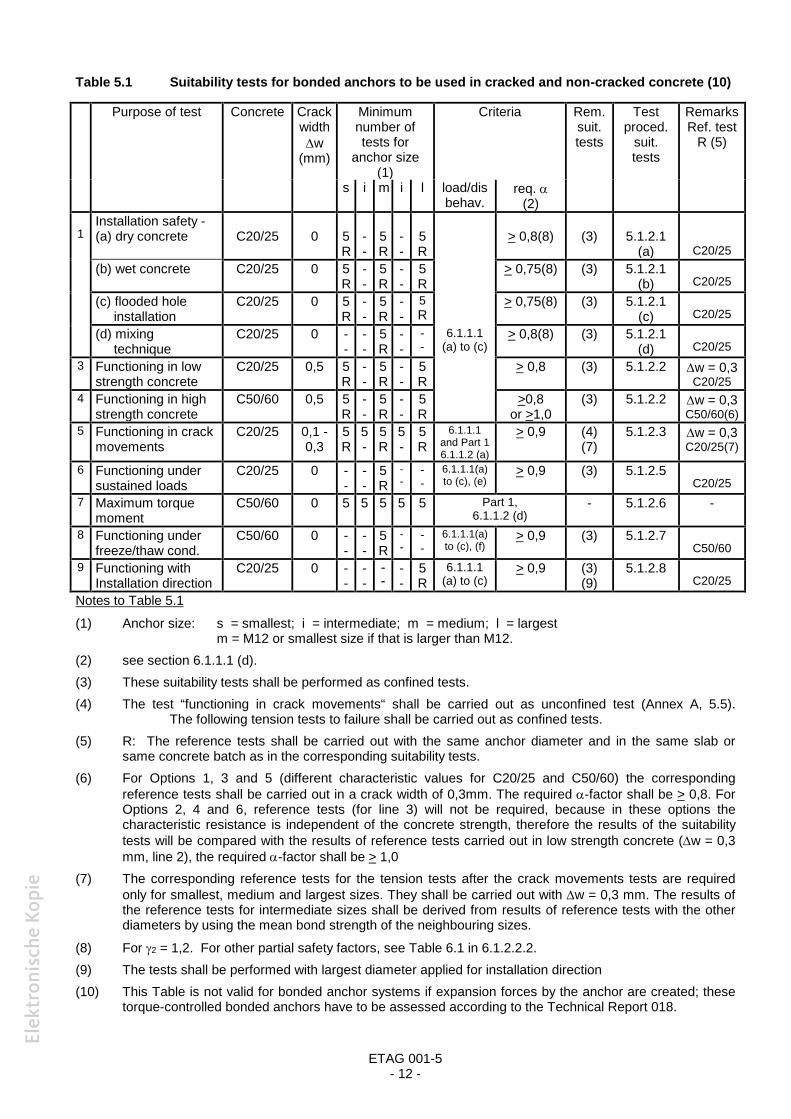
5.1.2 Tests for suitabilityThe types of tests, test conditions, the number of required tests and the criteria applied to the results are given inTable 5.1 (anchors for use in cracked and non-cracked concrete) and Table 5.2 (anchors for use in non-crackedconcrete only). Detailed information about special tests are given in the chapters after the Tables.
In all suitability tests, the hole shall be drilled with a drill bit dcut,m. In general a torque shall not be applied to theanchor. Only in torque tests are the anchors torqued to failure.
The suitability tests shall be performed with the depth requested by the manufacturer. If the manufacturerapplies for bonded anchors with several embedment depths, the installation safety tests according to line 1,Table 5.1 or 5.2 shall be done with the maximum embedment depth requested by the manufacturer, the othersuitability tests with the medium value between the minimum and maximum requested embedment depth.To avoid steel failure in the installation safety tests with maximum embedment depth, as an example thefollowing test procedure may be employed:Use a test member consisting of two concrete blocks which are stacked on the top of each other withoutpermanent connection. The drilling and cleaning of the hole as well as the injection of the hole for anchors withthe maximum embedment depth is done in the two parts. After that remove the upper concrete block, set theanchor in the bottom block and after curing carry out the tension test.
ETAG 001-5- 12 -
Table 5.1 Suitability tests for bonded anchors to be used in cracked and non-cracked concrete (10)
Purpose of test Concrete Crackwidthw
(mm)
Minimumnumber oftests for
anchor size(1)
Criteria Rem.suit.tests
Testproced.
suit.tests
RemarksRef. test
R (5)
s i m i l load/disbehav.
req. (2)
1Installation safety -(a) dry concrete C20/25 0 5
R--
5R
--
5R
> 0,8(8) (3) 5.1.2.1(a) C20/25
(b) wet concrete C20/25 0 5R
--
5R
--
5R
> 0,75(8) (3) 5.1.2.1(b) C20/25
(c) flooded holeinstallation
C20/25 0 5R
--
5R
--
5R
> 0,75(8) (3) 5.1.2.1(c) C20/25
(d) mixingtechnique
C20/25 0 --
--
5R
--
--
6.1.1.1(a) to (c)
> 0,8(8) (3) 5.1.2.1(d) C20/25
3 Functioning in lowstrength concrete
C20/25 0,5 5R
--
5R
--
5R
> 0,8 (3) 5.1.2.2 w = 0,3C20/25
4 Functioning in highstrength concrete
C50/60 0,5 5R
--
5R
--
5R
>0,8or >1,0
(3) 5.1.2.2 w = 0,3C50/60(6)
5 Functioning in crackmovements
C20/25 0,1 -0,3
5R
5-
5R
5-
5R
6.1.1.1and Part 16.1.1.2 (a)
> 0,9 (4)(7)
5.1.2.3 w = 0,3C20/25(7)
6 Functioning undersustained loads
C20/25 0 --
--
5R
--
--
6.1.1.1(a)to (c), (e)
> 0,9 (3) 5.1.2.5C20/25
7 Maximum torquemoment
C50/60 0 5 5 5 5 5 Part 1,6.1.1.2 (d)
- 5.1.2.6 -
8 Functioning underfreeze/thaw cond.
C50/60 0 --
--
5R
--
--
6.1.1.1(a)to (c), (f)
> 0,9 (3) 5.1.2.7C50/60
9 Functioning withInstallation direction
C20/25 0 --
--
--
--
5R
6.1.1.1(a) to (c)
> 0,9 (3)(9)
5.1.2.8C20/25
Notes to Table 5.1
(1) Anchor size: s = smallest; i = intermediate; m = medium; l = largestm = M12 or smallest size if that is larger than M12.
(2) see section 6.1.1.1 (d).(3) These suitability tests shall be performed as confined tests.(4) The test “functioning in crack movements“ shall be carried out as unconfined test (Annex A, 5.5).
The following tension tests to failure shall be carried out as confined tests.(5) R: The reference tests shall be carried out with the same anchor diameter and in the same slab or
same concrete batch as in the corresponding suitability tests.(6) For Options 1, 3 and 5 (different characteristic values for C20/25 and C50/60) the corresponding
reference tests shall be carried out in a crack width of 0,3mm. The required -factor shall be > 0,8. ForOptions 2, 4 and 6, reference tests (for line 3) will not be required, because in these options thecharacteristic resistance is independent of the concrete strength, therefore the results of the suitabilitytests will be compared with the results of reference tests carried out in low strength concrete (w = 0,3mm, line 2), the required -factor shall be > 1,0
(7) The corresponding reference tests for the tension tests after the crack movements tests are requiredonly for smallest, medium and largest sizes. They shall be carried out with w = 0,3 mm. The results ofthe reference tests for intermediate sizes shall be derived from results of reference tests with the otherdiameters by using the mean bond strength of the neighbouring sizes.
(8) For 2 = 1,2. For other partial safety factors, see Table 6.1 in 6.1.2.2.2.(9) The tests shall be performed with largest diameter applied for installation direction(10) This Table is not valid for bonded anchor systems if expansion forces by the anchor are created; these
torque-controlled bonded anchors have to be assessed according to the Technical Report 018.
ETAG 001-5- 13 -
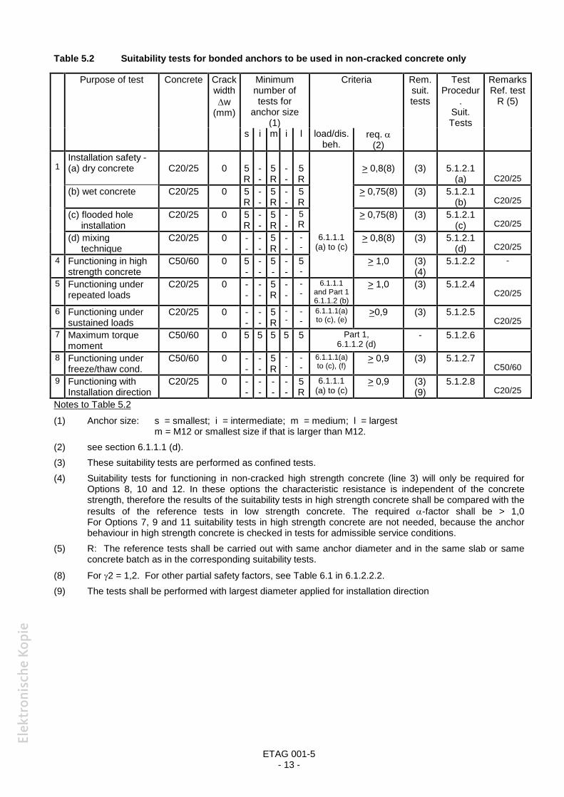
Table 5.2 Suitability tests for bonded anchors to be used in non-cracked concrete only
Purpose of test Concrete Crackwidthw
(mm)
Minimumnumber oftests for
anchor size(1)
Criteria Rem.suit.tests
TestProcedur
.Suit.Tests
RemarksRef. test
R (5)
s i m i l load/dis.beh.
req. (2)
1Installation safety -(a) dry concrete C20/25 0 5
R--
5R
--
5R
> 0,8(8) (3) 5.1.2.1(a) C20/25
(b) wet concrete C20/25 0 5R
--
5R
--
5R
> 0,75(8) (3) 5.1.2.1(b) C20/25
(c) flooded holeinstallation
C20/25 0 5R
--
5R
--
5R
> 0,75(8) (3) 5.1.2.1(c) C20/25
(d) mixingtechnique
C20/25 0 --
--
5R
--
--
6.1.1.1(a) to (c)
> 0,8(8) (3) 5.1.2.1(d) C20/25
4 Functioning in highstrength concrete
C50/60 0 5-
--
5-
--
5-
> 1,0 (3)(4)
5.1.2.2 -
5 Functioning underrepeated loads
C20/25 0 --
--
5R
--
--
6.1.1.1and Part 16.1.1.2 (b)
> 1,0 (3) 5.1.2.4C20/25
6 Functioning undersustained loads
C20/25 0 --
--
5R
--
--
6.1.1.1(a)to (c), (e)
>0,9 (3) 5.1.2.5C20/25
7 Maximum torquemoment
C50/60 0 5 5 5 5 5 Part 1,6.1.1.2 (d)
- 5.1.2.6
8 Functioning underfreeze/thaw cond.
C50/60 0 --
--
5R
--
--
6.1.1.1(a)to (c), (f)
> 0,9 (3) 5.1.2.7C50/60
9 Functioning withInstallation direction
C20/25 0 --
--
--
--
5R
6.1.1.1(a) to (c)
> 0,9 (3)(9)
5.1.2.8C20/25
Notes to Table 5.2
(1) Anchor size: s = smallest; i = intermediate; m = medium; l = largestm = M12 or smallest size if that is larger than M12.
(2) see section 6.1.1.1 (d).(3) These suitability tests are performed as confined tests.(4) Suitability tests for functioning in non-cracked high strength concrete (line 3) will only be required for
Options 8, 10 and 12. In these options the characteristic resistance is independent of the concretestrength, therefore the results of the suitability tests in high strength concrete shall be compared with theresults of the reference tests in low strength concrete. The required -factor shall be > 1,0For Options 7, 9 and 11 suitability tests in high strength concrete are not needed, because the anchorbehaviour in high strength concrete is checked in tests for admissible service conditions.
(5) R: The reference tests shall be carried out with same anchor diameter and in the same slab or sameconcrete batch as in the corresponding suitability tests.
(8) For 2 = 1,2. For other partial safety factors, see Table 6.1 in 6.1.2.2.2.(9) The tests shall be performed with largest diameter applied for installation direction
ETAG 001-5- 14 -
5.1.2.1 Installation safety tests
Confined tension tests in non-cracked concrete C20/25.
The following test conditions are defined for drilling the hole with an electric hammer drilling machine. In generalthe conditions are also valid for other drilling techniques. However some modifications of the installation safetytests might be necessary which shall be agreed by the Approval Bodies.
5.1.2.1 (a) Effect of hole cleaning technique in dry substrate
Tests in dry concrete.
Drill downwards to the depth defined by the manufacturer.Clean the hole with the hand pump and brush supplied by the manufacturer, using two blowing and one brushingoperation in the order prescribed in the manufacturer's installation instructions. This test procedure is valid only ifthe manufacturer’s installation instructions specify hole cleaning with at least four blowing and two brushingoperations. If the instructions specify less than this, then the above requirement (2 blows + 1 brush) shall bereduced proportionately and the number of blows/ brushes shall be lowered to the next whole number. Thereforewhere the manufacturer’s installation instructions recommend two blowing and one brushing operations, thesuitability tests shall be carried out without the brushing operation.If precise instructions for hole cleaning are not provided by the manufacturer's installation instructions, then thetests are carried out without hole cleaning.
Install the embedded part in accordance with the manufacturer's installation instructions.
5.1.2.1 (b) Effect of hole cleaning technique in wet substrate
Hole cleaning and installation according to 5.1.2.1 (a). However the concrete in the area of anchorage shall bewater saturated when the hole is drilled, cleaned and the embedded part is installed.
The following procedure may be applied to ensure a water saturated concrete in the area of the anchorage:1. A hole with approximately 0,5 d0 (d0 = drill hole diameter of the tested anchor) is drilled in the concrete
substrate to the recommended depth ,
2. The hole is filled with water and remains flooded for 8 days until water has percolated into the concrete at adistance equal to 1,5d to 2d from the axis of the hole,
3. Water is sucked out of the hole,
4. The final hole is drilled at the recommended diameter d0,
Clean the hole according to the description for dry concrete (5.1.2.1(a)) and install the embedded part inaccordance with the manufacturer's installation instructions.
If methods other than those described above are used it shall be shown by appropriate methods that theconcrete in the area of the anchorage is water saturated.
5.1.2.1 (c) Effect of hole cleaning technique in flooded hole
The tests are made in concrete which is water saturated in the area of the anchorage. To ensure a watersaturated concrete in the area of the anchorage the procedure of 5.1.2.1(b) shall be applied. After cleaning thehole according to 5.1.2.1(a), fill the hole with water. Without removing water from the hole, place the bondingmaterial and insert the embedded part as described in the manufacturer’s installation instructions.
These tests are not required for anchors where the manufacturer’s installation instructions state that water shallbe completely removed before anchor installation. Installation instructions shall make it clear that simply insertinga capsule or injecting bonding material does not adequately remove water, and a proper process shall bedescribed to remove water completely.
5.1.2.1 (d) Effect of mixing technique
Tests are only required for those anchor types where the mixing technique is controlled by the installer, suchtechniques include:a) mixing components until a colour change is affected throughout the materialb) mixing with recommended equipment for a specified timec) carrying out a repetitive mixing operation for a specified number of times.

ETAG 001-5- 15 -
Tests shall be carried out on incomplete mixes, i.e. by reducing the specified process by 25 %.For example, in the case of a), the test is carried out after mixing for 75 % of the time taken to achieve an evencolour throughout the material.
Tests are not required for capsule type bonded anchors, because the effect of mixing on the anchor behaviour isalready covered by the other suitability tests.
5.1.2.1 (e) Effect of hole drilling tolerances
From experience, tolerances of drill bits for cylindrical holes do not adversely affect the performance of bondedanchors, therefore tests are not required.
5.1.2.1 (f) Effect of variation in volume of bonding material
Tests are not required.
5.1.2.2 Functioning in low (C20/25) or high strength concrete (C50/60)
The tests shall be carried out according to Annex A, however as confined tests.
5.1.2.3 Functioning in crack movements
The tests shall be carried out according to Annex A, 5.5, however the constant tension load Np shall becalculated from Equation (5.4).
Np =Mc
p,RkN75.0
2
1
3
1
4
1
(5.4)
NRk,p = characteristic resistance for pullout failure given in the ETA for cracked concrete C20/25Mc = partial safety factor given in the ETA2 = ratio according to Equation (6.15), tests at maximum long term temperature 1,03 = ratio according to Equation (6.16), tests at maximum short term temperature 1,04 = ratio according to Equation (6.22), tests for checking durability of adhesive 1,0
The tension test after crack movements shall be done as a confined test.
5.1.2.4 Functioning under repeated loads
The tests shall be carried out in non-cracked concrete C20/25 according to Annex A, 5.6, however as confinedtests. The maximum load Nmax on the anchor shall be calculated by Equation (5.5).
Nmax =Mc
p,RkN1.1
2
1
3
1
4
1
(5.5)
NRk,p = characteristic resistance for pullout failure given in the ETA for non-cracked concreteC20/25Mc = partial safety factor given in the ETA2 = ratio according to Equation (6.15), tests at maximum long term temperature 1,03 = ratio according to Equation (6.16), tests at maximum short term temperature 1,04 = ratio according to Equation (6.22), tests for checking durability of adhesive 1,0
ETAG 001-5- 16 -
5.1.2.5 Functioning under sustained loads
Tests shall be carried out in non-cracked concrete C20/25, both at normal ambient temperature and maximumlong term temperature.
(a) Tests at normal ambient temperature
Install anchors at normal ambient temperature.
Load anchor to Nsust according to Equation (5.6a):
Nsust =Mc
p,RkN1.1
2
1
3
1
4
1
(5.6a)
NRk,p = characteristic resistance for pullout failure given in the ETA for non-cracked concreteC20/25Mc = partial safety factor given in the ETA2 = ratio according to Equation (6.15), tests at maximum long term temperature 1,03 = ratio according to Equation (6.16), tests at maximum short term temperature 1,04 = ratio according to Equation (6.22), tests for checking durability of adhesive 1,0
Maintain load at Nsust and maintain temperature at normal ambient temperature and measure the displacementsuntil they appear to have stabilised, but at least for three months (in special justified cases the Approval Bodymay allow a shorter duration for the sustained load test). Temperatures in the room may vary by + 3K due today/night and seasonal effects but the required test room temperature shall be achieved as an mean over thetest period. The frequency of monitoring displacements shall be chosen so as to demonstrate the characteristicsof the anchor. As displacements are greatest in the early stages, the frequency shall be high initially and reducedwith time. As an example, the following regime would be acceptable:During first hour: every 10 minutesDuring next 6 hours: every hourDuring next 10 days: every dayFrom then on: every 5-10 days.
To check the remaining load capacity after the sustained load test, unload the anchor and carry out a confinedtension test.
(b) Test at maximum long term temperature
These tests are not needed for temperature range (a), see 4.1.1.2 (-40 °C to +40 °C), because the effect of themaximum long term temperature (+24 °C) is tested under normal ambient temperature.It is recommended to perform the tests in concrete specimen made from the same batch as the specimen usedfor the tests according to 5.1.3.1(a).
Install anchors at normal ambient temperature.Load anchor to Nsust according to Equation (5.6b):
Nsust =Mc
p,RkN1.1
3
1
4
1
(5.6b)
NRk,p = characteristic resistance for pullout failure given in the ETA for non-cracked concreteC20/25Mc = partial safety factor given in the ETA3 = ratio according to Equation (6.16), tests at maximum short term temperature 1,04 = ratio according to Equation (6.22), tests for checking durability of adhesive. 1,0
Raise the temperature of the test chamber to the maximum long term temperature at a rate of approximately 20°C per hour.
Maintain load Nsust and maintain temperature at the maximum long term temperature. For the duration of thetests, the allowed variation of the temperature of the test chamber and the frequency of monitoringdisplacements 5.1.2.5(a) applies.

ETAG 001-5- 17 -
To check the remaining load capacity after the sustained load test, unload the anchor and carry out a confinedtension test at the maximum long term temperature.
5.1.2.6 Torque tests
Tests according to Annex A, 5.10.
In addition, it has to be checked if the 95% of tension force generated in the torque tests at T = 1,3 Tinst is notlarger than the characteristic resistance for pullout failure NRk,p = · d · hef · Rk,ucrwithhef: min embedment depth for the corresponding diameterRk,ucr: characteristic bond resistance for non-cracked concrete C20/25 as given in the ETA.
5.1.2.7 Functioning under freeze/thaw conditions
The tests are performed in non-cracked freeze-thaw resistant concrete C50/60 in accordance with EN 206. Astest member in general a cube with side length of 200 mm to 300 mm or 15d to 25d shall be used, splitting ofconcrete shall be prevented.
Cover the top surface of the test member with tap water to a depth of 12 mm, other exposed surfaces shall besealed to prevent evaporation of water.Load anchor to Nsust according to Equation (5.7):
Nsust = fMc
p,RkN
(5.7)
NRk,p = characteristic resistance for pullout failure given in the ETA for non-cracked concrete C50/60Mc = partial safety factor given in the ETAf = partial safety factor for actions = 1,4Carry out 50 freeze/thaw cycles as follows:
- Raise temperature of chamber to (+ 20 2) °C within 1 hour, maintain chamber temperature at (+ 20 2) °Cfor 7 hours.- Lower temperature of chamber to (-20 2) °C within 2 hours, maintain chamber temperature at (-20 2) °C for14 hours (total of 16 hours).If the test is interrupted, the samples shall always be stored at a temperature of (-20 2) °C between the cycles.
The displacements shall be measured during the temperature cycles.After completion of 50 cycles carry out a confined tension test at normal ambient temperature.
5.1.2.8 Effect of installation directions
The effect of installation directions shall be shown by appropriate tests or investigations. If the conditions in6.1.1.2(g) are satisfied, then further tests are not required. However, for the critical overhead installation, it isnecessary to carry out tension tests, unless the manufacturer's installation instructions exclude overhead use.
5.1.3 Tests for admissible service conditionsThe test conditions are given in Part 1, 5.1.3 and Annex B. They are summarised in Table 5.4 of Part 1. Table5.4 applies to anchors to be used in cracked and non-cracked concrete according to Option 1. In addition to Part1, 5.1.3 and Annex B, tests according to 5.1.3.1, 5.1.3.2 and 5.1.4 shall be carried out.
The current experience for bonded anchors is valid only for anchors with an embedment depth in the range asgiven in 2.1.1.
The tests shall be performed with the depth requested by the manufacturer. If the manufacturer applies forbonded anchors with several embedment depths, the tests for admissible service conditions shall be done asunconfined tests for all diameters with the minimum requested embedment depth.
Table 5.5 and Table 5.6 show the required number of tests for determination of the admissible service conditionswhere the design model with characteristic bond resistance Rk according to the Technical Report 029 is used.
ETAG 001-5- 18 -
Table 5.5 is given for bonded anchors to be used in cracked and non-cracked concrete based on unconfinedtests. A1 - tests with intermediate anchor sizes may be omitted only if a continuous bond resistance is shownwith A1 tests as confined tests for all anchor sizes.
Table 5.6 is given for bonded anchors to be used in cracked and non-cracked concrete based on confined testsand calculated with setup.
Test series A3 and A4 may be omitted for anchors to be used in non-cracked concrete only.
For all tests for determination of admissible service conditions for tension resistance, Reference tension tests(R) shall be carried out in the same slab or batch (see 5.1.1) with the medium anchor size (see note 1 in Tables5.1 and 5.2).The reference tests for cracked concrete shall be carried out in a crack width of 0,3 mm.
Table 5.5 Admissible service condition tests for bonded anchors to be used in cracked and non-crackedconcrete based on unconfined test
Purpose of test Concrete Crackwidth w
(mm)
Minimum number of tests for anchor size
s i m i l
A1 (1) Tension in non-cracked lowstrength concrete
C20/25 0 5 - 5 - 5
A1 conf 5 5 5 5 5A2 (1) Tension in non-
cracked highstrength concrete
C50/60 0 5 - 5 - 5
A3 (1) Tension in crackedlow strengthconcrete
C20/25 0,3 mm 5 - 5 - 5
A4 (1) Tension in crackedhigh strengthconcrete
C50/60 0,3 mm 5 - 5 - 5
A14 (1) Tension test incorner
C20/25 0 5 - 5 - 5
A20 (1) Minimum spacingand edgedistances
C20/25 0 5 - 5 - 5
Notes to Table 5.5
(0) R-tests for batch factor not included in table(1) Anchor size: s = smallest; i = intermediate; m = medium; l = largest
Example for threaded rods:A1 confined tests show continuous bond resistance for all sizes.The applicant demands approval for 3 sizes; test all sizes.The applicant demands approval for 5 sizes; test 3 sizes (see table).The applicant demands approval for 8 sizes; test 4 sizes.The applicant demands approval for 11 sizes; test 5 sizes.The sizes shall be equally distributed in the range of all sizes.
ETAG 001-5- 19 -
Table 5.6 Admissible service condition tests for bonded anchors to be used in cracked and non-cracked concrete based on confined test and calculated with setupAlternative to table 5.5
Purpose of test Concrete Crackwidth w
(mm)
Minimum number of tests for anchor size
s i m i l
A1 conf Tension in non-cracked lowstrength concrete
C20/25 0 5 5 5 5 5
A2 (1)conf
Tension in non-cracked highstrength concrete
C50/60 0 5 - 5 - 5
A3 (1)conf
Tension in crackedlow strengthconcrete
C20/25 0,3 mm 5 - 5 - 5
A4 (1)conf
Tension in crackedhigh strengthconcrete
C50/60 0,3 mm 5 - 5 - 5
A14 (1) Tension test incorner
C20/25 0 5 - 5 - 5
A20 (1) Minimum spacingand edgedistances
C20/25 0 5 - 5 - 5
Notes to Table 5.6
(0) R-tests for batch factor not included in table(1) Anchor size: s = smallest; i = intermediate; m = medium; l = largest
Example for threaded rods:A1 confined tests show continuous bond resistance for all sizes.The applicant demands approval for 3 sizes; test all sizes.The applicant demands approval for 5 sizes; test 3 sizes (see table).The applicant demands approval for 8 sizes; test 4 sizes.The applicant demands approval for 11 sizes; test 5 sizes.The sizes shall be equally distributed in the range of all sizes.
5.1.3.1 Influence of temperature on characteristic resistances
The tests according to 5.1.3.1(a) to 5.1.3.1(c) shall be carried out in concrete from the same concrete batch.
a) Effect of increased temperature
The tests shall be carried out in non-cracked concrete C20/25 at the following temperatures for the differenttemperature ranges given in 4.1.1.2:
Temperature range a) maximum short term temperature up to + 40 °C:Test are performed with the maximum short term temperature at + 40 °C. The maximum long term temperatureat approximately +24 °C is checked by the tests at normal ambient temperature.
Temperature range b) maximum short term temperature up to + 80 °C:Test are performed with the maximum short term temperature at +80 °C and with the maximum long termtemperature at +50 °C.
Temperature range c) on manufacturer's requestTest are performed with the maximum short term temperature and the maximum long term temperaturespecified by the manufacturer within the range of 0,6 times to 1,0 times the maximum short term temperatureand at temperatures between +21 °C and maximum short term temperature with an increment of 20 K.
The tests are performed in non-cracked concrete C20/25. They may be carried out in slabs or, where space ofthe heating chamber is restricted, in cubes. Splitting of the concrete shall be prevented by means of confinement(dimensions, reinforcement or transverse pressure).
ETAG 001-5- 20 -
Anchor size: M12 (or smallest in range if smallest size is larger than M12).
Test method:Install anchors at normal ambient temperature according to manufacturer's installation instructions.Raise test member temperature to required test temperature at a rate of approximately 20K per hour. Cure testmember at this temperature for 24 hours.While maintaining the temperature of the test member in the area of the embedded part at a distance of 1d fromthe concrete surface at + 2K of the required value, carry out confined tension test.
Note: The check that the requirement on the temperature in the test member is fulfilled shall be doneonce and then the test procedure shall be kept constant.
Number of tests: 5 tests per temperature.
b) Effect of low installation temperatureThe tests are performed in non-cracked concrete C20/25. For test member dimensions, see 5.1.3.1a).
Anchor size: M12 (or smallest in range if smallest size is larger than M12).
Test method:Drill and clean hole according to manufacturer's installation instructions then cool test member to the lowestinstallation ambient temperature specified by the manufacturer, and the bonding material and embedded part tothe lowest anchor component installation temperature specified by the manufacturer. Install anchor, maintain thetemperature of the test member at the lowest installation ambient temperature for the curing time quoted by themanufacturer at that temperature.Carry out confined tension test at the end of the curing time while maintaining the temperature of the testmember in the area of the embedded part at a distance of 1d from the concrete surface at the specified lowestinstallation temperature 2K.
Note: The same note as for the test method in 5.1.3.1a) applies.
Number of tests: 5 tests
c) Minimum curing time at normal ambient temperature
Perform confined tension tests at normal ambient temperature at the corresponding minimum curing timespecified by the manufacturers.
Note: One series of the reference tests according to 5.1.3 may be made at minimum curing time.
Number of tests: 5 tests
5.1.3.2 Shelf life
The manufacturer shall provide evidence in support of the quoted shelf life, including storage conditions.
5.1.4 Tests for checking durabilityPart 1, 5.1.4 applies. In addition, the durability of the bonding material shall be verified by slice tests. With slicetests, the sensitivity of installed anchors to different environmental exposures can be shown.
Test specimen:The concrete compressive strength class shall be C20/25. The diameter or side length of the concrete specimenshall be equal to or exceed 150mm. The test specimen may be manufactured from cubes or cylinders or may becut from a larger slab. They can be cast; it is also allowed to diamond core concrete cylinders from slabs.One anchor (medium size M12 or smallest size if the smallest size is larger than M12) to be installed per cylinderor cube on the central axis in dry concrete, drill bit dcut,m, according to the manufacturer's installation instructions .The embedded part shall be made out of stainless steel.After curing of the adhesive according to manufacturer's instructions the concrete cylinders or cubes arecarefully sawn into 30mm thick slices with a diamond saw. The top slice shall be discarded.To gain sufficient information from the slice tests, at least 30 slices are necessary (10 slices for everyenvironmental exposure test and 10 slices for the comparison tests under normal climate conditions.

ETAG 001-5- 21 -
Storage of the test specimen under environmental exposure:The slices with adhesive anchors are subjected to water with high alkalinity and condensed water withsulphurous atmosphere. For comparison tests slices stored under normal climate conditions (dry / +21 °C 3 °C/ relative humidity 50 5%) for 2000 hours are necessary.High Alkalinity:The slices are stored under standard climate conditions in a container filled with an alkaline fluid (pH = 13.2). Allslices shall be completely covered for 2.000 hours. The alkaline fluid is produced by mixing water with KOH(potassium hydroxide) powder or tablets until the pH-value of 13.2 is reached. The alkalinity of pH = 13.2 shallbe kept as close as possible to 13.2 during the storage and not fall below a value of 13.0. Therefore the pH-value has to be checked and monitored in regular intervals (at least daily). The producing of alkaline fluid bymixing water with KOH (potassium hydroxide) powder or tablets could be given as an example. If other materialsare used then it has to be shown that same results and comparable assessment are achieved respectively.Sulphurous atmosphere:The tests in sulphurous atmosphere shall be performed according to EN ISO 6988:1994 "Metallic and other non-organic coatings – Sulphur dioxide test with general condensation of moisture". The slices are put into the testchamber, however in contrast to EN ISO 6988 the theoretical sulphur dioxide concentration shall be 0,67 % atbeginning of a cycle. This theoretical sulphur dioxide concentration corresponds to 2 dm3 of SO2 for a testchamber volume of 300 dm3. At least 80 cycles shall be carried out.
Slice tests:After the storage time, the thickness of the slices is measured and the metal segments of the bonded anchorsare pushed out of the slice, the slice is placed centrally to the hole of the steel rig plate. If slices are unreinforcedthen splitting may be prevented by confinement. Care shall be taken to ensure that the loading punch actscentrally on the anchor rod.
The results of at least 10 tests shall be taken for every environmental exposure and for comparison; results withsplitting failure shall be ignored.
5.3 Methods related to 4.3 (hygiene, health and the environment)
5.3.1 Method of verificationThe product and/or constituents of the product listed in the EOTA TR 034: "General Checklist forETAGs/CUAPs/ETAs -Content and/or release of dangerous substances in products/kits”, which have to beconsidered will be verified by the given methods taking into account the installation conditions of the constructionproduct and the release scenarios resulting from there. Regulations related to placing the product on the marketmay also need to be taken into account.
Regarding the release scenarios referred to in the EOTA TR 034, the use category IA2 (Product with no directcontact to (e.g. covered products) but possible impact on indoor air) have to be considered.
6 ASSESSING AND JUDGING THE FITNESS OF ANCHORS FOR AN INTENDED USE
6.0(b) Conversion of ultimate loads to take account of concrete and steel strengthPart 1, 6.0(b) applies. However, for pullout failure (including pullout failure of single anchors with a typical shallowcone at the loaded end), a linear relationship between the failure loads in low and high strength concrete may beassumed for simplification.
6.1 Assessing and judging related to 4.1 (mechanical resistance and stability)
6.1.1 Suitability
6.1.1.1 Criteria valid for all tests
In all tests according to lines 1 to 6 and 8 to 9 of Tables 5.1 and 5.2 the following criteria shall be met.
(a) Instead of the requirement on the load-displacement curves in Part 1, 6.1.1.1 (a) with respect touncontrolled slip the following evaluation shall be done:
ETAG 001-5- 22 -
With bonded anchors uncontrolled slip occurs when the mortar with the embedded part is pulled out of thedrilled hole (because then the load displacement behaviour depends significantly on irregularities of thedrilled hole). The corresponding load when uncontrolled slip starts is called load at loss of adhesion Nu,adh.Nu,adh shall be evaluated for every test from the measured load displacement curve. In general the load atloss of adhesion is characterised by a significant change of stiffness, see Figure 6.1a). If the change instiffness at a defined load is not so obvious, e.g. the stiffness is smoothly decreasing, the load at loss ofadhesion shall be evaluated as follows:1) Compute the tangent to the load-displacement curve at a load 0,3 Nu (Nu = peak load in test). In
general the tangent stiffness can be taken as the secant stiffness between the points 0/0 and0,3 Nu/0,3 (0,3 = displacement at N = 0,3 Nu).
2) Divide the tangent stiffness with a factor of 1,5.3) Draw a line through the point 0/0 with the stiffness as calculated in 2).4) The point of intersection between this line and the measured load-displacement curve gives the load
Nu,adh where the adhesion fails, see Figure 6.1b).If there is a peak in the load-displacement curve, to the left side of this line, which is higher than the load atintersection, Nu,adh is taken as the peak load, see Figure 6.1c).If there is a very stiff load-displacement curve at the beginning (0,3 0,05mm) the drawing of the line forthe calculation can be shifted to the point (0,3 Nu/0,3 ), see Figure 6.1d).
For all suitability tests factor 1 shall be calculated according to Equation (6.12):
1 =4
Mc
p,Rk
adh,u
NN
(6.12)
Nu,adh = load at loss of adhesion as defined aboveNRk,p = characteristic resistance for pullout failure given in the ETA for concrete strength
class and state of concrete (cracked, non-cracked) corresponding to the evaluatedsuitability test.
4 = 1,3Mc = partial safety factor given in the ETA
The minimum value of 1 of all suitability tests is decisive. If the value of 1 is less than 1,0 then thecharacteristic resistance NRk,p shall be reduced according to 6.1.2.2.1(b).
The evaluation of the load at loss of adhesion is not required when failure occurs between mortar and embeddedpart along the entire embedment depth (see definition of uncontrolled slip). In this case the factor 1 shall betaken as 1,0.

ETAG 001-5- 23 -
(b) The criteria of the scatter of the load/displacement curves given in Part 1, 6.1.1.1 (b) are valid.
(c) In each test series, the coefficient of variation of the ultimate loads shall be smaller than v = 30 %.
(d) Instead of Equation (6.2) of Part 1, 6.1.1.1(d) the following Equation shall be used for calculation of the value:
= min
r,i
mu,
t,imu, ;
ir,
u,5%
it,u,5% (6.13)
; it,u,5% = mean (5% fractile) of bond resistance of the suitability tests carried out in slab i
ir,mu, ; ir,
u,5% = mean (5% fractile) of bond resistance of the corresponding reference test carried outin the same slab i or same batch
The bond strength of each test is calculated according to Equation (6.17).
a) load at loss of adhesion by a significant change of stiffness b) evaluation of load at loss of adhesion
c) evaluation of load at loss of adhesion d) evaluation of load at loss of adhesion
Figure 6.1 Examples of load-displacement curves

ETAG 001-5- 24 -
A comparison of the characteristic values in Equation (6.13) is not required, if the conditions in Part 1, 6.1.1.1(d)are fulfilled or if the coefficient of variation of the ultimate bond strength values are 15% in both test series.
The results of the sustained load tests at maximum long term temperature according to 5.1.2.5(b) shall becompared with the results of the corresponding test at maximum long term temperature according to 5.1.3.1a).
6.1.1.2 Additional criteria valid for specific tests
(e) Sustained load testsThe displacements measured in the tests have to be extrapolated according to Equation (6.14) (Findleyapproach) to 50 years (tests at normal ambient temperature), or 10 years (tests at maximum long termtemperature), respectively. The trend line according to Equation (6.14) may be constructed with data from notless than the last 20 days (minimum of 20 data points) of the sustained load test. The extrapolateddisplacements shall be less than the mean value of the displacements su,adh in the corresponding reference testsat normal ambient temperature or maximum long term temperature respectively. su,adh is the displacement atNu,adh (loss of adhesion).
s(t) = so + a tb (6.14)
so = initial displacement under the sustained load at t = 0 (measured directly afterapplying the sustained load)
a, b = constants (tuning factors), evaluated by a regression analysis of the deformationsmeasured during the sustained load tests
(f) Freeze/thaw testsThe rate of displacement increase shall reduce with increasing number of freeze/thaw cycles to a value almostequal to zero.
(g) Effect of installation directionsWhen installed in accordance with the manufacturer’s installation instructions for the direction concerned, thegap between the anchor and the wall of the hole shall be completely filled with mortar and there shall be no lossof bonding material from the hole following anchor setting after cleaning the surface. The embedded part shallnot move significantly during curing time.For tests with overhead installation the conditions in 6.1.1.1a) to 6.1.1.1c) and 6.1.1.1d) with = 0,9 shall befulfilled.
6.1.2 Admissible service conditions
6.1.2.1 Criteria
Criteria valid for all tension tests
(a) Instead of the requirements on the load/displacement curves in Part 1, 6.1.2.1(a) with respect to uncontrolledslip the factor 1 shall be calculated according to Equation (6.12). The minimum value of 1 of all tests isdecisive.If the value 1 is less than 1,0 then the characteristic resistance NRk,p shall be reduced according to 6.1.2.2.1(b).
(b) The criteria on the load/displacement behaviour of Part 1, 6.1.2.1(b) apply.
(c) In each test series, the coefficient of variation of the ultimate loads shall be smaller than v = 20 %.

ETAG 001-5- 25 -
Additional criteria valid for specific tests
(d) Tests at maximum long term temperatureFrom the failure loads measured in the tests at maximum long term temperature the factor 2 shall be calculatedaccording to Equation (6.15).
2 = min
r
mu,
mltmu,
NN
;
ru,5%
mltu,5%
NN
(6.15)
mltu,mN ; mlt
u,5%N = mean (5% fractile of) failure loads of the tests at maximum long term temperature
; = mean (5% fractile of) failure loads of corresponding reference tests performed at normal
ambient temperature.
A comparison of the 5% fractile of failure loads in Equation (6.15) is not required, if the conditions in Part 1,6.1.1.1(d) are fulfilled or if the coefficient of variation of failure loads is 15% in both test series.
If the value 2 is less than 1,0 then the characteristic resistance NRk,p shall be reduced according to 6.1.2.2.1(b).
(e) Tests at maximum short term temperatureFrom the failure loads measured in the tests at maximum short term temperature the factor 3 shall becalculated according to Equation (6.16)
3 = min
mltmu,
mstmu,
N8,0N
;
mltu,5%
mstu,5%
N8,0N
(6.16)
mstu,mN ; mst
u,5%N = mean (5% fractile of) failure loads of the tests at maximum short term temperaturemltu,mN ; mlt
u,5%N = mean (5% fractile of) failure loads of the tests at maximum long term temperature. Fortemperature range a) according to 4.1.1.2 the results of tests at normal ambienttemperature may be taken.
A comparison of the 5% fractile of failure loads in Equation (6.16) is not required, if the conditions in Part 1,6.1.1.1(d) are fulfilled or if the coefficient of variation of failure loads is 15% in both test series.
If the value 3 is less than 1,0 then the characteristic resistance NRk,p shall be reduced according to 6.1.2.2.1(b).
(f) Tests at minimum installation temperatureThe mean failure loads and the 5% fractile of failure loads measured in tests at the minimum installationtemperature and corresponding minimum curing time shall be at least equal to the corresponding valuesmeasured in tests at normal ambient temperature and corresponding minimum curing time. These requirementsapply also for the tests at other installation temperatures and corresponding minimum curing times.
A comparison of the 5% fractile of failure loads is not required, if the conditions in Part 1, 6.1.1.1(d) are fulfilledor if the coefficient of variation of failure loads is 15% in both test series.
If the condition is not fulfilled, then the minimum curing time at the minimum installation temperature shall beincreased and the tests at minimum installation temperature shall be repeated until the condition is fulfilled. Thisapplies also for the tests at other installation temperatures and corresponding minimum curing times.
(g) Tests at normal ambient temperature and corresponding minimum curing timeThe mean failure loads and the 5% fractile of failure loads measured in tests at the normal ambient temperatureand corresponding minimum curing time shall be at least 0,9 times the values measured in reference tests with a"long curing time" in the tests for admissible service conditions. The "long curing time" is the maximum curingtime normally used in admissible service conditions tests (24 hours for resins, 14 days for cementious mortars).
A comparison of the 5% fractile of failure loads is not required, if the conditions in Part 1, 6.1.1.1(d) are fulfilledor if the coefficient of variation of failure loads is 15% in both test series.
ETAG 001-5- 26 -
If this condition is not fulfilled, then the minimum curing time at normal ambient temperature shall be increasedand the corresponding tests shall be repeated or the characteristic resistance for pull out failure given in the ETAis reduced according to 6.1.2.2.1(b).
6.1.2.2 Assessment of admissible service conditions
6.1.2.2.1 Characteristic resistance of single anchor
(a) General
Part 1, 6.1.2.2.1(a) applies. In addition, for evaluating the characteristic tension resistance NRk for concrete conefailure and pullout failure (NRk,c = NRk,p) the following provisions given in Equations (6.17 to 6.20) are valid.However, for pullout failure (including pullout failure of single anchors with a typical shallow cone at the loadedend) a characteristic bond resistance Rk instead of a characteristic resistance NRk may be given in the ETA;therefore the Equations (6.17.1 and 6.20.1) are valid, Equation (6.18) is unchanged and Equation (6.19) is notrelevant.
- From the results of the tension tests for admissible service conditions the bond strength of each test iscalculated according to Equation (6.17):
iRu =
ef
iu
hd)25/20C(N
(6.17)
where= bond strength of a tension test with diameter d in slab i or batch i
(C20/25) = peak load of a tension test with diameter d in slab i or batch i converted toC20/25 according to 6.0(b).
d = diameter of embedded parthef = embedment depth
= setupef
iu
hd)25/20C(N
(6.17.1)
setup = 1,0 if service condition tests are performed as unconfined tests= 0,75 if service condition tests in non-cracked concrete are performed as confined
tests= 0,70 if service condition tests in cracked concrete are performed as confined tests
- To take the influence of different concrete parameters on the failure load into account the bond strengthvalues i
Ru according to Equation (6.17) shall be converted by Equation (6.18) using the results ofreference tests:
Ru = iRu ir,
mm,Ru,
rmm,Ru,min
(6.18)
Ru = bond strength at normal ambient temperatureiRu = bond strength according to Equation (6.17)
min rmm,Ru, = minimum value of the mean bond resistances of all reference tests series
(test for suitability and admissible service conditions with anchor diameter‘medium’)
= mean bond resistance of reference test with anchor diameter ‘medium’carried out in the same slab i or same batch i as those used for the tension tests foradmissible service conditions.
The converting to the minimum bond resistance according to Equation (6.18) (modification of iRu) canbe omitted, if the coefficient of variation of the ultimate bond resistance of all results in the reference testseries with diameter medium is 15 %. Thereby the characteristic resistance of the bond strength of theadmissible service condition tests has to be determined with a coefficient of variation of 15 %.

ETAG 001-5- 27 -
- From the values Ru according to Equation (6.18) the characteristic bond strength resistance Rk shall beevaluated according to Part 1, 6.1.2.2.1. In general, a constant value Rk valid for all anchor diametersshall be assumed. If the test data show that the bond strengths vary in a regularly definable way (notrandomly) with respect to anchor diameter, then the values Rk may be evaluated as a continuousfunction of the anchor diameter. Also a function with no more than one extremum is possible if all testresults show this product behaviour; e.g. it does not come from the influence of the different concretebatches.
- The characteristic tension resistance for concrete cone failure and pullout failure is calculated fromEquation (6.19) using the characteristic bond resistance Rk as described above:
NRk,0 = Rk d hef (6.19)
(b) Reduction of the characteristic tension resistance
The characteristic tension resistance shall be reduced if certain requirements are not met as described in thefollowing:
(1) Load/displacement behaviour, tension loadingIf the value of 1 calculated according Equation (6.12) for the suitability tests (6.1.1.1(a)) and for the admissibleservice condition tests (6.1.2.1(a)) is less than 1,0, then the characteristic resistance NRk,p = NRk,c shall bereduced according to Equation (6.20).
(2) Crack movement tests, repeated load tests and sustained load tests and freeze/thaw testsIf in the crack movement tests, repeated and sustained load tests and freeze/thaw tests the requirements on theload/displacement behaviour are not fulfilled (see 6.1.1.1 and Part 1, 6.1.1.1) then the characteristic resistanceshall be reduced and the tests shall be repeated until the requirements are fulfilled. The minimum value of thecharacteristic resistances evaluated from the above tests is decisive.
If for a certain anchor size the characteristic resistance calculated from the results of the crack movement testsaccording to Equation (5.4) is smaller than the value evaluated according to 6.1.2.2.1 then this value of NRk isdecisive for the diameter in question.
If the characteristic resistance calculated from the results of the repeated load tests, sustained load tests andfreeze/thaw tests according to Equation (5.5), (5.6) or (5.7) is smaller than the value evaluated according to6.1.2.2.1 for the medium anchor diameter then the characteristic resistance NRk,p = NRk,c of all anchor diametersshall be reduced by the same ratio.
(3) Ultimate load in suitability testsIf the value on the ultimate load in the suitability tests (see 6.1.1.1(d), Equation (6.13)) for the tests accordingto Table 5.1, line 1 to 6 and 8,9 or Table 5.2, line 1 to 6 and 8,9 respectively is less than the req. accordingto Table 5.1 or 5.2 respectively in one test series, then the characteristic tension resistance NRk,p = NRk,c shall bereduced according to Equation (6.20).
(4) Ultimate load in the tests at increased temperatureIf the requirements on the ultimate loads in the test at increased temperature (see 6.1.2.1(d) and 6.1.2.1(e)) arenot fulfilled then the characteristic tension resistance for NRk,p = NRk,c shall be reduced according to Equation(6.20).
The above approach assumes that a constant characteristic resistance NRk is used up to the maximum longterm temperature. On request of the manufacturer the influence of temperature on NRk may be given in the ETA.However, then the required test program and the evaluation of the test results shall be agreed on by theresponsible Approval Body.
(5) Ultimate load in the durability testsIf the requirements on the ultimate loads in the tests according to 5.1.4 are not fulfilled (see 6.1.3, Equation(6.22)) then the characteristic tension resistance NRk,p = NRk,c shall be reduced according to Equation (6.20) orthe characteristic bond resistance 0Rk shall be reduced according to Equation (6.20.1).
ETAG 001-5- 28 -
NRk = NRk,0 min(min
.req; min
.req1 ) 2 3 4 (6.20)
NRk = characteristic resistance as given in the ETANRk,0 = characteristic resistance according to Equation (6.19)
min
.req= minimum ratio of all suitability tests 1,0
min
.req
1 = minimum ratio all suitability and admissible service condition tests 1,0
= value according to Equation (6.13) (criteria for suitability tests)req. = required value of according to Table 5.1 or 5.21 = value according to Eq. (6.12) (criteria according 6.1.1.1 (a) and 6.1.2.1 (a);
load/displacement behaviour)2 = value according to Eq. (6.15) (tests at maximum long term temperature) 1,03 = value according to Eq. (6.16) (tests at maximum short term temperature) 1,04 = value according to Eq. (6.22) (tests for checking durability of adhesive) 1,0
Rk = 0Rk min(min
.req; min
.req1 ) 2 3 4 (6.20.1)
0Rk = characteristic bond resistance evaluated according to 6.1.2.2.1(a) third dashRk = characteristic bond resistance as given in the ETA
The characteristic bond resistance shall be rounded as follows:Rk step Rk
[N/mm²] [N/mm²] e.g.≤ 10 0,5 4 / 4.5 / 5 / 5.5 …> 10, ≤ 20 1,0 12 / 13 / 14 / 15…> 20 2,0 26 / 28 / 30 / 32 …
6.1.2.2.2 Partial safety factor 2 and 3
The partial safety factor 2 is evaluated from the results of the suitability tests according to line1 of Table 5.1 orTable 5.2 respectively according to Table 6.1:
Table 6.1 Values of req. in the installation safety tests for bonded anchorspartial safety factor 2 req. for tests according to Table 5.1 or 5.2, respectively
lines 1(a) and 1(d) lines 1(b) and 1(c)1,0 0,95 0,91,2 0,8 0,751,4 0,7 0,65
For a coefficient of variation of the ultimate loads in the suitability tests, 20% v 30 % an additional safetyfactor 3 shall be given in the ETA.
3 = 1 + (v(%) - 20) 0,03 (6.21a)
For a coefficient of variation of the ultimate loads in the tension tests for admissible service conditions, 15% v 20 % an additional safety factor 3 shall be given in the ETA
3 = 1 + (v(%) - 15) 0,03 (6.21b)
The maximum value 3 from Equation (6.21a) and (6.21b) is decisive.
ETAG 001-5- 29 -
6.1.2.2.8 Displacement behaviourIn general the displacements are evaluated according to Part 1, 6.1.2.2.8, only the displacements under short-term and long-term loading (NO and VO) in non-cracked concrete are evaluated from the sustained load tests.
6.1.3 Assessment of durabilityIn respect to corrosion, Part 1, 6.1.3 is valid for the metal parts of bonded anchors.
When checking durability for conditions b) and c) (see 2.2.2), any exposure of the embedded parts at the remoteface of the concrete member shall be taken into account.
In the slice tests according to 5.1.4 it shall be shown that the bond strength of the slices stored in an alkalineliquid and sulphurous atmosphere media is at least as high as that of the bond strength of the comparison testson slices stored under normal conditions. To show compliance with this requirement the factor 4 shall becalculated according to Equation (6.22).
4 =dry,um
)stored(ummin
(6.22)
min um(stored) = minimum mean bond strength of the slices stored in different mediaum,dry = mean bond strength of the comparison tests on slices stored under normal
condition
The factor 4 shall be 1,0 for the tests in alkaline fluid and 0,9 for the tests in sulphurous atmosphere. If thevalue 4 is less than the above required values then the characteristic resistance NRk,p shall be reducedaccording to 6.1.2.2.1(b).
The bond strength in the slice tests shall be calculated according to Equation (6.23)
u =sl
uhd
N
(6.23)
Nu = measured maximum loadd = diameter of the embedded parthsl = thickness of slice, measured values
6.3 Assessment related to ER3
6.3.1 Methods of assessing and judgingThe product and/or constituents of the product listed in the EOTA TR 034: "General Checklist forETAGs/CUAPs/ETAs -Content and/or release of dangerous substances in products/kits”, which have to beconsidered will be verified by the given methods taking into account the installation conditions of the constructionproduct and the release scenarios resulting from there. Regulations related to placing the product on the marketmay also need to be taken into account.
The content of cadmium contained in zinc coatings shall be declared by the applicant.
Note (to be implemented in the ETA):For dangerous substances falling under the scope of the CPD for which
- no assessment and verification methods are given (or cannot be found in TR 034) or- “no performance determined” is declared or- the chosen verification and assessment method does not comply with the regulatory requirement of a
particular Member Statethere might be the necessity for an additional assessment.
ETAG 001-5- 30 -
6.7 Identification of anchorsAll components of the materials shall be described in a chemically unambiguous way and be identified bystandard tests (e.g. fingerprinting tests). All component amounts shall be specified either by mass, volume orpercentage, with appropriate tolerances.
In addition to the tests mentioned in Part 1, the following characteristics shall be specified where relevant inaccordance with ISO, European or national standards, together with any others as appropriate.
1 Organic Bonding agentsResin, hardener and additives shall be identified by the following tests:
- density- viscosity- ignition loss and ash content- conventional dry extract- grain size analysis- tensile strength- bending strength- compressive strength- open time- reactivity (gel or setting time) (this may be tested with a standardised
formulation, not necessarily that specified for the bonding anchor).In addition, the following tests are necessary:
Resin and hardener cured by polyaddition mechanismEpoxies- epoxy index (equivalent)- amine equivalent
Polyurethanes- hydroxyl equivalent- isocyanate equivalent
Resin and hardener cured by polymerisationUnsaturated polyester, vinylester (epoxymethacrylates) and vinylesterurethanes(urethanmethacrylates)- hardener (catalyst) content of peroxide
Methylmethacrylates (MMA)- hardener, content of peroxide
Filler- specification of filler material (e.g. tested by density) including type- specification of filler shape (e.g. fibre, balls, ...)- grain size analysis
2 Inorganic bonding agents- material specification by chemical analysis- active binder batching- grain size analysis- density- dry extract- setting test- shrinkage and swelling test- bend and compressive strength at 7 and 28 days- ignition loss and ash content
Filler, additives- specification of filler material and additives- specification of filler shape

ETAG 001-5- 31 -
7 ASSUMPTIONS UNDER WHICH THE ETA IS TO BE ASSESSED
7.1 Design methods for anchorages
For the design method for anchorages with bonded anchors the design method A, B or C of Annex C accordingto Option chosen can be used.
The current experience for bonded anchors is valid only for anchors with an embedment depth in the range asgiven in 2.1.1. For bonded anchors outside of this range the full test programme has to be carried out.
The design model for the design of fastenings with bonded anchors using the characteristic bond resistance Rkis given in the Technical Report 029.
The following chapter has to be considered if the design method with characteristic resistance NRk according toAnnex C is used.
The current experience for spacing and edge distances for ensuring the characteristic resistance to tensionloads of a bonded anchor are:
scr,N 2 hef
ccr,N 1 hef
h 2 hef
For a thickness of concrete member h 2 hef splitting failure will not occur and a check for splitting failure is notnecessary.If the minimum member thickness is smaller than 2 hef the characteristic resistance of the anchor shall beevaluated from tests with single anchors at the corner and the member thickness chosen (Part 1,Table 5.4 line14). This characteristic resistance is valid for member thickness hmin h 2 hef .
The following modifications in Annex C, 5.2.2 for the resistance to tension loads shall be taken into account:- Instead of the initial value of the characteristic resistance in case of concrete cone failure N°Rk,c
according to Annex C, Equation (5.2a) the characteristic resistance NRk determined fromEquation 6.20 (6.1.2.2.1(b)) shall be used.
- The factor ucr,N (Annex C, 5.2.2.4 f) is to be established from corresponding tests. Alternatively thisvalue is taken ucr,N = 1,0 and different NRk for cracked and non-cracked concrete are used for N°Rk,c.
The characteristic resistance for compression loading is equal to NRk,p
7.2 Recommendations for packaging, transport and storageAny special transport conditions shall be stated on accompanying documents.
Any special storage conditions shall be stated on packaging includingStorage temperature rangeRestrictions such as keeping away from heat and direct sunlightExpiry date.
7.3 Installation of anchorsThe following requirements are in addition to those made in Part 1.
The manufacturer's printed installation instruction shall be reported in the ETA. These installation instructionsshall be identical to the document used to established testing requirements for product assessment.
Where pictograms are used their meaning shall be clear and unambiguous. If necessary, text in the appropriatelanguage shall be added to clarify the meaning.
TerminologyThe precise meaning of all terms, such as installation ambient temperature, bonding material installationtemperature, open time, curing time, etc. shall be clear to the user.
ETAG 001-5- 32 -
Base material conditionAny limitations on the condition of base material shall be stated. For instance if anchors may not be installed incracked concrete or may not be installed in holes filled with water.
Hole cleaningInstructions for hole cleaning shall specify in detail the type of cleaning equipment to be used, e.g. the volume ofblow out pump and diameter and material of brush, together with the precise cleaning procedure including thenumber and order of blowing/brushing actions.
Temperature limitsThe following temperature limits shall be specified:
Installation ambient temperature rangeBonding material installation temperature range.
Operational time limitsOpen time and curing time shall be stated in relation to the relevant temperature limits, e.g.:
Open time related to bonding material installation temperatureCuring time in relation to installation ambient temperature
If tables are used to indicate times-versus-temperature ranges, they shall be inclusive so that the relevant time isclear for all temperatures within the appropriate range. An accepted example is given in the following:
Installation ambient Curing timetemperature °C (minutes)
e.g. 5 - 15 120 min16 - 25 60 min
The following example is not accepted:Installation ambient Curing timetemperature °C (minutes)
5 120 min15 60 min
When curing times are stated it shall be made clear that this is the earliest time that the anchor may be torquedor loaded. A longer waiting time may be recommended for proof of ultimate load tests on site, if so, this shall bestated.
Where anchors are installed using adapters attached to the anchor rod or socket, then the precise time whensuch adapters may be removed shall be stated.
Mixing instructionFor bulk components mixed by the operator it shall be stated that part mixing is not allowed and all componentsshall be mixed in the quantities as supplied.
The mixing equipment, its maintenance and the mixing procedures shall be described in sufficient detail toensure thorough mixing as required. The point at which mixing is complete shall be clearly stated whether this bea mixing time or a mixed condition such as an even colour throughout the mix.
Bonding material placement controlled by the installerFor systems where the volume of material is controlled by the installer, e.g. injection and bulk systems, theinstructions shall advise the user on how to insert the correct volume and ensure that the annulus is completelyfilled.Instructions for placement shall describe how to ensure that air is not entrapped during placement of the resin orinsertion of the rod.
9 THE ETA CONTENT
In addition to the requirements of Part 1, 9.1.3:
ETAG 001-5- 33 -
9.1.3 In addition, the different intended uses according to the installation and/or service conditions have to begiven in the ETA.
9.1.4 9.2(b) Characteristics of the anchor with regard to hygiene, health and the environment
In section II.2 “characteristics of products and methods of verification “ the ETA shall include the following note:“In addition to the specific clauses relating to dangerous substances contained in this European TechnicalApproval, there may be other requirements applicable to the products falling within its scope (e.g. transposedEuropean legislation and national laws, regulations and administrative provisions). In order to meet theprovisions of the EU Construction Products Directive, these requirements need also to be complied with, whenand where they apply.”
Note: For dangerous substances falling under the scope of the CPD for which
- no assessment and verification methods are given (or cannot be found in TR 034)or- “no performance determined” is declaredor- the chosen verification and assessment method does not comply with the regulatory requirement of a
particular Member State
there might be the necessity for an additional assessment.