et- lcd sw hat - welcome to ett sw hat/manual of et... · manual of et-lcd sw hat - 1 ... this...
TRANSCRIPT

Manual of ET-LCD SW HAT
- 1 - www.etteam.com
ET-LCD SW HAT is Board I/O that is specifically designed for connection with Board Raspberry Pi through Connector 40-PIN; this board includes LCD 16x2, SW, Buzzer, RTC DS3231 with Connector I2C. So, this Board ET-LCD SW HAT can be connected on Board Raspberry Pi instantly and then user can write program to control I/O devices on board directly without connecting any more device. Please look at the circuit at the end of this manual, it shows position of I/O Pins that are used to control devices on board; moreover, example programs for controlling devices on board that are written by Python Language are provided in CD, user can copy them to test the operation conveniently.
1. SPECIFICATIONS OF BOARD ET-LCD SW HAT
- Be connected with Board Raspberry Pi Model B+, PI2 Model B that has 40-PIN Connector - Use Power Supply 5V and 3.3V from Board Raspberry Pi that is directly connected to board through Connector 40-PIN - Use Connector as 2x20 Pin Stackable 25.5 mm. type for connecting with Board Raspberry Pi; so, Pin I/O of Board RPI that is not used can
be connected for external use - I/O devices on Board are
LCD 16x2 Backlight is connected as Data 4Bit Control with Circuit Adjustable Contrast 5 of Push Button SW. are activated at Logic 0 Real Time Clock -RTC DS3231 (Hour, Minute, Second, Day of week, Date, Month, the Christian Era (AD), and Alarm); Setup RTC
Address= 0x68 Buzzer is activate at Logic 1 Connector I2C as Box 5-PIN type can be connected with Temp Sensor #SHT31 from ETT instantly. Pin I2C (SCL, SDA) from Board
RPi is connected through Circuit Voltage Converter on Board ET-LCD SW HAT first and then it is connected to this Connector Box 5-Pin; so, user does not worry about unequal voltage level.
2. HOW TO CONNECT BOARD ET-LCD SW HAT & BOARD DIMENSIONS
Connection between Board ET-LCD SW HAT and Board RPi-2B Dimensions of Board ET-LCD SW HAT
ET- LCD SW HAT
Manual of ET-LCD SW HAT
- 2 - www.etteam.com
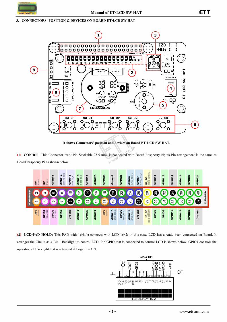
3. CONNECTORS’ POSITION & DEVICES ON BOARD ET-LCD SW HAT
It shows Connectors’ position and devices on Board ET-LCD SW HAT.
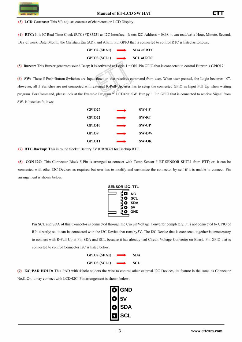
(1) CON-RPi: This Connector 2x20 Pin Stackable 25.5 mm. is connected with Board Raspberry Pi; its Pin arrangement is the same as Board Raspberry Pi as shown below. (2) LCD-PAD HOLD: This PAD with 16-hole connects with LCD 16x2; in this case, LCD has already been connected on Board. It arranges the Circuit as 4 Bit + Backlight to control LCD. Pin GPIO that is connected to control LCD is shown below. GPIO4 controls the operation of Backlight that is activated at Logic 1 = ON.
1
2
3
4
5
6
7
8
9
Manual of ET-LCD SW HAT
- 3 - www.etteam.com
(3) LCD-Contrast: This VR adjusts contrast of characters on LCD Display.
(4) RTC: It is IC Real Time Clock (RTC) #DS3231 as I2C Interface. It sets I2C Address = 0x68, it can read/write Hour, Minute, Second, Day of week, Date, Month, the Christian Era (AD), and Alarm. Pin GPIO that is connected to control RTC is listed as follows; GPIO2 (SDA1) SDA of RTC GPIO3 (SCL1) SCL of RTC (5) Buzzer: This Buzzer generates sound Beep; it is activated at Logic 1 = ON. Pin GPIO that is connected to control Buzzer is GPIO17.
(6) SW: These 5 Push-Button Switches are Input function that receives command from user. When user pressed, the Logic becomes “0”. However, all 5 Switches are not connected with external R-Pull-Up, user has to setup the connected GPIO as Input Pull Up when writing program. For Command, please look at the Example Program “ LCD4bit_SW_Buz.py ”. Pin GPIO that is connected to receive Signal from SW. is listed as follows; GPIO27 SW-LF GPIO22 SW-RT GPIO10 SW-UP GPIO9 SW-DW GPIO11 SW-OK (7) RTC-Backup: This is round Socket Battery 3V (CR2032) for Backup RTC.
(8) CON-I2C: This Connector Block 5-Pin is arranged to connect with Temp Sensor # ET-SENSOR SHT31 from ETT; or, it can be connected with other I2C Devices as required but user has to modify and customize the connector by self if it is unable to connect. Pin arrangement is shown below;
Pin SCL and SDA of this Connector is connected through the Circuit Voltage Converter completely, it is not connected to GPIO of RPi directly; so, it can be connected with the I2C Device that runs by5V. The I2C Device that is connected together is unnecessary to connect with R-Pull Up at Pin SDA and SCL because it has already had Circuit Voltage Converter on Board. Pin GPIO that is connected to control Connector I2C is listed below;
GPIO2 (SDA1) SDA GPIO3 (SCL1) SCL (9) I2C-PAD HOLD: This PAD with 4-hole solders the wire to control other external I2C Devices, its feature is the same as Connector No.8. Or, it may connect with LCD-I2C. Pin arrangement is shown below;
5V
GND
SCL
NC
SDA
SENSOR-I2C- TTL
5V
GND
SCL
SDA

Manual of ET-LCD SW HAT
- 4 - www.etteam.com
4. EXAMPLE PROGRAMS & HOW TO RUN PROGRAM
These 3 Example Programs are written by Python Language that covers the use of all I/O devices on Board; it is stored in the Folder name“ Ex_ET-LCD SW HAT /Ex_LCD_4Bit ”. The operation of each example program accords with section 4.1. For running this example program, please look at section 4.2 because it has to install some Library into Board Raspberry before running program. 4.1 EXAMPLE PROGRAMS There are 3 Example Programs that are provided with CD are written by Python Language, it covers the use of all I/O devices on Board. Each example program uses Function in the part of RPi.GPIO that is installed together with OS Raspbian-jessie; moreover, it has to additionally install the part of Library SMBUS because it includes the function of interfacing with I2C. The operation of each example program is described below; 1) LCD4bit_SW_Buz.py: This example illustrates how to control LCD as 4-Bit, Buzzer and reads value of all 5-SW; it will be called and used in the part of function Library RPi.GPIO only. The operation loops in the part of function main(); it loops and waits to receive the reading value of all 5-SW that is pressed. When any SW. is pressed (Logic=0), it generates sound Beep and displays name of the pressed SW. on LCD Display. When the SW. is released, the name of SW. on LCD Display disappears; and finally, it displays the message “Press SW.” instead. 2) LCD4bit_RTC3231.py: This example illustrates how to read/write RTC and display the result on the LCD Display. First of all, it has to ensure that OS has already installed Library SMBUS and I2C has already been enabled before running this example program, otherwise Error occurs while running. The operation loops in the part of Function main(). It starts the program by writing Time as 12:00:00 and Date 29/9/16 and stores in RTC first; next, it loops to read value of time and date from RTC and displays on the LCD Display. The upper line displays the value of Time and the lower line displays the value of Date. Please look at the value of Second, it always runs all the time. 3) LCD4bit_SHT31.py: This example program illustrates how to use Connector RTC as Block 5-Pin; it uses Temp Sensor #SHT31 from ETT. It can be connected on Board instantly because this Sensor Device is I2C Interface as same as RTC. First of all, it has to ensure that OS has already installed Library SMBUS and I2C has already been enabled, otherwise Error may occur while running. The operation loops in the part of Function main() as well. It starts the program by writing I2C Address to Sensor; next, it reads the value of temperature and humidity to store in the variable in order to calculate the actual value of temperature and humidity. And finally, it sends the result of calculating to display on the LCD Display; the upper line displays value of the temperature in the unit of Celsius (C) and the lower line displays percentage of the humidity (RH). 4.2 HOW TO RUN EXAMPLE PROGRAMS
When running this Example Program, it has to copy all example programs and then paste them in Micro SD that has already installed OS. If Error occurs while running program and it makes some programs cannot run; it may occur because of old version of OS, so it cannot find any function in Libary RPi.GPIO or SMBUS. In this case, it has to upgrade newer version of OS first; user can search Google to find how to upgrade newer version of OS by self. The example file is single file with surname .py; so, it is unnecessary to install any more Library, except RPI.GPIO (accompanied with OS) and SMBUS (additionally install). For Compiler Pyhon, it is provided with OS, so it is unnecessary to additionally install.
Before running example, it has to understand the operation of Board RPi well; in this case, there are 3 main types and user can choose the preferable type as follows; - Type 1: It is used as Remote Command Line (SSH) on Windows by Program PuTTy (in the Folder name “Tool / SSH_RemoteCommand_Rpi”). In this case, Board RPi and PC of user must be connected together in the same LAN and Router is used as intermediate. - Type 2: It is used as Remote Desktop (VNC) on Windows by Program TightVNCServer (in the folder name“Tool /
Manual of ET-LCD SW HAT
- 5 - www.etteam.com
VNC_RemoteDesktop_RPi”). In this case, Board RPi and PC of user must be connected together in the same LAN and Router is used as intermediate like Type 1. However, this Type 3 is different from Type 2 because it can be used and accessed by Desktop. - Type 3: It can be used and accessed by Board RPi directly; in this case, it has to connect Monitor at HDMI Channel, and connect Mouse
and Keyboard at USB Channel. Now, it can be used as a computer and Micro SD looks like Hard disk that has already installed OS of RPi; so, it can copy Files through USB Drive that is connected with Board RPi instantly.
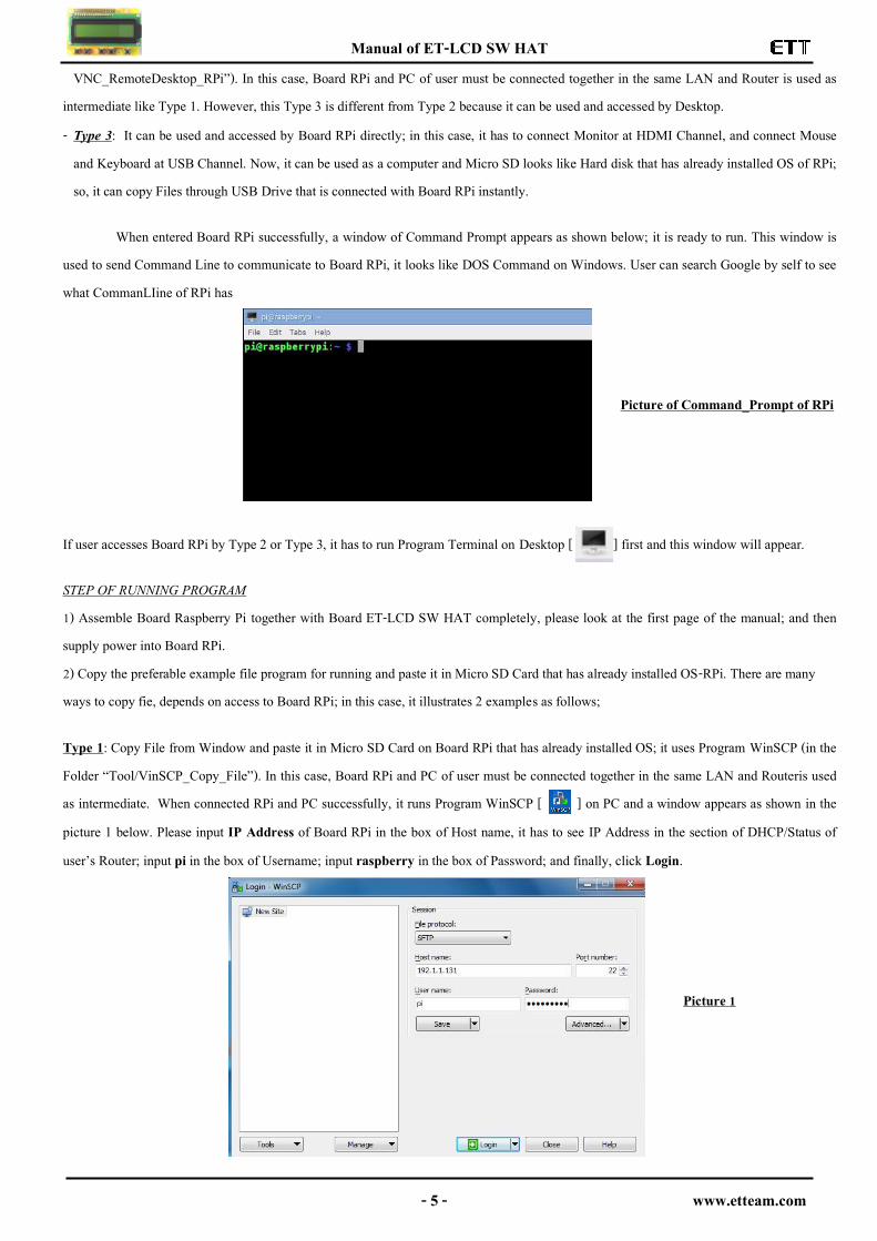
When entered Board RPi successfully, a window of Command Prompt appears as shown below; it is ready to run. This window is used to send Command Line to communicate to Board RPi, it looks like DOS Command on Windows. User can search Google by self to see what CommanLIine of RPi has
Picture of Command_Prompt of RPi
If user accesses Board RPi by Type 2 or Type 3, it has to run Program Terminal on Desktop [ ] first and this window will appear.
STEP OF RUNNING PROGRAM 1) Assemble Board Raspberry Pi together with Board ET-LCD SW HAT completely, please look at the first page of the manual; and then supply power into Board RPi. 2) Copy the preferable example file program for running and paste it in Micro SD Card that has already installed OS-RPi. There are many ways to copy fie, depends on access to Board RPi; in this case, it illustrates 2 examples as follows;
Type 1: Copy File from Window and paste it in Micro SD Card on Board RPi that has already installed OS; it uses Program WinSCP (in the Folder “Tool/VinSCP_Copy_File”). In this case, Board RPi and PC of user must be connected together in the same LAN and Routeris used as intermediate. When connected RPi and PC successfully, it runs Program WinSCP [ ] on PC and a window appears as shown in the picture 1 below. Please input IP Address of Board RPi in the box of Host name, it has to see IP Address in the section of DHCP/Status of user’s Router; input pi in the box of Username; input raspberry in the box of Password; and finally, click Login.
Picture 1
Manual of ET-LCD SW HAT
- 6 - www.etteam.com
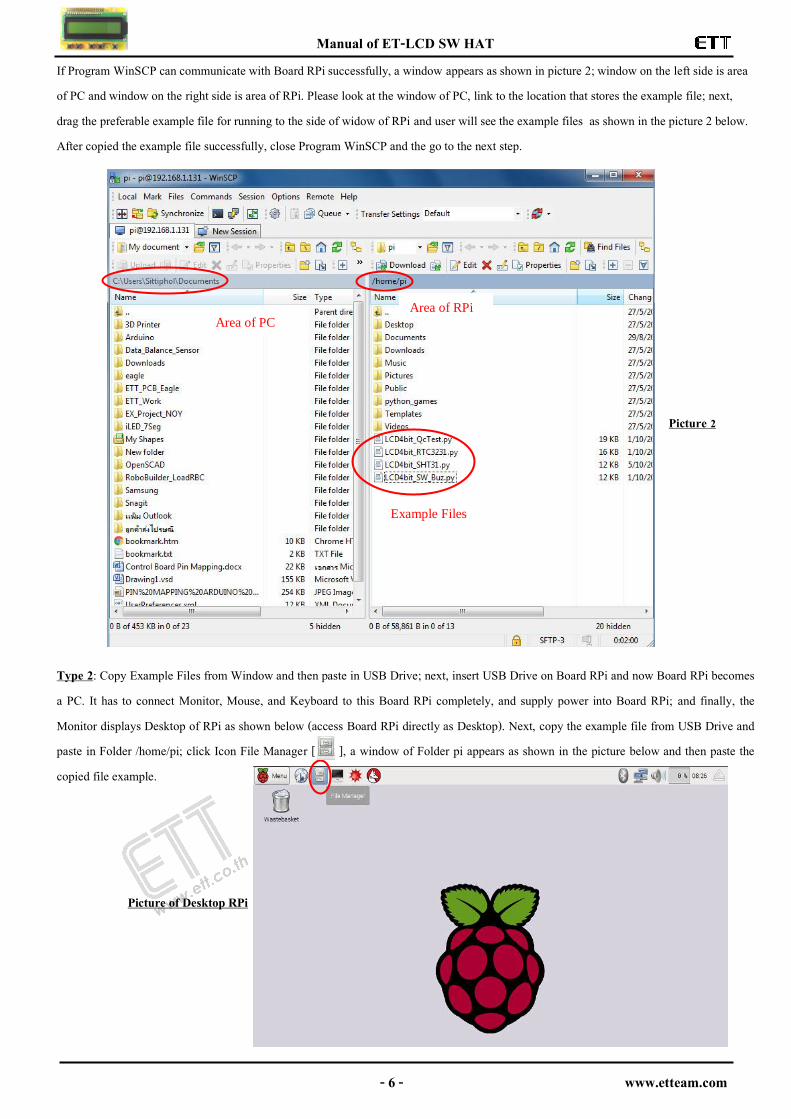
If Program WinSCP can communicate with Board RPi successfully, a window appears as shown in picture 2; window on the left side is area of PC and window on the right side is area of RPi. Please look at the window of PC, link to the location that stores the example file; next, drag the preferable example file for running to the side of widow of RPi and user will see the example files as shown in the picture 2 below. After copied the example file successfully, close Program WinSCP and the go to the next step.
Picture 2
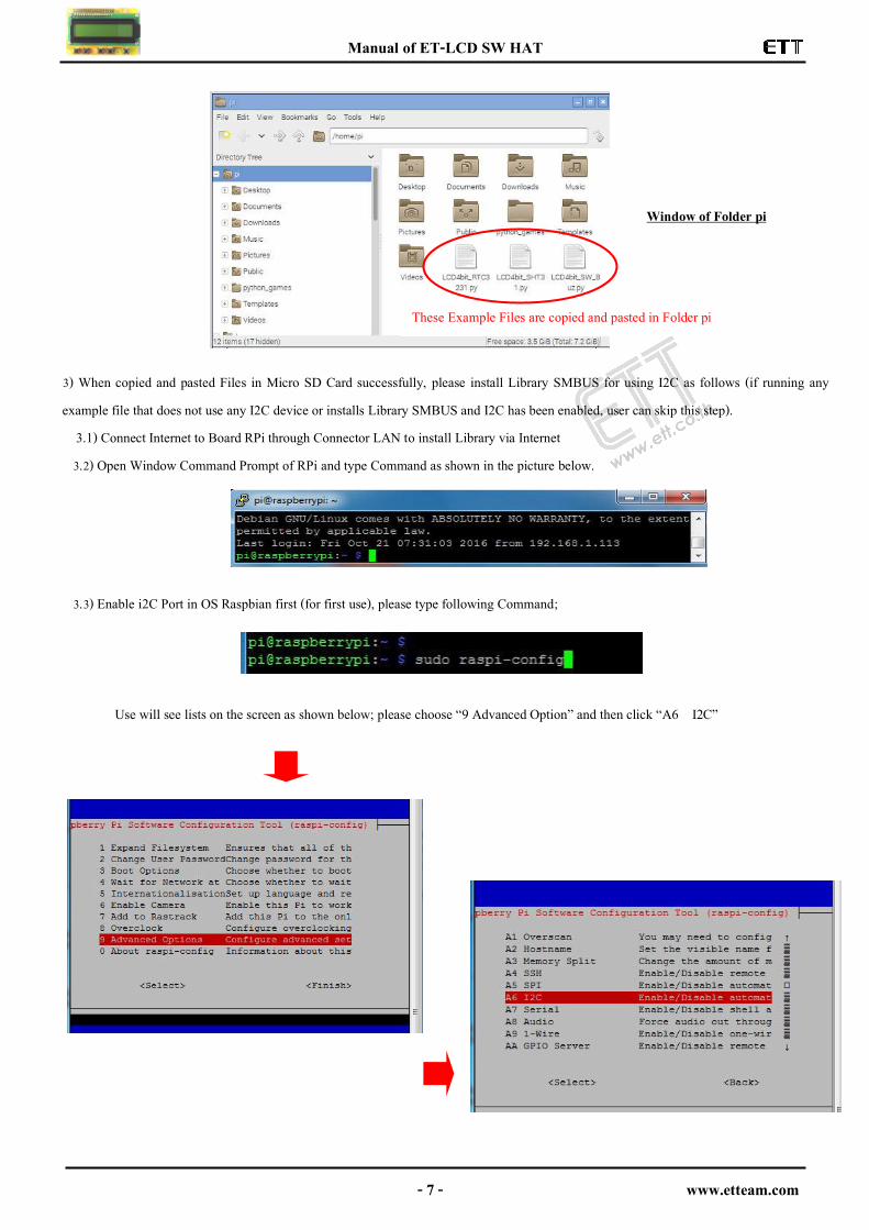
Type 2: Copy Example Files from Window and then paste in USB Drive; next, insert USB Drive on Board RPi and now Board RPi becomes a PC. It has to connect Monitor, Mouse, and Keyboard to this Board RPi completely, and supply power into Board RPi; and finally, the Monitor displays Desktop of RPi as shown below (access Board RPi directly as Desktop). Next, copy the example file from USB Drive and paste in Folder /home/pi; click Icon File Manager [ ], a window of Folder pi appears as shown in the picture below and then paste the copied file example. Picture of Desktop RPi
Area of PC Area of RPi
Example Files
Manual of ET-LCD SW HAT
- 7 - www.etteam.com
Window of Folder pi 3) When copied and pasted Files in Micro SD Card successfully, please install Library SMBUS for using I2C as follows (if running any example file that does not use any I2C device or installs Library SMBUS and I2C has been enabled, user can skip this step). 3.1) Connect Internet to Board RPi through Connector LAN to install Library via Internet 3.2) Open Window Command Prompt of RPi and type Command as shown in the picture below.
3.3) Enable i2C Port in OS Raspbian first (for first use), please type following Command;
Use will see lists on the screen as shown below; please choose “9 Advanced Option” and then click “A6 I2C”
These Example Files are copied and pasted in Folder pi
Manual of ET-LCD SW HAT
- 8 - www.etteam.com
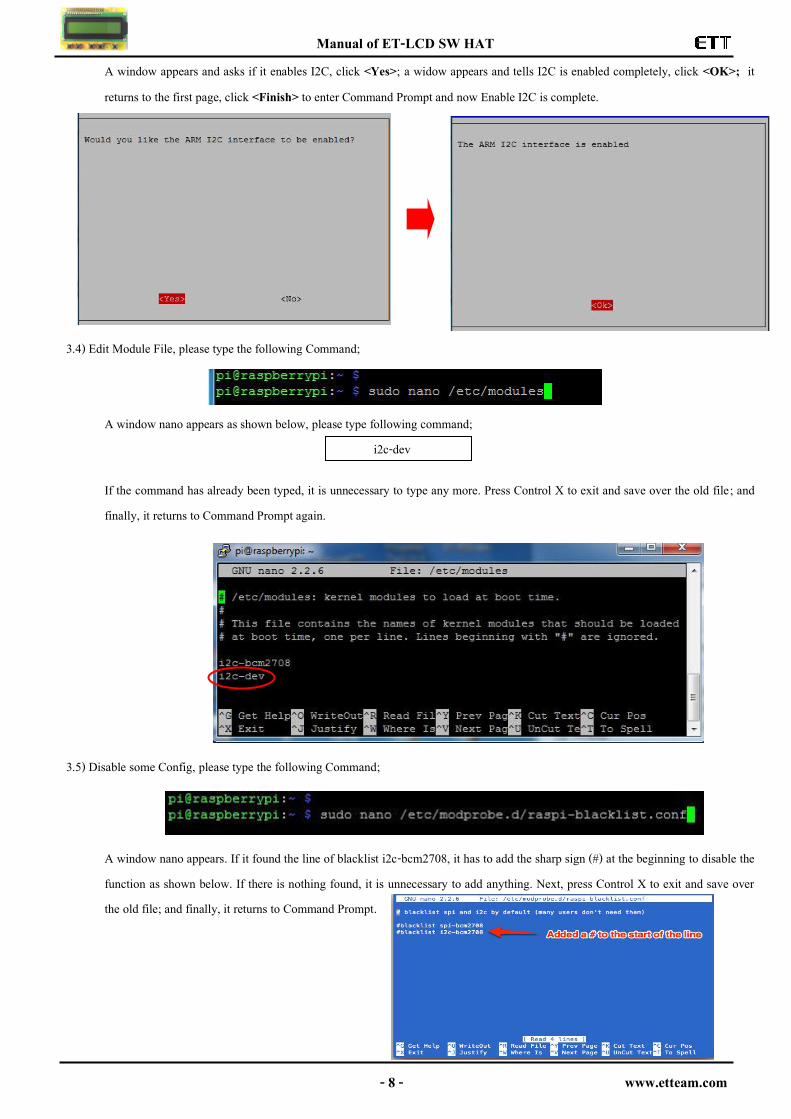
A window appears and asks if it enables I2C, click <Yes>; a widow appears and tells I2C is enabled completely, click <OK>; it returns to the first page, click <Finish> to enter Command Prompt and now Enable I2C is complete.
3.4) Edit Module File, please type the following Command;
A window nano appears as shown below, please type following command; i2c-dev
If the command has already been typed, it is unnecessary to type any more. Press Control X to exit and save over the old file; and finally, it returns to Command Prompt again.
3.5) Disable some Config, please type the following Command;
A window nano appears. If it found the line of blacklist i2c-bcm2708, it has to add the sharp sign (#) at the beginning to disable the function as shown below. If there is nothing found, it is unnecessary to add anything. Next, press Control X to exit and save over the old file; and finally, it returns to Command Prompt.
Manual of ET-LCD SW HAT
- 9 - www.etteam.com
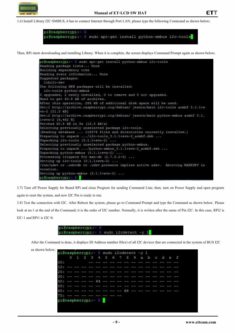
3.6) Install Library I2C-SMBUS, it has to connect Internet through Port LAN, please type the following Command as shown below;
Then, RPi starts downloading and installing Library. When it is complete, the screen displays Command Prompt again as shown below; 3.7) Turn off Power Supply for Board RPi and close Program for sending Command Line; then, turn on Power Supply and open program again to reset the system, and now I2C Pin is ready to run. 3.8) Test the connection with I2C. After Reboot the system, please go to Command Prompt and type the Command as shown below. Please look at no.1 at the end of the Command; it is the order of I2C number. Normally, it is written after the name of Pin I2C. In this case, RPi2 is I2C-1 and RPi1 is I2C-0.
After the Command is done, it displays ID Address number (Hex) of all I2C devices that are connected in the system of BUS I2C as shown below;
Manual of ET-LCD SW HAT
- 10 - www.etteam.com
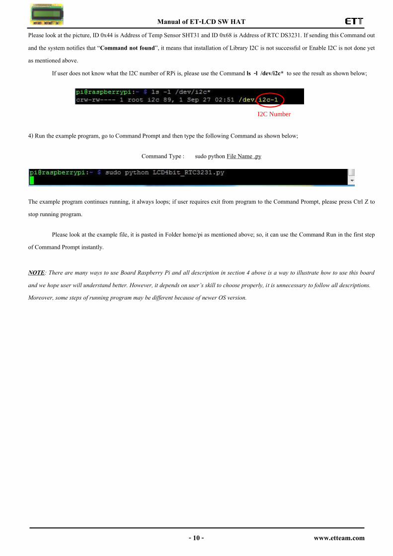
Please look at the picture, ID 0x44 is Address of Temp Sensor SHT31 and ID 0x68 is Address of RTC DS3231. If sending this Command out and the system notifies that “Command not found”, it means that installation of Library I2C is not successful or Enable I2C is not done yet as mentioned above.
If user does not know what the I2C number of RPi is, please use the Command ls -l /dev/i2c* to see the result as shown below; 4) Run the example program, go to Command Prompt and then type the following Command as shown below;
Command Type : sudo python File Name .py
The example program continues running, it always loops; if user requires exit from program to the Command Prompt, please press Ctrl Z to stop running program.
Please look at the example file, it is pasted in Folder home/pi as mentioned above; so, it can use the Command Run in the first step of Command Prompt instantly. NOTE: There are many ways to use Board Raspberry Pi and all description in section 4 above is a way to illustrate how to use this board and we hope user will understand better. However, it depends on user’s skill to choose properly, it is unnecessary to follow all descriptions. Moreover, some steps of running program may be different because of newer OS version.
I2C Number
Manual of ET-LCD SW HAT
- 11 - www.etteam.com
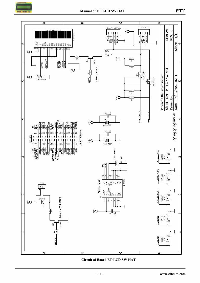
วงจร
Circuit of Board ET-LCD SW HAT