estun edb users manual.pdf
TRANSCRIPT
1
EDB series AC servo system User’s Manual V. 2.00
Anaheim Automation Limited Warranty This manual does not entitle you to any rights. Anaheim Automation reserves the right to change this manual without prior notice. All rights reserved. No part of this publication may be copied or reproduced without written permission from Anaheim Automation.
2
General Precautions
Voltage of power supply is 200V Please connect to 200V voltage electrical source
Don’t connect Servomotor directly to the residential electric network. Do not connect Servomotor directly to the residential electric network; otherwise, it will be damaged.
Servomotor is not able to work without relevant Servo drive.
Don’t plug or unplug the electric socket when power is ON. Always turn the power OFF before plug or unplug to the electric socket.
Wait at least five minutes before inspection after turning OFF power Note that even when the power is turned off, there will still be residual voltage remained in the capacitor. In
order to avoid electrical shock, please make sure the Charge lamp is OFF before inspection.
The installation interval to other equipment is above 10mm. The installation interval to other equipment should be at least 10mm breadthways and 50mm lengthways.
The Servo drive generates heat, please layout the Installation the Servo drive which is good to radiate heat.
Please install the Servo drive in an environment free from condensation, vibration and shock.
Please take treatment of anti-disturbance and grounding properly. If there are disturbance in the signal line, vibration or malfunction will likely occur.
Please stick to the following rules strictly:
1. Separate high-voltage cable from low-voltage cable.
2. Make cables as short as possible
3. Apply one phase grounding (ground resistance less than 100Ω) for the installation of Servomotor and
Servo drive.
4. NO power input noise filter between servo drive and servomotor.
Please conduct voltage endurance under following conditions: 5. Voltage: AC 1500Vrms, 1 min
6. Cut the current: 100mA
7. Frequency: 50/60Hz
8. Voltage applied point: L1, L2, L3 pins and FG tie-in (Please fast the connection among terminals). Creepage prevention instrument: please select quick-response type
For a ground-fault interrupter, always use a quick response type or one designed for PWM inverters. Do not
use a time-delay type.
Don’t perform continuous operation under overhanging load. Continuous operation cannot be performed by rotating the motor from the load and applying regenerative
braking. Regenerative braking by the Servo drive can be applied only for a short period, such as the motor
deceleration time.
Turning the Power On and Power Off frequently will result in speeding up deterioration of internal elements.
Please control the servo motor with reference signals.
3
Content Chapter 1 .......................................................................................................................................................................... 6 Checking products and parts names .................................................................................................................................. 6
1. 1 Check products ..................................................................................................................................................... 6 1.1.1 Servo drive ........................................................................................................................... 7
1.2 Product Parts names ..................................................................................................................................... 8 1.2.1 Servo drive ..................................................................................................................................................... 8
Chapter 2 .......................................................................................................................................................................... 9 Installation ........................................................................................................................................................................... 9
2.1 Servodrive ............................................................................................................................................................. 9 2.2.1 Storage ................................................................................................................................. 9 2.2.2 Installation sites .................................................................................................................... 9 2.2.3 Installation orientation ........................................................................................................ 10 2.2.4 Installation method ............................................................................................................. 10
Chapter 3 .......................................................................................................................................................................... 11 Wirings and connections ................................................................................................................................................... 11
3.1 Wirings and connections for main circuit ............................................................................................................ 11 3.1.1 Names and Functions of Main Circuit Terminals ............................................................... 11 3.1.2 Typical main circuit wiring example ................................................................................... 12
3.2 Input and output signal ........................................................................................................................................ 12 3.2 Input and output signal ........................................................................................................................................ 13 3.2.1 Connection of input and output signals ............................................................................................................ 13
3.2.2 Terminal layout of connector 1CN ..................................................................................... 14 3.2.3 I/O signal names and functions ......................................................................................... 15 3.2.4 Interface Circuit .................................................................................................................. 17
3.3 wiring encoders ................................................................................................................................................... 18 3.3.1 Connecting an Encoder (2CN) and Output Signals from the servodrive ........................................................ 18
3.3.2 Encoder Connector (CN2) Terminal Layout ...................................................................... 18 3.4 Wiring servo motor .............................................................................................................................................. 19
3.4.1 Encoder Connector Terminal Layout ............................................................................. 19 3.4.2 Dynamic power Connector Terminal layout ...................................................................... 19
3.5 Typical wiring example ........................................................................................................................................ 20 3.5.1 Position control mode ....................................................................................................................................... 20 3.5.1 Position control mode ....................................................................................................................................... 21
3.5.2 Speed control mode ...................................................................................................... 22 3.5.3 Torque control mode ..................................................................................................... 23
Chapter 4 .......................................................................................................................................................................... 24 Parameter Setting and function description ..................................................................................................................... 24
4.1 Setting Parameters according to mechanical features ....................................................................................... 24 4.1.1 Changing the Direction of Motor Rotation ......................................................................... 24
Select the rotating direction by setting parameters below: ....................................................................................... 24 4.1.2 Setting overtravel limit .................................................................................................. 25 4.1.3 Limiting Torque ............................................................................................................. 26
4
4.2 Setting Parameters According to Host Controller ............................................................................................... 29 4.2.1 Speed Reference ............................................................................................................... 29 4.2.2 Position reference .............................................................................................................. 34 4.2.3 Encoder signal output .................................................................................................... 38 4.2.4 Contact I/O Signals ...................................................................................................... 41 4.2.5 Position control (parameter reference) .............................................................................. 42 4.2.7 Using Contact Input Speed Control ................................................................................... 50 4.2.8 Using Torque Control ......................................................................................................... 54 4.2.9 Using Torque Feed-forward Function ................................................................................ 59 4.2.10 Using Torque Restriction by Analog Voltage Reference ................................................. 60 4.2.11 Using the Reference Pulse Inhibit Function (INHIBIT) .................................................... 62
4.3 Setting up the parameter ............................................................................................................................. 64 4.3.1 Setting the Jog Speed ........................................................................................................ 64 4.3.2 Selecting the control modes .............................................................................................. 64
4.4 Setting Stop Mode ............................................................................................................................................... 72 4.4.1 Adjusting Offset .................................................................................................................. 72 4.4.2 Using Dynamic Brake ........................................................................................................ 72 4.4.3 Using Zero-Clamp .............................................................................................................. 73 4.4.4 Using Holding Brake .......................................................................................................... 75
4.5 Forming a Protective Sequence .......................................................................................................................... 79 4.5.1 Using Servo Alarm Output and Alarm Code Output .......................................................... 79 4.5.2 Using Servo ON Input Signal ............................................................................................. 80 4.5.3 Using Positioning Complete Signal ................................................................................... 81 4.5.4 Using Speed Coincidence Output Signal .......................................................................... 83 4.5.5 Using Running Output Signal ............................................................................................ 84 4.5.6 Using Servo Ready Output Signal ..................................................................................... 85 4.5.7 Handling of Power Loss ..................................................................................................... 87 4.5.8 Using Regenerative Resistor Units .................................................................................... 88
4.6 Running the Motor Smoothly ............................................................................................................................... 88 4.6.1 Using Smoothing function .................................................................................................. 88 4.6.2 Using the Soft Start Function ............................................................................................. 89 4.6.3 Setting the Torque Reference Filter Time Constant .......................................................... 90 4.7 Minimizing Positioning Time ................................................................................................. 90 4.7.1 Setting Servo Gain ............................................................................................................. 90 4.7.2 Using Proportional Control ................................................................................................. 91 4.7.3 Setting Speed Bias ............................................................................................................ 92
Chapter 5 .......................................................................................................................................................................... 93 Using the digital operator .................................................................................................................................................. 93
5.1 Basic operator ..................................................................................................................................................... 93 5.1.1 Digital Operator Functions ................................................................................................. 93 5.1.2 Resetting Servo Alarms ..................................................................................................... 93 5.1.3 Basic Functions and Mode Selection ................................................................................ 94 5.1.4 Operation in Status Display Mode ..................................................................................... 94 5.1.5 Operation in Parameter Setting Mode ............................................................................... 97
5
5.1.6 Operation in Monitor Mode ................................................................................................ 97 Operation Using the Digital Operator ........................................................................................................................ 99
5.2.1 Alarm Trace-back Data .................................................................................................... 100 5.2.2 Operation of recovering to default value .......................................................................... 100 5.2.3 Operation in JOG mode ................................................................................................... 101 5.2.4 Reference Offset Automatic Adjustment ......................................................................... 101 5.2.5 Reference Offset Manual Adjustment Mode ................................................................... 103 5.2.6 Motor Current Detection Offset Adjustment .................................................................... 103 5.2.7 Checking Software Version ............................................................................................. 106
Chapter 6 ........................................................................................................................................................................ 107 Communication functions ............................................................................................................................................... 107
6.1 RS-485、RS-232、RS-422 Communication hardware interface ............................................................. 107
6.2 RS-485、RS-232、RS-422 communication parameter ........................................................................... 108
6.3 MODBUS communication protocol ........................................................................................................... 110 6.3.1 Code meaning ............................................................................................................ 110 6.3.2 Communication fault disposal .................................................................................... 115 6.3.3 Servo state data communication address ................................................................. 117
Chapter 7 ........................................................................................................................................................................ 120 Technical Specifications and Features ........................................................................................................................... 120
7.1 Servomotor Technical specifications and Types .............................................................................................. 120 7.2 Servo Drive Mounting dimension ........................................................................................ 123
Appendix A ...................................................................................................................................................................... 124 Parameter list .................................................................................................................................................................. 124 Appendix B ...................................................................................................................................................................... 136
6
Chapter 1
Checking products and parts names
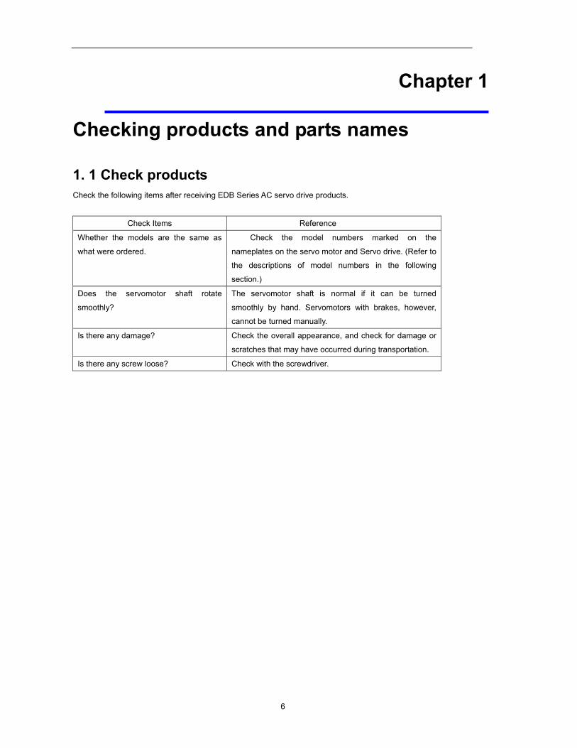
1. 1 Check products Check the following items after receiving EDB Series AC servo drive products.
Check Items Reference
Whether the models are the same as
what were ordered.
Check the model numbers marked on the
nameplates on the servo motor and Servo drive. (Refer to
the descriptions of model numbers in the following
section.)
Does the servomotor shaft rotate
smoothly?
The servomotor shaft is normal if it can be turned
smoothly by hand. Servomotors with brakes, however,
cannot be turned manually.
Is there any damage? Check the overall appearance, and check for damage or
scratches that may have occurred during transportation.
Is there any screw loose? Check with the screwdriver.
7
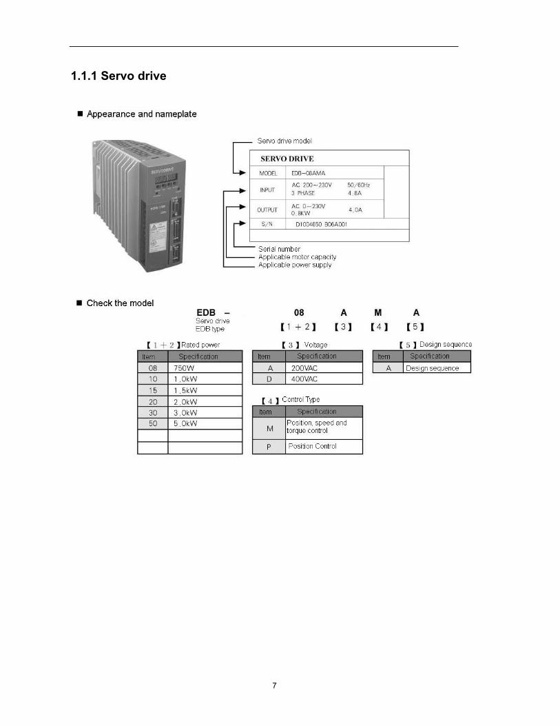
1.1.1 Servo drive
8
Panel display
1.2 Product Parts names
1.2.1 Servo drive
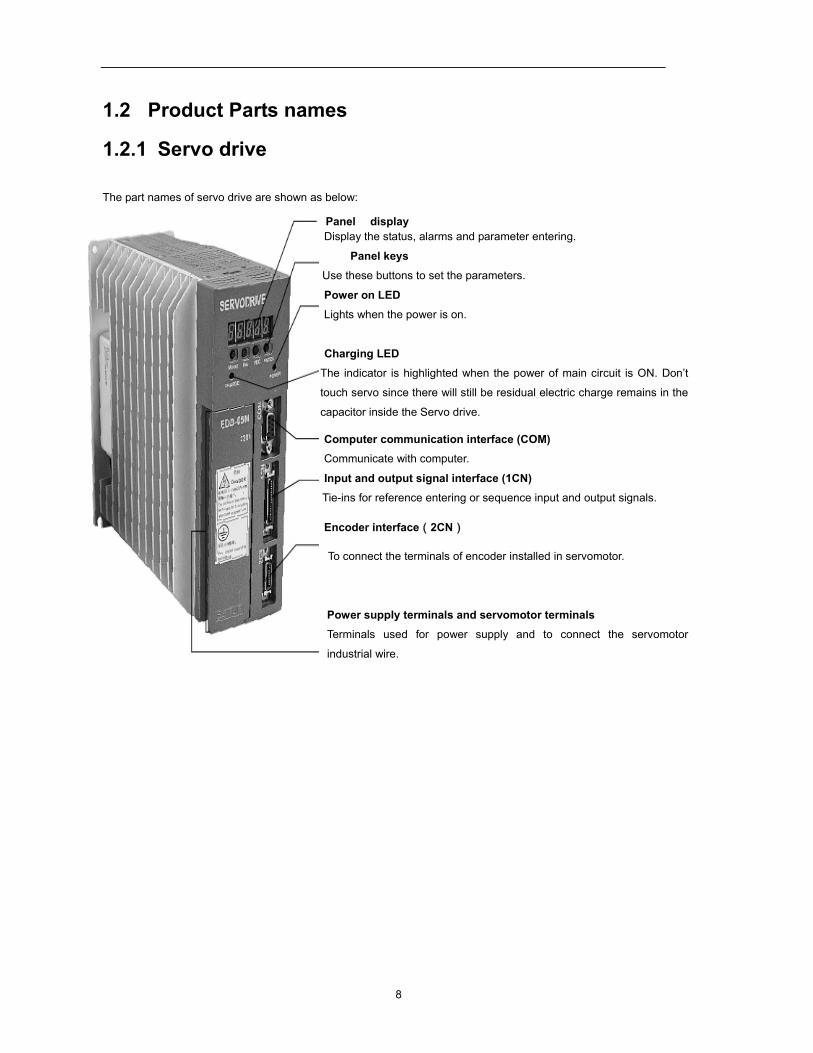
The part names of servo drive are shown as below:
Display the status, alarms and parameter entering.
Panel keys
Use these buttons to set the parameters.
Power on LED Lights when the power is on.
Charging LED The indicator is highlighted when the power of main circuit is ON. Don’t
touch servo since there will still be residual electric charge remains in the
capacitor inside the Servo drive.
Computer communication interface (COM) Communicate with computer.
Input and output signal interface (1CN) Tie-ins for reference entering or sequence input and output signals.
Encoder interface(2CN)
To connect the terminals of encoder installed in servomotor.
Power supply terminals and servomotor terminals Terminals used for power supply and to connect the servomotor
industrial wire.
9
Chapter 2
Installation
2.1 Servodrive EDB Series Servo drive is a base-mounted type servo controller. Incorrect installation will cause problems. Always
observe the installation instructions described below.
2.2.1 Storage
When the Servo drive is to be stored with the power cable disconnected, store it in the following temperature range:
Between −20°C and 85°C
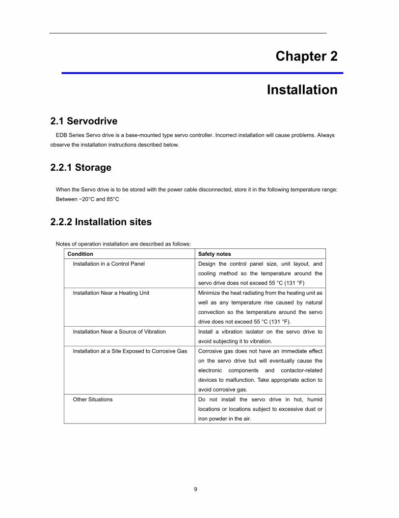
2.2.2 Installation sites
Notes of operation installation are described as follows:
Condition Safety notes
Installation in a Control Panel Design the control panel size, unit layout, and
cooling method so the temperature around the
servo drive does not exceed 55 °C (131 °F)
Installation Near a Heating Unit Minimize the heat radiating from the heating unit as
well as any temperature rise caused by natural
convection so the temperature around the servo
drive does not exceed 55 °C (131 °F).
Installation Near a Source of Vibration Install a vibration isolator on the servo drive to
avoid subjecting it to vibration.
Installation at a Site Exposed to Corrosive Gas Corrosive gas does not have an immediate effect
on the servo drive but will eventually cause the
electronic components and contactor-related
devices to malfunction. Take appropriate action to
avoid corrosive gas.
Other Situations Do not install the servo drive in hot, humid
locations or locations subject to excessive dust or
iron powder in the air.
10
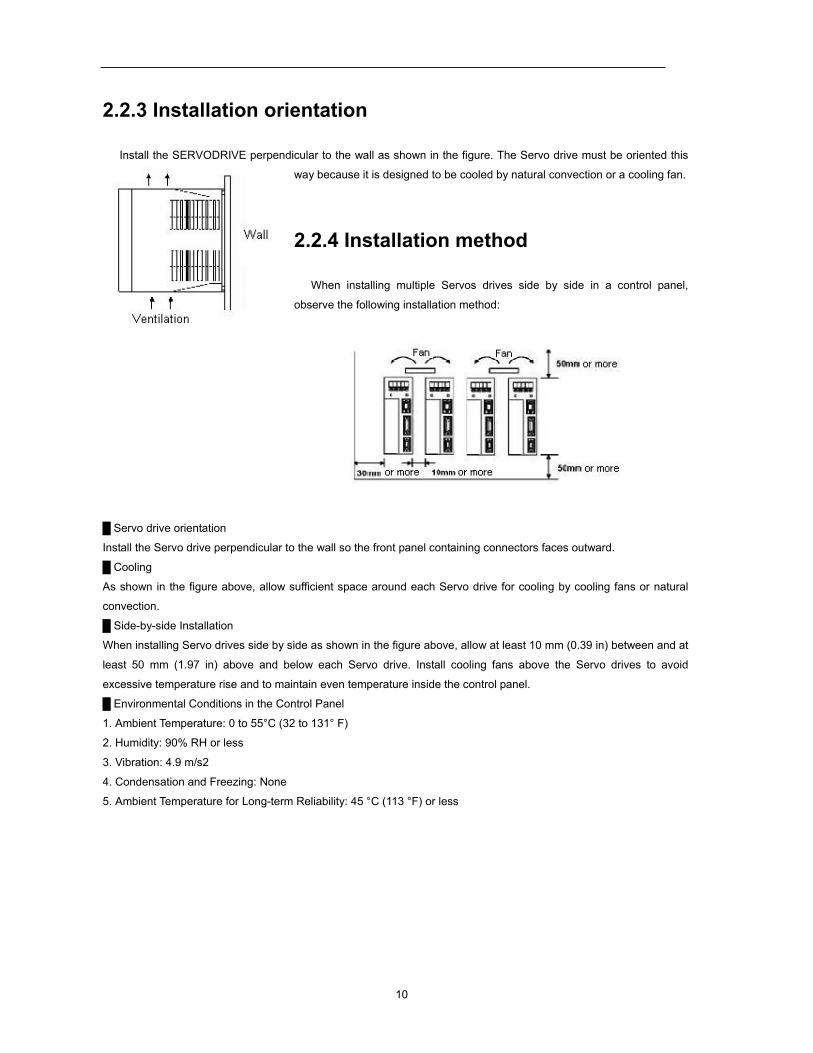
2.2.3 Installation orientation
Install the SERVODRIVE perpendicular to the wall as shown in the figure. The Servo drive must be oriented this
way because it is designed to be cooled by natural convection or a cooling fan.
2.2.4 Installation method
When installing multiple Servos drives side by side in a control panel,
observe the following installation method:
Servo drive orientation
Install the Servo drive perpendicular to the wall so the front panel containing connectors faces outward.
Cooling
As shown in the figure above, allow sufficient space around each Servo drive for cooling by cooling fans or natural
convection.
Side-by-side Installation When installing Servo drives side by side as shown in the figure above, allow at least 10 mm (0.39 in) between and at
least 50 mm (1.97 in) above and below each Servo drive. Install cooling fans above the Servo drives to avoid
excessive temperature rise and to maintain even temperature inside the control panel.
Environmental Conditions in the Control Panel 1. Ambient Temperature: 0 to 55°C (32 to 131° F)
2. Humidity: 90% RH or less
3. Vibration: 4.9 m/s2
4. Condensation and Freezing: None
5. Ambient Temperature for Long-term Reliability: 45 °C (113 °F) or less
11
Chapter 3
Wirings and connections
3.1 Wirings and connections for main circuit Always observe the following notes when wire or connects the circuit.
Do not wire power lines and signal lines in the same duct or bundle them together. Wire
such that signal lines are kept apart from power lines by at least 30 cm. Twisted pair wire and multi-core twisted pair shielding wires should be used for signal
lines, encoder (PG) feedback line. The length for wiring is 3m maximum for the reference input line, 20 m maximum for the PG
feedback line.
Do not touch the power terminal even if power is turned off. High voltage may still remain in Servo drive. Perform inspection only after the CHARGE LED
extinct.
Avoid frequently turning the power ON and OFF with the interval at least more than 1 min. Since the Servo drive has a capacitor in the power supply, a high charging current flows (for 0.2
second) when the power is turned ON. Therefore, frequently turning the power ON and OFF
causes the main circuit devices (such as capacitors and fuses) to deteriorate, resulting in
unexpected problems.
3.1.1 Names and Functions of Main Circuit Terminals
Terminal symbol Name Description
L1,L2,L3 Main circuit power supply input
terminal Three-phase 200-230VAC
50/60HZ
L1C, L2C Control circuit power supply input
terminal Single-phase 200-230VAC
50/60HZ
U,V,W Servo Motor connection terminals Connects to servo motor
Ground terminals Connects to the power supply ground
terminals and servo motor ground
terminal.
B1, B2, B3 (EDB-08,
EDB-10, and
Regenerative resistor connection
terminal
Normally short B2 and B3 (for an internal
regenerative resistor). Remove the wire
12
EDB-15 don’t have
B3 terminal.)
between B2 and B3 and connect an
external regenerative resistor between B1
and B2 if the capacity of the internal
regenerative resistor is insufficient.
1 2 (EDB-08, EDB-10
And EDB-15 doesn’t
have those two
terminals.)
DC reactor for harmonic
suppression terminal
Normally short 1 and 2. If a countermeasure against power supply
harmonic waves is needed, connect a DC
reactor between 1 and 2.
(EDB-08, EDB-10 And EDB-15
doesn’t have this
terminal.)
Main circuit minus terminal
Normally not connected.
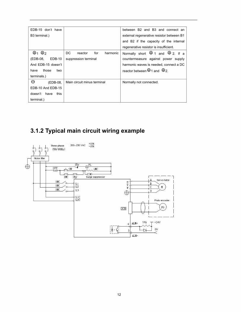
3.1.2 Typical main circuit wiring example
13
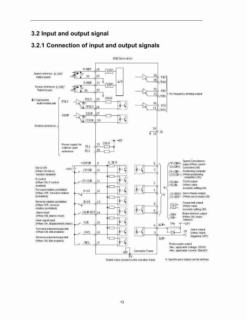
3.2 Input and output signal
3.2.1 Connection of input and output signals
14
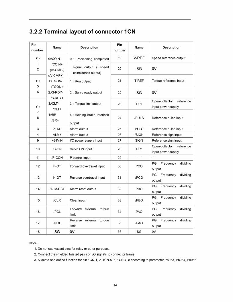
3.2.2 Terminal layout of connector 1CN
Pin
number Name Description
Pin
number Name Description
(*)
1
2
0:/COIN-
/COIN+
(/V-CMP-)
(/V-CMP+)
1:/TGON-
/TGON+
2:/S-RDY-
/S-RDY+
3:/CLT-
/CLT+
4:/BR-
/BR+
0: Positioning completed
signal output ( speed
coincidence output)
1:Run output
2:Servo ready output
3:Torque limit output
4:Holding brake interlock
output
19 V-REF Speed reference output
20 SG 0V
(*)
5
6
21 T-REF Torque reference input
22 SG 0V
(*)
7
8
23 PL1 Open-collector reference
input power supply
24 /PULS Reference pulse input
3 ALM- Alarm output 25 PULS Reference pulse input
4 ALM+ Alarm output 26 /SIGN Reference sign input
9 +24VIN I/O power supply input 27 SIGN Reference sign input
10 /S-ON Servo ON input 28 PL2 Open-collector reference
input power supply
11 /P-CON P control input 29 — —
12 P-OT Forward overtravel input 30 PCO PG Frequency dividing
output
13 N-OT Reverse overtravel input 31 /PCO PG Frequency dividing
output
14 /ALM-RST Alarm reset output 32 PBO PG Frequency dividing
output
15 /CLR Clear input 33 /PBO PG Frequency dividing
output
16 /PCL Forward external torque
limit 34 PAO
PG Frequency dividing
output
17 /NCL Reverse external torque
limit 35 /PAO
PG Frequency dividing
output
18 SG 0V 36 SG 0V
Note: 1. Do not use vacant pins for relay or other purposes.
2. Connect the shielded twisted pairs of I/O signals to connector frame.
3. Allocate and define function for pin 1CN-1, 2, 1CN-5, 6, 1CN-7, 8 according to parameter Pn053, Pn054, Pn055.
15
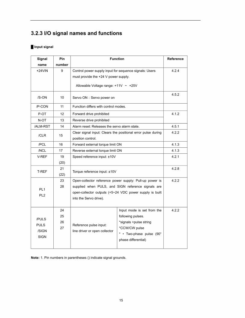
3.2.3 I/O signal names and functions
Input signal
Signal
name
Pin
number
Function Reference
+24VIN 9 Control power supply input for sequence signals: Users
must provide the +24 V power supply.
Allowable Voltage range: +11V ~ +25V
4.2.4
/S-ON 10 Servo ON:Servo power on 4.5.2
/P-CON 11 Function differs with control modes.
P-OT 12 Forward drive prohibited 4.1.2
N-OT 13 Reverse drive prohibited
/ALM-RST 14 Alarm reset: Releases the servo alarm state. 4.5.1
/CLR 15 Clear signal input: Clears the positional error pulse during
position control.
4.2.2
/PCL 16 Forward external torque limit ON 4.1.3
/NCL 17 Reverse external torque limit ON 4.1.3
V-REF 19
(20)
Speed reference input: ±10V 4.2.1
T-REF 21
(22) Torque reference input: ±10V
4.2.8
PL1
PL2
23
28
Open-collector reference power supply: Pull-up power is
supplied when PULS, and SIGN reference signals are
open-collector outputs (+5~24 VDC power supply is built
into the Servo drive).
4.2.2
/PULS
PULS
/SIGN
SIGN
24
25
26
27 Reference pulse input:
line driver or open collector
Input mode is set from the
following pulses.
*signals +pulse string
*CCW/CW pulse
* • Two-phase pulse (90°
phase differential)
4.2.2
Note: 1. Pin numbers in parentheses () indicate signal grounds.
16
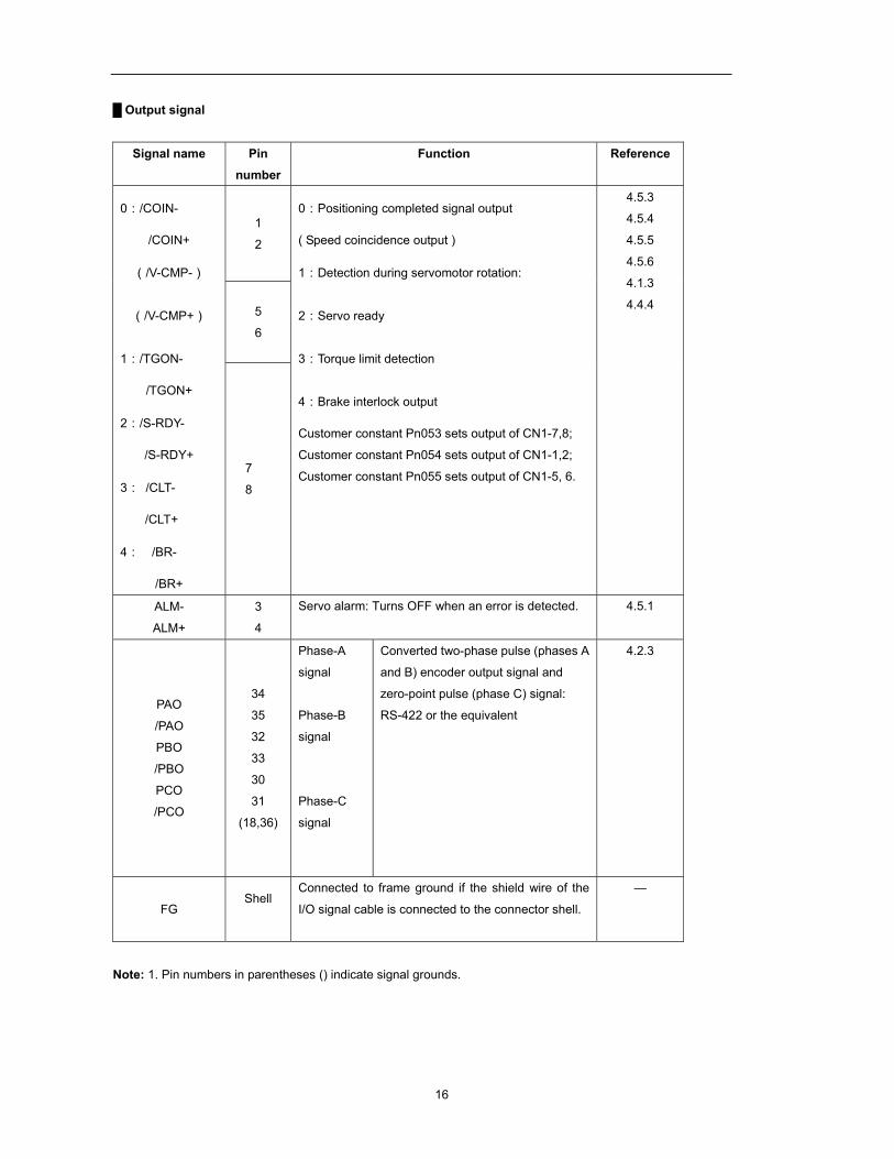
Output signal
Signal name Pin number
Function Reference
0:/COIN-
/COIN+
(/V-CMP-)
(/V-CMP+)
1:/TGON-
/TGON+
2:/S-RDY-
/S-RDY+
3: /CLT-
/CLT+
4: /BR-
/BR+
1
2
0:Positioning completed signal output
( Speed coincidence output )
1:Detection during servomotor rotation:
2:Servo ready
3:Torque limit detection
4:Brake interlock output
Customer constant Pn053 sets output of CN1-7,8;
Customer constant Pn054 sets output of CN1-1,2;
Customer constant Pn055 sets output of CN1-5, 6.
4.5.3
4.5.4
4.5.5
4.5.6
4.1.3
4.4.4 5
6
7
8
ALM-
ALM+
3
4
Servo alarm: Turns OFF when an error is detected.
4.5.1
PAO
/PAO
PBO
/PBO
PCO
/PCO
34
35
32
33
30
31
(18,36)
Phase-A
signal
Phase-B
signal
Phase-C
signal
Converted two-phase pulse (phases A
and B) encoder output signal and
zero-point pulse (phase C) signal:
RS-422 or the equivalent
4.2.3
FG Shell
Connected to frame ground if the shield wire of the
I/O signal cable is connected to the connector shell.
—
Note: 1. Pin numbers in parentheses () indicate signal grounds.
17
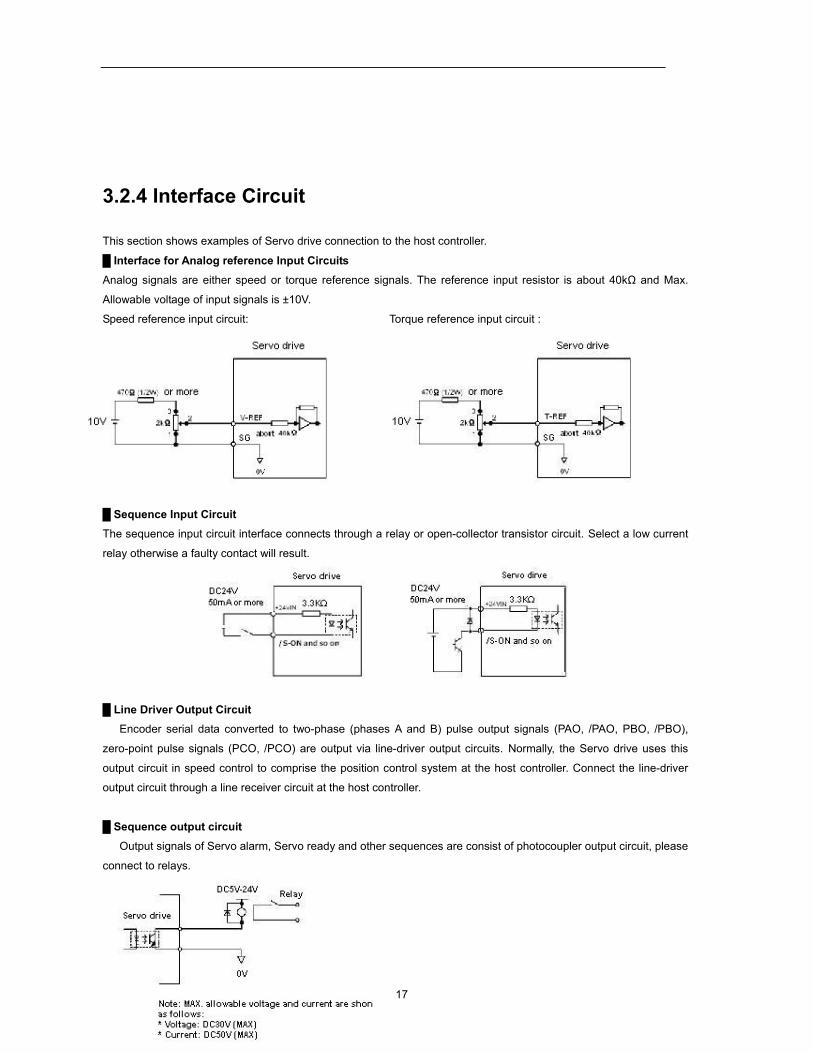
3.2.4 Interface Circuit
This section shows examples of Servo drive connection to the host controller.
Interface for Analog reference Input Circuits Analog signals are either speed or torque reference signals. The reference input resistor is about 40kΩ and Max.
Allowable voltage of input signals is ±10V.
Speed reference input circuit: Torque reference input circuit :
Sequence Input Circuit The sequence input circuit interface connects through a relay or open-collector transistor circuit. Select a low current
relay otherwise a faulty contact will result.
Line Driver Output Circuit Encoder serial data converted to two-phase (phases A and B) pulse output signals (PAO, /PAO, PBO, /PBO),
zero-point pulse signals (PCO, /PCO) are output via line-driver output circuits. Normally, the Servo drive uses this
output circuit in speed control to comprise the position control system at the host controller. Connect the line-driver
output circuit through a line receiver circuit at the host controller.
Sequence output circuit Output signals of Servo alarm, Servo ready and other sequences are consist of photocoupler output circuit, please
connect to relays.
18
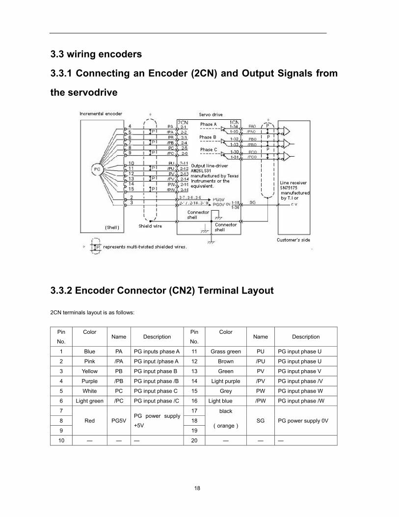
3.3 wiring encoders
3.3.1 Connecting an Encoder (2CN) and Output Signals from
the servodrive
3.3.2 Encoder Connector (CN2) Terminal Layout
2CN terminals layout is as follows:
Pin
No.
Color Name Description
Pin
No.
Color Name Description
1 Blue PA PG inputs phase A 11 Grass green PU PG input phase U
2 Pink /PA PG input /phase A 12 Brown /PU PG input phase U
3 Yellow PB PG input phase B 13 Green PV PG input phase V
4 Purple /PB PG input phase /B 14 Light purple /PV PG input phase /V
5 White PC PG input phase C 15 Grey PW PG input phase W
6 Light green /PC PG input phase /C 16 Light blue /PW PG input phase /W
7
Red PG5V PG power supply
+5V
17 black
(orange) SG PG power supply 0V 8 18
9 19
10 — — — 20 — — —
19
3.4 Wiring servo motor
3.4.1 Encoder Connector Terminal Layout
Pin No. Color Description
1 Red
+5V(power supply)
2 Black (orange) 0V(power supply)
3 Blue A channel output
4 Pink /A channel output
5 Yellow B channel output
6 Purple /B channel output
7 White C channel output
8 Light blue /C channel output
9 Grass blue U channel output
10 Brown /U channel output
11 Green V channel output
12 Light purple /V channel output
13 Grey W channel output
14 Light blue /W channel output
3.4.2 Dynamic power Connector Terminal layout
Pin No. Color Description
1 Blue
FG(Frame grounding)
2 Pink Phase U
3 Yellow Phase V
4 Green Phase W
20
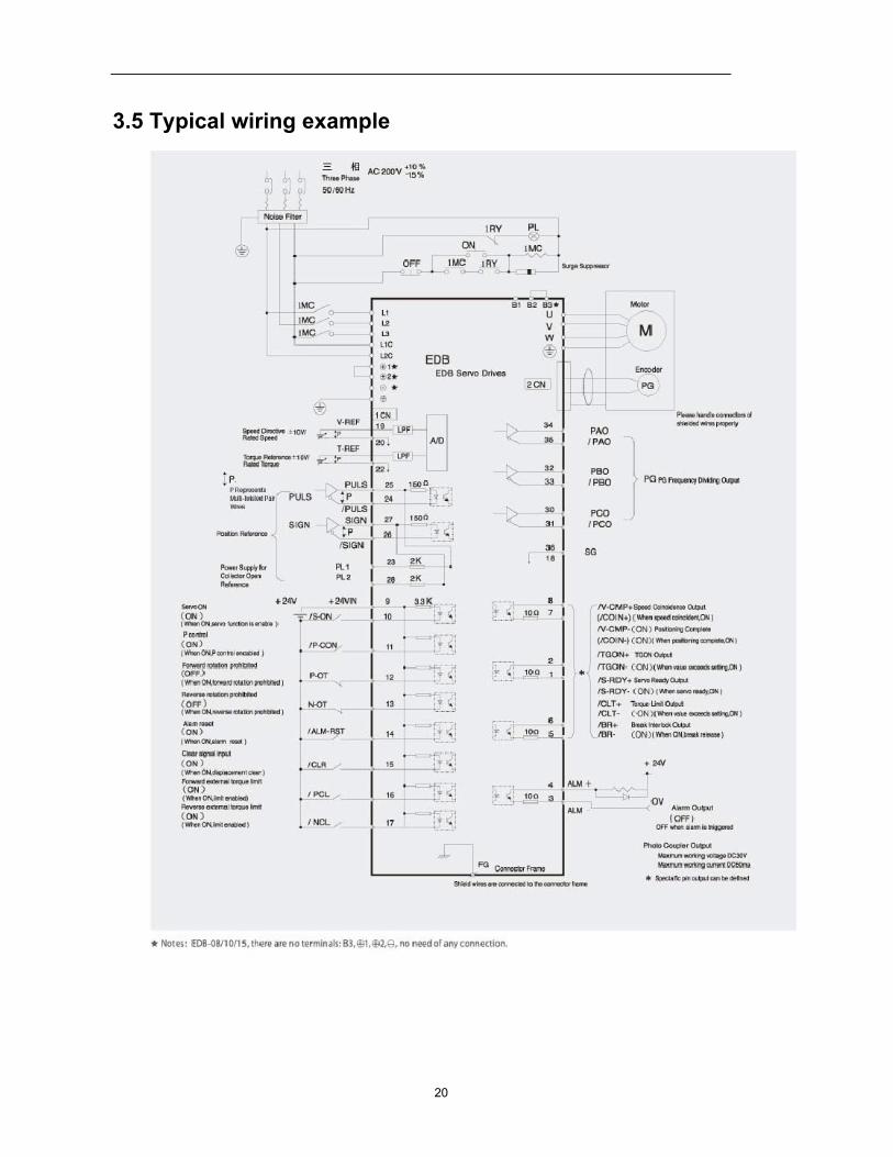
3.5 Typical wiring example
21
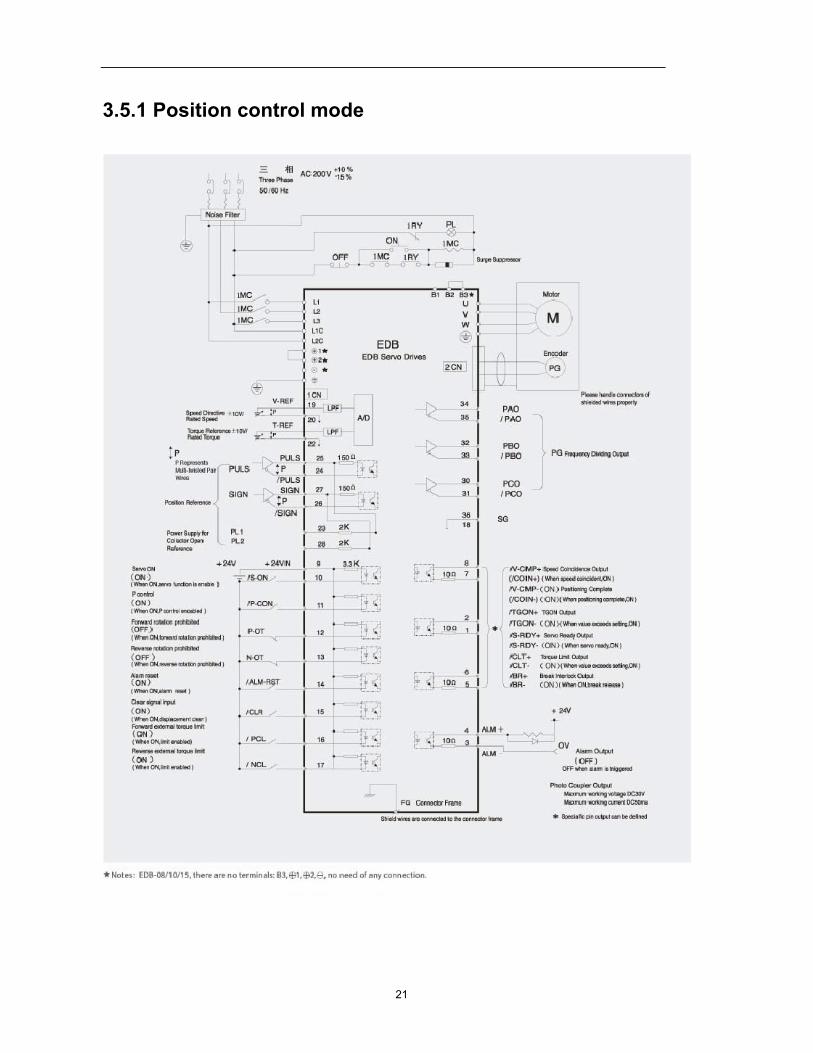
3.5.1 Position control mode

22
3.5.2 Speed control mode
23
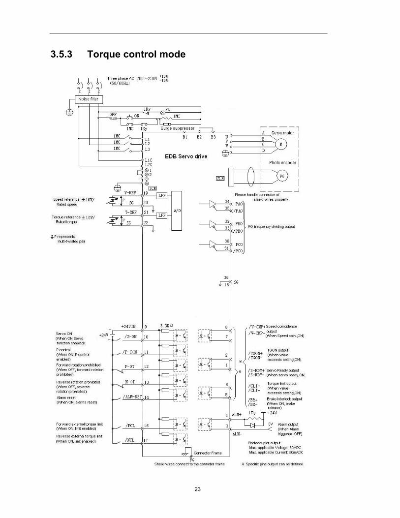
3.5.3 Torque control mode
24
Chapter 4
Parameter Setting and function description
4.1 Setting Parameters according to mechanical features
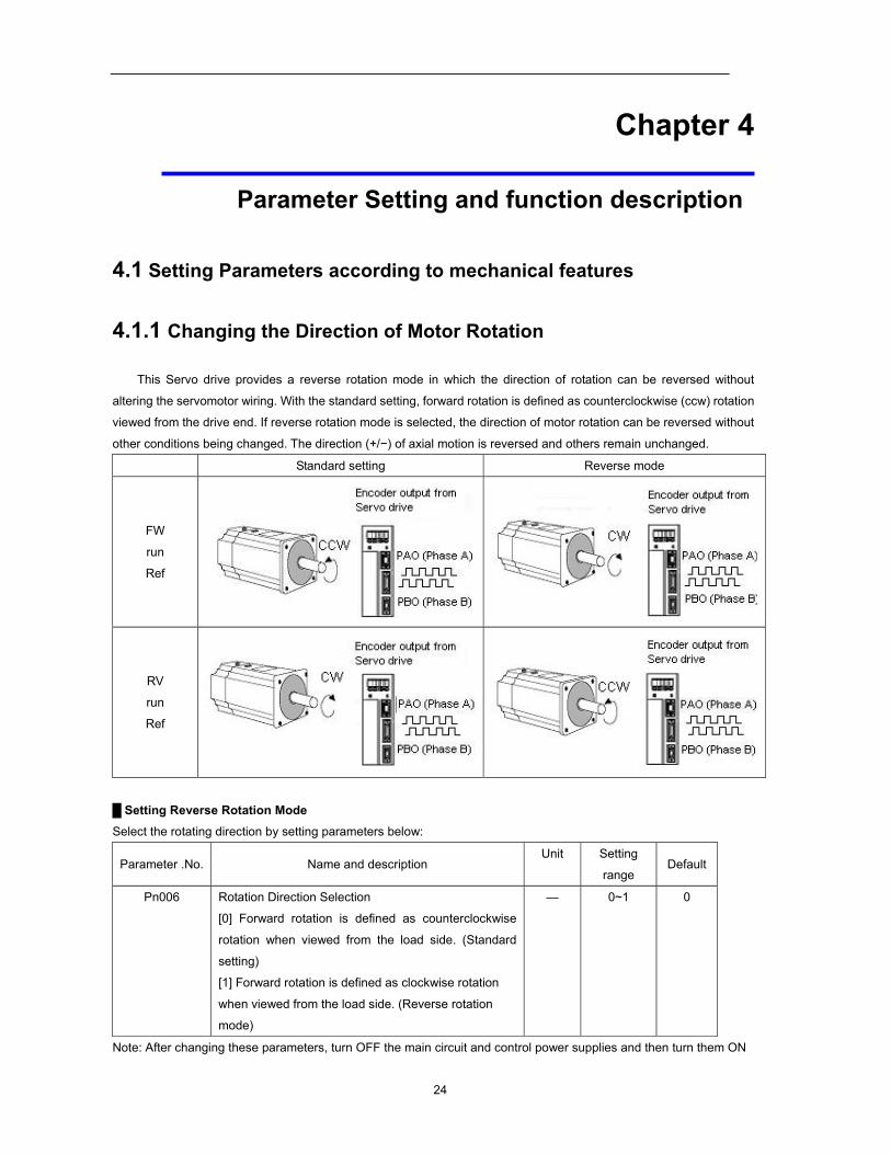
4.1.1 Changing the Direction of Motor Rotation
This Servo drive provides a reverse rotation mode in which the direction of rotation can be reversed without
altering the servomotor wiring. With the standard setting, forward rotation is defined as counterclockwise (ccw) rotation
viewed from the drive end. If reverse rotation mode is selected, the direction of motor rotation can be reversed without
other conditions being changed. The direction (+/−) of axial motion is reversed and others remain unchanged.
Standard setting Reverse mode
FW
run
Ref
RV
run
Ref
Setting Reverse Rotation Mode Select the rotating direction by setting parameters below:
Parameter .No. Name and description Unit Setting
range Default
Pn006 Rotation Direction Selection
[0] Forward rotation is defined as counterclockwise
rotation when viewed from the load side. (Standard
setting)
[1] Forward rotation is defined as clockwise rotation
when viewed from the load side. (Reverse rotation
mode)
— 0~1 0
Note: After changing these parameters, turn OFF the main circuit and control power supplies and then turn them ON
25
again to enable the new settings.
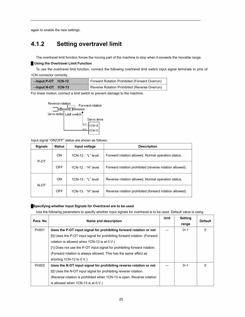
4.1.2 Setting overtravel limit
The overtravel limit function forces the moving part of the machine to stop when it exceeds the movable range.
Using the Overtravel Limit Function
To use the overtravel limit function, connect the following overtravel limit switch input signal terminals to pins of
1CN connector correctly.
→Input P-OT 1CN-12 Forward Rotation Prohibited (Forward Overrun)
→Input N-OT 1CN-13 Reverse Rotation Prohibited (Reverse Overrun)
For linear motion, connect a limit switch to prevent damage to the machine.
Input signal “ON/OFF” status are shown as follows:
Signals Status Input voltage Description
P-OT
ON 1CN-12:“L” level Forward rotation allowed. Normal operation status.
OFF 1CN-12:“H” level Forward rotation prohibited (reverse rotation allowed).
N-OT
ON 1CN-13:“L” level Reverse rotation allowed. Normal operation status.
OFF 1CN-13:“H” level Reverse rotation prohibited (forward rotation allowed).
Specifying whether Input Signals for Overtravel are to be used
Use the following parameters to specify whether input signals for overtravel is to be used. Default value is using.
Para. No Name and description Unit Setting
range Default
Pn001 Uses the P-OT input signal for prohibiting forward rotation or not [0] Uses the P-OT input signal for prohibiting forward rotation. (Forward
rotation is allowed when 1CN-12 is at 0 V.)
[1] Does not use the P-OT input signal for prohibiting forward rotation.
(Forward rotation is always allowed. This has the same effect as
shorting 1CN-12 to 0 V.)
— 0~1 0
Pn002 Uses the N-OT input signal for prohibiting reverse rotation or not [0] Uses the N-OT input signal for prohibiting reverse rotation.
(Reverse rotation is prohibited when 1CN-13 is open. Reverse rotation
is allowed when 1CN-13 is at 0 V.)
— 0~1 0
26
[1] Does not use the N-OT input signal for prohibiting reverse rotation.
(Reverse rotation is always allowed. This has the same effect as
shorting 1CN-13 to 0 V.)
Note: When the servomotor stops due to overtravel during position control, the position error pulses
are held. A clear signal input is required to clear the error pulses.
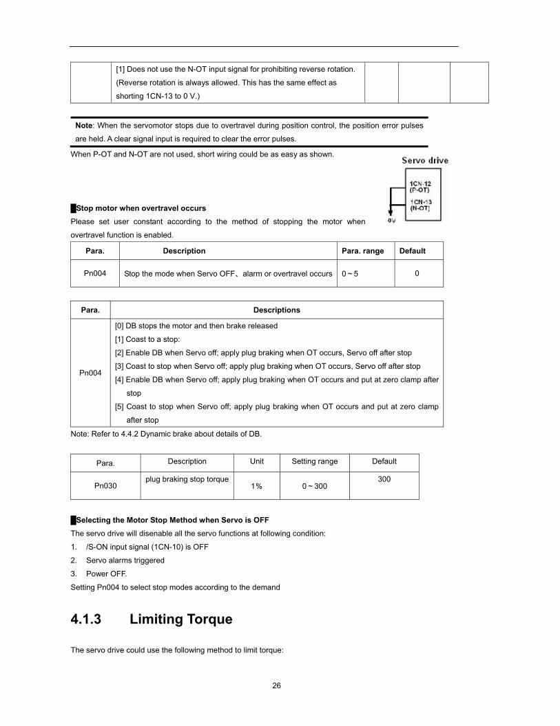
When P-OT and N-OT are not used, short wiring could be as easy as shown.
Stop motor when overtravel occurs
Please set user constant according to the method of stopping the motor when
overtravel function is enabled.
Para. Description Para. range Default
Pn004 Stop the mode when Servo OFF、alarm or overtravel occurs 0~5 0
Para. Descriptions
Pn004
[0] DB stops the motor and then brake released
[1] Coast to a stop:
[2] Enable DB when Servo off; apply plug braking when OT occurs, Servo off after stop
[3] Coast to stop when Servo off; apply plug braking when OT occurs, Servo off after stop
[4] Enable DB when Servo off; apply plug braking when OT occurs and put at zero clamp after
stop
[5] Coast to stop when Servo off; apply plug braking when OT occurs and put at zero clamp
after stop
Note: Refer to 4.4.2 Dynamic brake about details of DB.
Para. Description Unit Setting range Default
Pn030 plug braking stop torque
1% 0~300 300
Selecting the Motor Stop Method when Servo is OFF
The servo drive will disenable all the servo functions at following condition:
1. /S-ON input signal (1CN-10) is OFF
2. Servo alarms triggered
3. Power OFF.
Setting Pn004 to select stop modes according to the demand
4.1.3 Limiting Torque
The servo drive could use the following method to limit torque:
27
Grade 1: Limit the Max output torque to protect press and parts. (Limit internal torque)
Grade 2: Limit torque to move to desired position (limit external torque)
Para. Name and description Unit Setting range Default
Pn026 Forward torque internal limit % 0~300 300
Pn027 Reverse torque internal limit % 0~300 300
Pn028 Forward torque external limit % 0~300 100
Pn029 Reverse torque external limit % 0~300 100
Grade 1 set the internal torque limit Adjust forward and reverse torque limit by setting
parameters (Pn026, Pn027) for limiting torque. After setting the limit,
“/CLT” will output when reach the limit value. If the torque limit is set
higher than the maximum torque of the servomotor, the maximum
torque of the servomotor is used.
Example: for mechanical protection
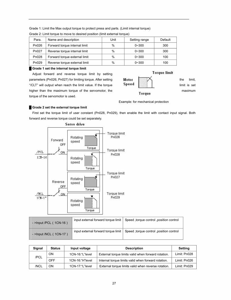
Grade 2 set the external torque limit First set the torque limit of user constant (Pn028, Pn029), then enable the limit with contact input signal. Both
forward and reverse torque could be set separately.
->Input /PCL(1CN-16) input external forward torque limit Speed ,torque control ,position control
->Input /NCL(1CN-17) input external forward torque limit Speed ,torque control ,position control
Signal Status Input voltage Description Setting
/PCL ON 1CN-16:“L”level External torque limits valid when forward rotation. Limit: Pn028
OFF 1CN-16:“H”level Internal torque limits valid when forward rotation. Limit: Pn026
/NCL ON 1CN-17:“L”level External torque limits valid when reverse rotation. Limit: Pn029
28
OFF 1CN-17:“H”level Internal torque limits valid when forward rotation. Limit: Pn027
Set or use torque limit according to external contact input, “/CLT” signal will output if exceeding torque limit. Please
refer to 4.2.10 Torque Limiting Using an Analog Voltage Reference for limiting torque using analog voltage output.
Note:
Do not set the torque limit higher than Max. torque of motor.
Too small a torque limit setting will result in insufficient torque during acceleration and
deceleration.
Note: Please select proper mode for allocating “/PCL, /NCL” signals as torque limit input.
Parameter Name Range Default Application
Pn041 control mode selection 0~13 0 Speed, torque control, position control
“/PCL, /NCL” can’t be allocated as torque limit input in internally set speed control mode.
Pn041 setting Description Possible input signal
0,1,2,7,8,9,
10,11,12,13
Does not use
internal speed
selection
/P-CON(CN1-11) •PI control /P control switch
• switch control mode
• Switch to zero-clamp valid/ invalid
•Switch INHIBIT valid /invalid
•Step changing output
/PCL(CN1-12) • Forward external torque limit output
• looking for reference point
/NCL(CN1-13) • reverse external torque limit output
• looking for reference point
3,4,5,6 Use internal speed
selection
/P-CON /PCL /NCL Speed setting
Direction
selection
0:forward
1:reverse
0 0 Control mode switch
0 1 SPEED1(Pn038)
1 1 SPEED2(Pn039)
1 0 SPEED3(Pn040)
Note: 0: OFF (H level), 1: ON (L level)
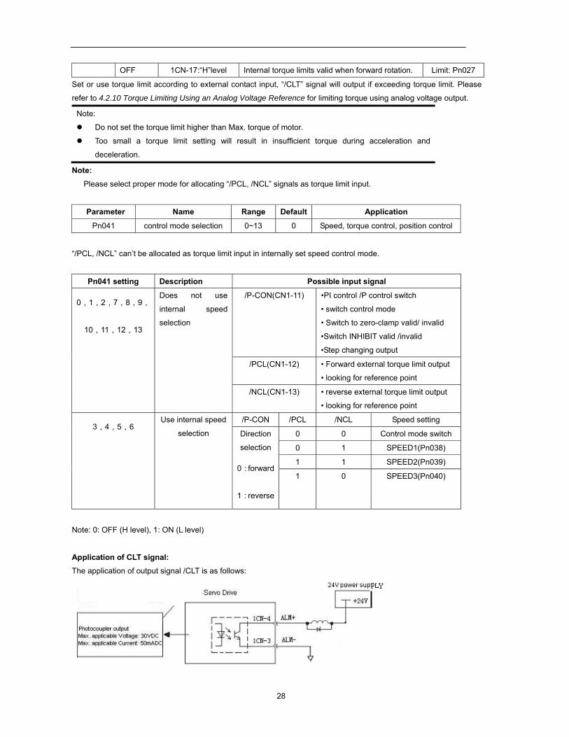
Application of CLT signal: The application of output signal /CLT is as follows:
29
->Output /CLT Torque limit detection output Speed, torque control, position control
Indicates the output torque (current) of motor is limited.
/CLT+ when ON, “L” level Motor output torque under limit
(internal torque reference is higher than setting value )
/CLT+ when OFF “H” level No torque limit
(internal torque reference is lower than setting value )
Please use the following user constants to define output signals and pins when using /CLT signal.
Para. No. Name and description Setting range Default
Pn053 Select output signals 1CN-7,8 functions 0~4 0
Pn054 Select output signals 1CN-1,2 functions 0~4 1
Pn055 Select output signals 1CN-5,6 functions 0~4 2
The pin definitions of Pn053, Pn054 and Pn055 parameter settings are as follows:
0 /COIN(/V-CMP) output
1 /TGON rotation detection output
2 /S-RDY servo ready output
3 /CLT torque limit output
4 BK brake interlock output
4.2 Setting Parameters According to Host Controller
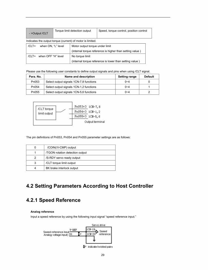
4.2.1 Speed Reference
Analog reference Input a speed reference by using the following input signal “speed reference input.”
30
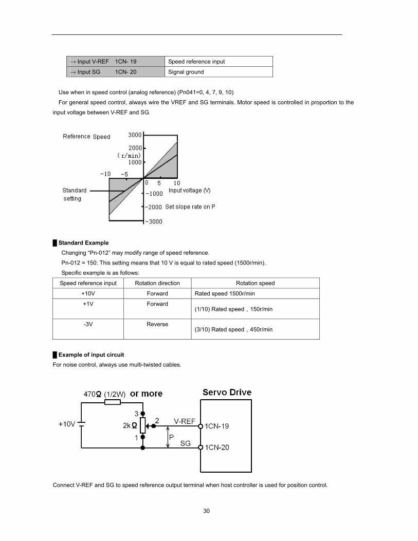
→ Input V-REF 1CN- 19 Speed reference input
→ Input SG 1CN- 20 Signal ground
Use when in speed control (analog reference) (Pn041=0, 4, 7, 9, 10)
For general speed control, always wire the VREF and SG terminals. Motor speed is controlled in proportion to the
input voltage between V-REF and SG.
Standard Example Changing “Pn-012” may modify range of speed reference.
Pn-012 = 150: This setting means that 10 V is equal to rated speed (1500r/min).
Specific example is as follows:
Speed reference input Rotation direction Rotation speed
+10V Forward Rated speed 1500r/min
+1V Forward (1/10) Rated speed,150r/min
-3V Reverse (3/10) Rated speed,450r/min
Example of input circuit For noise control, always use multi-twisted cables.
Connect V-REF and SG to speed reference output terminal when host controller is used for position control.
31
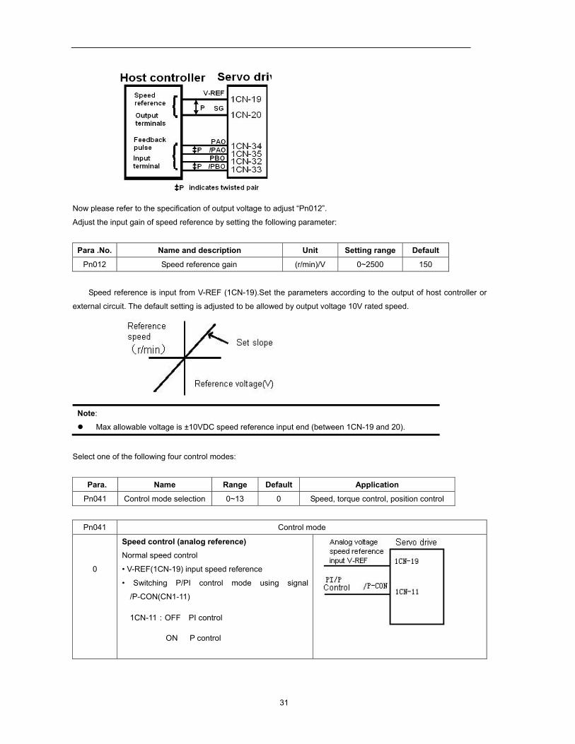
Now please refer to the specification of output voltage to adjust “Pn012”.
Adjust the input gain of speed reference by setting the following parameter:
Para .No. Name and description Unit Setting range Default
Pn012 Speed reference gain (r/min)/V 0~2500 150
Speed reference is input from V-REF (1CN-19).Set the parameters according to the output of host controller or
external circuit. The default setting is adjusted to be allowed by output voltage 10V rated speed.
Note:
Max allowable voltage is ±10VDC speed reference input end (between 1CN-19 and 20).
Select one of the following four control modes:
Para. Name Range Default Application
Pn041 Control mode selection 0~13 0 Speed, torque control, position control
Pn041 Control mode
0
Speed control (analog reference) Normal speed control
• V-REF(1CN-19) input speed reference
• Switching P/PI control mode using signal
/P-CON(CN1-11)
1CN-11:OFF PI control
ON P control
32
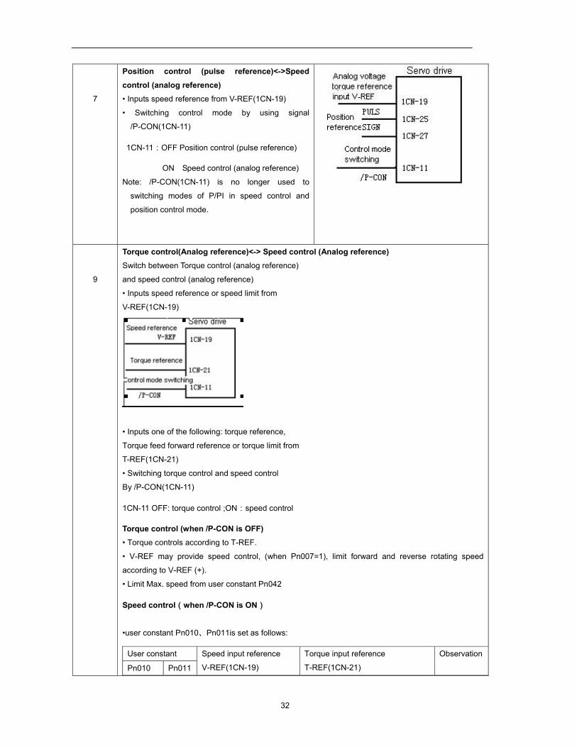
7
Position control (pulse reference)<->Speed control (analog reference) • Inputs speed reference from V-REF(1CN-19)
• Switching control mode by using signal
/P-CON(1CN-11)
1CN-11:OFF Position control (pulse reference)
ON Speed control (analog reference)
Note: /P-CON(1CN-11) is no longer used to
switching modes of P/PI in speed control and
position control mode.
9
Torque control(Analog reference)<-> Speed control (Analog reference) Switch between Torque control (analog reference)
and speed control (analog reference)
• Inputs speed reference or speed limit from
V-REF(1CN-19)
• Inputs one of the following: torque reference,
Torque feed forward reference or torque limit from
T-REF(1CN-21)
• Switching torque control and speed control
By /P-CON(1CN-11)
1CN-11 OFF: torque control ;ON:speed control
Torque control (when /P-CON is OFF) • Torque controls according to T-REF.
• V-REF may provide speed control, (when Pn007=1), limit forward and reverse rotating speed
according to V-REF (+).
• Limit Max. speed from user constant Pn042
Speed control(when /P-CON is ON)
•user constant Pn010、Pn011is set as follows:
User constant Speed input reference
V-REF(1CN-19)
Torque input reference
T-REF(1CN-21)
Observation
Pn010 Pn011
33
0 0 Simple speed control
Speed reference Not used
- 1 speed control with torque feed forward Set Pn010
refer to 4.2.9 Speed reference Torque feed forward
1 0 Torque limit speed control offered by analog voltage reference Refer to
4.2.10
For details Speed reference Torque limit
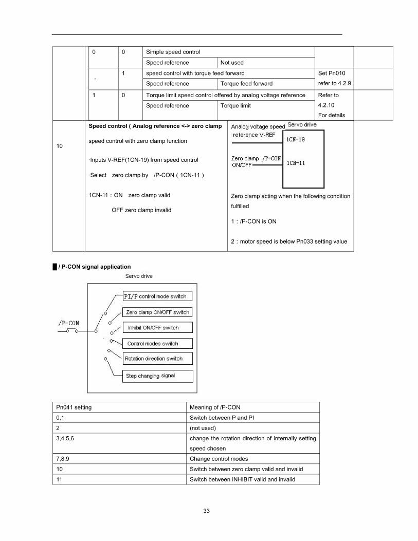
10
Speed control ( Analog reference <-> zero clamp
speed control with zero clamp function
·Inputs V-REF(1CN-19) from speed control
·Select zero clamp by /P-CON(1CN-11)
1CN-11:ON zero clamp valid
OFF zero clamp invalid
Zero clamp acting when the following condition
fulfilled
1:/P-CON is ON
2:motor speed is below Pn033 setting value
/ P-CON signal application
Pn041 setting Meaning of /P-CON
0,1 Switch between P and PI
2 (not used)
3,4,5,6 change the rotation direction of internally setting
speed chosen
7,8,9 Change control modes
10 Switch between zero clamp valid and invalid
11 Switch between INHIBIT valid and invalid
34
12 Step changing signal
13 (not used)
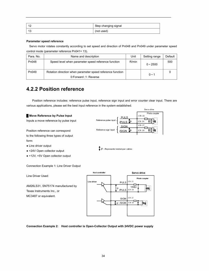
Parameter speed reference Servo motor rotates constantly according to set speed and direction of Pn048 and Pn049 under parameter speed
control mode (parameter reference Pn041= 13).
Para. No. Name and description Unit Setting range Default
Pn048 Speed level when parameter speed reference function R/min 0~2500
500
Pn049 Rotation direction when parameter speed reference function
0:Forward ;1: Reverse
0~1
0
4.2.2 Position reference
Position reference includes: reference pulse input, reference sign input and error counter clear input. There are
various applications, please set the best input reference in the system established.
Move Reference by Pulse Input Inputs a move reference by pulse input
Position reference can correspond
to the following three types of output
form:
Line driver output
+24V Open collector output
+12V, +5V Open collector output
Connection Example 1: Line Driver Output
Line Driver Used:
AM26LS31, SN75174 manufactured by
Texas Instruments Inc., or
MC3487 or equivalent.
Connection Example 2: Host controller is Open-Collector Output with 24VDC power supply
35
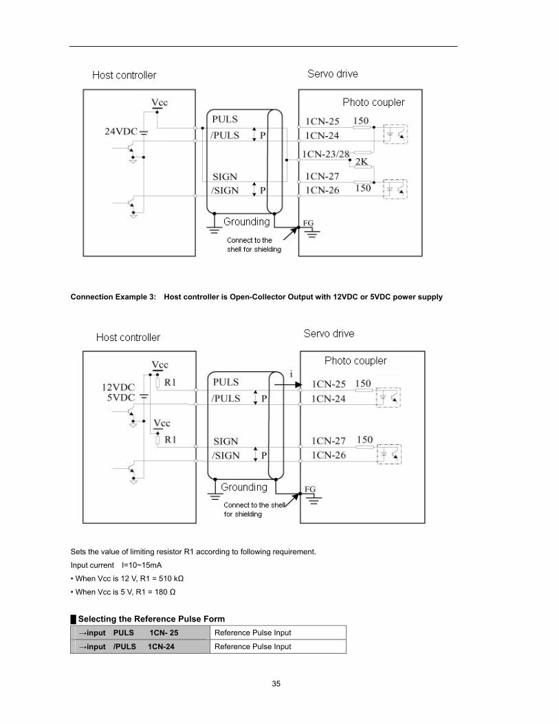
Connection Example 3: Host controller is Open-Collector Output with 12VDC or 5VDC power supply
Sets the value of limiting resistor R1 according to following requirement.
Input current I=10~15mA
• When Vcc is 12 V, R1 = 510 kΩ
• When Vcc is 5 V, R1 = 180 Ω
Selecting the Reference Pulse Form →input PULS 1CN- 25 Reference Pulse Input →input /PULS 1CN-24 Reference Pulse Input
36
→input SIGN 1CN-27 Reference Sign Input →input /SIGN 1CN-26 Reference Sign Input
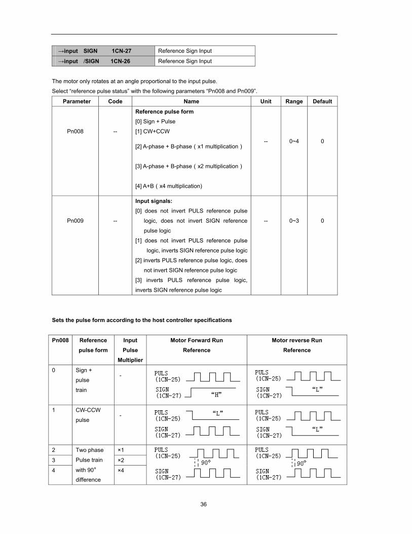
The motor only rotates at an angle proportional to the input pulse.
Select “reference pulse status” with the following parameters “Pn008 and Pn009”.
Parameter Code Name Unit Range Default
Pn008
--
Reference pulse form [0] Sign + Pulse
[1] CW+CCW
[2] A-phase + B-phase(x1 multiplication)
[3] A-phase + B-phase(x2 multiplication)
[4] A+B(x4 multiplication)
--
0~4
0
Pn009
--
Input signals: [0] does not invert PULS reference pulse
logic, does not invert SIGN reference
pulse logic
[1] does not invert PULS reference pulse
logic, inverts SIGN reference pulse logic
[2] inverts PULS reference pulse logic, does
not invert SIGN reference pulse logic
[3] inverts PULS reference pulse logic,
inverts SIGN reference pulse logic
--
0~3
0
Sets the pulse form according to the host controller specifications
Pn008 Reference
pulse form
Input
Pulse Multiplier
Motor Forward Run
Reference
Motor reverse Run
Reference
0 Sign +
pulse
train
-
1 CW-CCW
pulse -
2 Two phase
Pulse train
with 90° difference
×1
3 ×2
4 ×4
37
Select if the
input signal
converted
or not when
setting
parameter
Pn009
according
to your
needs,
Input
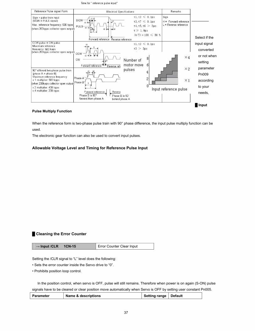
Pulse Multiply Function
When the reference form is two-phase pulse train with 90° phase difference, the input pulse multiply function can be
used.
The electronic gear function can also be used to convert input pulses.
Allowable Voltage Level and Timing for Reference Pulse Input
Cleaning the Error Counter → Input /CLR 1CN-15 Error Counter Clear Input
Setting the /CLR signal to “L” level does the following:
• Sets the error counter inside the Servo drive to “0”.
• Prohibits position loop control.
In the position control, when servo is OFF, pulse will still remains. Therefore when power is on again (S-ON) pulse
signals have to be cleared or clear position move automatically when Servo is OFF by setting user constant Pn005.
Parameter Name & descriptions Setting range Default
38
Pn005 0: S-OFF, clear pulse
1: S-OFF, not clear pulse
0-1 0
Position reference one rank filter wave
Position reference one rank filter wave entitle the improvement of pulse reference form designated by the system,
thus enhance the stability of position control. But if “position reference position one rack filter time constant (Pn024)” set
too high, dynamic function of the system might be decreased.
Parameter Name Unit Setting range Default
Pn024 Position reference
one rank filter wave
time constant
0.1mS 0-32767 0
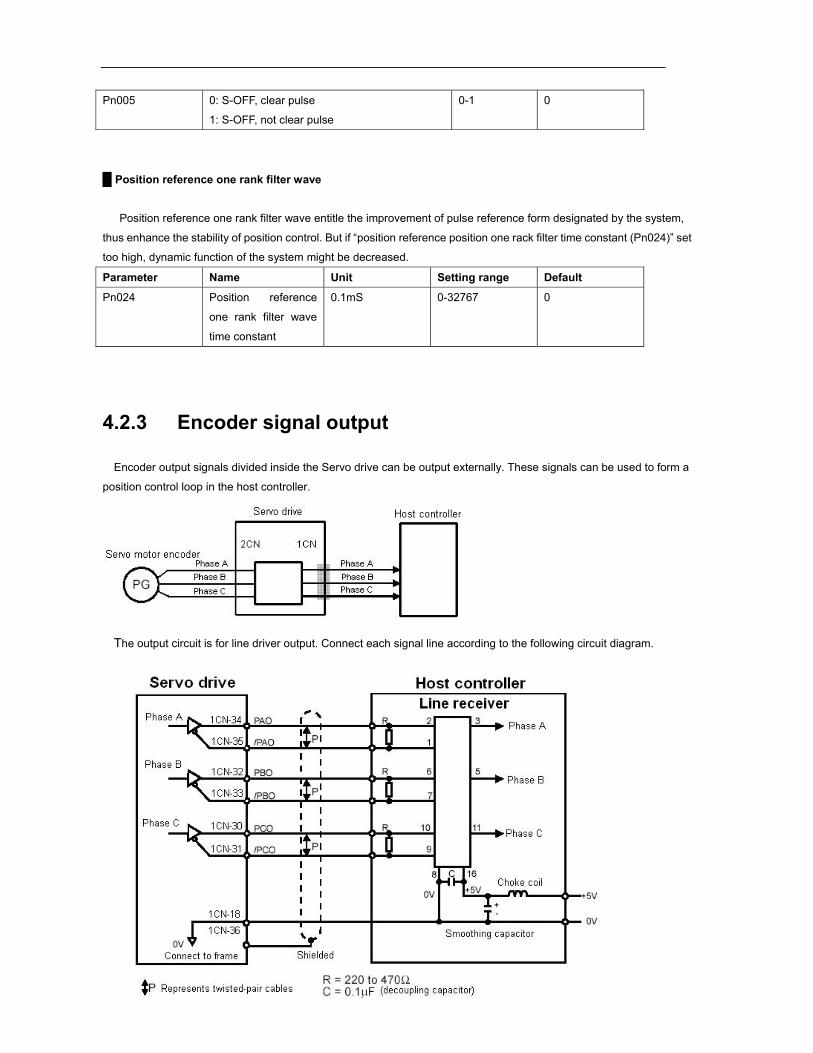
4.2.3 Encoder signal output
Encoder output signals divided inside the Servo drive can be output externally. These signals can be used to form a
position control loop in the host controller.
The output circuit is for line driver output. Connect each signal line according to the following circuit diagram.
39
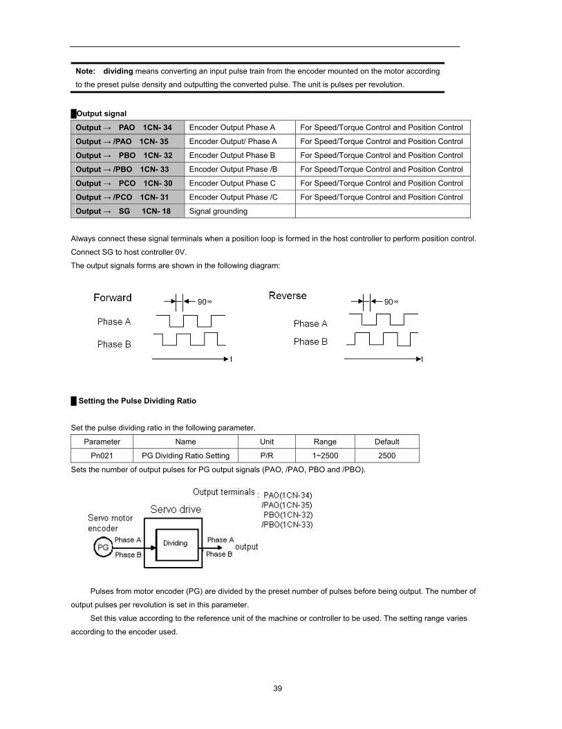
Note: dividing means converting an input pulse train from the encoder mounted on the motor according
to the preset pulse density and outputting the converted pulse. The unit is pulses per revolution.
Output signal
Output → PAO 1CN- 34 Encoder Output Phase A For Speed/Torque Control and Position Control
Output → /PAO 1CN- 35 Encoder Output/ Phase A For Speed/Torque Control and Position Control
Output → PBO 1CN- 32 Encoder Output Phase B For Speed/Torque Control and Position Control
Output → /PBO 1CN- 33 Encoder Output Phase /B For Speed/Torque Control and Position Control
Output → PCO 1CN- 30 Encoder Output Phase C For Speed/Torque Control and Position Control
Output → /PCO 1CN- 31 Encoder Output Phase /C For Speed/Torque Control and Position Control
Output → SG 1CN- 18 Signal grounding
Always connect these signal terminals when a position loop is formed in the host controller to perform position control.
Connect SG to host controller 0V.
The output signals forms are shown in the following diagram:
Setting the Pulse Dividing Ratio
Set the pulse dividing ratio in the following parameter.
Parameter Name Unit Range Default
Pn021 PG Dividing Ratio Setting P/R 1~2500 2500
Sets the number of output pulses for PG output signals (PAO, /PAO, PBO and /PBO).
Pulses from motor encoder (PG) are divided by the preset number of pulses before being output. The number of
output pulses per revolution is set in this parameter.
Set this value according to the reference unit of the machine or controller to be used. The setting range varies
according to the encoder used.

40
Note After changing the parameter setting, always turn the power OFF, then ON.
41
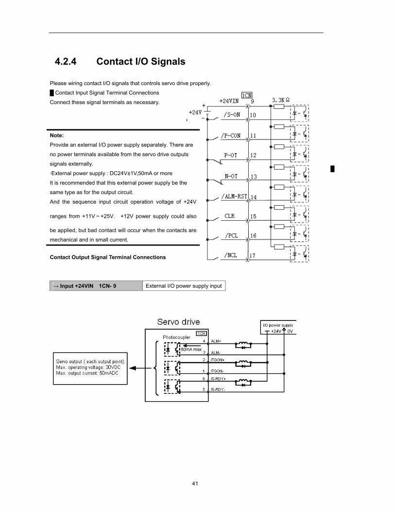
4.2.4 Contact I/O Signals
Please wiring contact I/O signals that controls servo drive properly.
Contact Input Signal Terminal Connections
Connect these signal terminals as necessary.
Contact Output Signal Terminal Connections
→ Input +24VIN 1CN- 9 External I/O power supply input
Note: Provide an external I/O power supply separately. There are
no power terminals available from the servo drive outputs
signals externally.
·External power supply : DC24V±1V,50mA or more
It is recommended that this external power supply be the
same type as for the output circuit.
And the sequence input circuit operation voltage of +24V
ranges from +11V~+25V. +12V power supply could also
be applied, but bad contact will occur when the contacts are
mechanical and in small current.
42
Note : Provide an external I/O power supply separately. There are no power terminals available from the servo
drive outputs signals externally. It is recommended that external power supply be the same type as for the output circuit.
4.2.5 Position control (parameter reference)
Position control under parameter reference (parameter Pn041= 12). In this mode, servo drive could position with a
single axes without host controller.
There are 16 position control points with each could set move distance, running speed, constants for acceleration
and deceleration and the stop time when positioning completed. Two speeds (1. speed moving towards distance
switch “speed of looking for reference point”. 2. Speed moving away from distance switch “moving speed” of reference
points could be set as:
Two position modes: 1. Absolute position mode 2. Relative position mode
Two running modes: 1. Circling mode 2. Non-circling mode
Two step switching method: 1. Delay step switching 2. /P-CON signal switching
Method of looking for reference points: 1. Forward direction 2. Reverse direction
Adjusting offset
Offset of each points has two correspondent parameters: one unit of the parameter is 【x 10000 reference pulse】
and the other is 【x 1 reference pulse】. Setting range of both parameters is: (-9999----+9999), while offset value equals
sum of those two values.
For example:
No.0 offset correspond to parameter Pn059 【x 10000 reference pulse】 and Pn060 【x 1 reference pulse】. Set
Pn059 = 100, Pn060=-100.
No.0 offset value = Pn059x10000 reference pulse + Pn060x1 reference pulse
= 100x10000 reference pulse + (-100)x1 reference pulse
= 999900 reference pulse
With the same principle, we can conclude: in order to get the same results, we also can set Pn059 = 99 and Pn060
= 9900.
Thus, we can see when the two parameters are not zero; we can get same result by two ways: one is to set the two
parameters both negative or both positive, or one negative the other positive.
It is no doubt that setting the parameter could be realized by communication. In computer, corresponding offset
value could be set according to above mentioned method, and one also can set the value directly: choose
“independent position running” in the “operation” menu, then set the value without considering sum of two parameter.
(Refer to PC communication application software------- SP Windows help documents for detailed steps.)
Speed
43
Speed mention here refers to the steady speed during motor running, which is similar to the pulse frequency given
from external in ordinary position control. However, this speed has nothing to do with electronic gear; it is just actual
speed of the motor.
One rank filter time constant
Same as position reference one rank filter time constant Pn024 during ordinary position control (refer to 4.2.2 for
details)
Time for change steps after desired position reached Apply internally delay of changing steps to valid this parameter, that is to set Pn051= 0.
Para. No. Name and description Setting range Default
Pn051
0: delay changing steps, no need of start signal.
1: change steps by /P-CON, no need of start signal
2. delay changing steps, need start signal. (/PCL or /NCL)
3. change steps by /P-CON, need start signal.(/PCL or /NCL)
0~1 0
Time for change steps outputs from positioning completed signal CON/, from Servo ON, or from the time when
reference point is found till Servo perform the program to control position of the point. Such period of time depends on
step changing time required by a point number among start point in program.
For example, the start point of the program Pn219=1, then the step changing time depends on the value of No.0
step changing time Pn187. It could be deduced by analogy when program start points are from 2-15. But when
Pn219=0, then the delay time is No.15 point changing steps time Pn202. During this time and time before when Servo
is OFF, the step display in monitor is the program start point minus one. If Pn219=0, then the “current point “displays in
monitor is “-1”. If Servo OFF after point control program has been performed, then actual step will be displayed in the
monitor. Looking for a new reference point, then the “current step” will display the step before program start point.
When running point control program, if error counter is set as “not clear error counter when Servo OFF”, then the
error counter might flood. If it does not flood, then the servo drive will probably run at the max. running speed when
Servo ON again. PLEASE PAY ATTENTION TO THE SAFETY OF INSTRUMENT.
Para.
No. Name and description
Setting range Default
Pn005 0: clear the error counter when S-OFF
1: not clear the error counter when S-OFF 0~1 0
Looking for the reference point
Looking for the reference point is for establishing a zero physical point of the operating platform, which is used as
zero point in the coordinates during point position control. And users may choose to find a reference point either in
forward side or reverse side.
How to find a reference point Mount a limit switch in the forward or reverse side, find a reference point in the forward direction after connect to
44
/PCL and in the reverse direction after connect to /NCL. When the operating platform bump into the limit switch, motor
will first stop according to the way set by Pn004 and then rotates again against limit switch. When the operating
platform completely departed from limit switch and put motor at the position of first photo encoder Phase C pulse.
Then position of operating platform is set to be zero point of coordinates.
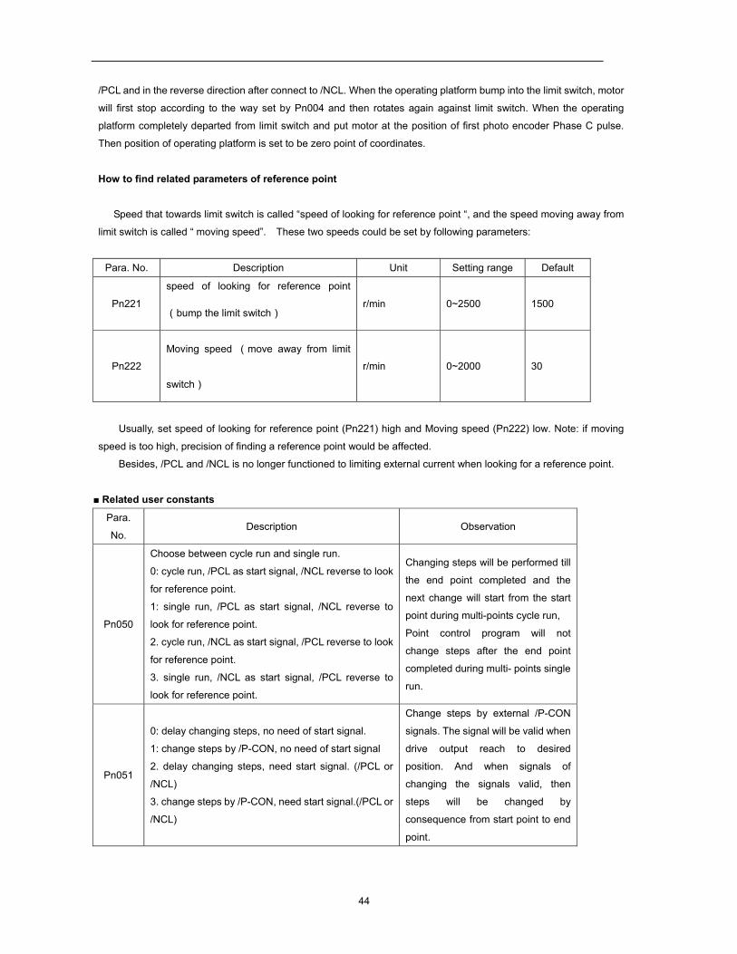
How to find related parameters of reference point
Speed that towards limit switch is called “speed of looking for reference point “, and the speed moving away from
limit switch is called “ moving speed”. These two speeds could be set by following parameters:
Para. No. Description Unit Setting range Default
Pn221
speed of looking for reference point
(bump the limit switch) r/min 0~2500 1500
Pn222
Moving speed (move away from limit
switch)
r/min 0~2000 30
Usually, set speed of looking for reference point (Pn221) high and Moving speed (Pn222) low. Note: if moving
speed is too high, precision of finding a reference point would be affected.
Besides, /PCL and /NCL is no longer functioned to limiting external current when looking for a reference point.
Related user constants
Para.
No. Description Observation
Pn050
Choose between cycle run and single run.
0: cycle run, /PCL as start signal, /NCL reverse to look
for reference point.
1: single run, /PCL as start signal, /NCL reverse to
look for reference point.
2. cycle run, /NCL as start signal, /PCL reverse to look
for reference point.
3. single run, /NCL as start signal, /PCL reverse to
look for reference point.
Changing steps will be performed till
the end point completed and the
next change will start from the start
point during multi-points cycle run,
Point control program will not
change steps after the end point
completed during multi- points single
run.
Pn051
0: delay changing steps, no need of start signal.
1: change steps by /P-CON, no need of start signal
2. delay changing steps, need start signal. (/PCL or
/NCL)
3. change steps by /P-CON, need start signal.(/PCL or
/NCL)
Change steps by external /P-CON
signals. The signal will be valid when
drive output reach to desired
position. And when signals of
changing the signals valid, then
steps will be changed by
consequence from start point to end
point.

45
Pn052 0: incremental
1: absolute
Incremental: relative moving
distance (distance from current
point to next point) programming
Absolute: absolute moving
distance(distance between
operating platform and the
reference point) programming.
46
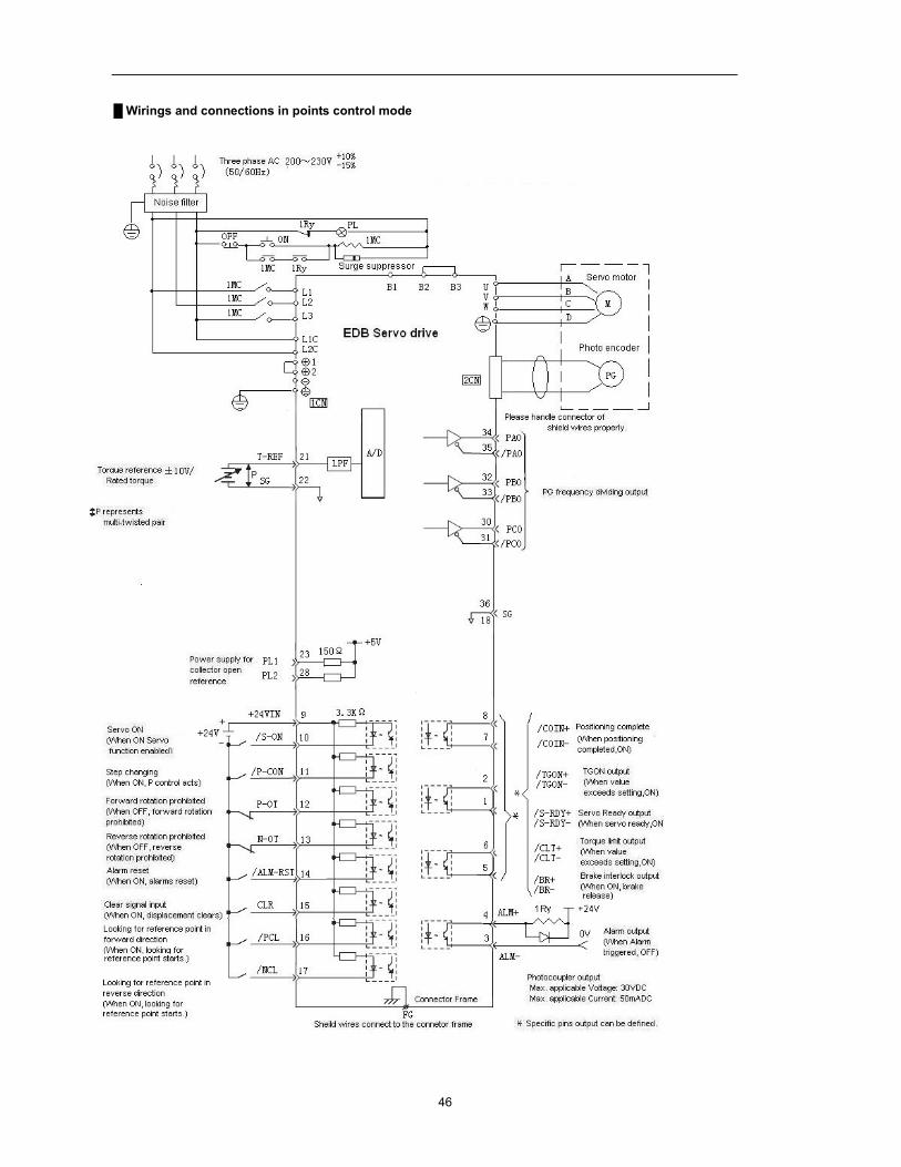
Wirings and connections in points control mode
47
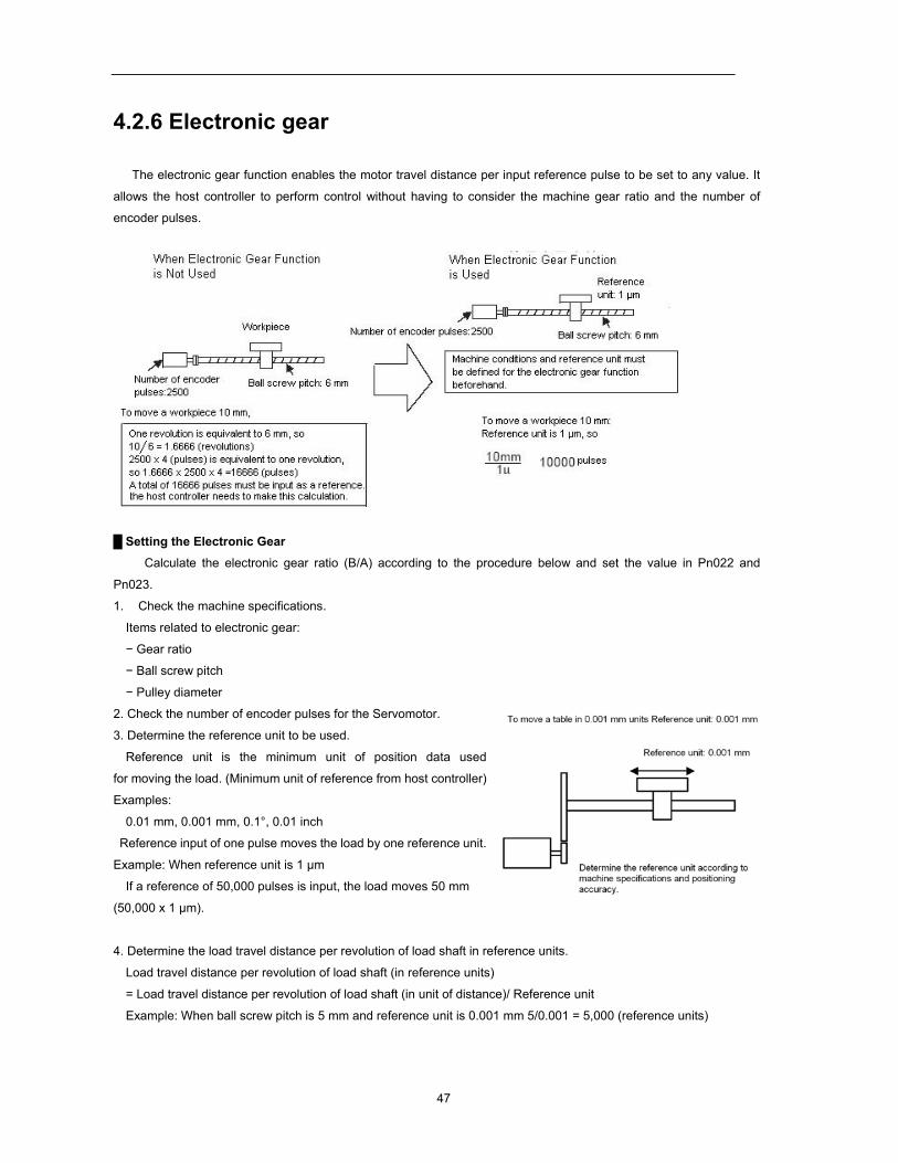
4.2.6 Electronic gear
The electronic gear function enables the motor travel distance per input reference pulse to be set to any value. It
allows the host controller to perform control without having to consider the machine gear ratio and the number of
encoder pulses.
Setting the Electronic Gear
Calculate the electronic gear ratio (B/A) according to the procedure below and set the value in Pn022 and
Pn023.
1. Check the machine specifications.
Items related to electronic gear:
− Gear ratio
− Ball screw pitch
− Pulley diameter
2. Check the number of encoder pulses for the Servomotor.
3. Determine the reference unit to be used.
Reference unit is the minimum unit of position data used
for moving the load. (Minimum unit of reference from host controller)
Examples:
0.01 mm, 0.001 mm, 0.1°, 0.01 inch
Reference input of one pulse moves the load by one reference unit.
Example: When reference unit is 1 μm
If a reference of 50,000 pulses is input, the load moves 50 mm
(50,000 x 1 μm).
4. Determine the load travel distance per revolution of load shaft in reference units.
Load travel distance per revolution of load shaft (in reference units)
= Load travel distance per revolution of load shaft (in unit of distance)/ Reference unit
Example: When ball screw pitch is 5 mm and reference unit is 0.001 mm 5/0.001 = 5,000 (reference units)
48
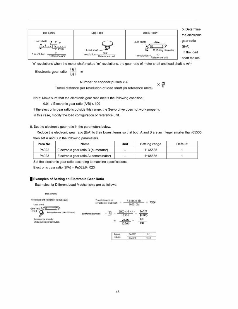
5. Determine
the electronic
gear ratio
(B/A)
If the load
shaft makes
“n” revolutions when the motor shaft makes “m” revolutions, the gear ratio of motor shaft and load shaft is m/n
Note: Make sure that the electronic gear ratio meets the following condition:
0.01 ≤ Electronic gear ratio (A/B) ≤ 100
If the electronic gear ratio is outside this range, the Servo drive does not work properly.
In this case, modify the load configuration or reference unit.
6. Set the electronic gear ratio in the parameters below.
Reduce the electronic gear ratio (B/A) to their lowest terms so that both A and B are an integer smaller than 65535,
then set A and B in the following parameters.
Para.No. Name Unit Setting range Default
Pn022 Electronic gear ratio B (numerator) -- 1~65535 1
Pn023 Electronic gear ratio A (denominator) -- 1~65535 1
Set the electronic gear ratio according to machine specifications.
Electronic gear ratio (B/A) = Pn022/Pn023
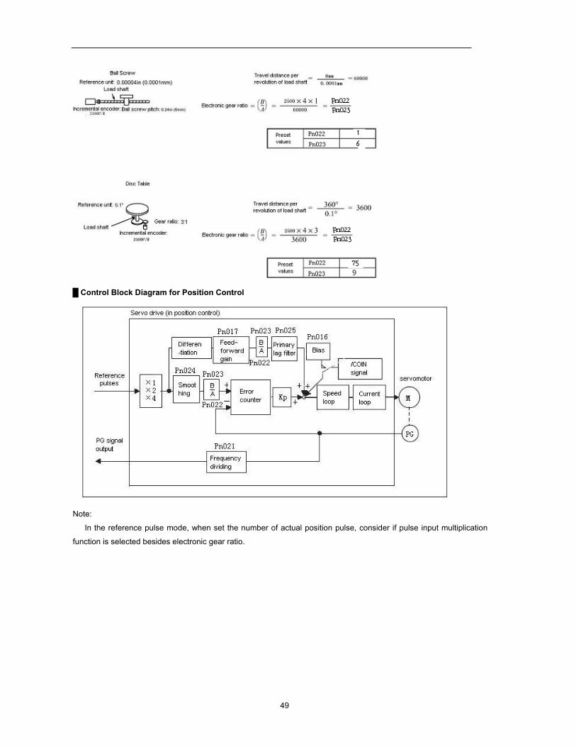
Examples of Setting an Electronic Gear Ratio Examples for Different Load Mechanisms are as follows:
49
Control Block Diagram for Position Control
Note:
In the reference pulse mode, when set the number of actual position pulse, consider if pulse input multiplication
function is selected besides electronic gear ratio.
50
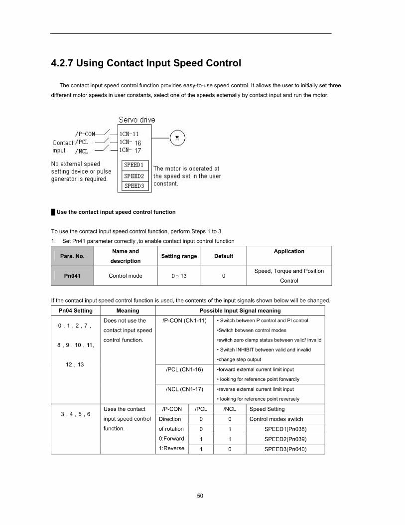
4.2.7 Using Contact Input Speed Control
The contact input speed control function provides easy-to-use speed control. It allows the user to initially set three
different motor speeds in user constants, select one of the speeds externally by contact input and run the motor.
Use the contact input speed control function To use the contact input speed control function, perform Steps 1 to 3
1. Set Pn41 parameter correctly ,to enable contact input control function
Para. No. Name and
description Setting range Default
Application
Pn041 Control mode 0~13 0 Speed, Torque and Position
Control
If the contact input speed control function is used, the contents of the input signals shown below will be changed.
Pn04 Setting Meaning Possible Input Signal meaning
0,1,2,7,
8,9,10,11,
12,13
Does not use the contact input speed
control function.
/P-CON (CN1-11) • Switch between P control and PI control.
•Switch between control modes
•switch zero clamp status between valid/ invalid
• Switch INHIBIT between valid and invalid
•change step output
/PCL (CN1-16) •forward external current limit input
• looking for reference point forwardly
/NCL (CN1-17) •reverse external current limit input • looking for reference point reversely
3,4,5,6 Uses the contact
input speed control
function.
/P-CON /PCL /NCL Speed Setting
Direction
of rotation
0:Forward
1:Reverse
0 0 Control modes switch
0 1 SPEED1(Pn038)
1 1 SPEED2(Pn039)
1 0 SPEED3(Pn040)
51
2. Set three motor speeds in the following user constants.
Pn038 SPEED1
1st Speed (Contact
Input Speed Control)
Unit: r/min
Setting Range:
0~2500
Default:
100
Speed control
Pn039 SPEED2
2nd Speed (Contact
Input Speed Control)
Unit: r/min
Setting
Range:
0~2500
Default:
200
Speed control
Pn040 SPEED3
3rd Speed (Contact
Input Speed Control)
Unit: r/min
Setting
Range:
0~2500
Default:
300
Speed control
Use these parameters to set motor speeds when the contact input speed control function is used. If a value higher
than the maximum speed is set, the maximum speed value is used.
Speed selection input signals /PCL (1CN-16) and /NCL (1CN-17), and rotation direction selection signal /P-CON
(1CN-11) enable the motor to run at the preset speeds.
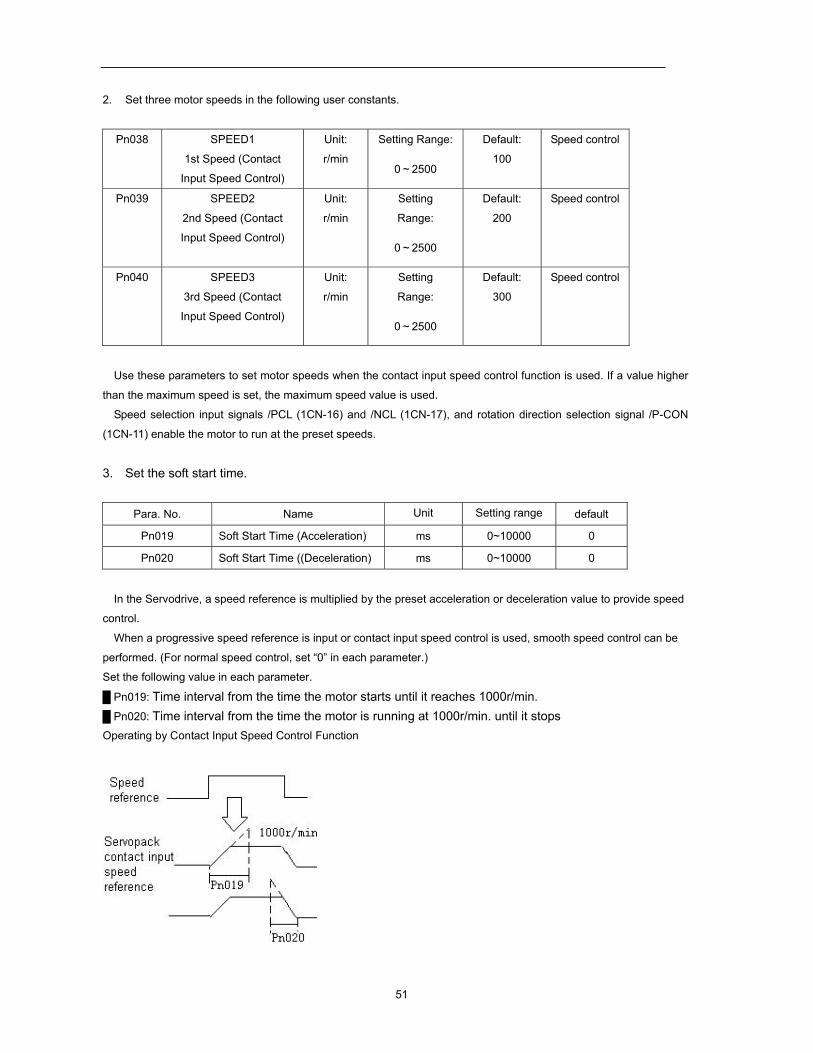
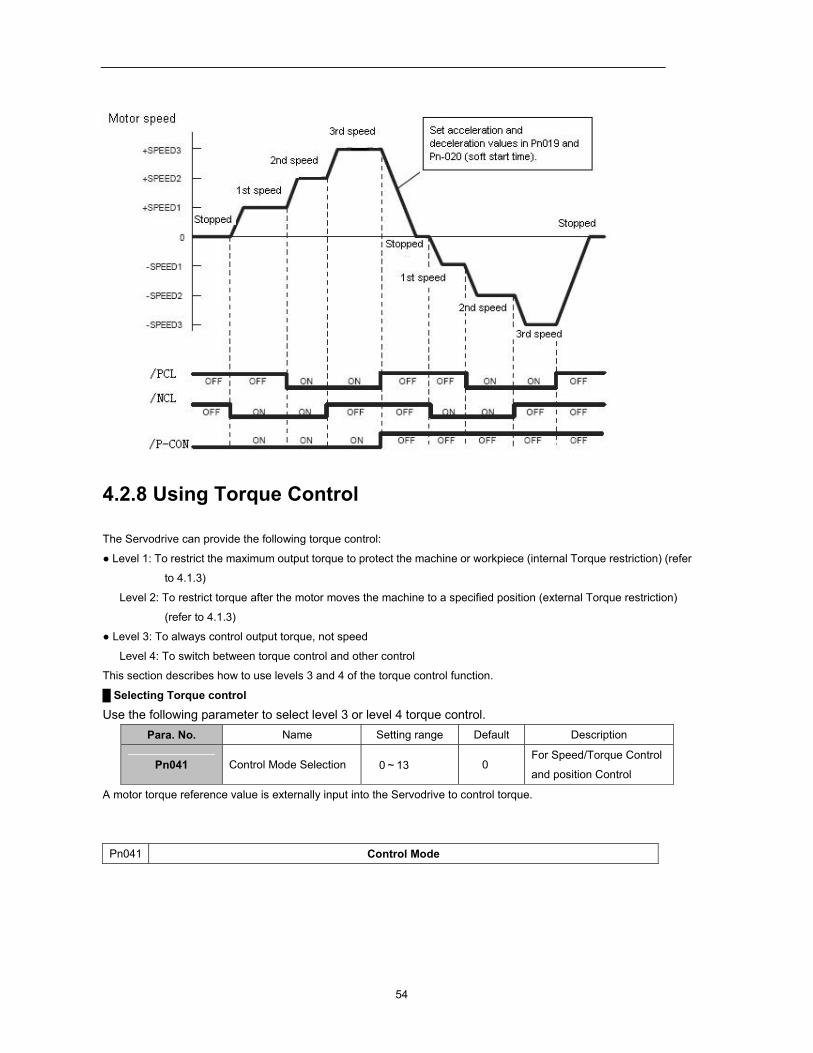
3. Set the soft start time.
Para. No. Name Unit Setting range default
Pn019 Soft Start Time (Acceleration) ms 0~10000 0
Pn020 Soft Start Time ((Deceleration) ms 0~10000 0
In the Servodrive, a speed reference is multiplied by the preset acceleration or deceleration value to provide speed
control.
When a progressive speed reference is input or contact input speed control is used, smooth speed control can be
performed. (For normal speed control, set “0” in each parameter.)
Set the following value in each parameter.
Pn019: Time interval from the time the motor starts until it reaches 1000r/min. Pn020: Time interval from the time the motor is running at 1000r/min. until it stops Operating by Contact Input Speed Control Function
52
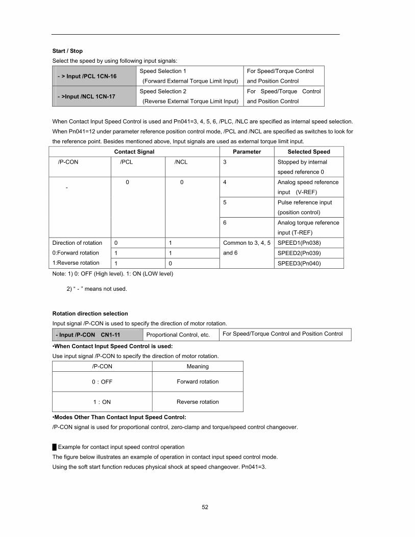
Start / Stop Select the speed by using following input signals:
-> Input /PCL 1CN-16 Speed Selection 1
(Forward External Torque Limit Input)
For Speed/Torque Control
and Position Control
->Input /NCL 1CN-17 Speed Selection 2
(Reverse External Torque Limit Input)
For Speed/Torque Control
and Position Control
When Contact Input Speed Control is used and Pn041=3, 4, 5, 6, /PLC, /NLC are specified as internal speed selection.
When Pn041=12 under parameter reference position control mode, /PCL and /NCL are specified as switches to look for
the reference point. Besides mentioned above, Input signals are used as external torque limit input.
Contact Signal Parameter Selected Speed /P-CON /PCL /NCL 3 Stopped by internal
speed reference 0
- 0 0 4 Analog speed reference
input (V-REF)
5 Pulse reference input
(position control)
6 Analog torque reference
input (T-REF)
Direction of rotation 0:Forward rotation
1:Reverse rotation
0 1 Common to 3, 4, 5
and 6
SPEED1(Pn038)
1 1 SPEED2(Pn039)
1 0 SPEED3(Pn040)
Note: 1) 0: OFF (High level). 1: ON (LOW level)
2) “-” means not used.
Rotation direction selection Input signal /P-CON is used to specify the direction of motor rotation.
- Input /P-CON CN1-11 Proportional Control, etc. For Speed/Torque Control and Position Control
•When Contact Input Speed Control is used: Use input signal /P-CON to specify the direction of motor rotation.
/P-CON Meaning
0:OFF Forward rotation
1:ON Reverse rotation
•Modes Other Than Contact Input Speed Control: /P-CON signal is used for proportional control, zero-clamp and torque/speed control changeover.
Example for contact input speed control operation
The figure below illustrates an example of operation in contact input speed control mode.
Using the soft start function reduces physical shock at speed changeover. Pn041=3.

53
54
4.2.8 Using Torque Control
The Servodrive can provide the following torque control:
Level 1: To restrict the maximum output torque to protect the machine or workpiece (internal Torque restriction) (refer
to 4.1.3)
Level 2: To restrict torque after the motor moves the machine to a specified position (external Torque restriction)
(refer to 4.1.3)
Level 3: To always control output torque, not speed
Level 4: To switch between torque control and other control
This section describes how to use levels 3 and 4 of the torque control function.
Selecting Torque control
Use the following parameter to select level 3 or level 4 torque control. Para. No. Name Setting range Default Description
Pn041 Control Mode Selection 0~13 0 For Speed/Torque Control
and position Control
A motor torque reference value is externally input into the Servodrive to control torque.
Pn041 Control Mode
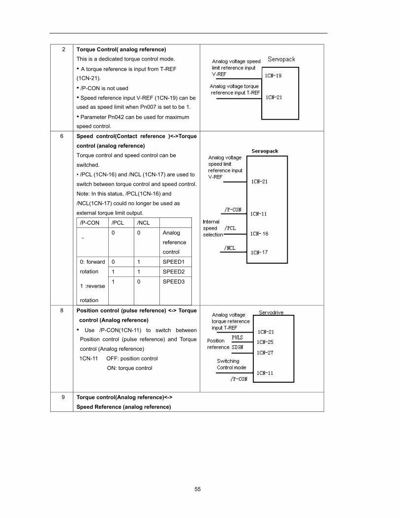
55
2 Torque Control( analog reference) This is a dedicated torque control mode. • A torque reference is input from T-REF (1CN-21).
• /P-CON is not used
• Speed reference input V-REF (1CN-19) can be used as speed limit when Pn007 is set to be 1. • Parameter Pn042 can be used for maximum speed control.
6 Speed control(Contact reference )<->Torque control (analog reference) Torque control and speed control can be
switched.
• /PCL (1CN-16) and /NCL (1CN-17) are used to
switch between torque control and speed control.
Note: In this status, /PCL(1CN-16) and
/NCL(1CN-17) could no longer be used as
external torque limit output.
/P-CON /PCL /NCL
- 0 0 Analog
reference
control
0: forward
rotation
1:reverse
rotation
0 1 SPEED1
1 1 SPEED2
1 0 SPEED3
8 Position control (pulse reference) <-> Torque
control (Analog reference)
• Use /P-CON(1CN-11) to switch between Position control (pulse reference) and Torque
control (Analog reference)
1CN-11 OFF: position control
ON: torque control
9 Torque control(Analog reference)<->
Speed Reference (analog reference)
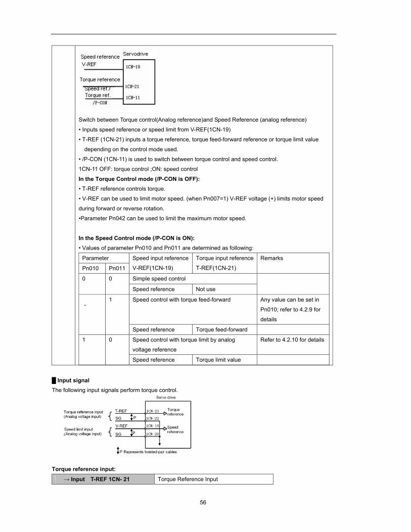
56
Switch between Torque control(Analog reference)and Speed Reference (analog reference)
• Inputs speed reference or speed limit from V-REF(1CN-19)
• T-REF (1CN-21) inputs a torque reference, torque feed-forward reference or torque limit value
depending on the control mode used.
• /P-CON (1CN-11) is used to switch between torque control and speed control.
1CN-11 OFF: torque control ;ON: speed control
In the Torque Control mode (/P-CON is OFF): • T-REF reference controls torque. • V-REF can be used to limit motor speed. (when Pn007=1) V-REF voltage (+) limits motor speed
during forward or reverse rotation.
•Parameter Pn042 can be used to limit the maximum motor speed.
In the Speed Control mode (/P-CON is ON): • Values of parameter Pn010 and Pn011 are determined as following:
Parameter Speed input reference
V-REF(1CN-19)
Torque input reference
T-REF(1CN-21)
Remarks
Pn010 Pn011
0 0 Simple speed control
Speed reference Not use
- 1 Speed control with torque feed-forward Any value can be set in
Pn010; refer to 4.2.9 for
details
Speed reference Torque feed-forward
1 0 Speed control with torque limit by analog
voltage reference
Refer to 4.2.10 for details
Speed reference Torque limit value
Input signal The following input signals perform torque control.
Torque reference input:
→ Input T-REF 1CN- 21 Torque Reference Input
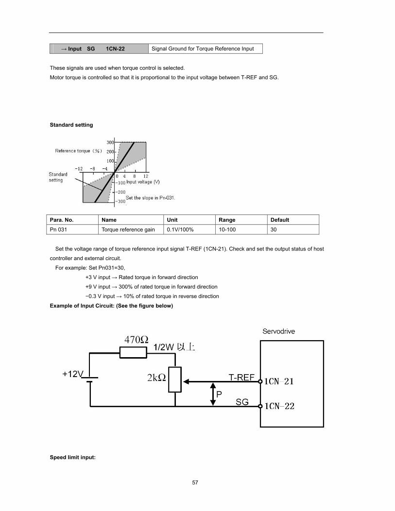
57
→ Input SG 1CN-22 Signal Ground for Torque Reference Input
These signals are used when torque control is selected.
Motor torque is controlled so that it is proportional to the input voltage between T-REF and SG.
Standard setting
Para. No. Name Unit Range Default
Pn 031 Torque reference gain 0.1V/100% 10-100 30
Set the voltage range of torque reference input signal T-REF (1CN-21). Check and set the output status of host
controller and external circuit.
For example: Set Pn031=30,
+3 V input → Rated torque in forward direction
+9 V input → 300% of rated torque in forward direction
−0.3 V input → 10% of rated torque in reverse direction
Example of Input Circuit: (See the figure below)
Speed limit input:
58
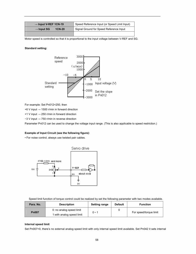
→ Input V-REF 1CN-19 Speed Reference Input (or Speed Limit Input)
→ Input SG 1CN-20 Signal Ground for Speed Reference Input
Motor speed is controlled so that it is proportional to the input voltage between V-REF and SG.
Standard setting:
For example: Set Pn012=250, then
+6 V input → 1500 r/min in forward direction
+1 V input → 250 r/min in forward direction
−3 V input → 750 r/min in reverse direction
Parameter Pn012 can be used to change the voltage input range. (This is also applicable to speed restriction.)
Example of Input Circuit (see the following figure): • For noise control, always use twisted pair cables.
Speed limit function of torque control could be realized by set the following parameter with two modes available.
Para. No. Description Setting range Default Function
Pn007 0: no analog speed limit
1:with analog speed limit 0~1
0 For speed/torque limit
Internal speed limit Set Pn007=0, there’s no external analog speed limit with only internal speed limit available. Set Pn042 it sets internal
59
limit value of motor speed in torque control mode.
Para. No. Description Unit Setting
range Default Function
Pn042 Speed limit in torque
control mode r/min 1-2500 2500 For speed/torque control
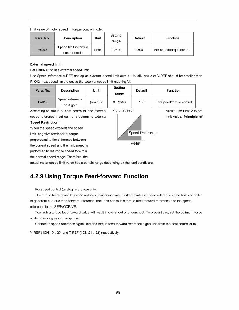
External speed limit Set Pn007=1 to use external speed limit
Use Speed reference V-REF analog as external speed limit output. Usually, value of V-REF should be smaller than
Pn042 max. speed limit to entitle the external speed limit meaningful.
Para. No. Description Unit Setting
range Default Function
Pn012 Speed reference
input gain (r/min)/V 0~2500 150 For Speed/torque control
According to status of host controller and external circuit, use Pn012 to set
speed reference input gain and determine external limit value. Principle of
Speed Restriction: When the speed exceeds the speed
limit, negative feedback of torque
proportional to the difference between
the current speed and the limit speed is
performed to return the speed to within
the normal speed range. Therefore, the
actual motor speed limit value has a certain range depending on the load conditions.
4.2.9 Using Torque Feed-forward Function
For speed control (analog reference) only.
The torque feed-forward function reduces positioning time. It differentiates a speed reference at the host controller
to generate a torque feed-forward reference, and then sends this torque feed-forward reference and the speed
reference to the SERVODRIVE.
Too high a torque feed-forward value will result in overshoot or undershoot. To prevent this, set the optimum value
while observing system response.
Connect a speed reference signal line and torque feed-forward reference signal line from the host controller to
V-REF (1CN-19,20) and T-REF (1CN-21,22) respectively.
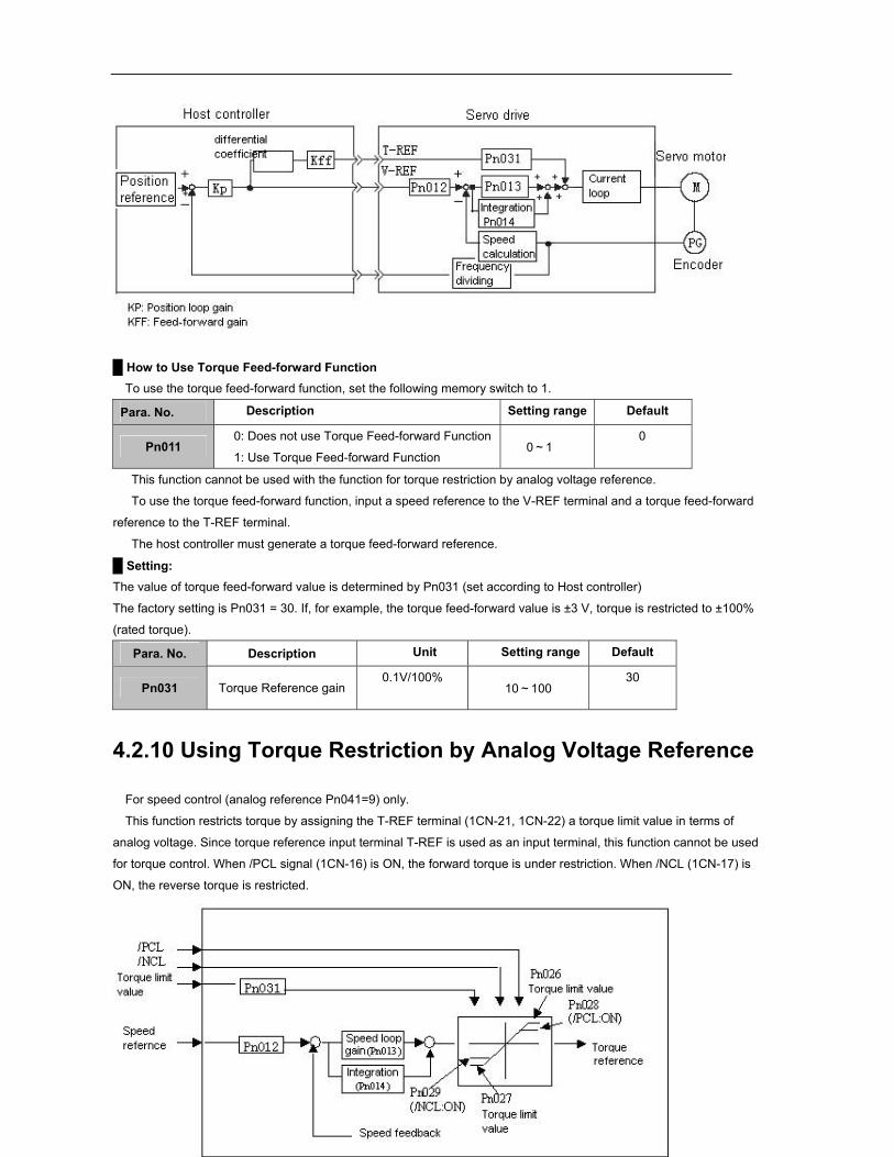
60
How to Use Torque Feed-forward Function
To use the torque feed-forward function, set the following memory switch to 1.
Para. No. Description Setting range Default
Pn011 0: Does not use Torque Feed-forward Function
1: Use Torque Feed-forward Function 0~1
0
This function cannot be used with the function for torque restriction by analog voltage reference.
To use the torque feed-forward function, input a speed reference to the V-REF terminal and a torque feed-forward
reference to the T-REF terminal.
The host controller must generate a torque feed-forward reference.
Setting: The value of torque feed-forward value is determined by Pn031 (set according to Host controller)
The factory setting is Pn031 = 30. If, for example, the torque feed-forward value is ±3 V, torque is restricted to ±100%
(rated torque).
Para. No. Description Unit Setting range Default
Pn031 Torque Reference gain 0.1V/100%
10~100 30
4.2.10 Using Torque Restriction by Analog Voltage Reference
For speed control (analog reference Pn041=9) only.
This function restricts torque by assigning the T-REF terminal (1CN-21, 1CN-22) a torque limit value in terms of
analog voltage. Since torque reference input terminal T-REF is used as an input terminal, this function cannot be used
for torque control. When /PCL signal (1CN-16) is ON, the forward torque is under restriction. When /NCL (1CN-17) is
ON, the reverse torque is restricted.
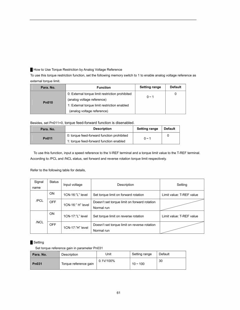
61
How to Use Torque Restriction by Analog Voltage Reference
To use this torque restriction function, set the following memory switch to 1 to enable analog voltage reference as
external torque limit.
Para. No. Function Setting range Default
Pn010
0: External torque limit restriction prohibited
(analog voltage reference) 1: External torque limit restriction enabled
(analog voltage reference)
0~1 0
Besides, set Pn011=0, torque feed-forward function is disenabled.
Para. No. Description Setting range Default
Pn011 0: torque feed-forward function prohibited
1: torque feed-forward function enabled 0~1
0
To use this function, input a speed reference to the V-REF terminal and a torque limit value to the T-REF terminal.
According to /PCL and /NCL status, set forward and reverse rotation torque limit respectively.
Refer to the following table for details,
Signal
name
Status Input voltage Description Setting
/PCL
ON 1CN-16:”L” level Set torque limit on forward rotation Limit value: T-REF value
OFF 1CN-16:” H” level
Doesn’t set torque limit on forward rotation
Normal run
/NCL
ON 1CN-17:”L” level Set torque limit on reverse rotation Limit value: T-REF value
OFF 1CN-17:”H” level
Doesn’t set torque limit on reverse rotation
Normal run
Setting
Set torque reference gain in parameter Pn031
Para. No. Description Unit Setting range Default
Pn031 Torque reference gain 0.1V/100%
10~100 30
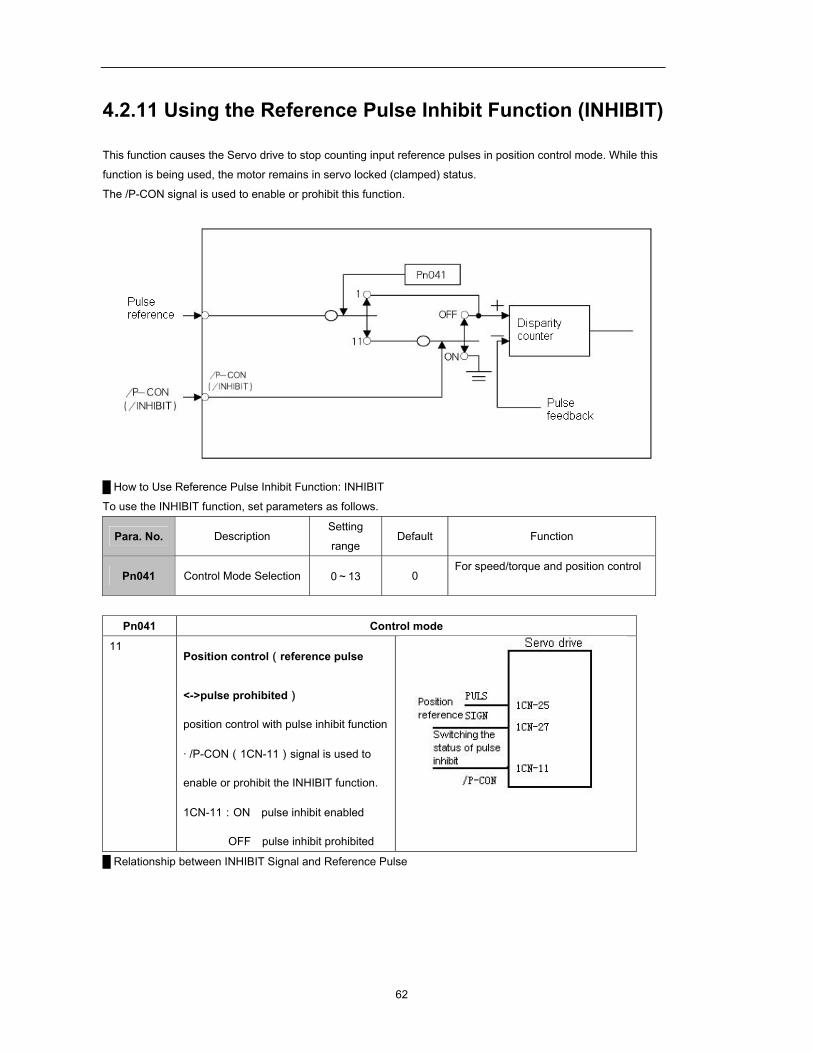
62
4.2.11 Using the Reference Pulse Inhibit Function (INHIBIT)
This function causes the Servo drive to stop counting input reference pulses in position control mode. While this
function is being used, the motor remains in servo locked (clamped) status.
The /P-CON signal is used to enable or prohibit this function.
How to Use Reference Pulse Inhibit Function: INHIBIT
To use the INHIBIT function, set parameters as follows.
Para. No. Description Setting
range Default Function
Pn041 Control Mode Selection 0~13 0 For speed/torque and position control
Pn041 Control mode
11 Position control(reference pulse
<->pulse prohibited)
position control with pulse inhibit function
· /P-CON(1CN-11)signal is used to
enable or prohibit the INHIBIT function.
1CN-11:ON pulse inhibit enabled
OFF pulse inhibit prohibited
Relationship between INHIBIT Signal and Reference Pulse
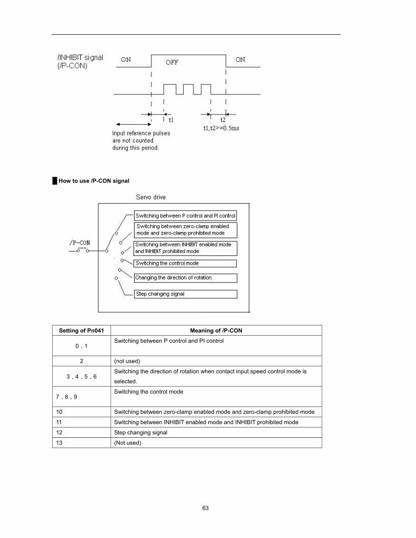
63
How to use /P-CON signal
Setting of Pn041 Meaning of /P-CON
0,1 Switching between P control and PI control
2 (not used)
3,4,5,6 Switching the direction of rotation when contact input speed control mode is
selected.
7,8,9 Switching the control mode
10 Switching between zero-clamp enabled mode and zero-clamp prohibited mode
11 Switching between INHIBIT enabled mode and INHIBIT prohibited mode
12 Step changing signal
13 (Not used)
64
4.3 Setting up the parameter
4.3.1 Setting the Jog Speed
Use the following parameter to set or modify a motor speed
Para. No. Name and description Unit Setting range Default
Pn037 JOG speed r/min 0~2500 500
If a value higher than the maximum speed is set, the maximum speed value is used.
This parameter is used to set a motor speed when the motor is operated using a Digital Operator. Refer to 5.2.3 for
details.
4.3.2 Selecting the control modes
Select different control modes by setting following parameters.
Para.
No.
Name and description Setting
range
Default
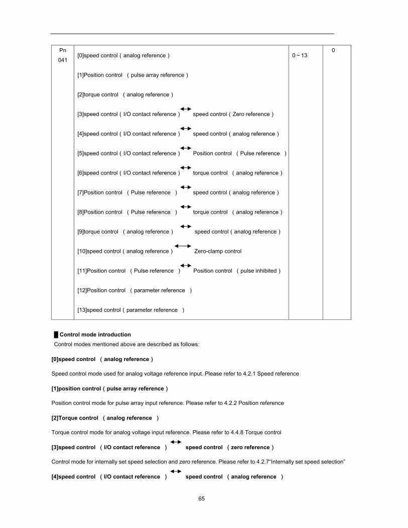
65
Pn
041 [0]speed control(analog reference)
[1]Position control (pulse array reference)
[2]torque control (analog reference)
[3]speed control(I/O contact reference) speed control(Zero reference)
[4]speed control(I/O contact reference) speed control(analog reference)
[5]speed control(I/O contact reference) Position control (Pulse reference )
[6]speed control(I/O contact reference) torque control (analog reference)
[7]Position control (Pulse reference ) speed control(analog reference)
[8]Position control (Pulse reference ) torque control (analog reference)
[9]torque control (analog reference) speed control(analog reference)
[10]speed control(analog reference) Zero-clamp control
[11]Position control (Pulse reference ) Position control (pulse inhibited)
[12]Position control (parameter reference )
[13]speed control(parameter reference )
0~13 0
Control mode introduction Control modes mentioned above are described as follows:
[0]speed control (analog reference)
Speed control mode used for analog voltage reference input. Please refer to 4.2.1 Speed reference
[1]position control(pulse array reference)
Position control mode for pulse array input reference. Please refer to 4.2.2 Position reference
[2]Torque control (analog reference )
Torque control mode for analog voltage input reference. Please refer to 4.4.8 Torque control
[3]speed control (I/O contact reference ) speed control (zero reference)
Control mode for internally set speed selection and zero reference. Please refer to 4.2.7“Internally set speed selection”
[4]speed control (I/O contact reference ) speed control (analog reference )
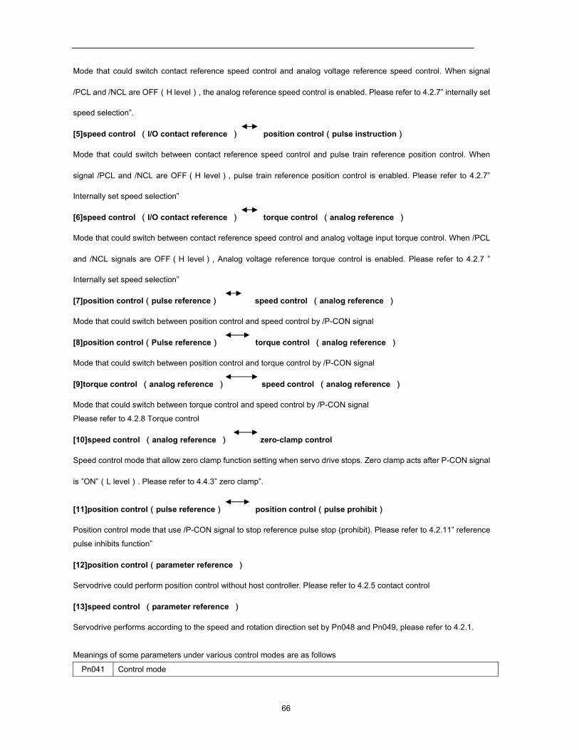
66
Mode that could switch contact reference speed control and analog voltage reference speed control. When signal
/PCL and /NCL are OFF(H level), the analog reference speed control is enabled. Please refer to 4.2.7” internally set
speed selection”.
[5]speed control (I/O contact reference ) position control(pulse instruction)
Mode that could switch between contact reference speed control and pulse train reference position control. When
signal /PCL and /NCL are OFF(H level), pulse train reference position control is enabled. Please refer to 4.2.7”
Internally set speed selection”
[6]speed control (I/O contact reference ) torque control (analog reference )
Mode that could switch between contact reference speed control and analog voltage input torque control. When /PCL
and /NCL signals are OFF(H level), Analog voltage reference torque control is enabled. Please refer to 4.2.7 ”
Internally set speed selection”
[7]position control(pulse reference) speed control (analog reference )
Mode that could switch between position control and speed control by /P-CON signal
[8]position control(Pulse reference) torque control (analog reference )
Mode that could switch between position control and torque control by /P-CON signal
[9]torque control (analog reference ) speed control (analog reference )
Mode that could switch between torque control and speed control by /P-CON signal
Please refer to 4.2.8 Torque control
[10]speed control (analog reference ) zero-clamp control
Speed control mode that allow zero clamp function setting when servo drive stops. Zero clamp acts after P-CON signal
is ”ON”(L level). Please refer to 4.4.3” zero clamp”.
[11]position control(pulse reference) position control(pulse prohibit)
Position control mode that use /P-CON signal to stop reference pulse stop (prohibit). Please refer to 4.2.11” reference
pulse inhibits function”
[12]position control(parameter reference )
Servodrive could perform position control without host controller. Please refer to 4.2.5 contact control
[13]speed control (parameter reference )
Servodrive performs according to the speed and rotation direction set by Pn048 and Pn049, please refer to 4.2.1.
Meanings of some parameters under various control modes are as follows
Pn041 Control mode
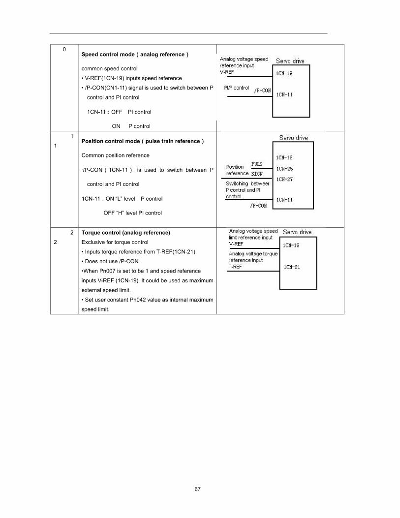
67
0 Speed control mode(analog reference)
common speed control
• V-REF(1CN-19) inputs speed reference
• /P-CON(CN1-11) signal is used to switch between P
control and PI control
1CN-11:OFF PI control
ON P control
1
1 Position control mode(pulse train reference)
Common position reference
·/P-CON(1CN-11) is used to switch between P
control and PI control
1CN-11:ON “L” level P control
OFF “H” level PI control
2
2
Torque control (analog reference) Exclusive for torque control
• Inputs torque reference from T-REF(1CN-21)
• Does not use /P-CON
•When Pn007 is set to be 1 and speed reference
inputs V-REF (1CN-19). It could be used as maximum
external speed limit.
• Set user constant Pn042 value as internal maximum
speed limit.
68
3 Speed control ( Contact reference<->zero
reference)
Switching speed control between contact reference
and zero reference
•Switching internally set speed by
/P-CON(1CN-11),/PCL(1CN-16) and /NCL(1CN-17)
/P-CON /PCL /NCL Speed
- 0 0 Zero
speed
0:Forward
rotation
1:Reverse
rotation
0 1 SPEED
1
1 1 SPEED
2
1 0 SPEED
3
4 Speed control mode(contact reference<->analog
reference)
Switching between contact control and analog
reference control
• Inputs analog from V-REF(1CN-19)
• Select control mold and internal speed by
/PCL(1CN-16) and /NCL(1CN-17)
/P-CON /PCL /NCL
P/PI
control
switching
0 0 Analog speed
reference control
0:Forward
rotation
1:Reverse
rotation
0 1 SPEED1
1 1 SPEED2
1 0 SPEED3
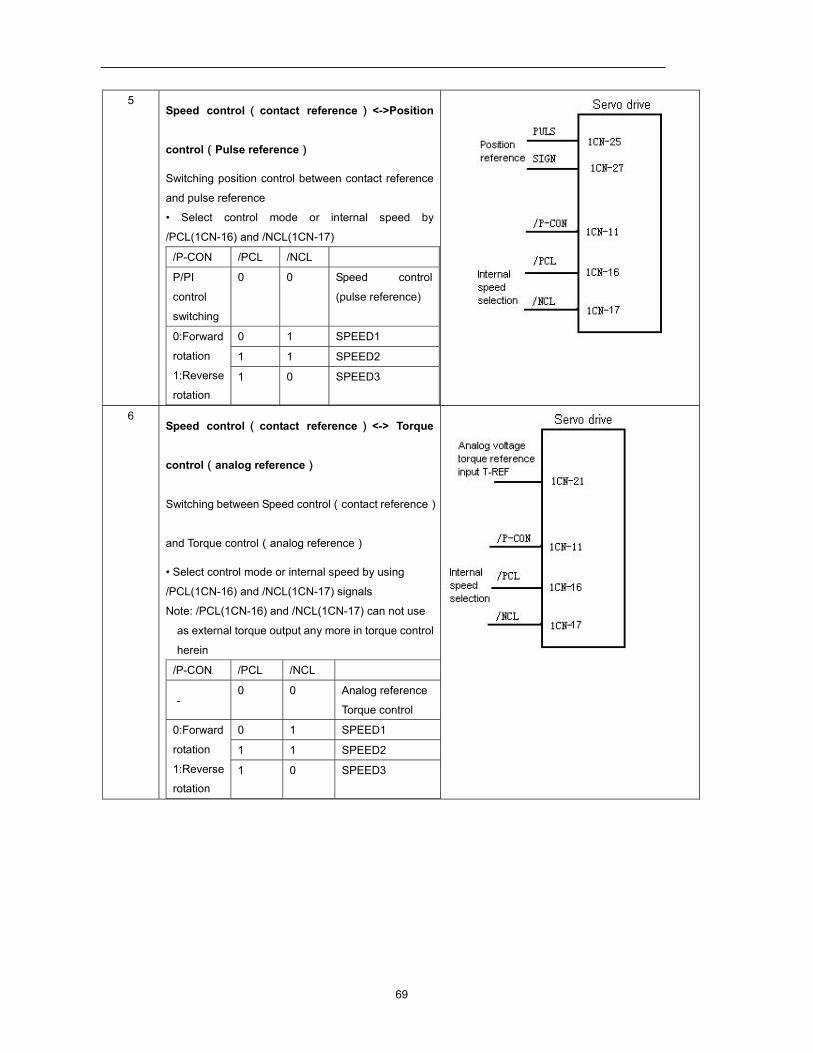
69
5 Speed control ( contact reference ) <->Position
control(Pulse reference)
Switching position control between contact reference
and pulse reference
• Select control mode or internal speed by
/PCL(1CN-16) and /NCL(1CN-17)
/P-CON /PCL /NCL
P/PI
control
switching
0 0 Speed control
(pulse reference)
0:Forward
rotation
1:Reverse
rotation
0 1 SPEED1
1 1 SPEED2
1 0 SPEED3
6 Speed control ( contact reference ) <-> Torque
control(analog reference)
Switching between Speed control(contact reference)
and Torque control(analog reference)
• Select control mode or internal speed by using
/PCL(1CN-16) and /NCL(1CN-17) signals
Note: /PCL(1CN-16) and /NCL(1CN-17) can not use
as external torque output any more in torque control
herein
/P-CON /PCL /NCL
- 0 0 Analog reference
Torque control
0:Forward
rotation
1:Reverse
rotation
0 1 SPEED1
1 1 SPEED2
1 0 SPEED3
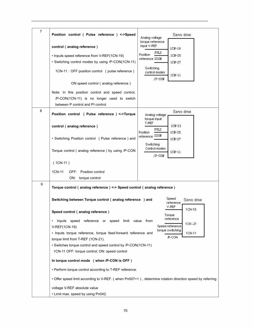
70
7 Position control ( Pulse reference ) <->Speed
control(analog reference)
• Inputs speed reference from V-REF(1CN-19)
• Switching control modes by using /P-CON(1CN-11)
1CN-11:OFF position control (pulse reference)
ON speed control(analog reference)
Note: In this position control and speed control,
/P-CON(1CN-11) is no longer used to switch
between P control and PI control
8 Position control ( Pulse reference ) <->Torque
control(analog reference)
• Switching Position control (Pulse reference)and
Torque control(analog reference)by using /P-CON
(1CN-11)
1CN-11 OFF: Position control
ON: torque control
9 Torque control(analog reference)<-> Speed control(analog reference)
Switching between Torque control(analog reference )and
Speed control(analog reference)
• Inputs speed reference or speed limit value from
V-REF(1CN-19)
• Inputs torque reference, torque feed-forward reference and
torque limit from T-REF (1CN-21).
• Switches torque control and speed control by /P-CON(1CN-11)
1CN-11 OFF: torque control; ON: speed control
In torque control mode (when /P-CON is OFF)
• Perform torque control according to T-REF reference.
• Offer speed limit according to V-REF.(when Pn007=1), determine rotation direction speed by referring
voltage V-REF absolute value
• Limit max. speed by using Pn042.
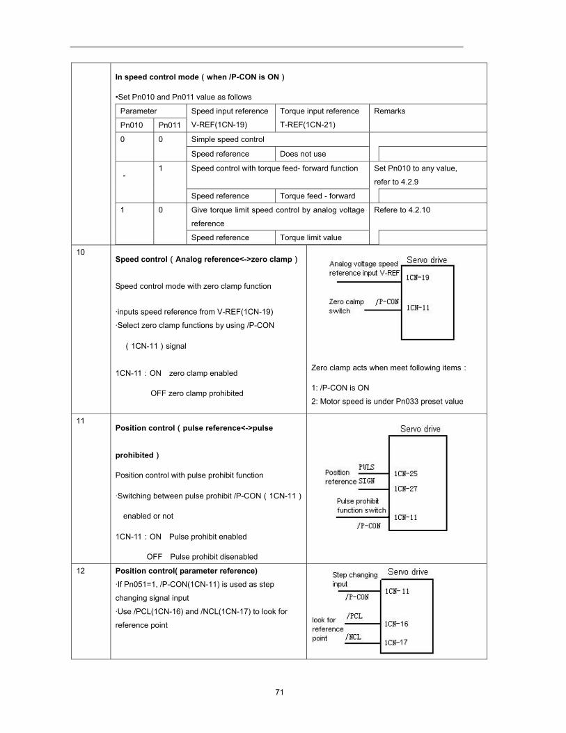
71
In speed control mode(when /P-CON is ON)
•Set Pn010 and Pn011 value as follows
Parameter Speed input reference
V-REF(1CN-19)
Torque input reference
T-REF(1CN-21)
Remarks
Pn010 Pn011
0 0 Simple speed control
Speed reference Does not use
- 1 Speed control with torque feed- forward function Set Pn010 to any value,
refer to 4.2.9
Speed reference Torque feed - forward
1 0 Give torque limit speed control by analog voltage
reference
Refere to 4.2.10
Speed reference Torque limit value
10 Speed control(Analog reference<->zero clamp)
Speed control mode with zero clamp function
·inputs speed reference from V-REF(1CN-19)
·Select zero clamp functions by using /P-CON
(1CN-11)signal
1CN-11:ON zero clamp enabled
OFF zero clamp prohibited
Zero clamp acts when meet following items:
1: /P-CON is ON
2: Motor speed is under Pn033 preset value
11 Position control(pulse reference<->pulse
prohibited)
Position control with pulse prohibit function
·Switching between pulse prohibit /P-CON(1CN-11)
enabled or not
1CN-11:ON Pulse prohibit enabled
OFF Pulse prohibit disenabled
12 Position control( parameter reference) ·If Pn051=1, /P-CON(1CN-11) is used as step
changing signal input
·Use /PCL(1CN-16) and /NCL(1CN-17) to look for
reference point
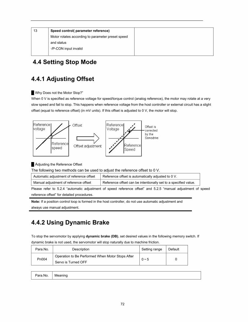
72
13 Speed control( parameter reference) Motor rotates according to parameter preset speed
and status
·/P-CON input invalid
4.4 Setting Stop Mode
4.4.1 Adjusting Offset
Why Does not the Motor Stop?”
When 0 V is specified as reference voltage for speed/torque control (analog reference), the motor may rotate at a very
slow speed and fail to stop. This happens when reference voltage from the host controller or external circuit has a slight
offset (equal to reference offset) (in mV units). If this offset is adjusted to 0 V, the motor will stop.
Adjusting the Reference Offset
The following two methods can be used to adjust the reference offset to 0 V. Automatic adjustment of reference offset Reference offset is automatically adjusted to 0 V. Manual adjustment of reference offset Reference offset can be intentionally set to a specified value.
Please refer to 5.2.4 “automatic adjustment of speed reference offset” and 5.2.5 “manual adjustment of speed
reference offset” for detailed procedures.
Note: If a position control loop is formed in the host controller, do not use automatic adjustment and
always use manual adjustment.
4.4.2 Using Dynamic Brake
To stop the servomotor by applying dynamic brake (DB), set desired values in the following memory switch. If
dynamic brake is not used, the servomotor will stop naturally due to machine friction.
Para.No. Description Setting range Default
Pn004 Operation to Be Performed When Motor Stops After
Servo is Turned OFF 0~5 0
Para.No. Meaning
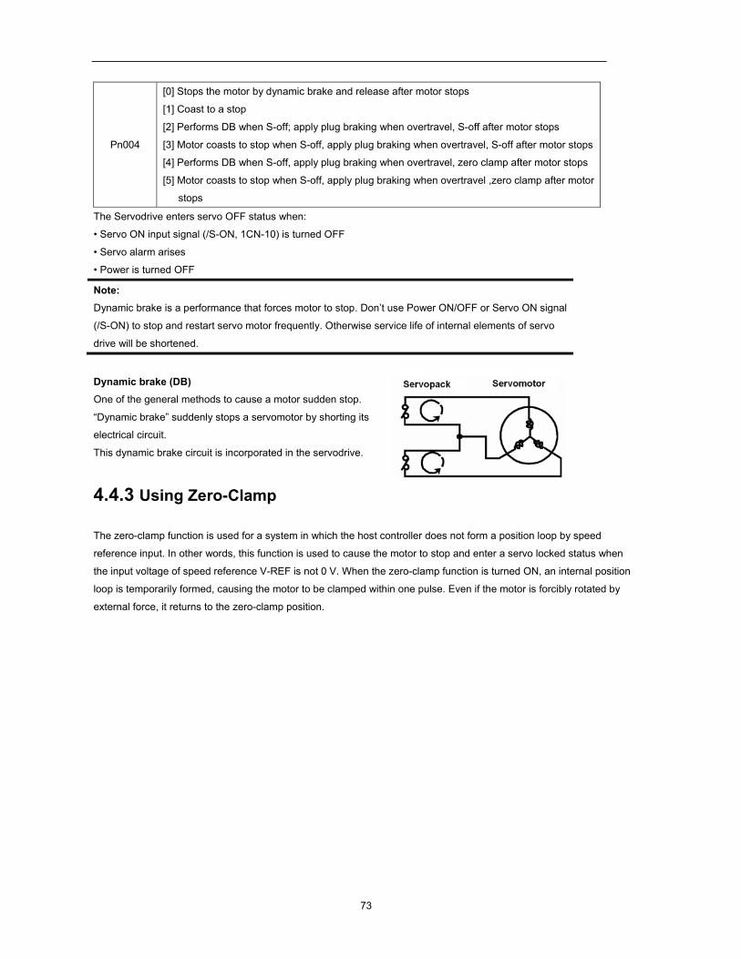
73
Pn004
[0] Stops the motor by dynamic brake and release after motor stops [1] Coast to a stop
[2] Performs DB when S-off; apply plug braking when overtravel, S-off after motor stops
[3] Motor coasts to stop when S-off, apply plug braking when overtravel, S-off after motor stops
[4] Performs DB when S-off, apply plug braking when overtravel, zero clamp after motor stops
[5] Motor coasts to stop when S-off, apply plug braking when overtravel ,zero clamp after motor
stops
The Servodrive enters servo OFF status when:
• Servo ON input signal (/S-ON, 1CN-10) is turned OFF
• Servo alarm arises
• Power is turned OFF
Note: Dynamic brake is a performance that forces motor to stop. Don’t use Power ON/OFF or Servo ON signal
(/S-ON) to stop and restart servo motor frequently. Otherwise service life of internal elements of servo
drive will be shortened.
Dynamic brake (DB) One of the general methods to cause a motor sudden stop.
“Dynamic brake” suddenly stops a servomotor by shorting its
electrical circuit.
This dynamic brake circuit is incorporated in the servodrive.
4.4.3 Using Zero-Clamp
The zero-clamp function is used for a system in which the host controller does not form a position loop by speed
reference input. In other words, this function is used to cause the motor to stop and enter a servo locked status when
the input voltage of speed reference V-REF is not 0 V. When the zero-clamp function is turned ON, an internal position
loop is temporarily formed, causing the motor to be clamped within one pulse. Even if the motor is forcibly rotated by
external force, it returns to the zero-clamp position.
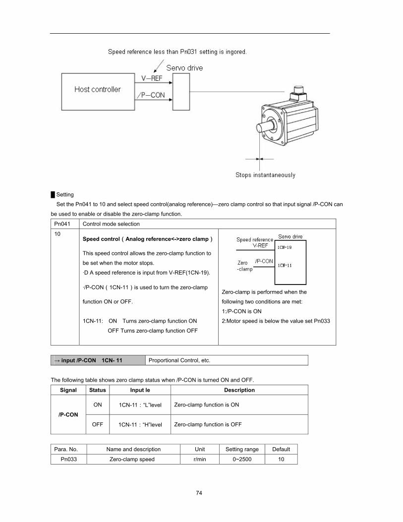
74
Setting
Set the Pn041 to 10 and select speed control(analog reference)—zero clamp control so that input signal /P-CON can
be used to enable or disable the zero-clamp function.
Pn041 Control mode selection
10 Speed control(Analog reference<->zero clamp)
This speed control allows the zero-clamp function to
be set when the motor stops.
·D A speed reference is input from V-REF(1CN-19).
·/P-CON(1CN-11)is used to turn the zero-clamp
function ON or OFF.
1CN-11: ON Turns zero-clamp function ON
OFF Turns zero-clamp function OFF
Zero-clamp is performed when the
following two conditions are met: 1:/P-CON is ON 2:Motor speed is below the value set Pn033
→ input /P-CON 1CN- 11 Proportional Control, etc.
The following table shows zero clamp status when /P-CON is turned ON and OFF.
Signal Status Input le Description
/P-CON
ON 1CN-11:“L”level Zero-clamp function is ON
OFF 1CN-11:“H”level Zero-clamp function is OFF
Para. No. Name and description Unit Setting range Default
Pn033 Zero-clamp speed r/min 0~2500 10
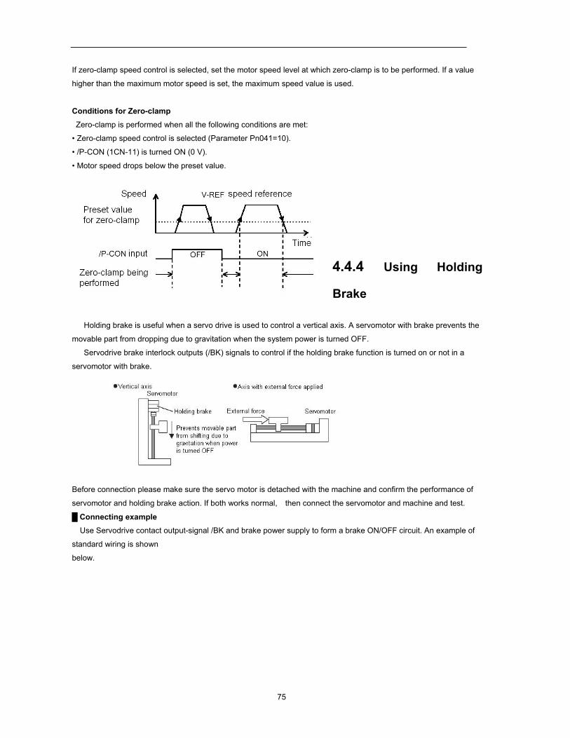
75
If zero-clamp speed control is selected, set the motor speed level at which zero-clamp is to be performed. If a value
higher than the maximum motor speed is set, the maximum speed value is used.
Conditions for Zero-clamp
Zero-clamp is performed when all the following conditions are met:
• Zero-clamp speed control is selected (Parameter Pn041=10).
• /P-CON (1CN-11) is turned ON (0 V).
• Motor speed drops below the preset value.
4.4.4 Using Holding
Brake
Holding brake is useful when a servo drive is used to control a vertical axis. A servomotor with brake prevents the
movable part from dropping due to gravitation when the system power is turned OFF.
Servodrive brake interlock outputs (/BK) signals to control if the holding brake function is turned on or not in a
servomotor with brake.
Before connection please make sure the servo motor is detached with the machine and confirm the performance of
servomotor and holding brake action. If both works normal, then connect the servomotor and machine and test.
Connecting example
Use Servodrive contact output-signal /BK and brake power supply to form a brake ON/OFF circuit. An example of
standard wiring is shown
below.
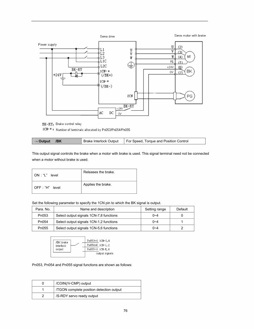
76
→ Output /BK Brake Interlock Output For Speed, Torque and Position Control
This output signal controls the brake when a motor with brake is used. This signal terminal need not be connected
when a motor without brake is used.
ON:“L” level Releases the brake.
OFF:“H” level Applies the brake.
Set the following parameter to specify the 1CN pin to which the BK signal is output.
Para. No. Name and description Setting range Default
Pn053 Select output signals 1CN-7,8 functions 0~4 0
Pn054 Select output signals 1CN-1,2 functions 0~4 1
Pn055 Select output signals 1CN-5,6 functions 0~4 2
Pn053, Pn054 and Pn055 signal functions are shown as follows:
0 /COIN(/V-CMP) output
1 /TGON complete position detection output
2 /S-RDY servo ready output
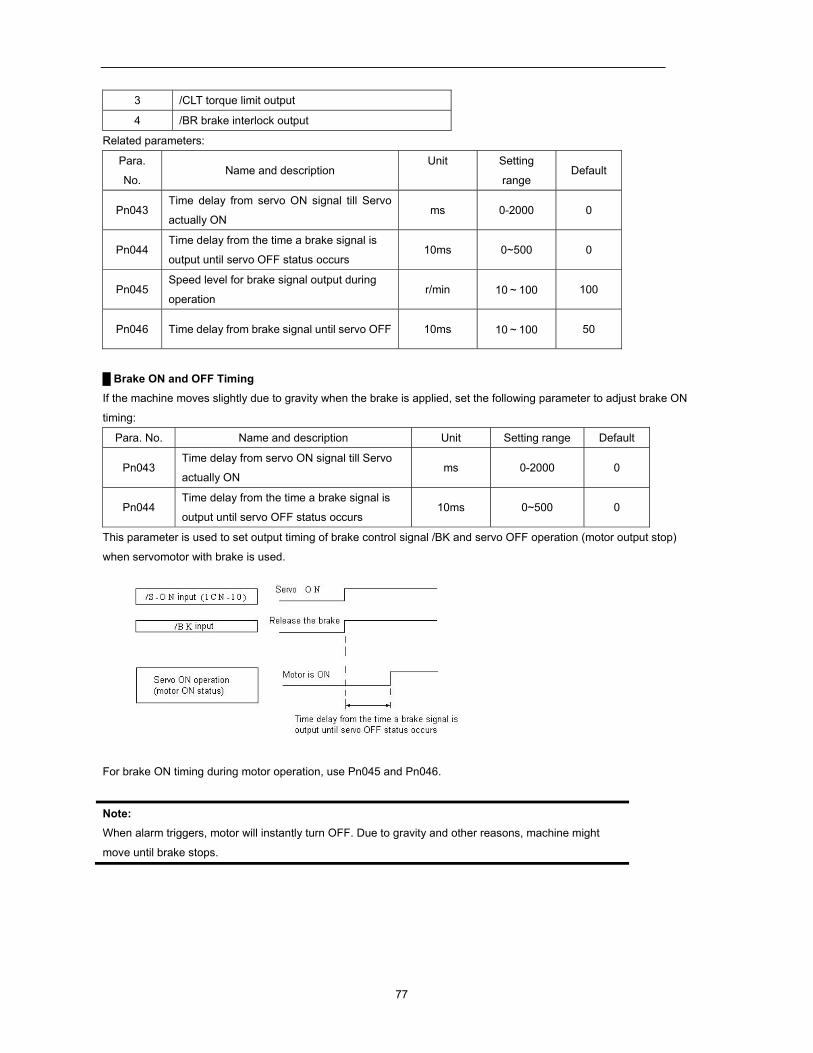
77
3 /CLT torque limit output
4 /BR brake interlock output
Related parameters:
Para.
No. Name and description
Unit Setting
range Default
Pn043 Time delay from servo ON signal till Servo
actually ON ms 0-2000 0
Pn044 Time delay from the time a brake signal is
output until servo OFF status occurs 10ms 0~500 0
Pn045 Speed level for brake signal output during
operation r/min 10~100 100
Pn046 Time delay from brake signal until servo OFF 10ms 10~100 50
Brake ON and OFF Timing If the machine moves slightly due to gravity when the brake is applied, set the following parameter to adjust brake ON
timing:
Para. No. Name and description Unit Setting range Default
Pn043 Time delay from servo ON signal till Servo
actually ON ms 0-2000 0
Pn044 Time delay from the time a brake signal is
output until servo OFF status occurs 10ms 0~500 0
This parameter is used to set output timing of brake control signal /BK and servo OFF operation (motor output stop)
when servomotor with brake is used.
For brake ON timing during motor operation, use Pn045 and Pn046.
Note: When alarm triggers, motor will instantly turn OFF. Due to gravity and other reasons, machine might
move until brake stops.
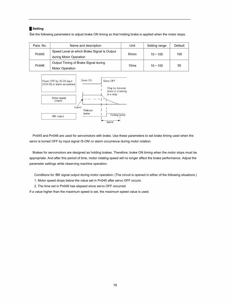
78
Setting
Set the following parameters to adjust brake ON timing so that holding brake is applied when the motor stops.
Para. No. Name and description Unit Setting range Default
Pn045 Speed Level at which Brake Signal Is Output
during Motor Operation R/min 10~100 100
Pn046 Output Timing of Brake Signal during
Motor Operation 10ms 10~100 50
Pn045 and Pn046 are used for servomotors with brake. Use these parameters to set brake timing used when the
servo is turned OFF by input signal /S-ON\ or alarm occurrence during motor rotation.
Brakes for servomotors are designed as holding brakes. Therefore, brake ON timing when the motor stops must be
appropriate. And after this period of time, motor rotating speed will no longer affect the brake performance. Adjust the
parameter settings while observing machine operation.
Conditions for /BK signal output during motor operation: (The circuit is opened in either of the following situations.)
1. Motor speed drops below the value set in Pn045 after servo OFF occurs.
2. The time set in Pn046 has elapsed since servo OFF occurred.
If a value higher than the maximum speed is set, the maximum speed value is used.
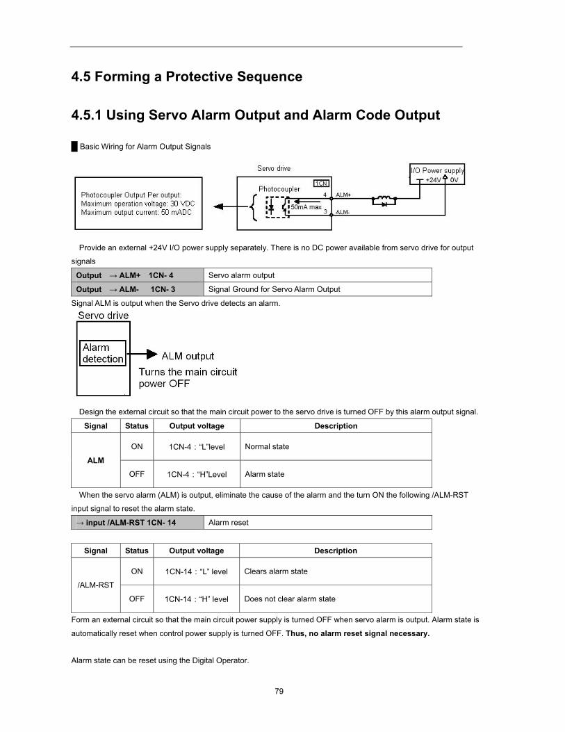
79
4.5 Forming a Protective Sequence
4.5.1 Using Servo Alarm Output and Alarm Code Output
Basic Wiring for Alarm Output Signals
Provide an external +24V I/O power supply separately. There is no DC power available from servo drive for output
signals
Output → ALM+ 1CN- 4 Servo alarm output
Output → ALM- 1CN- 3 Signal Ground for Servo Alarm Output
Signal ALM is output when the Servo drive detects an alarm.
Design the external circuit so that the main circuit power to the servo drive is turned OFF by this alarm output signal.
Signal Status Output voltage Description
ALM
ON 1CN-4:“L”level Normal state
OFF 1CN-4:“H”Level Alarm state
When the servo alarm (ALM) is output, eliminate the cause of the alarm and the turn ON the following /ALM-RST
input signal to reset the alarm state.
→ input /ALM-RST 1CN- 14 Alarm reset
Signal Status Output voltage Description
/ALM-RST
ON 1CN-14:“L” level Clears alarm state
OFF 1CN-14:“H” level Does not clear alarm state
Form an external circuit so that the main circuit power supply is turned OFF when servo alarm is output. Alarm state is
automatically reset when control power supply is turned OFF. Thus, no alarm reset signal necessary.
Alarm state can be reset using the Digital Operator.
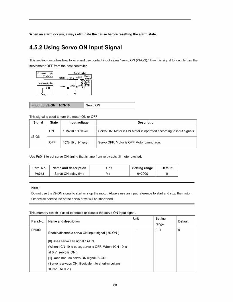
80
When an alarm occurs, always eliminate the cause before resetting the alarm state.
4.5.2 Using Servo ON Input Signal
This section describes how to wire and use contact input signal “servo ON (/S-ON).” Use this signal to forcibly turn the
servomotor OFF from the host controller.
→ output /S-ON 1CN-10 Servo ON
This signal is used to turn the motor ON or OFF
Signal State Input voltage Description
/S-ON
ON 1CN-10:“L”level Servo ON: Motor is ON Motor is operated according to input signals.
OFF 1CN-10:“H”level Servo OFF: Motor is OFF Motor cannot run.
Use Pn043 to set servo ON timing that is time from relay acts till motor excited.
Para. No. Name and description Unit Setting range Default
Pn043 Servo ON delay time Ms 0~2000 0
Note: Do not use the /S-ON signal to start or stop the motor. Always use an input reference to start and stop the motor.
Otherwise service life of the servo drive will be shortened.
This memory switch is used to enable or disable the servo ON input signal.
Para.No. Name and description Unit Setting
range Default
Pn000 Enable/disenable servo ON input signal(/S-ON)
[0] Uses servo ON signal /S-ON.
(When 1CN-10 is open, servo is OFF. When 1CN-10 is
at 0 V, servo is ON.)
[1] Does not use servo ON signal /S-ON.
(Servo is always ON. Equivalent to short-circuiting
1CN-10 to 0 V.)
— 0~1 0
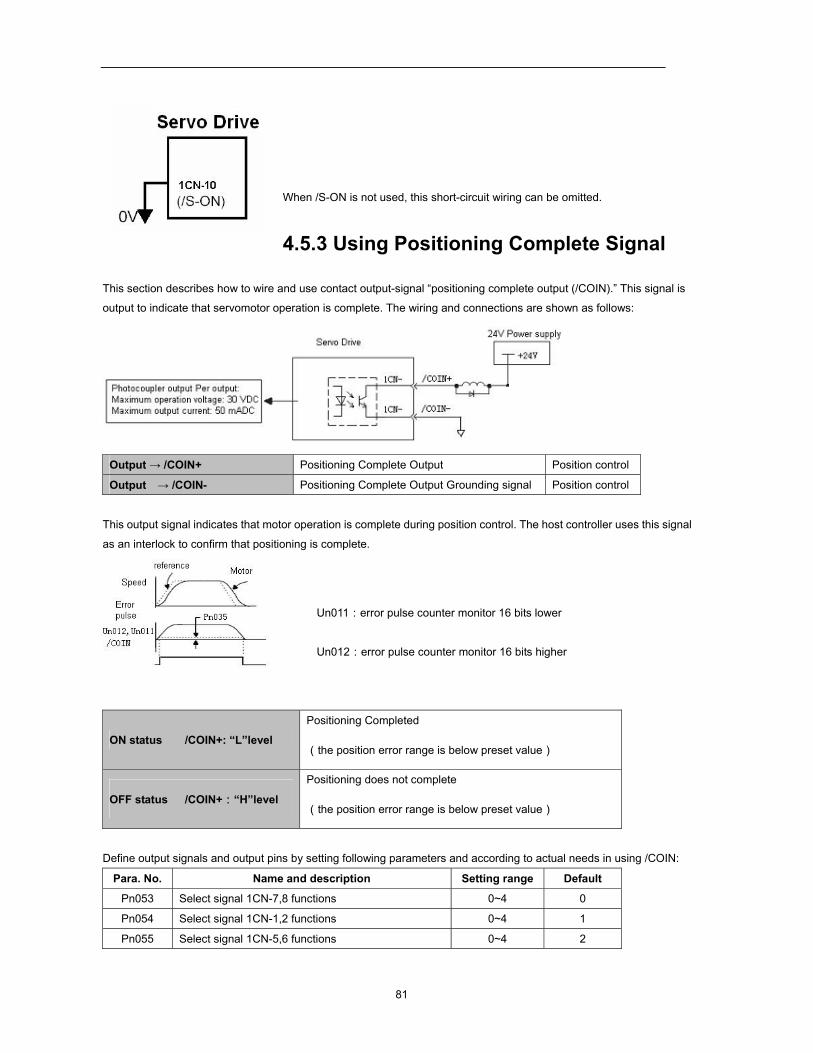
81
When /S-ON is not used, this short-circuit wiring can be omitted.
4.5.3 Using Positioning Complete Signal
This section describes how to wire and use contact output-signal “positioning complete output (/COIN).” This signal is
output to indicate that servomotor operation is complete. The wiring and connections are shown as follows:
Output → /COIN+ Positioning Complete Output Position control
Output → /COIN- Positioning Complete Output Grounding signal Position control
This output signal indicates that motor operation is complete during position control. The host controller uses this signal
as an interlock to confirm that positioning is complete.
Un011:error pulse counter monitor 16 bits lower
Un012:error pulse counter monitor 16 bits higher
ON status /COIN+: “L”level
Positioning Completed
(the position error range is below preset value)
OFF status /COIN+:“H”level
Positioning does not complete
(the position error range is below preset value)
Define output signals and output pins by setting following parameters and according to actual needs in using /COIN:
Para. No. Name and description Setting range Default
Pn053 Select signal 1CN-7,8 functions 0~4 0
Pn054 Select signal 1CN-1,2 functions 0~4 1
Pn055 Select signal 1CN-5,6 functions 0~4 2

82
Pn053, Pn054 and Pn055 functions are as follows:
0 /COIN(/V-CMP) output
1 /TGON running signal output
2 /S-RDY servo ready output
3 /CLT torque limit output
4 BK brake interlock output
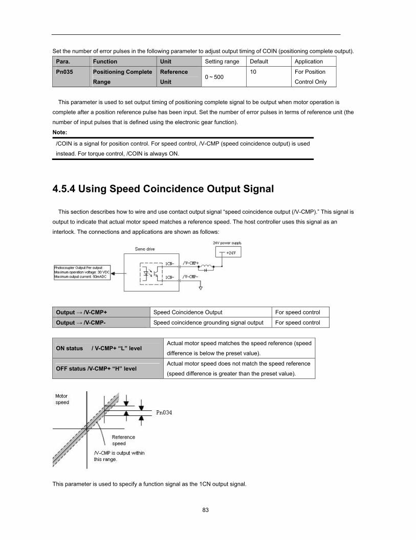
83
Set the number of error pulses in the following parameter to adjust output timing of COIN (positioning complete output).
Para. Function Unit Setting range Default Application
Pn035 Positioning Complete
Range
Reference
Unit 0~500
10 For Position
Control Only
This parameter is used to set output timing of positioning complete signal to be output when motor operation is
complete after a position reference pulse has been input. Set the number of error pulses in terms of reference unit (the
number of input pulses that is defined using the electronic gear function).
Note:
/COIN is a signal for position control. For speed control, /V-CMP (speed coincidence output) is used
instead. For torque control, /COIN is always ON.
4.5.4 Using Speed Coincidence Output Signal
This section describes how to wire and use contact output signal “speed coincidence output (/V-CMP).” This signal is
output to indicate that actual motor speed matches a reference speed. The host controller uses this signal as an
interlock. The connections and applications are shown as follows:
Output → /V-CMP+ Speed Coincidence Output For speed control
Output → /V-CMP- Speed coincidence grounding signal output For speed control
ON status / V-CMP+ “L” level Actual motor speed matches the speed reference (speed
difference is below the preset value).
OFF status /V-CMP+ “H” level Actual motor speed does not match the speed reference
(speed difference is greater than the preset value).
This parameter is used to specify a function signal as the 1CN output signal.
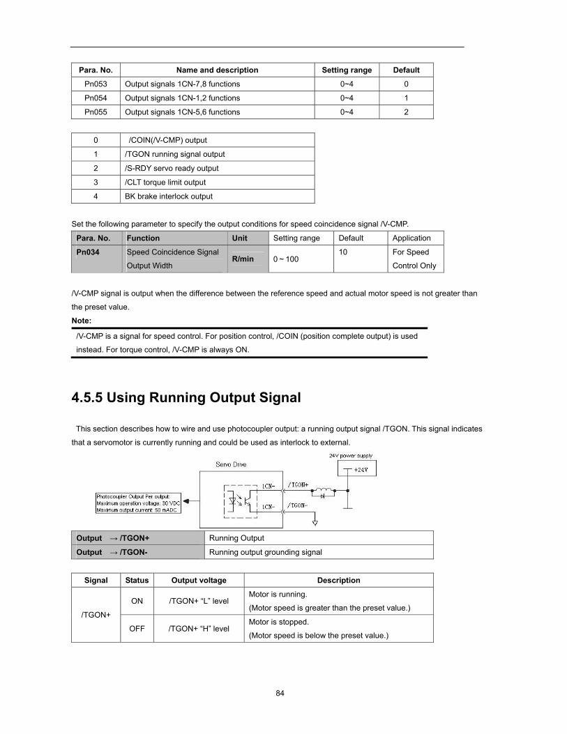
84
Para. No. Name and description Setting range Default
Pn053 Output signals 1CN-7,8 functions 0~4 0
Pn054 Output signals 1CN-1,2 functions 0~4 1
Pn055 Output signals 1CN-5,6 functions 0~4 2
0 /COIN(/V-CMP) output
1 /TGON running signal output
2 /S-RDY servo ready output
3 /CLT torque limit output
4 BK brake interlock output
Set the following parameter to specify the output conditions for speed coincidence signal /V-CMP.
Para. No. Function Unit Setting range Default Application
Pn034 Speed Coincidence Signal
Output Width R/min 0~100
10 For Speed
Control Only
/V-CMP signal is output when the difference between the reference speed and actual motor speed is not greater than
the preset value.
Note:
/V-CMP is a signal for speed control. For position control, /COIN (position complete output) is used
instead. For torque control, /V-CMP is always ON.
4.5.5 Using Running Output Signal
This section describes how to wire and use photocoupler output: a running output signal /TGON. This signal indicates
that a servomotor is currently running and could be used as interlock to external.
Output → /TGON+ Running Output Output → /TGON- Running output grounding signal
Signal Status Output voltage Description
/TGON+
ON /TGON+ “L” level Motor is running.
(Motor speed is greater than the preset value.)
OFF /TGON+ “H” level Motor is stopped.
(Motor speed is below the preset value.)
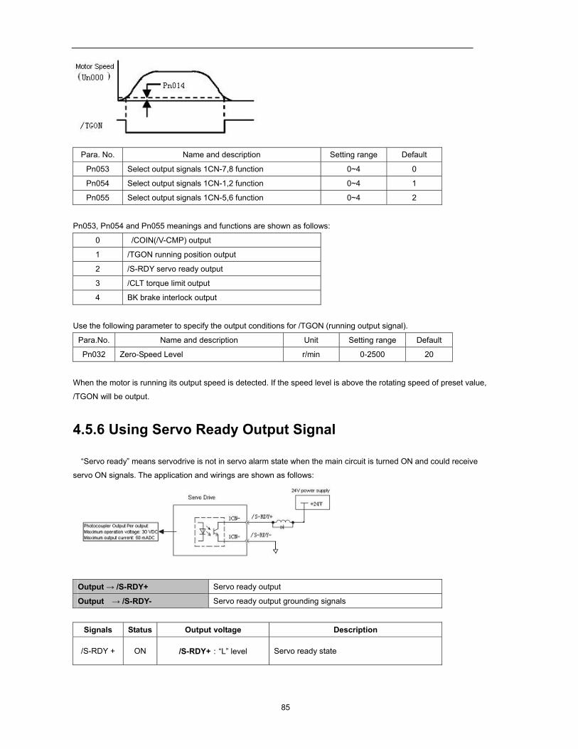
85
Para. No. Name and description Setting range Default
Pn053 Select output signals 1CN-7,8 function 0~4 0
Pn054 Select output signals 1CN-1,2 function 0~4 1
Pn055 Select output signals 1CN-5,6 function 0~4 2
Pn053, Pn054 and Pn055 meanings and functions are shown as follows:
0 /COIN(/V-CMP) output
1 /TGON running position output
2 /S-RDY servo ready output
3 /CLT torque limit output
4 BK brake interlock output
Use the following parameter to specify the output conditions for /TGON (running output signal).
Para.No. Name and description Unit Setting range Default
Pn032 Zero-Speed Level r/min 0-2500 20
When the motor is running its output speed is detected. If the speed level is above the rotating speed of preset value,
/TGON will be output.
4.5.6 Using Servo Ready Output Signal
“Servo ready” means servodrive is not in servo alarm state when the main circuit is turned ON and could receive
servo ON signals. The application and wirings are shown as follows:
Output → /S-RDY+ Servo ready output
Output → /S-RDY- Servo ready output grounding signals
Signals Status Output voltage Description
/S-RDY + ON /S-RDY+:“L” level Servo ready state

86
OFF /S-RDY+:“H” level Not in servo ready state
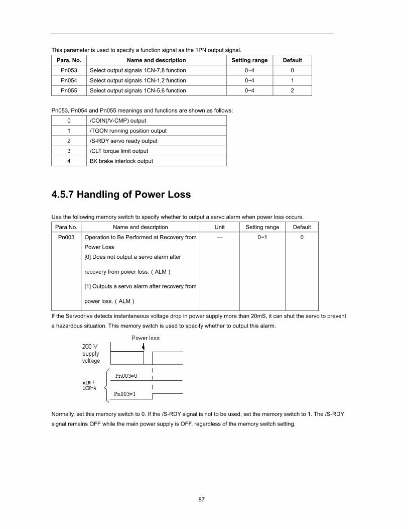
87
This parameter is used to specify a function signal as the 1PN output signal.
Para. No. Name and description Setting range Default
Pn053 Select output signals 1CN-7,8 function 0~4 0
Pn054 Select output signals 1CN-1,2 function 0~4 1
Pn055 Select output signals 1CN-5,6 function 0~4 2
Pn053, Pn054 and Pn055 meanings and functions are shown as follows:
0 /COIN(/V-CMP) output
1 /TGON running position output
2 /S-RDY servo ready output
3 /CLT torque limit output
4 BK brake interlock output
4.5.7 Handling of Power Loss
Use the following memory switch to specify whether to output a servo alarm when power loss occurs.
Para.No. Name and description Unit Setting range Default
Pn003 Operation to Be Performed at Recovery from
Power Loss
[0] Does not output a servo alarm after
recovery from power loss.(ALM)
[1] Outputs a servo alarm after recovery from
power loss.(ALM)
— 0~1 0
If the Servodrive detects instantaneous voltage drop in power supply more than 20mS, it can shut the servo to prevent
a hazardous situation. This memory switch is used to specify whether to output this alarm.
Normally, set this memory switch to 0. If the /S-RDY signal is not to be used, set the memory switch to 1. The /S-RDY
signal remains OFF while the main power supply is OFF, regardless of the memory switch setting.
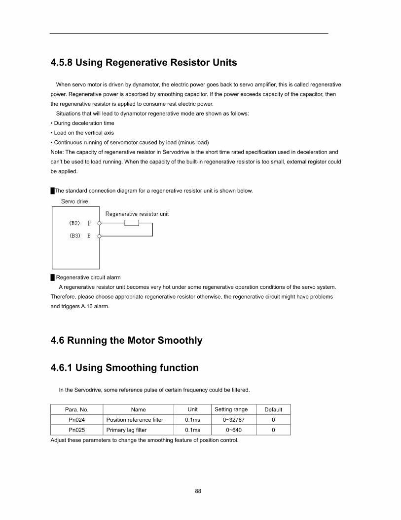
88
4.5.8 Using Regenerative Resistor Units
When servo motor is driven by dynamotor, the electric power goes back to servo amplifier, this is called regenerative
power. Regenerative power is absorbed by smoothing capacitor. If the power exceeds capacity of the capacitor, then
the regenerative resistor is applied to consume rest electric power.
Situations that will lead to dynamotor regenerative mode are shown as follows:
• During deceleration time
• Load on the vertical axis
• Continuous running of servomotor caused by load (minus load)
Note: The capacity of regenerative resistor in Servodrive is the short time rated specification used in deceleration and
can’t be used to load running. When the capacity of the built-in regenerative resistor is too small, external register could
be applied.
The standard connection diagram for a regenerative resistor unit is shown below.
Regenerative circuit alarm
A regenerative resistor unit becomes very hot under some regenerative operation conditions of the servo system.
Therefore, please choose appropriate regenerative resistor otherwise, the regenerative circuit might have problems
and triggers A.16 alarm.
4.6 Running the Motor Smoothly
4.6.1 Using Smoothing function
In the Servodrive, some reference pulse of certain frequency could be filtered.
Para. No. Name Unit Setting range Default
Pn024 Position reference filter 0.1ms 0~32767 0
Pn025 Primary lag filter 0.1ms 0~640 0
Adjust these parameters to change the smoothing feature of position control.
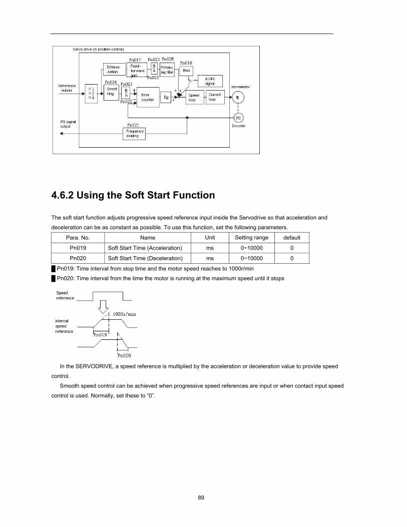
89
4.6.2 Using the Soft Start Function
The soft start function adjusts progressive speed reference input inside the Servodrive so that acceleration and
deceleration can be as constant as possible. To use this function, set the following parameters.
Para. No. Name Unit Setting range default
Pn019 Soft Start Time (Acceleration) ms 0~10000 0
Pn020 Soft Start Time (Deceleration) ms 0~10000 0
Pn019: Time interval from stop time and the motor speed reaches to 1000r/min
Pn020: Time interval from the time the motor is running at the maximum speed until it stops
In the SERVODRIVE, a speed reference is multiplied by the acceleration or deceleration value to provide speed
control.
Smooth speed control can be achieved when progressive speed references are input or when contact input speed
control is used. Normally, set these to “0”.
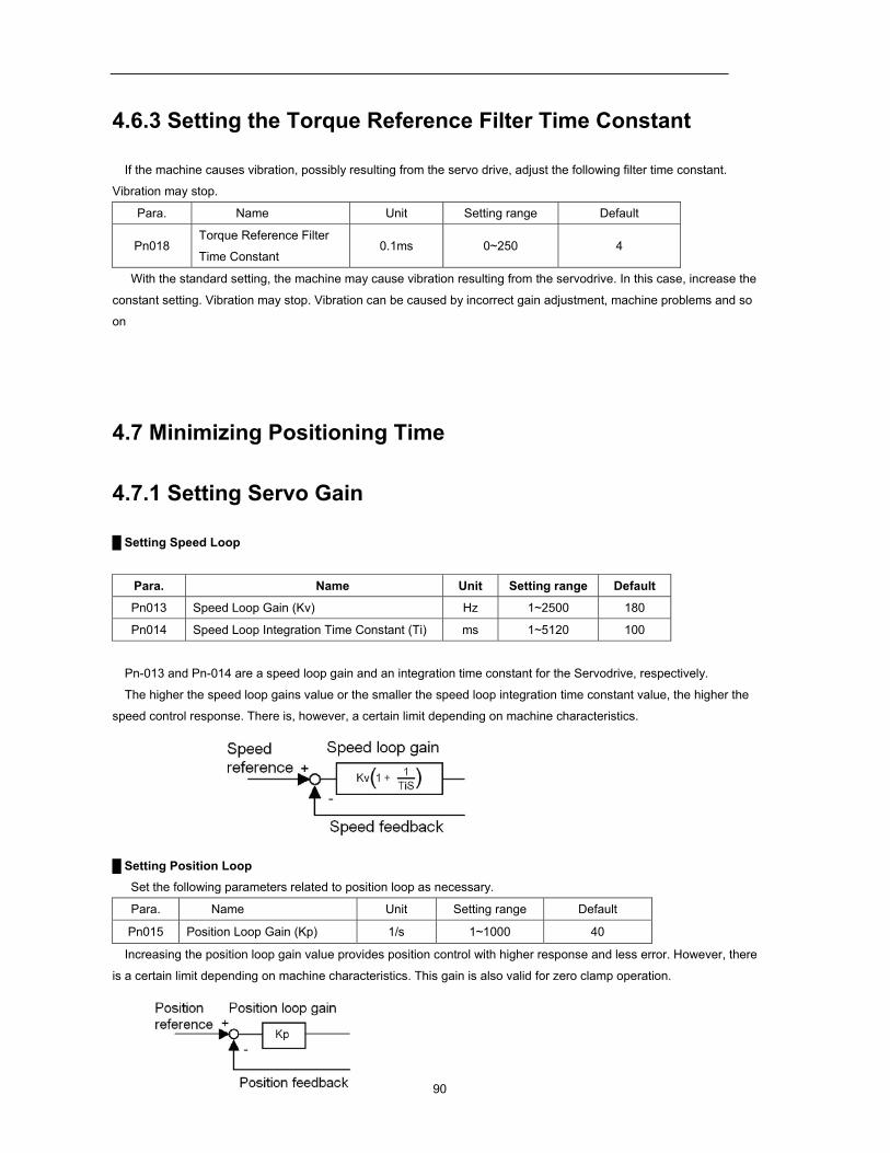
90
4.6.3 Setting the Torque Reference Filter Time Constant
If the machine causes vibration, possibly resulting from the servo drive, adjust the following filter time constant.
Vibration may stop.
Para. Name Unit Setting range Default
Pn018 Torque Reference Filter
Time Constant 0.1ms 0~250 4
With the standard setting, the machine may cause vibration resulting from the servodrive. In this case, increase the
constant setting. Vibration may stop. Vibration can be caused by incorrect gain adjustment, machine problems and so
on
4.7 Minimizing Positioning Time
4.7.1 Setting Servo Gain
Setting Speed Loop
Para. Name Unit Setting range Default
Pn013 Speed Loop Gain (Kv) Hz 1~2500 180
Pn014 Speed Loop Integration Time Constant (Ti) ms 1~5120 100
Pn-013 and Pn-014 are a speed loop gain and an integration time constant for the Servodrive, respectively.
The higher the speed loop gains value or the smaller the speed loop integration time constant value, the higher the
speed control response. There is, however, a certain limit depending on machine characteristics.
Setting Position Loop
Set the following parameters related to position loop as necessary.
Para. Name Unit Setting range Default
Pn015 Position Loop Gain (Kp) 1/s 1~1000 40
Increasing the position loop gain value provides position control with higher response and less error. However, there
is a certain limit depending on machine characteristics. This gain is also valid for zero clamp operation.
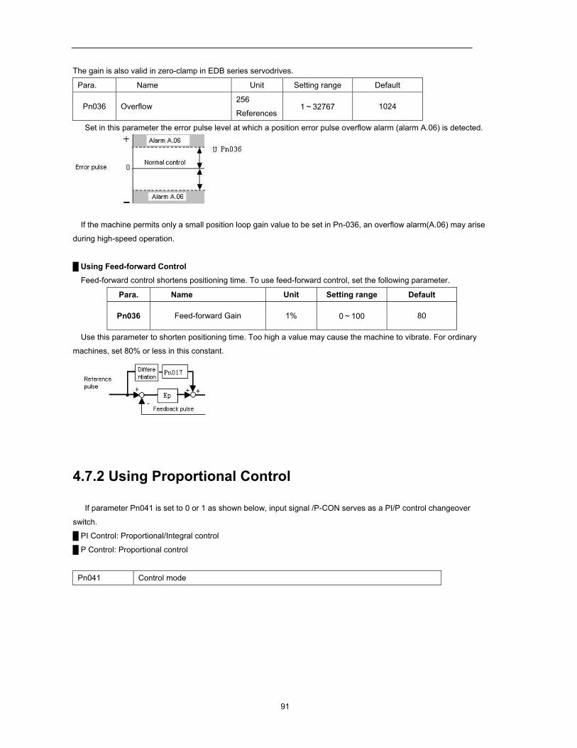
91
The gain is also valid in zero-clamp in EDB series servodrives.
Para. Name Unit Setting range Default
Pn036 Overflow 256
References 1~32767 1024
Set in this parameter the error pulse level at which a position error pulse overflow alarm (alarm A.06) is detected.
If the machine permits only a small position loop gain value to be set in Pn-036, an overflow alarm(A.06) may arise
during high-speed operation.
Using Feed-forward Control Feed-forward control shortens positioning time. To use feed-forward control, set the following parameter.
Para. Name Unit Setting range Default
Pn036 Feed-forward Gain 1% 0~100 80
Use this parameter to shorten positioning time. Too high a value may cause the machine to vibrate. For ordinary
machines, set 80% or less in this constant.
4.7.2 Using Proportional Control
If parameter Pn041 is set to 0 or 1 as shown below, input signal /P-CON serves as a PI/P control changeover
switch.
PI Control: Proportional/Integral control P Control: Proportional control
Pn041 Control mode
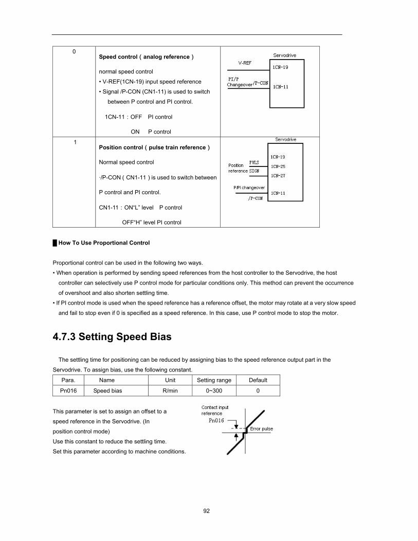
92
0 Speed control(analog reference)
normal speed control
• V-REF(1CN-19) input speed reference
• Signal /P-CON (CN1-11) is used to switch
between P control and PI control.
1CN-11:OFF PI control
ON P control
1 Position control(pulse train reference)
Normal speed control
·/P-CON(CN1-11)is used to switch between
P control and PI control.
CN1-11:ON“L” level P control
OFF“H” level PI control
How To Use Proportional Control
Proportional control can be used in the following two ways.
• When operation is performed by sending speed references from the host controller to the Servodrive, the host
controller can selectively use P control mode for particular conditions only. This method can prevent the occurrence
of overshoot and also shorten settling time.
• If PI control mode is used when the speed reference has a reference offset, the motor may rotate at a very slow speed
and fail to stop even if 0 is specified as a speed reference. In this case, use P control mode to stop the motor.
4.7.3 Setting Speed Bias
The settling time for positioning can be reduced by assigning bias to the speed reference output part in the
Servodrive. To assign bias, use the following constant.
Para. Name Unit Setting range Default
Pn016 Speed bias R/min 0~300 0
This parameter is set to assign an offset to a
speed reference in the Servodrive. (In
position control mode)
Use this constant to reduce the settling time.
Set this parameter according to machine conditions.
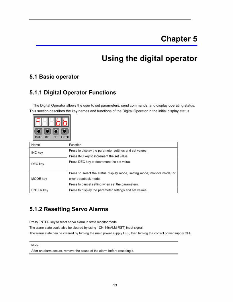
93
Chapter 5
Using the digital operator
5.1 Basic operator
5.1.1 Digital Operator Functions
The Digital Operator allows the user to set parameters, send commands, and display operating status. This section describes the key names and functions of the Digital Operator in the initial display status.
Name Function
INC key Press to display the parameter settings and set values.
Press INC key to increment the set value
Press DEC key to decrement the set value.
DEC key
MODE key
Press to select the status display mode, setting mode, monitor mode, or
error traceback mode.
Press to cancel setting when set the parameters.
ENTER key Press to display the parameter settings and set values.
5.1.2 Resetting Servo Alarms
Press ENTER key to reset servo alarm in state monitor mode
The alarm state could also be cleared by using 1CN-14(/ALM-RST) input signal.
The alarm state can be cleared by turning the main power supply OFF, then turning the control power supply OFF.
Note: After an alarm occurs, remove the cause of the alarm before resetting it.
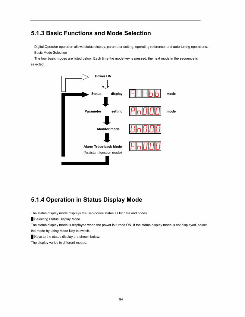
94
5.1.3 Basic Functions and Mode Selection
Digital Operator operation allows status display, parameter setting, operating reference, and auto-tuning operations.
Basic Mode Selection
The four basic modes are listed below. Each time the mode key is pressed, the next mode in the sequence is
selected.
Power ON
Status display mode
Parameter setting mode
Monitor mode
Alarm Trace-back Mode
(Assistant function mode)
5.1.4 Operation in Status Display Mode
The status display mode displays the Servodrive status as bit data and codes.
Selecting Status Display Mode
The status display mode is displayed when the power is turned ON. If the status display mode is not displayed, select
the mode by using Mode Key to switch.
Keys to the status display are shown below.
The display varies in different modes.
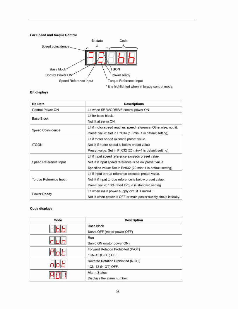
95
For Speed and torque Control Bit data Code
Speed coincidence
Base block TGON
Control Power ON Power ready
Speed Reference Input Torque Reference Input
* It is highlighted when in torque control mode.
Bit displays
Bit Data Descriptions
Control Power ON Lit when SERVODRIVE control power ON.
Base Block Lit for base block.
Not lit at servo ON.
Speed Coincidence Lit if motor speed reaches speed reference. Otherwise, not lit.
Preset value: Set in Pn034 (10 min−1 is default setting)
/TGON
Lit if motor speed exceeds preset value.
Not lit if motor speed is below preset value
Preset value: Set in Pn032 (20 min−1 is default setting)
Speed Reference Input
Lit if input speed reference exceeds preset value.
Not lit if input speed reference is below preset value.
Specified value: Set in Pn032 (20 min−1 is default setting)
Torque Reference Input
Lit if input torque reference exceeds preset value.
Not lit if input torque reference is below preset value.
Preset value: 10% rated torque is standard setting
Power Ready Lit when main power supply circuit is normal.
Not lit when power is OFF or main power supply circuit is faulty.
Code displays
Code Description
Base block
Servo OFF (motor power OFF)
Run
Servo ON (motor power ON)
Forward Rotation Prohibited (P-OT)
1CN-12 (P-OT) OFF.
Reverse Rotation Prohibited (N-OT)
1CN-13 (N-OT) OFF.
Alarm Status
Displays the alarm number.
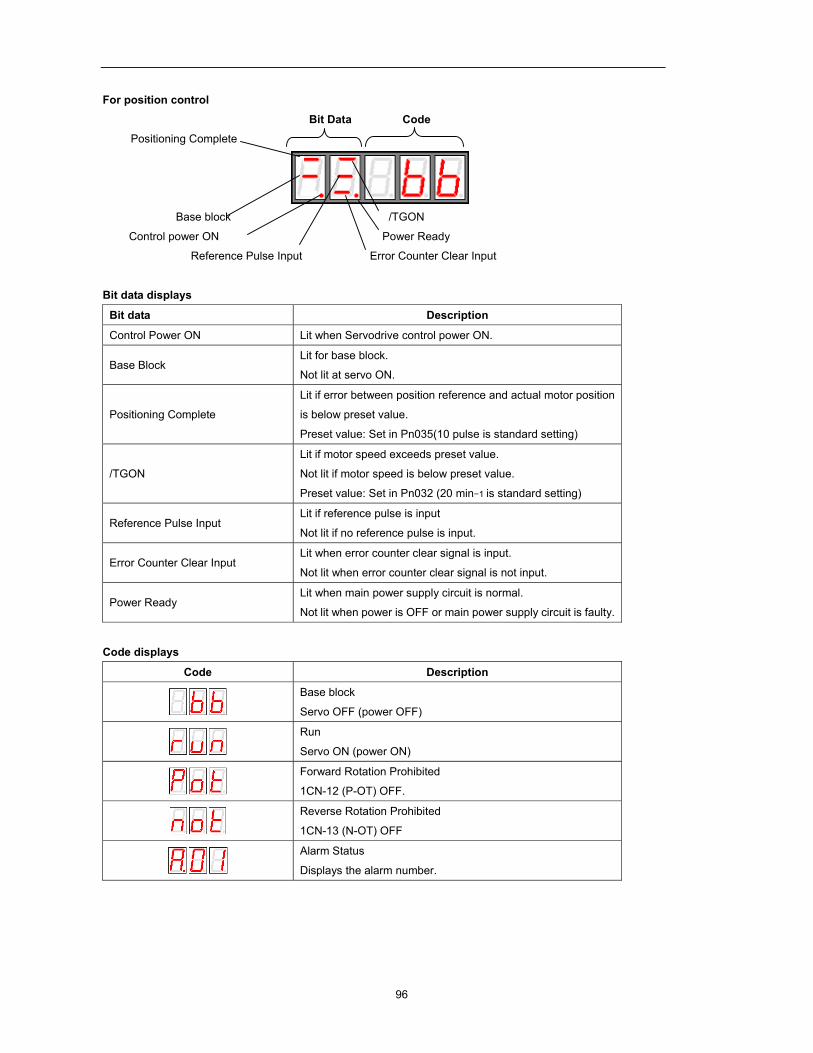
96
For position control
Bit Data Code
Positioning Complete
Base block /TGON
Control power ON Power Ready
Reference Pulse Input Error Counter Clear Input
Bit data displays
Bit data Description
Control Power ON Lit when Servodrive control power ON.
Base Block Lit for base block.
Not lit at servo ON.
Positioning Complete Lit if error between position reference and actual motor position
is below preset value.
Preset value: Set in Pn035(10 pulse is standard setting)
/TGON
Lit if motor speed exceeds preset value.
Not lit if motor speed is below preset value.
Preset value: Set in Pn032 (20 min−1 is standard setting)
Reference Pulse Input Lit if reference pulse is input
Not lit if no reference pulse is input.
Error Counter Clear Input Lit when error counter clear signal is input.
Not lit when error counter clear signal is not input.
Power Ready Lit when main power supply circuit is normal.
Not lit when power is OFF or main power supply circuit is faulty.
Code displays
Code Description
Base block
Servo OFF (power OFF)
Run
Servo ON (power ON)
Forward Rotation Prohibited
1CN-12 (P-OT) OFF.
Reverse Rotation Prohibited
1CN-13 (N-OT) OFF
Alarm Status
Displays the alarm number.
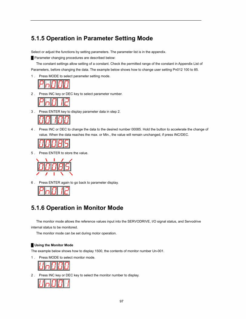
97
5.1.5 Operation in Parameter Setting Mode
Select or adjust the functions by setting parameters. The parameter list is in the appendix.
Parameter changing procedures are described below:
The constant settings allow setting of a constant. Check the permitted range of the constant in Appendix List of
Parameters, before changing the data. The example below shows how to change user setting Pn012 100 to 85.
1. Press MODE to select parameter setting mode.
2. Press INC key or DEC key to select parameter number.
3. Press ENTER key to display parameter data in step 2.
4. Press INC or DEC to change the data to the desired number 00085. Hold the button to accelerate the change of value. When the data reaches the max. or Min., the value will remain unchanged, if press INC/DEC.
5. Press ENTER to store the value.
6. Press ENTER again to go back to parameter display.
5.1.6 Operation in Monitor Mode
The monitor mode allows the reference values input into the SERVODRIVE, I/O signal status, and Servodrive
internal status to be monitored.
The monitor mode can be set during motor operation.
Using the Monitor Mode The example below shows how to display 1500, the contents of monitor number Un-001.
1. Press MODE to select monitor mode.
2. Press INC key or DEC key to select the monitor number to display.
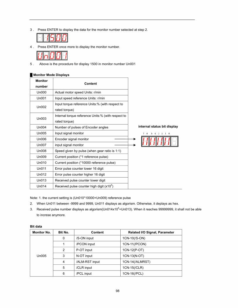
98
3. Press ENTER to display the data for the monitor number selected at step 2.
4. Press ENTER once more to display the monitor number.
5. Above is the procedure for display 1500 in monitor number Un001
Monitor Mode Displays
Monitor
number Content
internal status bit display
Un000 Actual motor speed Units: r/min Un001 Input speed reference Units: r/min
Un002 Input torque reference Units:% (with respect to
rated torque)
Un003 Internal torque reference Units:% (with respect to
rated torque) Un004 Number of pulses of Encoder angles Un005 Input signal monitor Un006 Encoder signal monitor
Un007 input signal monitor
Un008 Speed given by pulse (when gear ratio is 1:1)
Un009 Current position (*1 reference pulse)
Un010 Current position (*10000 reference pulse)
Un011 Error pulse counter lower 16 digit
Un012 Error pulse counter higher 16 digit
Un013 Received pulse counter lower digit
Un014 Received pulse counter high digit (x104)
Note: 1. the current setting is (Un010*10000+Un009) reference pulse
2. When Un011 between -9999 and 9999, Un011 displays as algorism. Otherwise, it deplays as hex.
3. Received pulse number displays as algorism(Un014x104+Un013). When it reaches 99999999, it shall not be able
to increse anymore.
Bit data
Monitor No. Bit No. Content Related I/O Signal, Parameter
Un005
0 /S-ON input 1CN-10(/S-ON)
1 /PCON input 1CN-11(/PCON)
2 P-OT input 1CN-12(P-OT)
3 N-OT input 1CN-13(N-OT)
4 /ALM-RST input 1CN-14(/ALMRST)
5 /CLR input 1CN-15(/CLR)
6 /PCL input 1CN-16(/PCL)
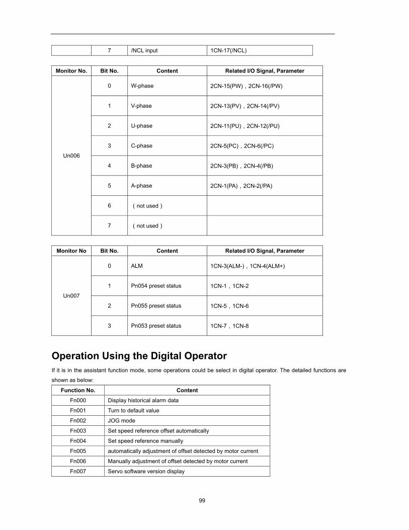
99
7 /NCL input 1CN-17(/NCL)
Monitor No. Bit No. Content Related I/O Signal, Parameter
Un006
0 W-phase 2CN-15(PW),2CN-16(/PW)
1 V-phase 2CN-13(PV),2CN-14(/PV)
2 U-phase 2CN-11(PU),2CN-12(/PU)
3 C-phase 2CN-5(PC),2CN-6(/PC)
4 B-phase 2CN-3(PB),2CN-4(/PB)
5 A-phase 2CN-1(PA),2CN-2(/PA)
6 (not used)
7 (not used)
Monitor No Bit No. Content Related I/O Signal, Parameter
Un007
0 ALM 1CN-3(ALM-),1CN-4(ALM+)
1 Pn054 preset status 1CN-1,1CN-2
2 Pn055 preset status 1CN-5,1CN-6
3 Pn053 preset status 1CN-7,1CN-8
Operation Using the Digital Operator If it is in the assistant function mode, some operations could be select in digital operator. The detailed functions are
shown as below:
Function No. Content
Fn000 Display historical alarm data
Fn001 Turn to default value
Fn002 JOG mode
Fn003 Set speed reference offset automatically
Fn004 Set speed reference manually
Fn005 automatically adjustment of offset detected by motor current
Fn006 Manually adjustment of offset detected by motor current
Fn007 Servo software version display
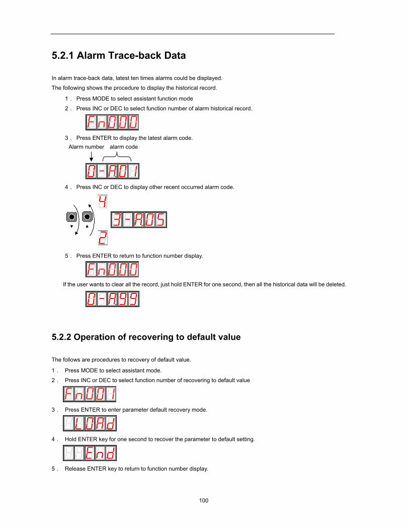
100
5.2.1 Alarm Trace-back Data
In alarm trace-back data, latest ten times alarms could be displayed.
The following shows the procedure to display the historical record.
1. Press MODE to select assistant function mode
2. Press INC or DEC to select function number of alarm historical record.
3. Press ENTER to display the latest alarm code. Alarm number alarm code
4. Press INC or DEC to display other recent occurred alarm code.
5. Press ENTER to return to function number display.
If the user wants to clear all the record, just hold ENTER for one second, then all the historical data will be deleted.
5.2.2 Operation of recovering to default value
The follows are procedures to recovery of default value.
1. Press MODE to select assistant mode.
2. Press INC or DEC to select function number of recovering to default value
3. Press ENTER to enter parameter default recovery mode.
4. Hold ENTER key for one second to recover the parameter to default setting.
5. Release ENTER key to return to function number display.
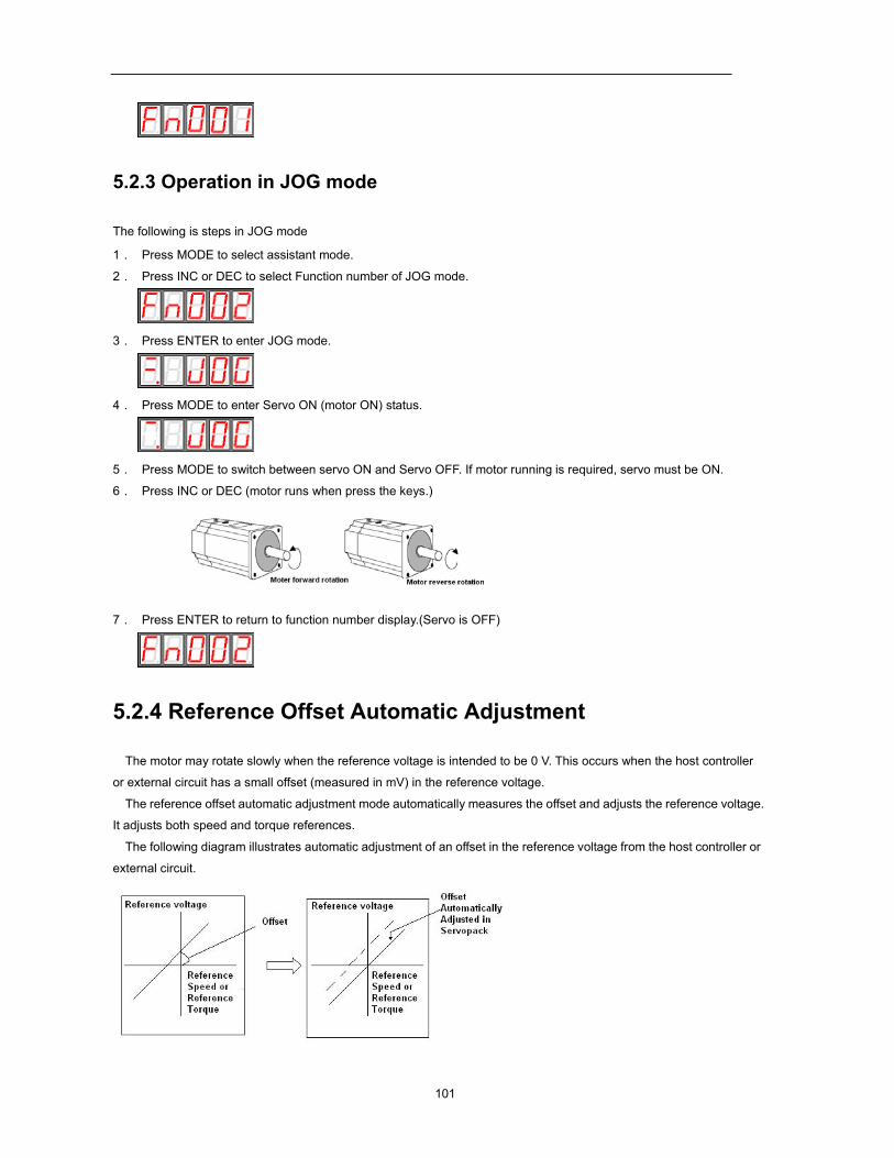
101
5.2.3 Operation in JOG mode
The following is steps in JOG mode
1. Press MODE to select assistant mode.
2. Press INC or DEC to select Function number of JOG mode.
3. Press ENTER to enter JOG mode.
4. Press MODE to enter Servo ON (motor ON) status.
5. Press MODE to switch between servo ON and Servo OFF. If motor running is required, servo must be ON.
6. Press INC or DEC (motor runs when press the keys.)
7. Press ENTER to return to function number display.(Servo is OFF)
5.2.4 Reference Offset Automatic Adjustment
The motor may rotate slowly when the reference voltage is intended to be 0 V. This occurs when the host controller
or external circuit has a small offset (measured in mV) in the reference voltage.
The reference offset automatic adjustment mode automatically measures the offset and adjusts the reference voltage.
It adjusts both speed and torque references.
The following diagram illustrates automatic adjustment of an offset in the reference voltage from the host controller or
external circuit.
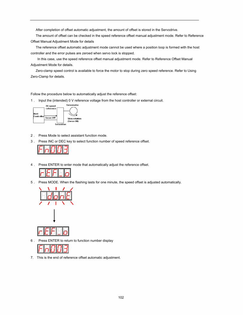
102
After completion of offset automatic adjustment, the amount of offset is stored in the Servodrive.
The amount of offset can be checked in the speed reference offset manual adjustment mode. Refer to Reference
Offset Manual Adjustment Mode for details
The reference offset automatic adjustment mode cannot be used where a position loop is formed with the host
controller and the error pulses are zeroed when servo lock is stopped.
In this case, use the speed reference offset manual adjustment mode. Refer to Reference Offset Manual
Adjustment Mode for details.
Zero-clamp speed control is available to force the motor to stop during zero speed reference. Refer to Using
Zero-Clamp for details.
Follow the procedure below to automatically adjust the reference offset:
1. Input the (intended) 0 V reference voltage from the host controller or external circuit.
2. Press Mode to select assistant function mode.
3. Press INC or DEC key to select function number of speed reference offset.
4. Press ENTER to enter mode that automatically adjust the reference offset.
5. Press MODE. When the flashing lasts for one minute, the speed offset is adjusted automatically.
6. Press ENTER to return to function number display
7. This is the end of reference offset automatic adjustment.
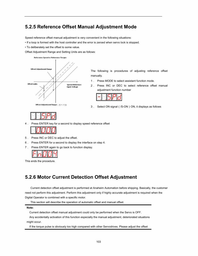
103
5.2.5 Reference Offset Manual Adjustment Mode
Speed reference offset manual adjustment is very convenient in the following situations:
• If a loop is formed with the host controller and the error is zeroed when servo lock is stopped.
• To deliberately set the offset to some value.
Offset Adjustment Range and Setting Units are as follows:
The following is procedures of adjusting reference offset
manually.
1. Press MODE to select assistant function mode.
2. Press INC or DEC to select reference offset manual adjustment function number
3. Select ON signal(/S-ON)ON, it displays as follows
4. Press ENTER key for a second to display speed reference offset
5. Press INC or DEC to adjust the offset.
6. Press ENTER for a second to display the interface on step 4.
7. Press ENTER again to go back to function display.
This ends the procedure.
5.2.6 Motor Current Detection Offset Adjustment
Current detection offset adjustment is performed at Anaheim Automation before shipping. Basically, the customer
need not perform this adjustment. Perform this adjustment only if highly accurate adjustment is required when the
Digital Operator is combined with a specific motor.
This section will describe the operation of automatic offset and manual offset.
Note: Current detection offset manual adjustment could only be performed when the Servo is OFF.
Any accidentally activation of this function especially the manual adjustment, deteriorated situations
might occur.
If the torque pulse is obviously too high compared with other Servodrives. Please adjust the offset
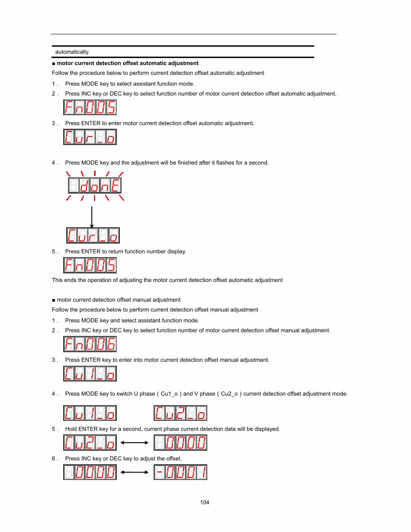
104
automatically.
motor current detection offset automatic adjustment
Follow the procedure below to perform current detection offset automatic adjustment
1. Press MODE key to select assistant function mode.
2. Press INC key or DEC key to select function number of motor current detection offset automatic adjustment.
3. Press ENTER to enter motor current detection offset automatic adjustment.
4. Press MODE key and the adjustment will be finished after it flashes for a second.
5. Press ENTER to return function number display.
This ends the operation of adjusting the motor current detection offset automatic adjustment
motor current detection offset manual adjustment
Follow the procedure below to perform current detection offset manual adjustment
1. Press MODE key and select assistant function mode.
2. Press INC key or DEC key to select function number of motor current detection offset manual adjustment.
3. Press ENTER key to enter into motor current detection offset manual adjustment.
4. Press MODE key to switch U phase(Cu1_o)and V phase(Cu2_o)current detection offset adjustment mode.
5. Hold ENTER key for a second, current phase current detection data will be displayed.
6. Press INC key or DEC key to adjust the offset.
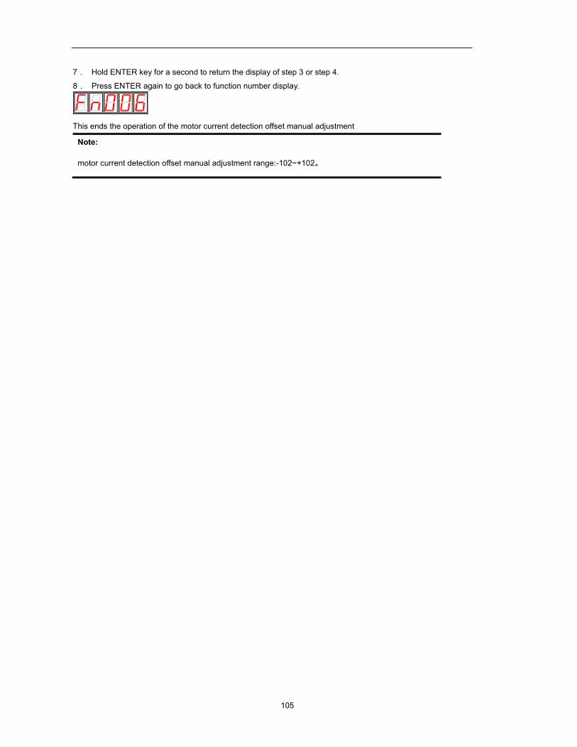
105
7. Hold ENTER key for a second to return the display of step 3 or step 4.
8. Press ENTER again to go back to function number display.
This ends the operation of the motor current detection offset manual adjustment
Note:
motor current detection offset manual adjustment range:-102~+102。
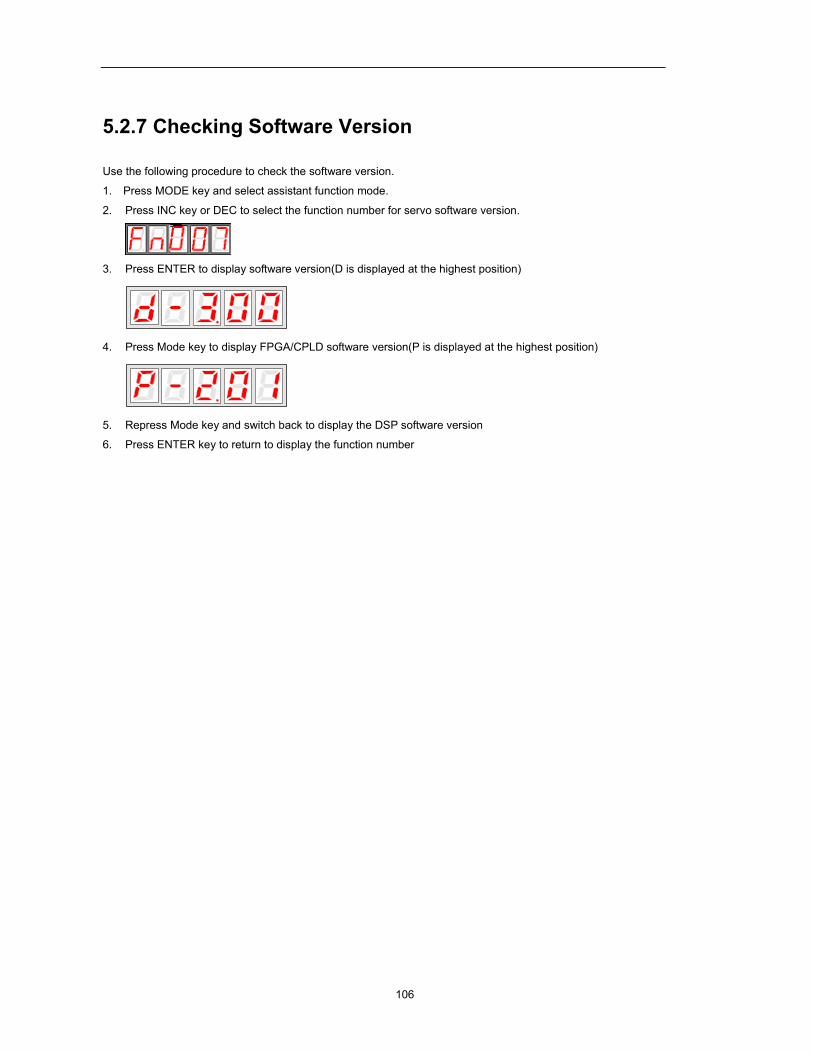
106
5.2.7 Checking Software Version
Use the following procedure to check the software version.
1. Press MODE key and select assistant function mode.
2. Press INC key or DEC to select the function number for servo software version.
3. Press ENTER to display software version(D is displayed at the highest position)
4. Press Mode key to display FPGA/CPLD software version(P is displayed at the highest position)
5. Repress Mode key and switch back to display the DSP software version
6. Press ENTER key to return to display the function number
107
Chapter 6
Communication functions
6.1 RS-485、RS-232、RS-422 Communication hardware
interface
EDB-A Servo drives have RS-485、RS-232、RS-422communication functions. With the help of these functions, it
can achieve reference modification and monitor servo drive status etc., However, RS-485,RS-232and RS-422 can not
be applied at the same time. It’s selective for RS-485/RS-232/RS-422 through the options of parameter Pn213. The
instruction as follows:
RS-232
It’s a must to use Anaheim Automation special RS232 cable of BST-CC24. Instructions:
The cable length is less than 15 meters when in a less disturbed environment. However, if transmission speed is
above 38.4Kbps, it’s strongly recommended that the cable length is less than 3 meters to ensure the accuracy of
transmission.
RS-485、RS422
Communication cable wring diagram:
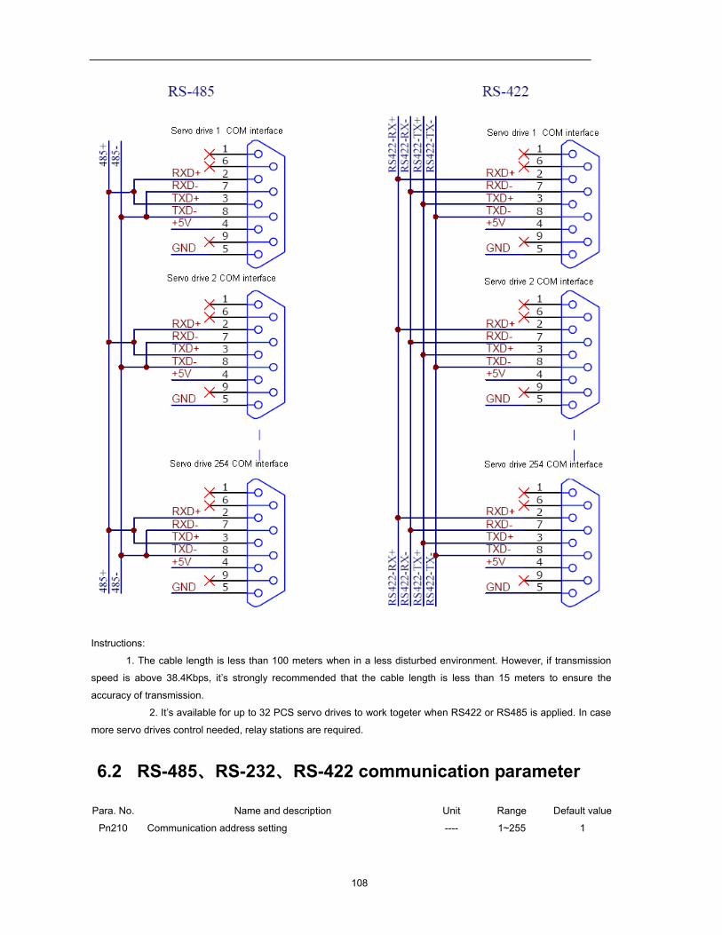
108
Instructions:
1. The cable length is less than 100 meters when in a less disturbed environment. However, if transmission
speed is above 38.4Kbps, it’s strongly recommended that the cable length is less than 15 meters to ensure the
accuracy of transmission.
2. It’s available for up to 32 PCS servo drives to work togeter when RS422 or RS485 is applied. In case
more servo drives control needed, relay stations are required.
6.2 RS-485、RS-232、RS-422 communication parameter
Para. No. Name and description Unit Range Default value
Pn210 Communication address setting ---- 1~255 1
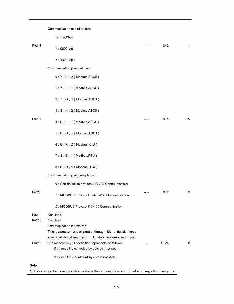
109
Pn211
Communication speed options:
0:4800bps
1:9600 bps
2:19200bps
---- 0~2 1
Pn212
Communication protocol form:
0:7,N,2(Modbus,ASCII)
1:7,E,1(Modbus,ASCII)
2:7,O,1(Modbus,ASCII)
3:8,N,2(Modbus,ASCII)
4:8,E,1(Modbus,ASCII)
5:8,O,1(Modbus,ASCII)
6:8,N,2(Modbus,RTU)
7:8,E,1(Modbus,RTU)
8:8,O,1(Modbus,RTU)
---- 0~8 5
Pn213
Communication protocol options:
0:Self-definition protocol RS-232 Communication
1:MODBUS Protocol RS-422/232 Communication
2:MODBUS Protocol RS-485 Communication
---- 0~2 2
Pn214 Not Used
Pn215 Not Used
Pn216
Communication bit control:
This parameter is designated through bit to decide input
source of digital input port. Bit0~bit7 represent input port
0~7 respectively. Bit definition represents as follows:
0 : input bit is controled by outside interface
1:input bit is controled by communication.
---- 0~255 0
Note: 1. After change the communication address through communication (that is to say, after change the
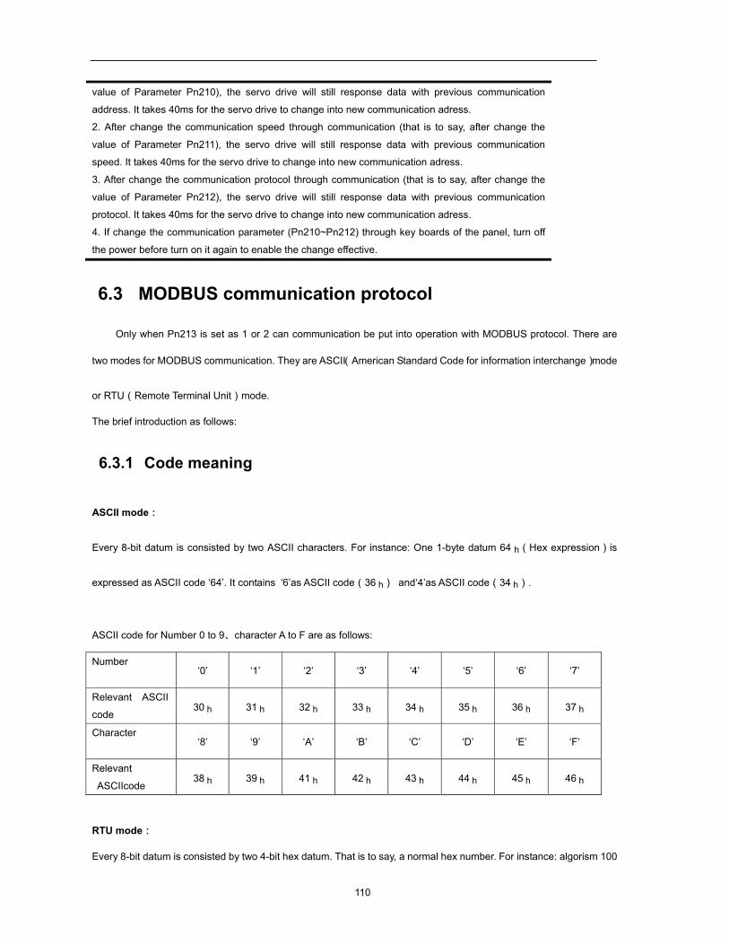
110
value of Parameter Pn210), the servo drive will still response data with previous communication
address. It takes 40ms for the servo drive to change into new communication adress.
2. After change the communication speed through communication (that is to say, after change the
value of Parameter Pn211), the servo drive will still response data with previous communication
speed. It takes 40ms for the servo drive to change into new communication adress.
3. After change the communication protocol through communication (that is to say, after change the
value of Parameter Pn212), the servo drive will still response data with previous communication
protocol. It takes 40ms for the servo drive to change into new communication adress.
4. If change the communication parameter (Pn210~Pn212) through key boards of the panel, turn off
the power before turn on it again to enable the change effective.
6.3 MODBUS communication protocol
Only when Pn213 is set as 1 or 2 can communication be put into operation with MODBUS protocol. There are
two modes for MODBUS communication. They are ASCII(American Standard Code for information interchange)mode
or RTU(Remote Terminal Unit)mode.
The brief introduction as follows:
6.3.1 Code meaning
ASCII mode:
Every 8-bit datum is consisted by two ASCII characters. For instance: One 1-byte datum 64 h(Hex expression)is
expressed as ASCII code ‘64’. It contains ‘6’as ASCII code(36 h) and‘4’as ASCII code(34 h).
ASCII code for Number 0 to 9、character A to F are as follows:
Number ‘0’ ‘1’ ‘2’ ‘3’ ‘4’ ‘5’ ‘6’ ‘7’
Relevant ASCII
code 30 h 31 h 32 h 33 h 34 h 35 h 36 h 37 h
Character ‘8’ ‘9’ ‘A’ ‘B’ ‘C’ ‘D’ ‘E’ ‘F’
Relevant
ASCIIcode 38 h 39 h 41 h 42 h 43 h 44 h 45 h 46 h
RTU mode:
Every 8-bit datum is consisted by two 4-bit hex datum. That is to say, a normal hex number. For instance: algorism 100
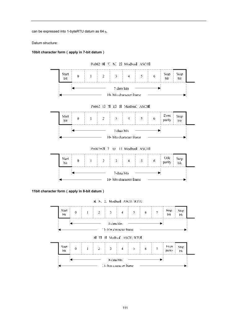
111
can be expressed into 1-byteRTU datum as 64 h.
Datum structure:
10bit character form(apply in 7-bit datum)
11bit character form(apply in 8-bit datum)
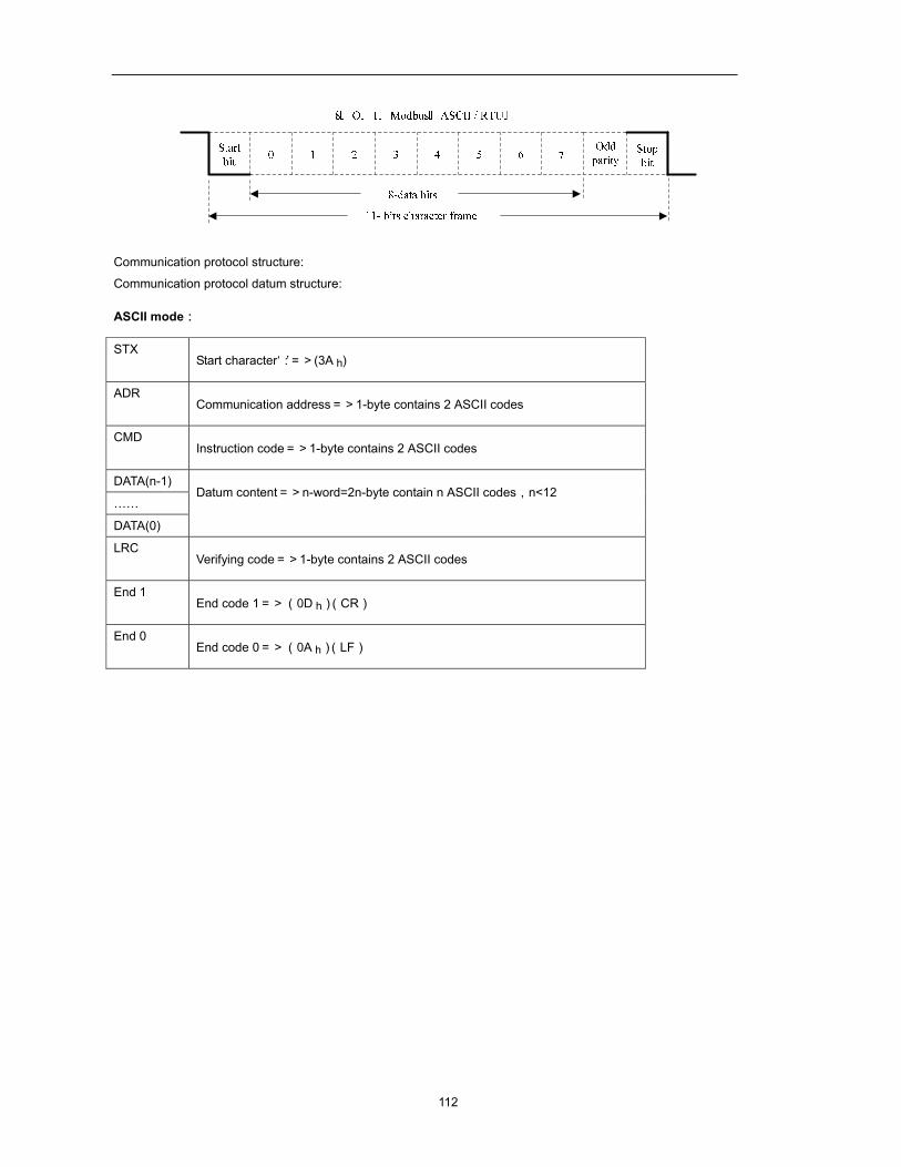
112
Communication protocol structure:
Communication protocol datum structure:
ASCII mode:
STX Start character‘:’=>(3A h)
ADR Communication address=>1-byte contains 2 ASCII codes
CMD Instruction code=>1-byte contains 2 ASCII codes
DATA(n-1) Datum content=>n-word=2n-byte contain n ASCII codes,n<12
……
DATA(0)
LRC Verifying code=>1-byte contains 2 ASCII codes
End 1 End code 1=>(0D h)(CR)
End 0 End code 0=>(0A h)(LF)
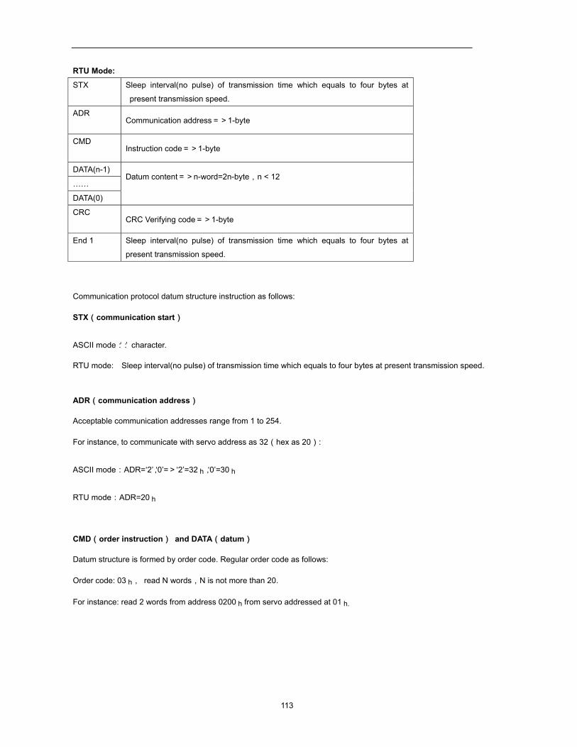
113
RTU Mode:
STX Sleep interval(no pulse) of transmission time which equals to four bytes at
present transmission speed.
ADR Communication address=>1-byte
CMD Instruction code=>1-byte
DATA(n-1) Datum content=>n-word=2n-byte,n < 12
……
DATA(0)
CRC CRC Verifying code=>1-byte
End 1 Sleep interval(no pulse) of transmission time which equals to four bytes at
present transmission speed.
Communication protocol datum structure instruction as follows:
STX(communication start)
ASCII mode:‘:’ character.
RTU mode: Sleep interval(no pulse) of transmission time which equals to four bytes at present transmission speed.
ADR(communication address)
Acceptable communication addresses range from 1 to 254.
For instance, to communicate with servo address as 32(hex as 20):
ASCII mode:ADR=‘2’,‘0’=>‘2’=32 h,‘0’=30 h
RTU mode:ADR=20 h
CMD(order instruction) and DATA(datum)
Datum structure is formed by order code. Regular order code as follows:
Order code: 03 h, read N words,N is not more than 20.
For instance: read 2 words from address 0200 h from servo addressed at 01 h.
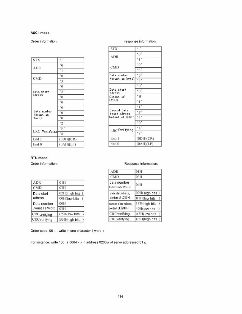
114
ASCII mode:
Order information: response information:
RTU mode: Order information: Response information:
Order code: 06 h,write in one character(word)
For instance: write 100 (0064 h)in address 0200 h of servo addressed 01 h.
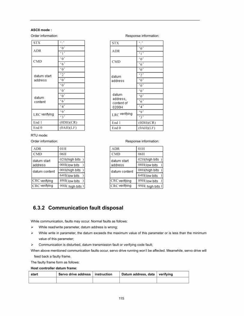
115
ASCII mode : Order information: Response information:
RTU mode:
Order information: Response information:
6.3.2 Communication fault disposal
While communication, faults may occur. Normal faults as follows:
While read/write parameter, datum address is wrong;
While write in parameter, the datum exceeds the maximum value of this parameter or is less than the minimum
value of this parameter;
Communication is disturbed, datum transmission fault or verifying code fault;
When above mentioned communication faults occur, servo drive running won’t be affected. Meanwhile, servo drive will
feed back a faulty frame.
The faulty frame form as follows:
Host controller datum frame:
start Servo drive address instruction Datum address, data verifying
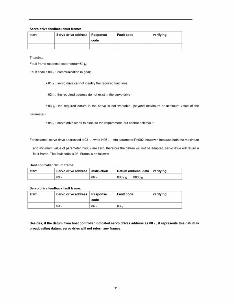
116
Servo drive feedback fault frame:
start Servo drive address Response
code
Fault code verifying
Thereinto:
Fault frame response code=order+80 h;
Fault code=00 h:communication in gear;
=01 h:servo drive cannot identify the required functions;
=02 h:the required address do not exist in the servo drive;
=03 h:the required datum in the servo is not workable. (beyond maximum or minimum value of the
parameter);
=04 h:servo drive starts to execute the requirement, but cannot achieve it;
For instance: servo drive addressed at03 h,write in06 h into parameter Pn002, however, because both the maximum
and minimum value of parameter Pn002 are zero, therefore the datum will not be adapted, servo drive will return a
fault frame. The fault code is 03. Frame is as follows:
Host controller datum frame:
start Servo drive address instruction Datum address, data verifying
03 h 06 h 0002 h 0006 h
Servo drive feedback fault frame:
start Servo drive address Response code
Fault code verifying
03 h 86 h 03 h
Besides, if the datum from host controller indicated servo drives address as 00 h , it represents this datum is broadcasting datum, servo dries will not return any frames.
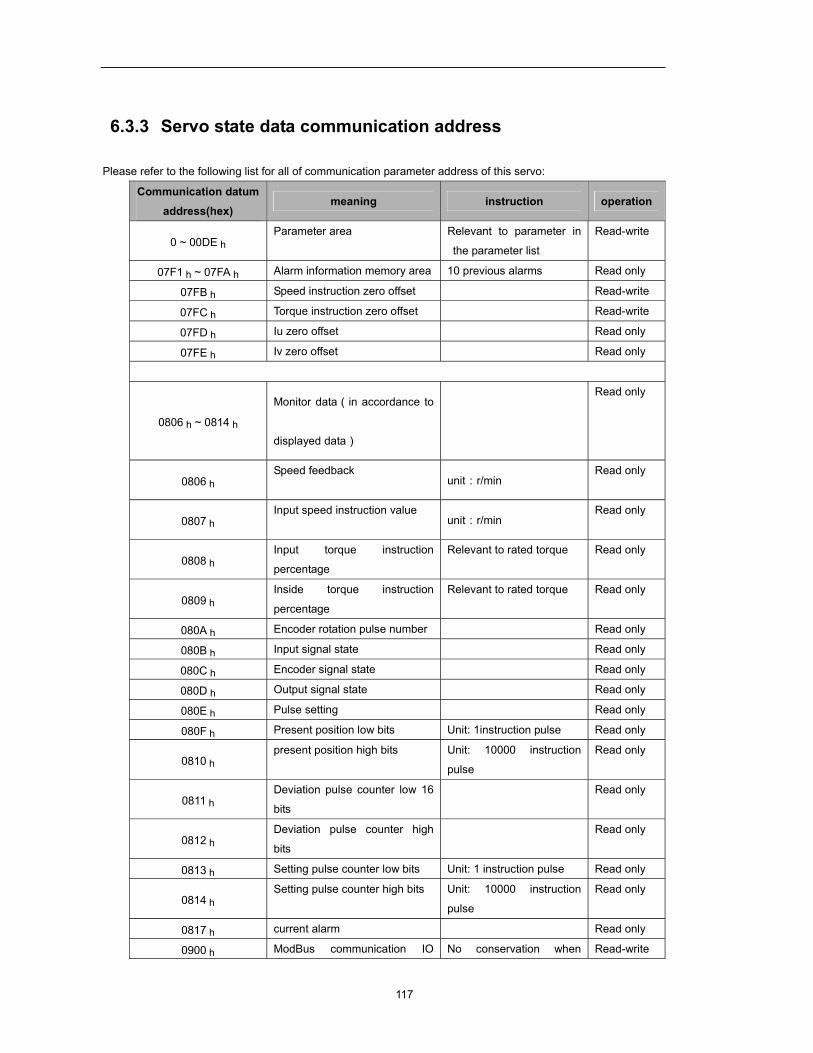
117
6.3.3 Servo state data communication address
Please refer to the following list for all of communication parameter address of this servo:
Communication datum address(hex)
meaning instruction operation
0 ~ 00DE h Parameter area Relevant to parameter in
the parameter list
Read-write
07F1 h ~ 07FA h Alarm information memory area 10 previous alarms Read only
07FB h Speed instruction zero offset Read-write
07FC h Torque instruction zero offset Read-write
07FD h Iu zero offset Read only
07FE h Iv zero offset Read only
0806 h ~ 0814 h
Monitor data(in accordance to
displayed data)
Read only
0806 h Speed feedback
unit:r/min Read only
0807 h Input speed instruction value
unit:r/min Read only
0808 h Input torque instruction
percentage
Relevant to rated torque Read only
0809 h Inside torque instruction
percentage
Relevant to rated torque Read only
080A h Encoder rotation pulse number Read only
080B h Input signal state Read only
080C h Encoder signal state Read only
080D h Output signal state Read only
080E h Pulse setting Read only
080F h Present position low bits Unit: 1instruction pulse Read only
0810 h present position high bits Unit: 10000 instruction
pulse
Read only
0811 h Deviation pulse counter low 16
bits
Read only
0812 h Deviation pulse counter high
bits
Read only
0813 h Setting pulse counter low bits Unit: 1 instruction pulse Read only
0814 h Setting pulse counter high bits Unit: 10000 instruction
pulse
Read only
0817 h current alarm Read only
0900 h ModBus communication IO No conservation when Read-write
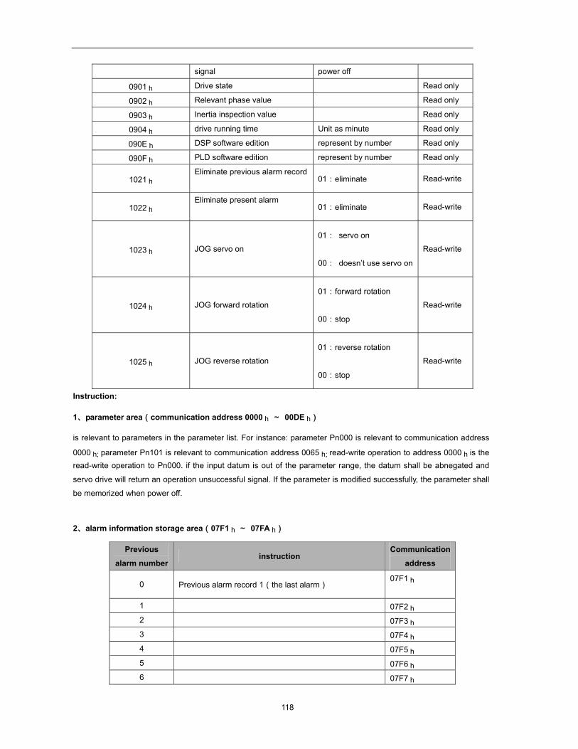
118
signal power off
0901 h Drive state Read only
0902 h Relevant phase value Read only
0903 h Inertia inspection value Read only
0904 h drive running time Unit as minute Read only
090E h DSP software edition represent by number Read only
090F h PLD software edition represent by number Read only
1021 h Eliminate previous alarm record
01:eliminate Read-write
1022 h Eliminate present alarm
01:eliminate Read-write
1023 h JOG servo on
01: servo on
00: doesn’t use servo on
Read-write
1024 h JOG forward rotation
01:forward rotation
00:stop
Read-write
1025 h JOG reverse rotation
01:reverse rotation
00:stop
Read-write
Instruction:
1、parameter area(communication address 0000 h ~ 00DE h)
is relevant to parameters in the parameter list. For instance: parameter Pn000 is relevant to communication address
0000 h; parameter Pn101 is relevant to communication address 0065 h; read-write operation to address 0000 h is the read-write operation to Pn000. if the input datum is out of the parameter range, the datum shall be abnegated and
servo drive will return an operation unsuccessful signal. If the parameter is modified successfully, the parameter shall
be memorized when power off.
2、alarm information storage area(07F1 h ~ 07FA h)
Previous
alarm number instruction
Communication
address
0 Previous alarm record 1(the last alarm) 07F1 h
1 07F2 h
2 07F3 h 3 07F4 h 4 07F5 h
5 07F6 h 6 07F7 h
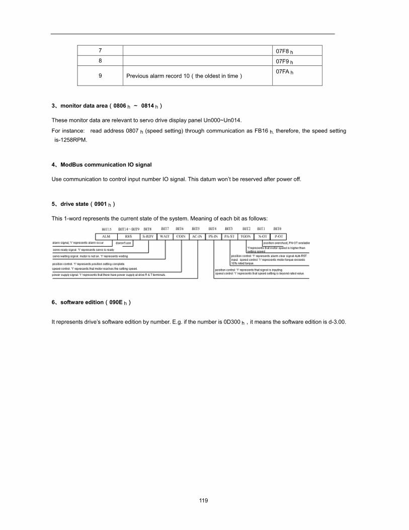
119
7 07F8 h
8 07F9 h
9 Previous alarm record 10(the oldest in time) 07FA h
3、monitor data area(0806 h ~ 0814 h)
These monitor data are relevant to servo drive display panel Un000~Un014.
For instance: read address 0807 h (speed setting) through communication as FB16 h. therefore, the speed setting is-1258RPM.
4、ModBus communication IO signal
Use communication to control input number IO signal. This datum won’t be reserved after power off.
5、drive state(0901 h)
This 1-word represents the current state of the system. Meaning of each bit as follows:
6、software edition(090E h)
It represents drive’s software edition by number. E.g. if the number is 0D300 h,it means the software edition is d-3.00.
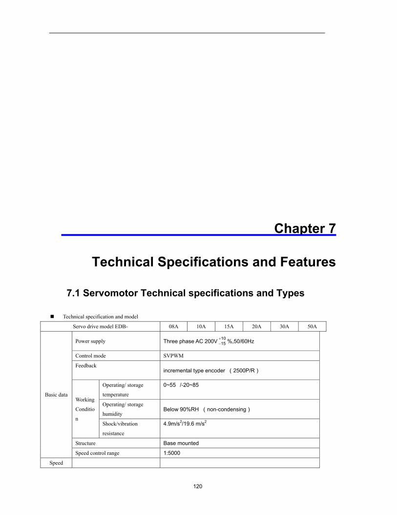
120
Chapter 7
Technical Specifications and Features
7.1 Servomotor Technical specifications and Types
Technical specification and model
Servo drive model EDB- 08A 10A 15A 20A 30A 50A
Basic data
Power supply Three phase AC 200V 1015+− %,50/60Hz
Control mode SVPWM
Feedback incremental type encoder (2500P/R)
Working
Conditio
n
Operating/ storage
temperature
0~55/-20~85
Operating/ storage
humidity Below 90%RH (non-condensing)
Shock/vibration
resistance
4.9m/s2/19.6 m/s2
Structure Base mounted
Speed control range 1:5000
Speed
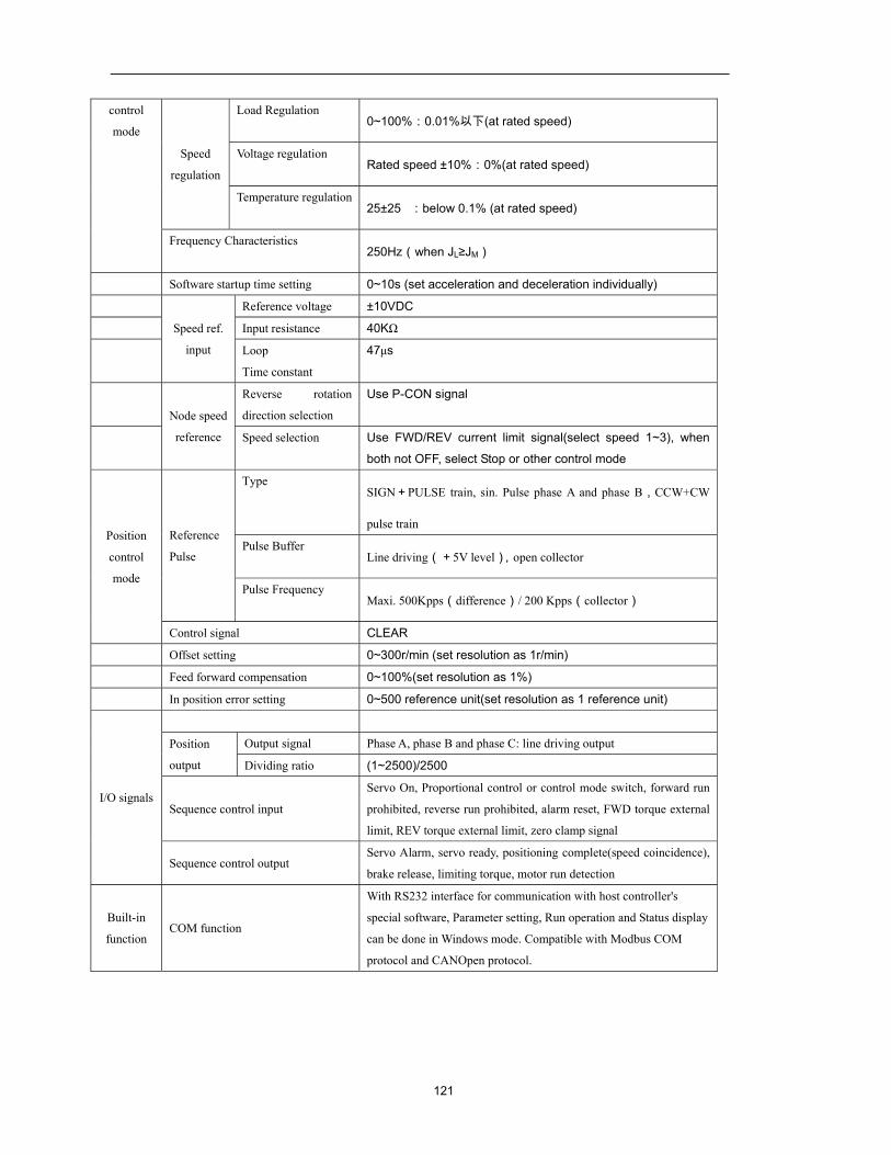
121
control
mode
Speed
regulation
Load Regulation 0~100%:0.01%以下(at rated speed)
Voltage regulation Rated speed ±10%:0%(at rated speed)
Temperature regulation 25±25:below 0.1% (at rated speed)
Frequency Characteristics 250Hz(when JL≥JM)
Software startup time setting 0~10s (set acceleration and deceleration individually)
Speed ref.
input
Reference voltage ±10VDC
Input resistance 40KΩ
Loop
Time constant
47μs
Node speed
reference
Reverse rotation
direction selection
Use P-CON signal
Speed selection Use FWD/REV current limit signal(select speed 1~3), when
both not OFF, select Stop or other control mode
Position
control
mode
Reference
Pulse
Type SIGN+PULSE train, sin. Pulse phase A and phase B,CCW+CW
pulse train
Pulse Buffer Line driving(+5V level),open collector
Pulse Frequency Maxi. 500Kpps(difference)/ 200 Kpps(collector)
Control signal CLEAR
Offset setting 0~300r/min (set resolution as 1r/min)
Feed forward compensation 0~100%(set resolution as 1%)
In position error setting 0~500 reference unit(set resolution as 1 reference unit)
I/O signals
Position
output
Output signal Phase A, phase B and phase C: line driving output
Dividing ratio (1~2500)/2500
Sequence control input
Servo On, Proportional control or control mode switch, forward run
prohibited, reverse run prohibited, alarm reset, FWD torque external
limit, REV torque external limit, zero clamp signal
Sequence control output Servo Alarm, servo ready, positioning complete(speed coincidence),
brake release, limiting torque, motor run detection
Built-in
function COM function
With RS232 interface for communication with host controller's
special software, Parameter setting, Run operation and Status display
can be done in Windows mode. Compatible with Modbus COM
protocol and CANOpen protocol.
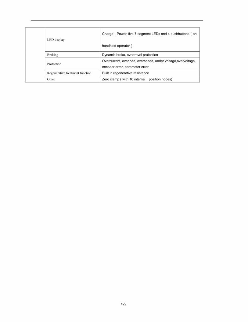
122
LED display
Charge,Power, five 7-segment LEDs and 4 pushbuttons(on
handheld operator)
Braking Dynamic brake, overtravel protection
Protection Overcurrent, overload, overspeed, under voltage,overvoltage,
encoder error, parameter error
Regenerative treatment function Built in regenerative resistance
Other Zero clamp ( with 16 internal position nodes)
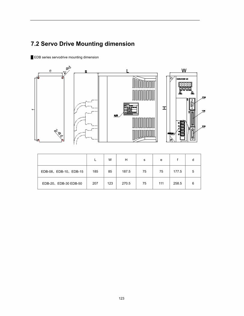
123
7.2 Servo Drive Mounting dimension
EDB series servodrive mounting dimension
L W H s e f d
EDB-08、EDB-10、EDB-15 185 85 187.5 75 75 177.5 5
EDB-20、EDB-30 EDB-50 207 123 270.5 75 111 258.5 6
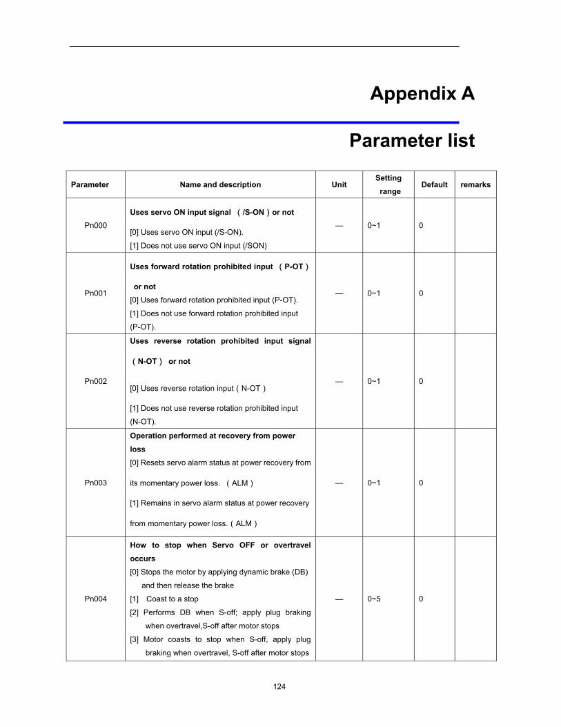
124
Appendix A
Parameter list
Parameter Name and description Unit Setting range
Default remarks
Pn000
Uses servo ON input signal (/S-ON)or not
[0] Uses servo ON input (/S-ON).
[1] Does not use servo ON input (/SON)
— 0~1 0
Pn001
Uses forward rotation prohibited input (P-OT)
or not [0] Uses forward rotation prohibited input (P-OT).
[1] Does not use forward rotation prohibited input
(P-OT).
— 0~1 0
Pn002
Uses reverse rotation prohibited input signal
(N-OT) or not
[0] Uses reverse rotation input(N-OT)
[1] Does not use reverse rotation prohibited input
(N-OT).
— 0~1 0
Pn003
Operation performed at recovery from power
loss [0] Resets servo alarm status at power recovery from
its momentary power loss. (ALM)
[1] Remains in servo alarm status at power recovery
from momentary power loss.(ALM)
— 0~1 0
Pn004
How to stop when Servo OFF or overtravel occurs [0] Stops the motor by applying dynamic brake (DB)
and then release the brake
[1] Coast to a stop
[2] Performs DB when S-off; apply plug braking
when overtravel,S-off after motor stops
[3] Motor coasts to stop when S-off, apply plug
braking when overtravel, S-off after motor stops
— 0~5 0
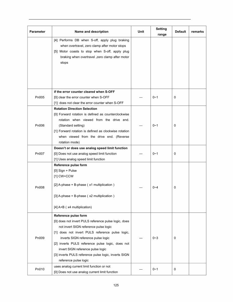
125
Parameter Name and description Unit Setting range
Default remarks
[4] Performs DB when S-off, apply plug braking
when overtravel, zero clamp after motor stops
[5] Motor coasts to stop when S-off, apply plug
braking when overtravel ,zero clamp after motor
stops
Pn005
if the error counter cleared when S-OFF [0] clear the error counter when S-OFF
[1]: does not clear the error counter when S-OFF
— 0~1 0
Pn006
Rotation Direction Selection [0] Forward rotation is defined as counterclockwise
rotation when viewed from the drive end.
(Standard setting)
[1] Forward rotation is defined as clockwise rotation
when viewed from the drive end. (Reverse
rotation mode)
— 0~1 0
Pn007
Doesn’t or does use analog speed limit function [0] Does not use analog speed limit function
[1] Uses analog speed limit function
— 0~1 0
Pn008
Reference pulse form [0] Sign + Pulse
[1] CW+CCW
[2] A-phase + B-phase(x1 multiplication)
[3] A-phase + B-phase(x2 multiplication)
[4] A+B(x4 multiplication)
— 0~4 0
Pn009
Reference pulse form [0] does not invert PULS reference pulse logic, does
not invert SIGN reference pulse logic
[1] does not invert PULS reference pulse logic,
inverts SIGN reference pulse logic
[2] inverts PULS reference pulse logic, does not
invert SIGN reference pulse logic
[3] inverts PULS reference pulse logic, inverts SIGN
reference pulse logic
— 0~3 0
Pn010 uses analog current limit function or not
[0] Does not use analog current limit function — 0~1 0
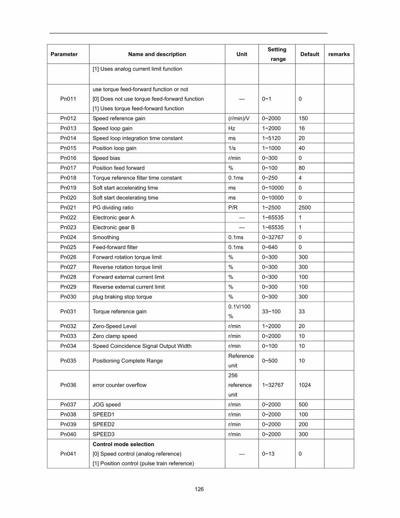
126
Parameter Name and description Unit Setting range
Default remarks
[1] Uses analog current limit function
Pn011
use torque feed-forward function or not
[0] Does not use torque feed-forward function
[1] Uses torque feed-forward function
— 0~1 0
Pn012 Speed reference gain (r/min)/V 0~2000 150
Pn013 Speed loop gain Hz 1~2000 16
Pn014 Speed loop integration time constant ms 1~5120 20
Pn015 Position loop gain 1/s 1~1000 40
Pn016 Speed bias r/min 0~300 0
Pn017 Position feed forward % 0~100 80
Pn018 Torque reference filter time constant 0.1ms 0~250 4
Pn019 Soft start accelerating time ms 0~10000 0
Pn020 Soft start decelerating time ms 0~10000 0
Pn021 PG dividing ratio P/R 1~2500 2500
Pn022 Electronic gear A — 1~65535 1
Pn023 Electronic gear B — 1~65535 1
Pn024 Smoothing 0.1ms 0~32767 0
Pn025 Feed-forward filter 0.1ms 0~640 0
Pn026 Forward rotation torque limit % 0~300 300
Pn027 Reverse rotation torque limit % 0~300 300
Pn028 Forward external current limit % 0~300 100
Pn029 Reverse external current limit % 0~300 100
Pn030 plug braking stop torque % 0~300 300
Pn031 Torque reference gain 0.1V/100
% 33~100 33
Pn032 Zero-Speed Level r/min 1~2000 20
Pn033 Zero clamp speed r/min 0~2000 10
Pn034 Speed Coincidence Signal Output Width r/min 0~100 10
Pn035 Positioning Complete Range Reference
unit 0~500 10
Pn036 error counter overflow
256
reference
unit
1~32767 1024
Pn037 JOG speed r/min 0~2000 500
Pn038 SPEED1 r/min 0~2000 100
Pn039 SPEED2 r/min 0~2000 200
Pn040 SPEED3 r/min 0~2000 300
Pn041
Control mode selection [0] Speed control (analog reference)
[1] Position control (pulse train reference)
— 0~13 0
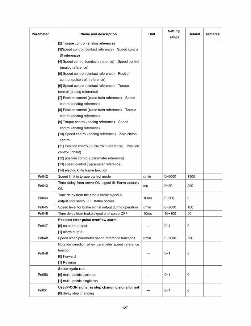
127
Parameter Name and description Unit Setting range
Default remarks
[2] Torque control (analog reference)
[3]Speed control (contact reference) Speed control
(0 reference)
[4] Speed control (contact reference) Speed control
(analog reference)
[5] Speed control (contact reference) Position
control (pulse train reference)
[6] Speed control (contact reference) Torque
control (analog reference)
[7] Position control (pulse train reference) Speed
control (analog reference)
[8] Position control (pulse train reference) Torque
control (analog reference)
[9] Torque control (analog reference) Speed
control (analog reference)
[10] Speed control (analog reference) Zero clamp
control
[11] Position control (pulse train reference) Position
control (inhibit)
[12] position control ( parameter reference)
[13] speed control ( parameter reference)
[14] electric knife frame function
Pn042 Speed limit in torque control mode r/min 0~6000 1500
Pn043 Time delay from servo ON signal till Servo actually
ON ms 0~20 200
Pn044 Time delay from the time a brake signal is
output until servo OFF status occurs 10ms 0~500 0
Pn045 Speed level for brake signal output during operation r/min 0~2000 100
Pn046 Time delay from brake signal until servo OFF 10ms 10~100 50
Pn047
Position error pulse overflow alarm [0] no alarm output
[1] alarm output
- 0~1 0
Pn048 Speed when parameter speed reference functions r/min 0~2000 500
Pn049
Rotation direction when parameter speed reference
function
[0] Forward
[1] Reverse
— 0~1 0
Pn050
Select cycle run [0] multi- points cycle run
[1] multi- points single run
— 0~1 0
Pn051 Use /P-CON signal as step changing signal or not [0] delay step changing
— 0~1 0
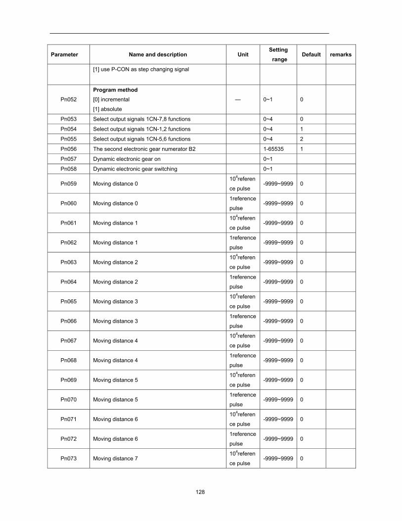
128
Parameter Name and description Unit Setting range
Default remarks
[1] use P-CON as step changing signal
Pn052
Program method [0] incremental
[1] absolute
— 0~1 0
Pn053 Select output signals 1CN-7,8 functions 0~4 0
Pn054 Select output signals 1CN-1,2 functions 0~4 1
Pn055 Select output signals 1CN-5,6 functions 0~4 2
Pn056 The second electronic gear numerator B2 1-65535 1
Pn057 Dynamic electronic gear on 0~1
Pn058 Dynamic electronic gear switching 0~1
Pn059 Moving distance 0 104referen
ce pulse -9999~9999 0
Pn060 Moving distance 0 1reference
pulse -9999~9999 0
Pn061 Moving distance 1 104referen
ce pulse -9999~9999 0
Pn062 Moving distance 1 1reference
pulse -9999~9999 0
Pn063 Moving distance 2 104referen
ce pulse -9999~9999 0
Pn064 Moving distance 2 1reference
pulse -9999~9999 0
Pn065 Moving distance 3 104referen
ce pulse -9999~9999 0
Pn066 Moving distance 3 1reference
pulse -9999~9999 0
Pn067 Moving distance 4 104referen
ce pulse -9999~9999 0
Pn068 Moving distance 4 1reference
pulse -9999~9999 0
Pn069 Moving distance 5 104referen
ce pulse -9999~9999 0
Pn070 Moving distance 5 1reference
pulse -9999~9999 0
Pn071 Moving distance 6 104referen
ce pulse -9999~9999 0
Pn072 Moving distance 6 1reference
pulse -9999~9999 0
Pn073 Moving distance 7 104referen
ce pulse -9999~9999 0
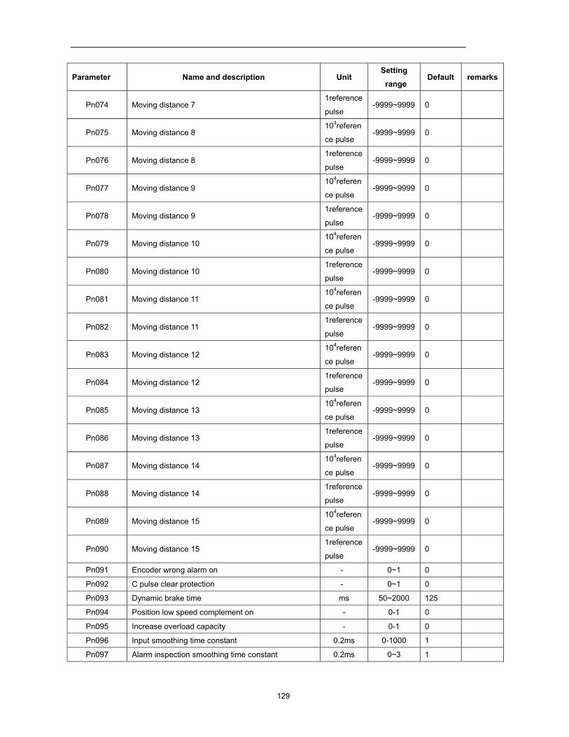
129
Parameter Name and description Unit Setting range
Default remarks
Pn074 Moving distance 7 1reference
pulse -9999~9999 0
Pn075 Moving distance 8 104referen
ce pulse -9999~9999 0
Pn076 Moving distance 8 1reference
pulse -9999~9999 0
Pn077 Moving distance 9 104referen
ce pulse -9999~9999 0
Pn078 Moving distance 9 1reference
pulse -9999~9999 0
Pn079 Moving distance 10 104referen
ce pulse -9999~9999 0
Pn080 Moving distance 10 1reference
pulse -9999~9999 0
Pn081 Moving distance 11 104referen
ce pulse -9999~9999 0
Pn082 Moving distance 11 1reference
pulse -9999~9999 0
Pn083 Moving distance 12 104referen
ce pulse -9999~9999 0
Pn084 Moving distance 12 1reference
pulse -9999~9999 0
Pn085 Moving distance 13 104referen
ce pulse -9999~9999 0
Pn086 Moving distance 13 1reference
pulse -9999~9999 0
Pn087 Moving distance 14 104referen
ce pulse -9999~9999 0
Pn088 Moving distance 14 1reference
pulse -9999~9999 0
Pn089 Moving distance 15 104referen
ce pulse -9999~9999 0
Pn090 Moving distance 15 1reference
pulse -9999~9999 0
Pn091 Encoder wrong alarm on - 0~1 0
Pn092 C pulse clear protection - 0~1 0
Pn093 Dynamic brake time ms 50~2000 125
Pn094 Position low speed complement on - 0-1 0
Pn095 Increase overload capacity - 0-1 0
Pn096 Input smoothing time constant 0.2ms 0-1000 1
Pn097 Alarm inspection smoothing time constant 0.2ms 0~3 1
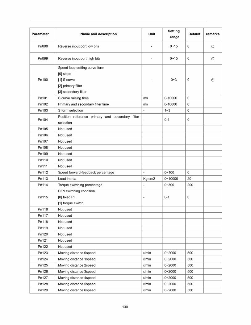
130
Parameter Name and description Unit Setting range
Default remarks
Pn098 Reverse input port low bits - 0~15 0 ①
Pn099 Reverse input port high bits - 0~15 0 ①
Pn100
Speed loop setting curve form
[0] slope
[1] S curve
[2] primary filter
[3] secondary filter
- 0~3 0 ①
Pn101 S curve raising time ms 0-10000 0
Pn102 Primary and secondary filter time ms 0-10000 0
Pn103 S form selection - 1~3 0
Pn104 Position reference primary and secondary filter
selection - 0-1 0
Pn105 Not used
Pn106 Not used
Pn107 Not used
Pn108 Not used
Pn109 Not used
Pn110 Not used
Pn111 Not used
Pn112 Speed forward-feedback percentage - 0~100 0
Pn113 Load inertia Kg.cm2 0~10000 20
Pn114 Torque switching percentage - 0~300 200
Pn115
P/PI switching condition
[0] fixed PI
[1] torque switch
- 0-1 0
Pn116 Not used
Pn117 Not used
Pn118 Not used
Pn119 Not used
Pn120 Not used
Pn121 Not used
Pn122 Not used
Pn123 Moving distance 0speed r/min 0~2000 500
Pn124 Moving distance 1speed r/min 0~2000 500
Pn125 Moving distance 2speed r/min 0~2000 500
Pn126 Moving distance 3speed r/min 0~2000 500
Pn127 Moving distance 4speed r/min 0~2000 500
Pn128 Moving distance 5speed r/min 0~2000 500
Pn129 Moving distance 6speed r/min 0~2000 500
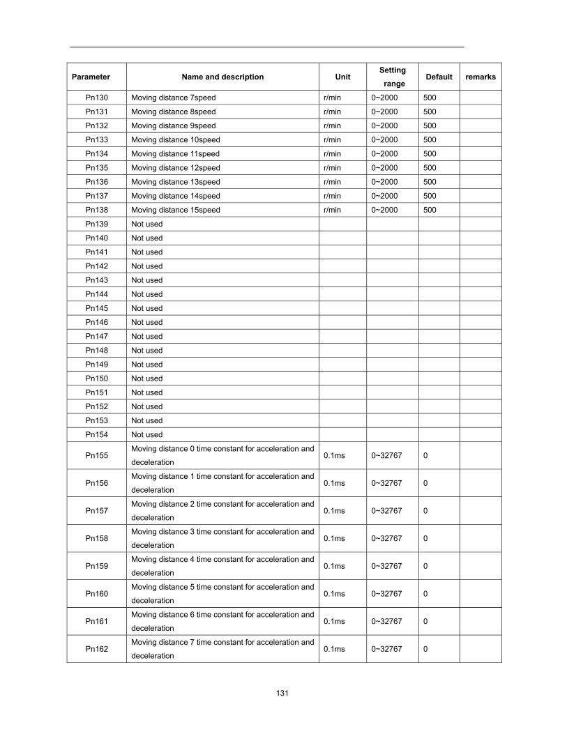
131
Parameter Name and description Unit Setting range
Default remarks
Pn130 Moving distance 7speed r/min 0~2000 500
Pn131 Moving distance 8speed r/min 0~2000 500
Pn132 Moving distance 9speed r/min 0~2000 500
Pn133 Moving distance 10speed r/min 0~2000 500
Pn134 Moving distance 11speed r/min 0~2000 500
Pn135 Moving distance 12speed r/min 0~2000 500
Pn136 Moving distance 13speed r/min 0~2000 500
Pn137 Moving distance 14speed r/min 0~2000 500
Pn138 Moving distance 15speed r/min 0~2000 500
Pn139 Not used
Pn140 Not used
Pn141 Not used
Pn142 Not used
Pn143 Not used
Pn144 Not used
Pn145 Not used
Pn146 Not used
Pn147 Not used
Pn148 Not used
Pn149 Not used
Pn150 Not used
Pn151 Not used
Pn152 Not used
Pn153 Not used
Pn154 Not used
Pn155 Moving distance 0 time constant for acceleration and
deceleration 0.1ms 0~32767 0
Pn156 Moving distance 1 time constant for acceleration and
deceleration 0.1ms 0~32767 0
Pn157 Moving distance 2 time constant for acceleration and
deceleration 0.1ms 0~32767 0
Pn158 Moving distance 3 time constant for acceleration and
deceleration 0.1ms 0~32767 0
Pn159 Moving distance 4 time constant for acceleration and
deceleration 0.1ms 0~32767 0
Pn160 Moving distance 5 time constant for acceleration and
deceleration 0.1ms 0~32767 0
Pn161 Moving distance 6 time constant for acceleration and
deceleration 0.1ms 0~32767 0
Pn162 Moving distance 7 time constant for acceleration and
deceleration 0.1ms 0~32767 0
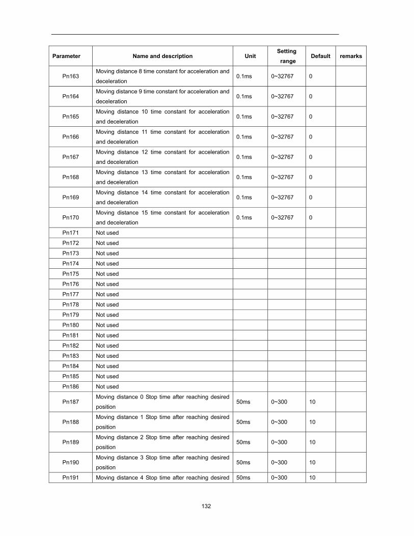
132
Parameter Name and description Unit Setting range
Default remarks
Pn163 Moving distance 8 time constant for acceleration and
deceleration 0.1ms 0~32767 0
Pn164 Moving distance 9 time constant for acceleration and
deceleration 0.1ms 0~32767 0
Pn165 Moving distance 10 time constant for acceleration
and deceleration 0.1ms 0~32767 0
Pn166 Moving distance 11 time constant for acceleration
and deceleration 0.1ms 0~32767 0
Pn167 Moving distance 12 time constant for acceleration
and deceleration 0.1ms 0~32767 0
Pn168 Moving distance 13 time constant for acceleration
and deceleration 0.1ms 0~32767 0
Pn169 Moving distance 14 time constant for acceleration
and deceleration 0.1ms 0~32767 0
Pn170 Moving distance 15 time constant for acceleration
and deceleration 0.1ms 0~32767 0
Pn171 Not used
Pn172 Not used
Pn173 Not used
Pn174 Not used
Pn175 Not used
Pn176 Not used
Pn177 Not used
Pn178 Not used
Pn179 Not used
Pn180 Not used
Pn181 Not used
Pn182 Not used
Pn183 Not used
Pn184 Not used
Pn185 Not used
Pn186 Not used
Pn187 Moving distance 0 Stop time after reaching desired
position 50ms 0~300 10
Pn188 Moving distance 1 Stop time after reaching desired
position 50ms 0~300 10
Pn189 Moving distance 2 Stop time after reaching desired
position 50ms 0~300 10
Pn190 Moving distance 3 Stop time after reaching desired
position 50ms 0~300 10
Pn191 Moving distance 4 Stop time after reaching desired 50ms 0~300 10
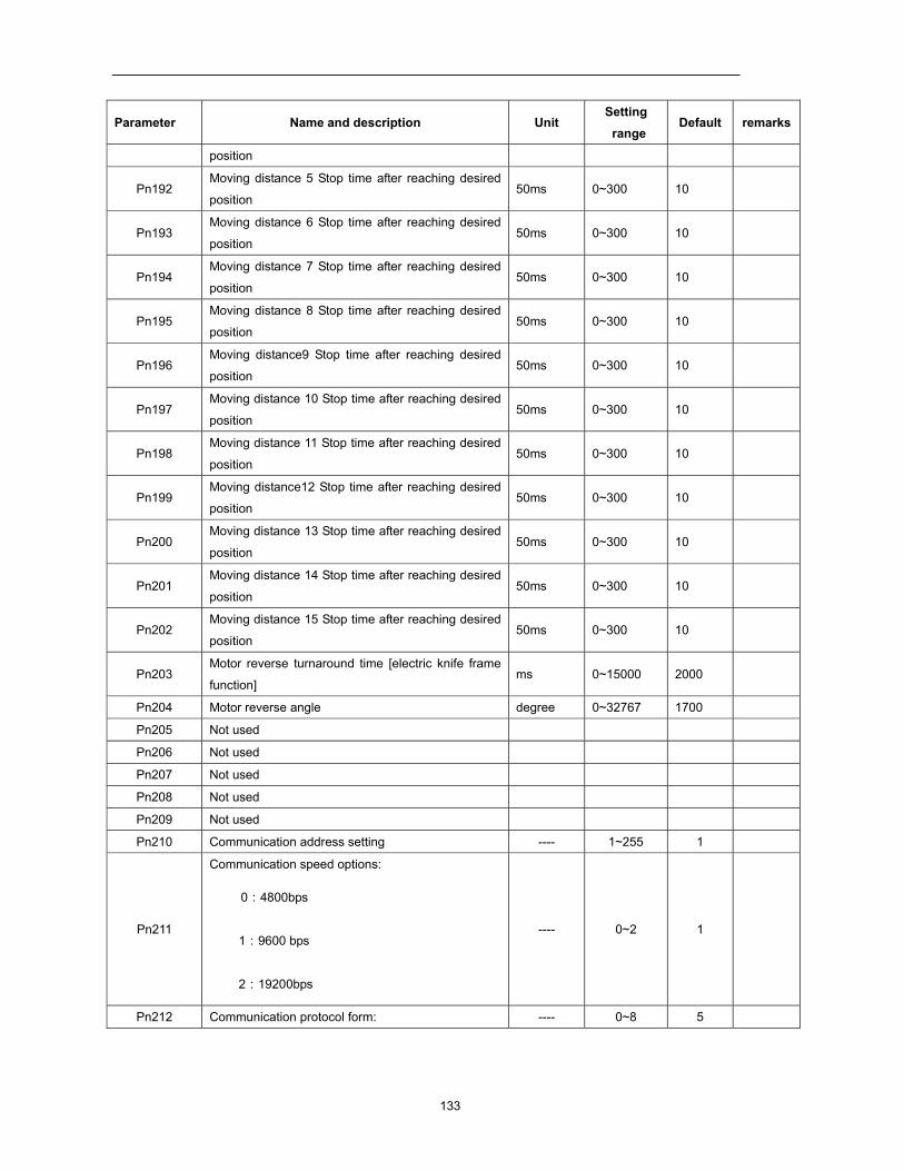
133
Parameter Name and description Unit Setting range
Default remarks
position
Pn192 Moving distance 5 Stop time after reaching desired
position 50ms 0~300 10
Pn193 Moving distance 6 Stop time after reaching desired
position 50ms 0~300 10
Pn194 Moving distance 7 Stop time after reaching desired
position 50ms 0~300 10
Pn195 Moving distance 8 Stop time after reaching desired
position 50ms 0~300 10
Pn196 Moving distance9 Stop time after reaching desired
position 50ms 0~300 10
Pn197 Moving distance 10 Stop time after reaching desired
position 50ms 0~300 10
Pn198 Moving distance 11 Stop time after reaching desired
position 50ms 0~300 10
Pn199 Moving distance12 Stop time after reaching desired
position 50ms 0~300 10
Pn200 Moving distance 13 Stop time after reaching desired
position 50ms 0~300 10
Pn201 Moving distance 14 Stop time after reaching desired
position 50ms 0~300 10
Pn202 Moving distance 15 Stop time after reaching desired
position 50ms 0~300 10
Pn203 Motor reverse turnaround time [electric knife frame
function] ms 0~15000 2000
Pn204 Motor reverse angle degree 0~32767 1700
Pn205 Not used
Pn206 Not used
Pn207 Not used
Pn208 Not used
Pn209 Not used
Pn210 Communication address setting ---- 1~255 1
Pn211
Communication speed options:
0:4800bps
1:9600 bps
2:19200bps
---- 0~2 1
Pn212 Communication protocol form: ---- 0~8 5
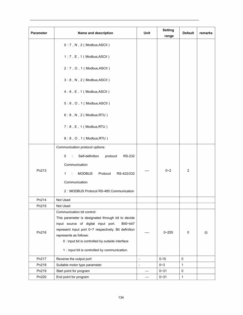
134
Parameter Name and description Unit Setting range
Default remarks
0:7,N,2(Modbus,ASCII)
1:7,E,1(Modbus,ASCII)
2:7,O,1(Modbus,ASCII)
3:8,N,2(Modbus,ASCII)
4:8,E,1(Modbus,ASCII)
5:8,O,1(Modbus,ASCII)
6:8,N,2(Modbus,RTU)
7:8,E,1(Modbus,RTU)
8:8,O,1(Modbus,RTU)
Pn213
Communication protocol options:
0 : Self-definition protocol RS-232
Communication
1 : MODBUS Protocol RS-422/232
Communication
2:MODBUS Protocol RS-485 Communication
---- 0~2 2
Pn214 Not Used
Pn215 Not Used
Pn216
Communication bit control:
This parameter is designated through bit to decide
input source of digital input port. Bit0~bit7
represent input port 0~7 respectively. Bit definition
represents as follows:
0 : input bit is controlled by outside interface
1:input bit is controlled by communication.
---- 0~255 0 ④
Pn217 Reverse the output port - 0-15 0
Pn218 Suitable motor type parameter - 0~3 1
Pn219 Start point for program — 0~31 0
Pn220 End point for program — 0~31 1
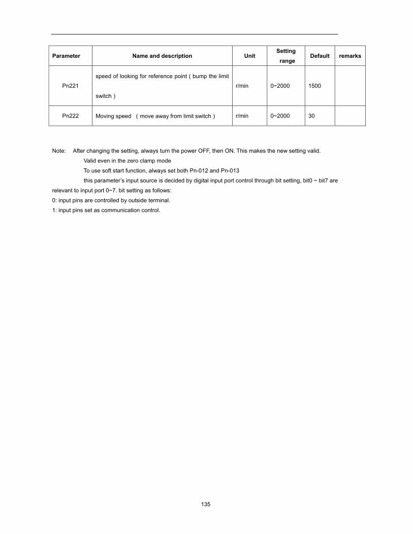
135
Parameter Name and description Unit Setting range
Default remarks
Pn221
speed of looking for reference point(bump the limit
switch)
r/min 0~2000 1500
Pn222 Moving speed (move away from limit switch) r/min 0~2000 30
Note: After changing the setting, always turn the power OFF, then ON. This makes the new setting valid. Valid even in the zero clamp mode
To use soft start function, always set both Pn-012 and Pn-013
this parameter’s input source is decided by digital input port control through bit setting, bit0 ~ bit7 are
relevant to input port 0~7. bit setting as follows:
0: input pins are controlled by outside terminal.
1: input pins set as communication control.
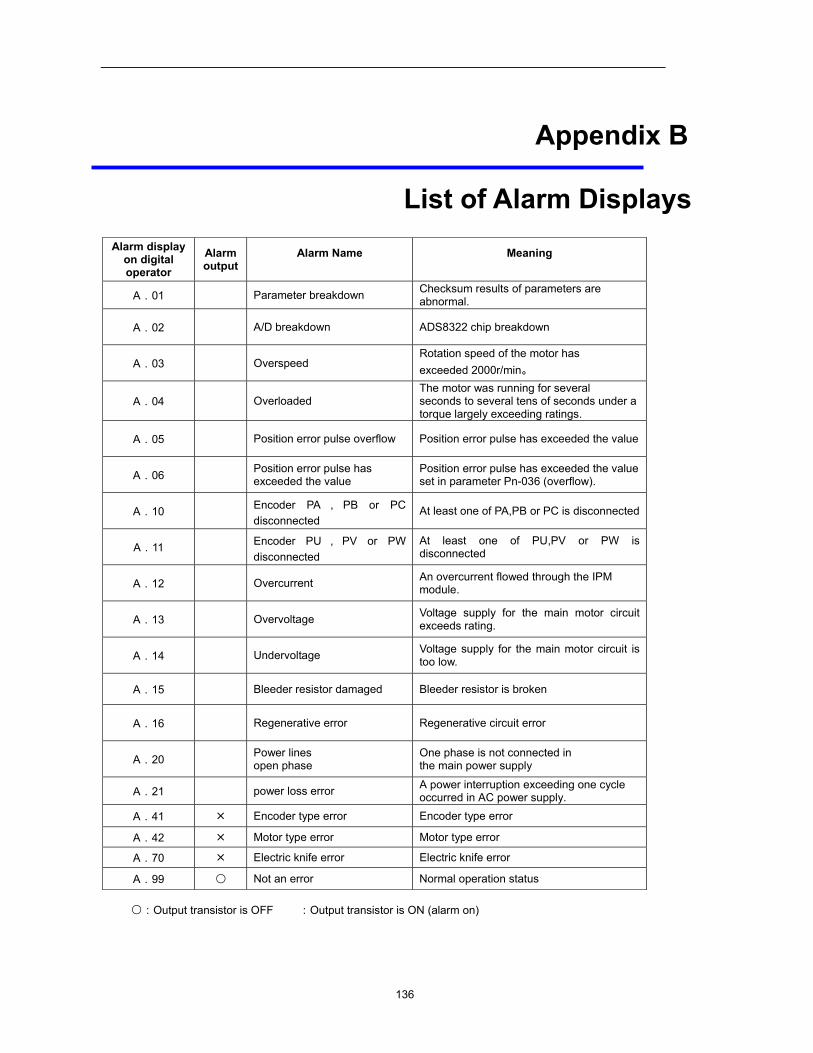
136
Appendix B
List of Alarm Displays
Alarm display on digital operator
Alarm output
Alarm Name
Meaning
A.01 Parameter breakdown Checksum results of parameters are abnormal.
A.02 A/D breakdown ADS8322 chip breakdown
A.03 Overspeed Rotation speed of the motor has exceeded 2000r/min。
A.04 Overloaded The motor was running for several seconds to several tens of seconds under a torque largely exceeding ratings.
A.05 Position error pulse overflow Position error pulse has exceeded the value
A.06 Position error pulse has exceeded the value
Position error pulse has exceeded the value set in parameter Pn-036 (overflow).
A.10 Encoder PA , PB or PC disconnected
At least one of PA,PB or PC is disconnected
A.11 Encoder PU , PV or PW disconnected
At least one of PU,PV or PW is disconnected
A.12 Overcurrent An overcurrent flowed through the IPM module.
A.13 Overvoltage Voltage supply for the main motor circuit exceeds rating.
A.14 Undervoltage Voltage supply for the main motor circuit is too low.
A.15 Bleeder resistor damaged Bleeder resistor is broken
A.16 Regenerative error Regenerative circuit error
A.20 Power lines open phase
One phase is not connected in the main power supply
A.21 power loss error A power interruption exceeding one cycle occurred in AC power supply.
A.41 Encoder type error Encoder type error
A.42 Motor type error Motor type error
A.70 Electric knife error Electric knife error
A.99 〇 Not an error Normal operation status
〇:Output transistor is OFF :Output transistor is ON (alarm on)