estimating soil hydraulic parameters from transient … · estimating soil hydraulic parameters...
TRANSCRIPT

Estimating soil hydraulic parameters from transient flow
experiments in a centrifuge using parameter optimization
technique
Jirka Simunek
Department of Environmental Sciences, University of California, Riverside, California, USA
John R. Nimmo
U.S. Geological Survey, Menlo Park, California, USA
Received 28 May 2004; revised 20 January 2005; accepted 7 February 2005; published 27 April 2005.
[1] A modified version of the Hydrus software package that can directly or inverselysimulate water flow in a transient centrifugal field is presented. The inverse solver forparameter estimation of the soil hydraulic parameters is then applied to multirotationtransient flow experiments in a centrifuge. Using time-variable water contents measured ata sequence of several rotation speeds, soil hydraulic properties were successfullyestimated by numerical inversion of transient experiments. The inverse method was thenevaluated by comparing estimated soil hydraulic properties with those determinedindependently using an equilibrium analysis. The optimized soil hydraulic propertiescompared well with those determined using equilibrium analysis and steady stateexperiment. Multirotation experiments in a centrifuge not only offer significant timesavings by accelerating time but also provide significantly more information for theparameter estimation procedure compared to multistep outflow experiments in agravitational field.
Citation: Simunek, J., and J. R. Nimmo (2005), Estimating soil hydraulic parameters from transient flow experiments in a centrifuge
using parameter optimization technique, Water Resour. Res., 41, W04015, doi:10.1029/2004WR003379.
1. Introduction
[2] The main information needed for evaluating, analyz-ing, and predicting flow and solute transport in soilsconcerns the soil hydraulic properties. Traditional methodsof measuring soil hydraulic properties are tedious and timeconsuming [Dane and Topp, 2002]; therefore faster, easiertechniques are constantly being sought [e.g., Hopmans etal., 2002]. One way of accelerating the measurementprocess is by carrying out needed experiments in a centri-fuge. The steady state conditions required for many types ofmeasurements can be achieved in much shorter time [e.g.,Nimmo et al., 1987, 2002; Nimmo and Mello, 1991; Concaand Wright, 1992].[3] Over the last century, high-speed centrifuges have
become standard in scientific and technical fields of soilphysics, petroleum industry and environmental engineeringfor measuring water contents, and saturated and unsaturatedhydraulic conductivities. Briggs and McLane [1907] used acentrifuge to measure what they called the ‘‘moisture equiv-alent,’’ a single-number index of a soil’s capacity to retainwater. Later, the water retention curve was the measurementobjective, for example, in the work of Gardner [1937],Russell and Richards [1938], and Hassler and Brunner[1945]. In these methods the water in an unsaturated sampleequilibrates with the centrifugal field, much as in thehanging-column method [Dane and Hopmans, 2002] it
equilibrates with a gravitational field. Development of suchtechniques has continued to the present [Forbes, 1994;Paningbatan, 1980; Sigda and Wilson, 2003]. The use ofcentrifuge-scaled physical modeling of dynamic unsaturatedflow has also been explored recently [e.g., Culligan et al.,1997; Nakajima et al., 2003]. For measuring unsaturatedhydraulic conductivity by the steady state centrifuge method,two different types of apparatus have been used, as explainedby Nimmo et al. [2002]. In the internal flow control (IFC)apparatus the means of controlling flow is internal tothe centrifuge bucket [Nimmo et al., 1987], while in theunsaturated flow apparatus (UFA), the flow is controlledoutside the centrifuge [Conca and Wright, 1992, 1998]. Eachof these implementations has its own advantages anddisadvantages, for example larger samples and greaterspeeds with the IFC apparatus, faster operation and lessdemand on the operator with the UFA apparatus [Nimmo etal., 2002]. Some experiments have investigated transientinstead of steady flow [e.g., Alemi et al., 1976; Nimmo,1990], and even unstable flow [Culligan et al., 1997;Griffioen et al., 1997]. So far these transient methodshave not led to widely used techniques for soil propertymeasurement, though they provide significant insights intothe nature of unsaturated flow.[4] Recent advances allow measurement of state variables
inside the rotating sample.Nimmo [1990] measured electricalconductivity using a four-electrode technique and convertedthe measured values into water contents. Savvidou andCulligan [1998] monitored pore pressures and solute con-centrations in a spinning sample with miniature pressure
Copyright 2005 by the American Geophysical Union.0043-1397/05/2004WR003379$09.00
W04015
WATER RESOURCES RESEARCH, VOL. 41, W04015, doi:10.1029/2004WR003379, 2005
1 of 9

transducers and resistivity probes. Investigators at the IdahoNational Engineering and Environmental Laboratory areexperimenting with measuring pressure heads usingminiature tensiometers rotating together with soil samples[Mattson et al., 2003].[5] Direct solvers of the Richards equation modified to
account for a centrifugal field have been developed in thelast two decades. Bear et al. [1984] presented a theory offluid flow through a deformable porous medium in thepresence of a centrifugal force and then solved the resultingflow and deformation equations using the finite differencemethod. They discussed implementation of several types ofboundary conditions for different applications and presentedcalculated water content and pressure head profiles forhypothetical simulations. In their simulations they showedthat the porosity changes were less than 0.01% after12 minutes of centrifuging, and thus can be neglected inmajority of applications. Nimmo [1990] also developed adirect solver of the Richards equation for a centrifugalfield and successfully compared numerical simulationsusing independently determined soil hydraulic propertiesto measured results of transient flow experiments.[6] An alternative to steady state experiments is analysis
of transient experiments using parameter estimation tech-niques [Hopmans et al., 2002]. Steady state calculations areoften based on assumption of constant water contents andzero, or linear, pressure head gradients, which is not alwaysthe case. On the other hand, parameter estimation tech-niques, such as those based on the numerical solution of theRichards equation, do not require such assumptions, and areconstrained only by assumptions inherent in the derivationof the transient Richards equation. The one-step outflowmethod [Gardner, 1956; Kool et al., 1985] and themultistep outflow method [van Dam et al., 1994; Echingand Hopmans, 1993; Durner et al., 1999] are frequentlyused in combination with a parameter estimation techniqueto determine soil hydraulic parameters in a gravitational field[Hopmans et al., 2002]. During the experiment, pressures orsuctions are applied at the top or bottom of the soil samplewhile the resulting outflow from the sample, and, optionally,also the pressure head within the sample, are measured.Cumulative outflow data in combination with measuredpressure heads, if available, are then used to define theobjective function against which the numerical model iscalibrated to estimate soil hydraulic parameters.[7] Similar procedures can be followed in the centrifuge
using step changes in rotational speed rather than appliedpressure head. Different rotation speeds then, when thelower boundary condition is specified by the zero pressurelevel at an imposed water table established within a porousplate below the soil boundary, will result in differentsuctions applied at the bottom of the sample. Similarly tothe multistep outflow experiment in a gravitational field,sequentially increasing rotational speeds will result instepwise draining of the sample. This information can beused to define the objective function for model calibration.Alemi et al. [1976] presented a theory for analyzing thevolumetric outflow of water from a soil core when the speedof centrifugation is suddenly increased. Their approach,however, was not based on numerical inversion of theRichards equation, and they did not present or analyzeexperimental data.
[8] When a multistep outflow experiment in a gravita-tional field is carried out for a long enough time at eachpressure step to reach steady conditions, the resulting pairsof water contents and pressure heads define data points ofthe retention curve. Similar experiments in a centrifugalfield can provide much more information. Since a centrif-ugal field results in pressure heads that vary greatly betweenthe top and bottom of the sample, each steady statecondition can provide multiple data points of the retentioncurve depending on the number of positions at which thewater content is measured.[9] In this manuscript we address the question of whether
one can obtain additional benefits by combining theadvantages of centrifuge-accelerated experiments withparameter estimation analysis. The objectives of this paperare threefold. The first is to present direct and inversesolvers of the Richards equation modified for a transientcentrifugal field. Second, to apply the inverse solver forparameter estimation of the soil hydraulic parameters usingmultirotation transient flow experiments in a centrifuge.Third, to evaluate the method by comparing estimated soilhydraulic properties with those determined independentlyusing an equilibrium analysis.
2. Theory
2.1. Mathematical Model
[10] Darcy-Buckingham’s law for one-dimensional flowin a centrifugal field, neglecting gravity and hysteresis, canbe expressed as [Nimmo et al., 1987; Conca and Wright,1992]
q ¼ �K* yð Þ dydr
� rw2r
� �ð1Þ
where q is the Darcy flux [LT�1], y is the matric potential[ML�1 T�2, Pa], r is the bulk density of water [ML�3], w isthe angular speed [radT�1], K* is the hydraulic conductivity[L3TM�1], and r is the radial coordinate [L]. Thisformulation leads to units for the hydraulic conductivitythat are not often used. Simple transformation of theequation leads to conductivity being expressed in morecommonly used units of [LT�1] and Darcy-Buckingham’slaw being expressed in terms of the pressure head:
q ¼ �K*rgdyrgdr
� rw2r
rg
� �¼ �K
dh
dr� w2r
g
� �ð2Þ
where K(=K*rg) is the hydraulic conductivity in [LT�1], gis the gravitational acceleration [LT�2] (i.e., 9.81 m s�2) andh is the pressure head [L].[11] While the Richards equation in a unit gravitational
field has the following formulation
@q@t
¼ @
@xK
@h
@xþ cosa
� �� �ð3Þ
where q is the water content [L3 L�3], and a is the anglebetween gravity and flow direction (0� for vertical flow), the
2 of 9
W04015 SIMUNEK AND NIMMO: TRANSIENT ANALYSES OF FLOW EXPERIMENTS IN A CENTRIFUGE W04015

modified version of the Richards equation for a centrifugalfield is:
@q@t
¼ @
@rK
@h
@r� w2r
g
� �� �ð4Þ
2.2. Numerical Model
[12] The numerical model for flow in a centrifugal fieldwas developed by modifying the Hydrus-1d code [Simuneket al., 1998b]. The Richards equation (3) in Hydrus issolved numerically using a Galerkin type linear finiteelement method combined with a mass lumping scheme,leading to a numerical scheme equivalent to standard finitedifferences. Integration in time is achieved using an implicit(backward) finite difference scheme for both saturated andunsaturated conditions. The water content term is evaluatedusing the mass conservative method proposed by Celia etal. [1990] that leads to the set of nonlinear algebraicequations:
q jþ1;kþ1i � q j
i
Dt¼ 1
DxK
jþ1;kiþ1=2
hjþ1;kþ1iþ1 � h
jþ1;kþ1i
Dxi
� K
jþ1;ki�1=2
hjþ1;kþ1i � h
jþ1;kþ1i�1
Dxi�1
!
þK
jþ1;kiþ1=2 � K
jþ1;ki�1=2
Dxcosa ð5Þ
After taking into account initial and boundary conditions,these are solved using the Picard iteration scheme. In (5), iis the node number in the spatial discretization, j is the indexfor the temporal discretization, k is the iteration number inthe Picard iteration scheme, Dt is the time step [T], and Dx[=(xi+1 � xi�1)/2], Dxi [=xi+1 � xi], and Dxi�1 [=xi � xi�1]are spatial discretization steps [L].[13] The modified Richards equation for flow in a cen-
trifugal field (4) is discretized in a similar manner, leadingto
q jþ1;kþ1i � q j
i
Dt¼ 1
DrK
jþ1;kiþ1=2
hjþ1;kþ1iþ1 � h
jþ1;kþ1i
Dri
� K
jþ1;ki�1=2
hjþ1;kþ1i � h
jþ1;kþ1i�1
Dri�1
!
� w2
gK
jþ1;ki þ ri
Kjþ1;kiþ1=2 � K
jþ1;ki�1=2
Dr
!ð6Þ
where Dr [=(ri+1� ri�1)/2], Dri [=ri+1� ri], and Dri�1 [=ri�ri�1] are spatial discretization steps [L].[14] Numerical solution requires adaptive time steps
and spatially variable discretization. Discretization at theoutflow boundary needs to be significantly finer to accom-modate large gradients at early times after a change in therotation speed and to result in small mass balance errors.[15] Special attention needs to be paid to flux boundary
conditions, since they have an important effect on stabilityof the numerical solution, as well as on the overall massbalance error. The upper boundary condition was specifiedby discretization of the Richards equation as follows:
q jþ1;kþ1N � q j
N
Dt¼ 2
DrN�1
�qjþ1N � K
jþ1;kN�1=2
hjþ1;kþ1N � h
jþ1;kþ1N�1
DrN�1
þKjþ1;kN�1=2
w2rN�1=2
g
!ð7Þ
while the lower boundary condition discretized Darcy’s law:
q1 ¼ �Kdh
dr� w2r
g
� �� �K
jþ1;k1þ1=2
hjþ1;kþ12 � h
jþ1;kþ11
Dr�w2r1þ1=2
g
!
ð8Þ
where qN and q1 are the specified upper and lower boundaryfluxes [LT�1] and indices N and 1 represent boundarynodes.
2.3. Soil Hydraulic Properties
[16] The unsaturated soil hydraulic properties in thispaper are assumed to be represented by the followingexpressions [van Genuchten, 1980]:
Se hð Þ ¼ q hð Þ � qrqs � qr
¼ 1
1þ ahj jnð Þmð9Þ
K qð Þ ¼ KsSle 1� 1� S1=me
� �mh i2ð10Þ
where Se is the effective water content (dimensionless), Ks isthe saturated hydraulic conductivity [LT�1], qr and qs denoteresidual and saturated water contents [L3 L�3], respectively,l is a pore connectivity parameter (dimensionless), and a[L�1], n (dimensionless), and m(=1 � 1/n) (dimensionless)are empirical parameters. The predictive K(q) model isbased on the capillary model of Mualem [1976] inconjunction with equation (9). The pore connectivityparameter l in the hydraulic conductivity function wasestimated by Mualem [1976] to be 0.5 as an average formany soils. The hydraulic characteristics defined byequations (9) and (10) contain 5 unknown parameters: qr,qs, a, n, and Ks. For a multirotation experiment carried out asa drying process, the hydraulic parameters in Equations (9)and (10) represent drying branches of the unsaturatedhydraulic properties.
2.4. Parameter Optimization
[17] The soil hydraulic parameters of (9) and (10) areobtained by calibrating the numerical model by minimizingthe objective function F defined as the sum of squareddeviations between measured and calculated water contents:
F b; qð Þ ¼Xmj¼1
Xnji¼1
qj* tið Þ � qj ti; bð Þ� 2 ð11Þ
where m represents different locations of water contentmeasurements, nj is the number of measurements at aparticular location, qj*(ti) are specific water content mea-surements at time ti and location j, and qj(ti, b) are thecorresponding model predictions for the vector of optimizedparameters b (e.g., qr, qs, a, n, and Ks).[18] Minimization of the objective function F is accom-
plished by using the Levenberg-Marquardt nonlinear min-imization method [Marquardt, 1963], which has become acommonly used approach in nonlinear least squares fittingamong soil scientists and hydrologists [Simunek andHopmans, 2002]. The method combines the Newton andsteepest descend methods, and provides confidence inter-vals for the optimized parameters. Since the Levenberg-
W04015 SIMUNEK AND NIMMO: TRANSIENT ANALYSES OF FLOW EXPERIMENTS IN A CENTRIFUGE
3 of 9
W04015

Marquardt method is a gradient method that seeks only thelocal minimum, we restarted each optimization with severaldifferent initial estimates of optimized parameters, andreport here those that resulted in the lowest value of theobjective function.[19] Although in the presented analyses we assume
that measured water contents are point measurements, thenumerical code can also consider a finite measurementvolume by averaging calculated water contents overspecified volume. While in this paper we define the objec-tive function only in terms of the water content, the Hydrusmodel allows other types of information, such as pressureheads and actual or cumulative outflow, to be considered aswell.
3. Materials, Methods, and Data
[20] Details about the centrifuge apparatus, as well asabout the soil sample used in this study are given by Nimmo[1990]. Here we only summarize the main features ofcompleted experiments and their corresponding analyses.The centrifuge was specially modified by the manufacturer,Beckman Instruments, to incorporate a Meridian LaboratoryMM12 high-speed, low-noise rotating electrical contractoron top of the rotor. (Brand names are given for identificationonly and do not indicate any endorsement by UCR orUSGS.) The soil sample was placed in a retainer on aporous ceramic plate 9.2 mm thick (Figure 1). The effectivehydraulic conductivity of a plate was measured to be 3 �10�7 m s�1 [Nimmo, 1990]. A short lip of the imperviousplate supporting the ceramic plate maintained a water table
near the bottom of the ceramic plate (away from the axis ofrotation). For different rotation speeds the water table at thisposition established different constant pressure heads at theoutflow boundary of the soil sample.[21] Eight electrodes in two vertical rows were installed
through the retainer into the soil sample. This configurationallowed electrical conductivity measurements usingsix different four-electrode sets (Figure 1). Three mainmeasurements were obtained by using four neighboringelectrodes (small square configuration), and thus electrodes 1,2, 3, and 4 composed the lower electrode set (measure-ments I); 3, 4, 5, and 6 the middle set (measurements II);and 5, 6, 7, and 8 the upper set (measurements III). Threeother combinations of electrodes (larger rectangle configu-ration) could also be analyzed, resulting in measurementsets IV (electrodes 1, 2, 5, and 6), V (electrodes 3, 4, 7, and8), and VI (electrodes 1, 2, 7, and 8). Electrical conductivityobservations are thus at mean depths of 2.67, 1.905, 1.141,2.279, 1.520, 1.905 cm for measurement sets I through VI.Nimmo [1990] conducted supplementary measurementsshowing that about 90% of the measurement influence isconfined to a region within 9 mm of the center of eachsquare. The published results of these supplementarymeasurements can be used in evaluating the uncertaintythat results from assuming that data measured with thesquare electrode array represent point measurements at thecenter of each square. The calibration procedure to obtainwater contents from measured electrical conductivitymeasurements is described by Nimmo [1990].[22] Experiments were carried out on Oakley sand packed
to a bulk density of 1.83 Mg/m3 and porosity 0.333. Thesoil hydraulic properties, i.e., the hydraulic conductivitiesand retention data were measured using the steady statecentrifuge method by Nimmo and Akstin [1988]. The soilsample had a height of 38 mm and a diameter of 25.4 mm.The soil was saturated before experimental runs usingselenate solution (0.01 N CaSO4 and 0.01 CaSeO4) withelectrical conductivity equal to 1.43 dS/m at the laboratorytemperature of 22�C.[23] The sequence of rotation speeds followed in three
separate runs from resaturation is given in Table 1. Table 1also indicates the centrifugal force for the applied rotationspeed at the center of the soil sample. Note that in our
Figure 1. Schematic of the soil sample, location ofelectrodes (Arabic numberals), and assumed locations forwater content measurements (Roman numerals). Watercontents for location I were calculated by analyzing signalfrom electrodes 1, 2, 3, and 4. Similarly, location IIcorresponds to electrodes 3, 4, 5, and 6; location IIIcorresponds to electrodes 5, 6, 7, and 8; locationIV corresponds to electrodes 1, 2, 5, and 6; location Vcorresponds to electrodes 3, 4, 7, and 8; and location VIcorresponds to electrodes 1, 2, 7, and 8. See color versionof this figure in the HTML.
Table 1. Sequences of Centrifuge Speedsa
Run 1 Run 2 Run 3
t, s w, s�1 g t, s w, s�1 g t, s w, s�1 g
10,249 46.1 38.1 5 50.3 45.5 10 6.3 0.7164,129 57.6 59.5 40 33.8 20.5 15 50.3 45.572,353 70.2 88.3 65 24.1 10.4 40 45.0 36.480,352 74.3 99.2 90 16.8 5.1 60 35.6 22.892,299 104.7 197 4,389 14.7 3.9 6,393 29.3 15.4144,744 136.1 333 9,028 22.0 8.7 10,345 33.5 20.2169,222 230.4 953 13,737 29.3 15.4 17,825 36.7 24.1
25,219 38.7 26.9 33,067 38.7 26.975,879 46.1 38.1 83,677 41.9 31.595,969 57.6 59.5 93,988 46.1 38.1115,576 104.7 197 104,234 52.4 49.2
122,717 57.6 59.5379,884 70.1 88.3
aHere t, final time for given rotations; w, rotation speed (rad s�1); g,multiple g acceleration.
4 of 9
W04015 SIMUNEK AND NIMMO: TRANSIENT ANALYSES OF FLOW EXPERIMENTS IN A CENTRIFUGE W04015

calculations we could take into account not only the maintime segments when a particular rotation speed was appliedover a period of several hours, but also short time segmentslasting only several seconds or minutes.
4. Results
[24] The collected experimental data can be analyzed inseveral ways. In the following sections we will first apply asimple equilibrium analysis and then the more complexinverse analyses using parameter estimation in combinationwith a numerical solver of the unsaturated flow equation.
4.1. Equilibrium Analyses
[25] First, we analyze measured water contents at the endof each main time segment, assuming that hydrostaticequilibrium was achieved before the next change of speed.We do realize that especially at greater rotation speeds, it isunlikely that the equilibrium conditions were fully reached.In the low-water-content conditions of these runs, however,q is very weakly sensitive to h, so that deviations fromequilibrium are minor, and thus errors from this assumptionare minor as well. Numerical evaluation of equation (1)shows that equilibrium conditions are reached relativelyquickly (within minutes) at low rotations, while at largerotation speeds the equilibration process can last many days[Nimmo, 1990] (see section 4.2).[26] Under the assumption of equilibrium conditions,
pressure heads for particular positions, r, can be calculatedfrom [Nimmo, 1990]:
h rð Þ ¼ y rð Þrg
¼ w2
2gr2 � r20� �
ð12Þ
where r0 is the radius of location with zero potential [L](=20.4 cm). These calculated pressure heads were thenpaired with corresponding measured water contents at thesix locations I through VI (Figure 1) at the end of aparticular time segment. The resulting retention data werefitted with the analytical model of van Genuchten [1980]using the RETC code [van Genuchten et al., 1991]. Twosets of optimizations were done on each data set. First, weoptimized three retention parameters qr, a, and n, and fixedthe saturated water content qs to a value reported by Nimmo[1990]. Then we fitted all four retention parametersincluding qs. The resulting soil hydraulic parameters forboth optimizations are given in Table 2, while the graphs ofboth the measured retention data and their fits are shown inFigure 2. Note that since for the first run the first rotationspeed was relatively high and thus the first retention datapoint was for the pressure head of �80 cm, we could notsuccessfully fit the retention model without fixing thesaturated water content. For the two other runs, with the firstrotation speeds of 14.7 and 29.3 s�1, the largest pressureheads were equal to �9 and �35 cm, respectively, and thusthe retention curve was much better defined close tosaturation, resulting in better fits. For run 2, however,measured water contents close to saturation for differentlocations display relatively large differences.
4.2. Transient Analyses
[27] Second, we analyzed transient data using parameterestimation in combination with a numerical solver ofthe unsaturated flow equation (1). Optimizations for eachcentrifugal run were again run in two sets. First, with all fivesoil hydraulic parameters optimized, and second with theeffective saturated water content fixed at the observed valueof 0.28 [Nimmo, 1990]. Figure 3 compares measured andfitted water contents for all three runs and for all 6measurement locations. While measured water contentsseem to be reaching the equilibrium state for slower speeds,as expected, for larger speeds water contents were stilldecreasing at the end of the run, and thus equilibrium wasclearly not reached. In these cases, however, the measuredwater contents may not be significantly different from thevalues they would have at a true equilibrium state. Noticethat there are significant differences in water contents withinthe soil sample at each speed, with the difference betweenthe minimum and maximum water contents often larger
Table 2. Soil Hydraulic Parameters Obtained From Equilibrium
Analysesa
Run qr qs a, m�1 n R2
1 0.047 (0.0023) 0.280b 3.28 (0.49) 2.03 (0.11) 0.942 0.00 0.280b 19.6 (4.9) 1.30 (0.029) 0.823 0.015 (0.021) 0.280b 3.45 (0.38) 1.76 (0.17) 0.932a 0.062 (0.0049) 0.180 (0.0035) 1.22 (0.082) 3.45 (0.47) 0.953a 0.051 (0.011) 0.200 (0.017) 1.52 (0.26) 2.65 (0.47) 0.93
aR2 is the regression coefficient. Standard errors are given in parentheses.bFixed.
Figure 2. Retention curves resulting from the equilibrium analyses. The saturated water contents wereeither fixed (denoted Fitted) or fitted (Fitted a). See color version of this figure in the HTML.
W04015 SIMUNEK AND NIMMO: TRANSIENT ANALYSES OF FLOW EXPERIMENTS IN A CENTRIFUGE
5 of 9
W04015
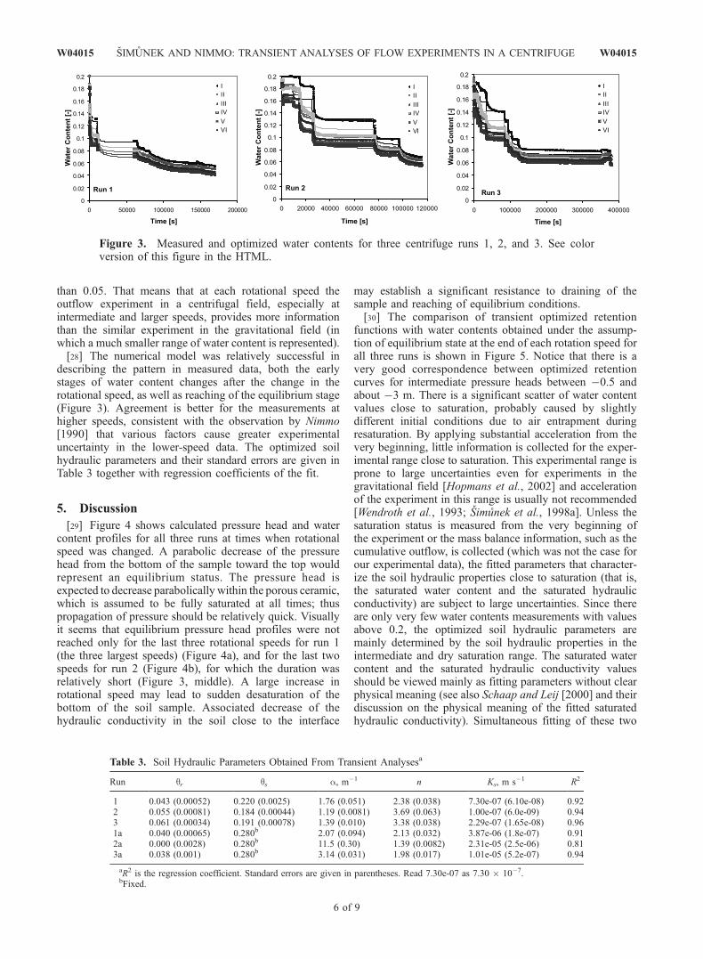
than 0.05. That means that at each rotational speed theoutflow experiment in a centrifugal field, especially atintermediate and larger speeds, provides more informationthan the similar experiment in the gravitational field (inwhich a much smaller range of water content is represented).[28] The numerical model was relatively successful in
describing the pattern in measured data, both the earlystages of water content changes after the change in therotational speed, as well as reaching of the equilibrium stage(Figure 3). Agreement is better for the measurements athigher speeds, consistent with the observation by Nimmo[1990] that various factors cause greater experimentaluncertainty in the lower-speed data. The optimized soilhydraulic parameters and their standard errors are given inTable 3 together with regression coefficients of the fit.
5. Discussion
[29] Figure 4 shows calculated pressure head and watercontent profiles for all three runs at times when rotationalspeed was changed. A parabolic decrease of the pressurehead from the bottom of the sample toward the top wouldrepresent an equilibrium status. The pressure head isexpected to decrease parabolically within the porous ceramic,which is assumed to be fully saturated at all times; thuspropagation of pressure should be relatively quick. Visuallyit seems that equilibrium pressure head profiles were notreached only for the last three rotational speeds for run 1(the three largest speeds) (Figure 4a), and for the last twospeeds for run 2 (Figure 4b), for which the duration wasrelatively short (Figure 3, middle). A large increase inrotational speed may lead to sudden desaturation of thebottom of the soil sample. Associated decrease of thehydraulic conductivity in the soil close to the interface
may establish a significant resistance to draining of thesample and reaching of equilibrium conditions.[30] The comparison of transient optimized retention
functions with water contents obtained under the assump-tion of equilibrium state at the end of each rotation speed forall three runs is shown in Figure 5. Notice that there is avery good correspondence between optimized retentioncurves for intermediate pressure heads between �0.5 andabout �3 m. There is a significant scatter of water contentvalues close to saturation, probably caused by slightlydifferent initial conditions due to air entrapment duringresaturation. By applying substantial acceleration from thevery beginning, little information is collected for the exper-imental range close to saturation. This experimental range isprone to large uncertainties even for experiments in thegravitational field [Hopmans et al., 2002] and accelerationof the experiment in this range is usually not recommended[Wendroth et al., 1993; Simunek et al., 1998a]. Unless thesaturation status is measured from the very beginning ofthe experiment or the mass balance information, such as thecumulative outflow, is collected (which was not the case forour experimental data), the fitted parameters that character-ize the soil hydraulic properties close to saturation (that is,the saturated water content and the saturated hydraulicconductivity) are subject to large uncertainties. Since thereare only very few water contents measurements with valuesabove 0.2, the optimized soil hydraulic parameters aremainly determined by the soil hydraulic properties in theintermediate and dry saturation range. The saturated watercontent and the saturated hydraulic conductivity valuesshould be viewed mainly as fitting parameters without clearphysical meaning (see also Schaap and Leij [2000] and theirdiscussion on the physical meaning of the fitted saturatedhydraulic conductivity). Simultaneous fitting of these two
Figure 3. Measured and optimized water contents for three centrifuge runs 1, 2, and 3. See colorversion of this figure in the HTML.
Table 3. Soil Hydraulic Parameters Obtained From Transient Analysesa
Run qr qs a, m�1 n Ks, m s�1 R2
1 0.043 (0.00052) 0.220 (0.0025) 1.76 (0.051) 2.38 (0.038) 7.30e-07 (6.10e-08) 0.922 0.055 (0.00081) 0.184 (0.00044) 1.19 (0.0081) 3.69 (0.063) 1.00e-07 (6.0e-09) 0.943 0.061 (0.00034) 0.191 (0.00078) 1.39 (0.010) 3.38 (0.038) 2.29e-07 (1.65e-08) 0.961a 0.040 (0.00065) 0.280b 2.07 (0.094) 2.13 (0.032) 3.87e-06 (1.8e-07) 0.912a 0.000 (0.0028) 0.280b 11.5 (0.30) 1.39 (0.0082) 2.31e-05 (2.5e-06) 0.813a 0.038 (0.001) 0.280b 3.14 (0.031) 1.98 (0.017) 1.01e-05 (5.2e-07) 0.94
aR2 is the regression coefficient. Standard errors are given in parentheses. Read 7.30e-07 as 7.30 � 10�7.bFixed.
6 of 9
W04015 SIMUNEK AND NIMMO: TRANSIENT ANALYSES OF FLOW EXPERIMENTS IN A CENTRIFUGE W04015

parameters together with the shape parameters, however, isrecommended [Hopmans et al., 2002] since it providesnumerical code with additional flexibility to describe soilhydraulic properties in the measuring range for which mostinformation is collected, i.e., intermediate and dry range.[31] There are slight differences also at the dry end, where
the optimization routine returned values of qr in the range of0.043 and 0.061. In run 1, a much greater rotation speedwas used for the last step (see Table 1), and thus muchsmaller pressure heads and water contents were registered inthis experiment compared to other two runs. Consequently,while the optimization program for run 1 could use actualinformation about water contents and pressure heads in arelatively dry range, in the other two runs that used slowerrotational speeds, the optimization program only extra-polated soil hydraulic properties in this range frommeasurement at higher-pressure heads.[32] Figure 6 shows retention curves resulting from both
the equilibrium and transient analyses. All retention curvesare in a relatively narrow range. There are again largerdifferences in obtained retention curves only close tosaturation and at the dry end. These differences are similarto those reported in Figure 5.[33] Finally, Figure 7 shows comparison of hydraulic
conductivity functions obtained using numerical inversionof transient centrifugal experiments and independentlymeasured hydraulic conductivities using steady state centri-fuge experiments [Nimmo et al., 1987]. Figure 7 also showsthe analytical function fitted to measured hydraulicconductivities by Nimmo et al. [1987]. Notice that allhydraulic conductivity functions pass in a relatively narrow
range around measured values, and that they deviatesignificantly between themselves only for pressure headsfor which there are no measurements. Extrapolation ofoptimized soil hydraulic functions beyond the range ofmeasurements is usually expected to be associated with ahigh level of uncertainty [e.g., Hopmans et al., 2002].
Figure 4. (top) Pressure heads and (bottom) water contents at times when rotation speed was changed:(a) run 1, (b) run 2, and (c) run 3. See color version of this figure in the HTML.
Figure 5. Optimized retention curves for three runscompared to water contents obtained assuming equilibriumat each time of change of rotational speed. See color versionof this figure in the HTML.
W04015 SIMUNEK AND NIMMO: TRANSIENT ANALYSES OF FLOW EXPERIMENTS IN A CENTRIFUGE
7 of 9
W04015

Hydraulic conductivity functions fitted to transient centrif-ugal data show similar shapes and values.
6. Summary
[34] High-speed centrifuges have been often used duringthe last two decades to measure water retention, andsaturated and unsaturated hydraulic conductivities [e.g.,Nimmo et al., 1987; Conca and Wright, 1992] of soil androck samples. However, a steady state analysis is generallyused to compute K(q) from the measurements. Recentadvances in centrifuge experiments allow measurements ofmultiple transient variables, such as pressure heads, watercontents, concentrations, and outflow rates during theexperiment, i.e., variables that can be used to advantagewith parameter estimation techniques.[35] In this paper we presented a modified version of
the Hydrus software package that can directly or inverselysimulate water flow in a centrifugal field, and the applica-tion of this new model to previously published data ofNimmo [1990]. Using time-variable water contents mea-sured at a sequence of several rotational speeds, wesuccessfully estimated soil hydraulic properties by numer-ical inversion of transient experiments. The optimized soilhydraulic properties compared well with those determinedusing equilibrium analysis and steady state experiments.[36] Similar parameter estimation procedures are often
used in soil physics for analyzing one-step and multistepoutflow experiments [Hopmans et al., 2002]. Multirotationexperiments in a centrifuge not only offer significant timesavings by accelerating time, but also provide significantlymore information for the parameter estimation procedure.Multistep outflow experiments in a gravitational field, ifcarried out for a sufficiently long time to reach steadyconditions, provide a single pair of the water content andpressure head at each pressure step that defines one datapoint of the retention curve. Multirotation experiments, onthe other hand, can provide multiple pairs of pressure headsand water contents for a single rotational speed. This is
because the pressure head changes significantly between thebottom and the top of the sample in a centrifugal field, whileit is almost uniform for the multistep experiment in agravitational field. The advantage of collecting multipleretention data points at one speed is partly overcome byincreasing nonlinearity of water content distribution withina measurement window over which the water content isaveraged compared to the usual gravity system. In transientconditions a wide range of pressure heads also occurs formultistep outflow experiments and these pressure heads canbe measured with tensiometers and used in the inverseanalyses. A detailed sensitivity analyses on both measuredand synthetic data, however, would then be required toreveal which experiment provides more information and ismore reliable to determine soil hydraulic properties. Itseems plausible that if multirotation experiments are carriedout for a sufficiently long time at each rotational speed toreach steady conditions, the collected data can providemultiple points of the retention curve that would warrant theoptimization of free form analytical functions such as thosesuggested by Bitterlich et al. [2004].
[37] Acknowledgment. The senior author would like to thank EarlMattson and Carl Palmer from Idaho National Laboratory for providingfunding to develop the numerical solver for the centrifugal conditions.
ReferencesAlemi, M. H., D. R. Nielsen, and J. W. Biggar (1976), Determining thehydraulic conductivity of soil cores by centrifugation, Soil Sci. Soc.Am. J., 40, 212–218.
Bear, J., M. Y. Corapcioglu, and J. Balakrishna (1984), Modeling ofcentrifugal filtration in unsaturated deformable porous media, Adv. WaterResour., 7, 150–167.
Bitterlich, S., W. Durner, S. C. Iden, and P. Knabner (2004), Inverseestimation of the unsaturated soil hydraulic properties from columnoutflow experiments using free-form parameterizations, Vadose Zone J.,3, 971–981.
Briggs, L. J., and J. W. McLane (1907), The moisture equivalent of soils,U.S. Bur. Soils Bull., 45, 23 pp.
Celia, M. A., E. T. Bououtas, and R. L. Zarba (1990), A general mass-conservative numerical solution for the unsaturated flow equation, WaterResour. Res., 26, 1483–1496.
Conca, J. L., and J. Wright (1992), A new technology for direct measure-ments of unsaturated transport, paper presented at the Nuclear and
Figure 7. Hydraulic conductivity functions obtained usingthe parameter estimation analyses of transient centrifugalexperiments and hydraulic conductivities measured usingsteady state analyses [Nimmo et al., 1987]. The thick solidline was fitted to measured data obtained from steady stateexperiments. See color version of this figure in the HTML.
Figure 6. Retention curves resulting from the equilibrium(SS) and transient (Transient) analyses. Number in thelegend refers to run number. See color version of this figurein the HTML.
8 of 9
W04015 SIMUNEK AND NIMMO: TRANSIENT ANALYSES OF FLOW EXPERIMENTS IN A CENTRIFUGE W04015
Hazardous Waste Management Spectrum ’92 Meeting, An. Nucl. Soc.,Boise, Idaho.
Conca, J. L., and J. A. Wright (1998), The UFA method for rapid, directmeasurement of unsaturated transport properties in soil, sediment, androck, Aust. J. Soil Res., 36, 291–315.
Culligan, P. J., D. A. Barry, and J. Y. Parlange (1997), Scaling unstableinfiltration in the vadose zone, Can. Geotech. J., 34(3), 466–470.
Dane, J. H., and J. W. Hopmans (2002), Hanging water column, in Methodsof Soil Analysis, part 4, Physical Methods, edited by J. H. Dane and G. C.Topp, pp. 680–683, Soil Sci. Soc. of Am., Madison, Wis.
Dane, J. H., and G. C. Topp (Eds.) (2002), Methods of Soil Analysis, part 1,Physical Methods, 3rd ed., Soil Sci. Soc. of Am., Madison, Wis.
Durner, W., E. B. Schultze, and T. Zuruhl (1999), State-of-the-art in inversemodeling of inflow/outflow experiments, in Characterization and Mea-surement of the Hydraulic Properties of Unsaturated Porous Media,edited by M. T. van Genuchten et al., pp. 661–681, Univ. of Calif.,Riverside.
Eching, S. O., and J. W. Hopmans (1993), Optimization of hydraulic func-tions from transient outflow and soil water pressure data, Soil Sci. Soc.Am. J., 57, 1167–1175.
Forbes, P. L. (1994), Simple and accurate methods for converting centrifugedata into drainage and imbibition capillary pressure curves, Log Anal.,35, 31–53.
Gardner, R. (1937), A method of measuring the capillary tension of soilmoisture over a wide moisture range, Soil Sci., 43, 277–283.
Gardner, W. R. (1956), Calculation of capillary conductivity from pressureplate outflow data, Soil Sci. Soc. Am. Proc., 20, 317–320.
Griffioen, J. W., P. J. Culligan, D. A. Barry, and K. Banno (1997),Centrifuge scaling of unstable infiltration, Recent Res. Dev. Soil Sci.,1, 29–41.
Hassler, G. L., and E. Brunner (1945), Measurement of capillary pressuresin small core samples, Trans. Am. Inst. Min. Metall. Pet. Eng., 160, 114–123.
Hopmans, J. W., J. Simunek, N. Romano, and W. Durner (2002), Inversemodeling of transient water flow, in Methods of Soil Analysis, part 1,Physical Methods, edited by J. H. Dane and G. C. Topp, pp. 963–1008,3rd ed., Soil Sci. Soc. of Am., Madison, Wis.
Kool, J. B., J. C. Parker, and M. T. van Genuchten (1985), Determining soilhydraulic properties from one-step outflow experiments by parameterestimation: I. Theory and numerical studies, Soil Sci. Soc. Am. J., 49,1348–1354.
Marquardt, D. W. (1963), An algorithm for least-squares estimation ofnonlinear parameters, SIAM J. Appl. Math., 11, 431–441.
Mattson, E. D., K. E. Baker, C. D. Palmer, R. W. Smith, and J. Simunek(2003), One-dimensional solute transport in variably saturated soil usinga geocentrifuge apparatus, Eos Trans. AGU, 84(46), Fall Meet. Suppl.,Abstract H22A-0906.
Mualem, Y. (1976), A new model for predicting the hydraulic conductivityof unsaturated porous media, Water Resour. Res., 12, 513–522.
Nakajima, H., E. D. Mattson, and A. T. Stadler (2003), Unsaturatedhydraulic properties determined from geocentrifuge tests, Eos Trans.AGU, 84(46), Fall Meet. Suppl., Abstract H22A-0908.
Nimmo, R. J. (1990), Experimental testing of transient unsaturated flowtheory at low water content in a centrifugal field, Water Resour. Res.,26(9), 1951–1960.
Nimmo, J. R., and K. C. Akstin (1988), Hydraulic conductivity of a sandysoil at low water content after compaction by various methods, Soil Sci.Soc. Am. J., 52, 303–310.
Nimmo, R. J., and K. A. Mello (1991), Centrifugal techniques formeasuring saturated hydraulic conductivity, Water Resour. Res., 27(6),1263–1269.
Nimmo, J. R., J. Rubin, and D. P. Hammermeister (1987), Unsaturated flowin a centrifugal field: Measurement of hydraulic conductivity and testingof Darcy’s law, Water Resour. Res., 23(1), 124–137.
Nimmo, J. R., K. S. Perkins, and A. M. Lewis (2002), Steady-statecentrifuge, in Methods of Soil Analysis, part 1, Physical Methods,3rd ed., edited by J. H. Dane and G. C. Topp, pp. 903–916, Soil Sci.Soc. of Am., Madison, Wis.
Paningbatan, E. P. (1980), Determination of soil moisture characteristic andhydraulic conductivity using a centrifuge, Ph.D. thesis, Univ. of Calif.,Davis.
Russell, M. B., and L. A. Richards (1938), The determination of soilmoisture energy relations by centrifugation, Soil Sci. Soc. Am. Proc.,3, 65–69.
Savvidou, C., and P. J. Culligan (1998), The application of centrifugemodeling to geo-environmental problems, Proc. Inst. Civ. Eng. Geotech.Eng., 131, 152–162.
Schaap, M. G., and F. J. Leij (2000), Improved prediction of unsaturatedhydraulic conductivity with the Mualem–van Genuchten model, Soil Sci.Soc. Am. J., 64, 843–851.
Sigda, J. M., and J. L. Wilson (2003), Are faults preferential flow pathsthrough semiarid and arid vadose zones?, Water Resour. Res., 39(8),1225, doi:10.1029/2002WR001406.
Simunek, J., and J. W. Hopmans (2002), Parameter optimization and non-linear fitting, in Methods of Soil Analysis, part 1, Physical Methods,3rd ed., edited by J. H. Dane and G. C. Topp, pp. 139–157, Soil Sci.Soc. of Am., Madison, Wis.
Simunek, J., O. Wendroth, and M. T. van Genuchten (1998a), A parameterestimation analysis of the evaporation method for determining soilhydraulic properties, Soil Sci. Soc. Am. J., 62, 894–905.
Simunek, J., M. Sejna, and M. T. van Genuchten (1998b), The HYDRUS-1D software package for simulating the one-dimensional movement ofwater, heat, and multiple solutes in variably-saturated media, version 2.0,Rep. IGWMC-TPS-70, 202 pp., Int. Ground Water Model. Cent., Colo.Sch. of Mines, Golden, Colo.
van Dam, J. C., J. N. M. Stricker, and P. Droogers (1994), Inverse methodto determine soil hydraulic functions from multistep outflow experiment,Soil Sci. Soc. Am. J., 58, 647–652.
van Genuchten, M. T. (1980), A closed-form equation for predicting thehydraulic conductivity of unsaturated soils, Soil Sci. Soc. Am. J., 44,892–898.
van Genuchten, M. T., F. J. Leij, and S. R. Yates (1991), The RETC codefor quantifying the hydraulic functions of unsaturated soils, Rep. EPA/600/2-91-065, U.S. Enviorn. Prot. Agency, Washington, D. C.
Wendroth, O., W. Ehlers, J. W. Hopmans, H. Kage, J. Halbertsma, andJ. H. M. Wosten (1993), Reevaluation of the evaporation method fordetermining hydraulic functions in unsaturated soils, Soil Sci. Soc. Am.J., 57, 1436–1443.
����������������������������J. R. Nimmo, U.S. Geological Survey, 345 Middlefield Road, MS-421,
Menlo Park, CA 94025, USA. ([email protected])J. Simunek, Department of Environmental Sciences, University of
California Riverside, Riverside, CA 92521, USA. ([email protected])
W04015 SIMUNEK AND NIMMO: TRANSIENT ANALYSES OF FLOW EXPERIMENTS IN A CENTRIFUGE
9 of 9
W04015