establishing a successful water/wastewater commissi oning...
TRANSCRIPT
Distributed with permission of Richard Birdsell and Mike Puccio by ISA 2011 Presented at 2011 Water and Waste Symposium; http://www.isa.org
Establishing a Successful Water/Wastewater Commissioning Program
Richard Birdsell, P.E., Orange County Sanitation District Mike Puccio, P.E., Orange County Sanitation District
THE CHALLENGE The goals of any water/wastewater utility engineering department are to deliver projects to their stakeholders that are on schedule, on budget, do the function intended and that can be operated and maintained. Commissioning is a critical component to accomplishing these goals. As in any construction industry, water/wastewater has been challenged with executing one of the most critical stages of a construction project, commissioning, at the end of the project when the risk of budgets being exhausted is very high and there is significant pressure to complete the contractor’s work. Another challenge is that the facility is operating during commissioning and when the contractor is done with all the specified testing, the owner starts operating and maintaining the next day. This requires careful planning and control throughout the design, construction and commissioning phases. For this paper commissioning will be defined as testing/start-up a project as well as the work related to preparing the project to be turned over to the operators and maintainers including:
• Equipment Testing • Piping, Tank and Structural Basin Testing • Utility System Testing • Control System Testing • Process Testing • Vendor Equipment Manuals • Vendor Equipment Training • Operations Manual (Designer Prepared) • Operations Training • As-Build Drawings
Distributed with permission of Richard Birdsell and Mike Puccio by ISA 2011 Presented at 2011 Water and Waste Symposium; http://www.isa.org
INTRODUCTION The Orange County Sanitation District (OCSD) collects, conveys, and treats approximately 230 million gallons of wastewater generated daily in its 471 square mile service area. In 2002, to improve effluent quality, increase treatment capacity and rehabilitate aging facilities, OCSD embarked on a Capital Improvement Program (CIP) valued at approximately $2.7 billion including:
• New 300 MGD Headworks Facility • New 30 MGD Trickling Filter Secondary Treatment Facility
• New 60 MGD Activated Sludge Secondary Treatment Facility • New 60 MGD Trickling Filter/Solids Contact Secondary Treatment Facility
• New 60 MGD Primary Treatment Expansion • New Co-Thickening and Dewatering Centrifuge Facility • New Primary Sludge Distribution Pump Station
• Rehabilitation of Primary Clarifiers, Secondary Treatment Facility, Digesters and Central Generation Facility
• Replacement of six Lift Stations
This CIP program created a challenge for the Engineering and Construction Department to start up and test many projects with parallel schedules and make them ready to be turned over to the Operations and Maintenance Department (O&M). PLANNING FOR COMMISSIONING With this many complicated projects in different phases of design and construction it was important to develop a detailed plan to commission that would include a cultural change with regards to commissioning in most departments of the organization. The Project Management Office and Engineering Design group were tasked with developing a plan to attack commissioning on a program basis. The following tasks would need to be accomplished in order to establish the commissioning program:
• Develop a separate commissioning phase for each project with a budget and schedule. • Develop a commissioning team for the program and commissioning teams for each project. • Establish tasks for design engineers to include on the plans and specification to facilitate
commissioning. • Develop a specification to define the contractor’s responsibility in commissioning. • Develop specification to define the contractor’s responsibility for vendor training and vendor
equipment manuals.
Distributed with permission of Richard Birdsell and Mike Puccio by ISA 2011 Presented at 2011 Water and Waste Symposium; http://www.isa.org
• Establish requirements for detailed testing procedures with pass/fail criteria. • Provide procedures, training and assistance to construction managers and inspectors to enforce
contract requirements during construction. • Develop post construction process acceptance testing requirements. • Develop lessons learned process.
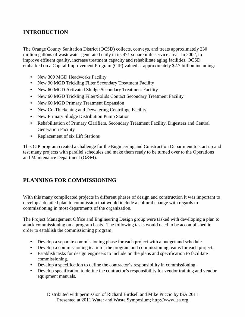
ESTABLISHING A PROJECT COMMISSIONING PHASE As discussed above, since commissioning usually takes place at the very end of projects that last for years, the project budget including the design consultant budget and the contractor budget are not in good shape. To ensure that Commissioning would be well budgeted and scheduled, a separate project phase was created at OCSD, see Figure 1.
Figure 1: OCSD Project Phases and Gate Meetings
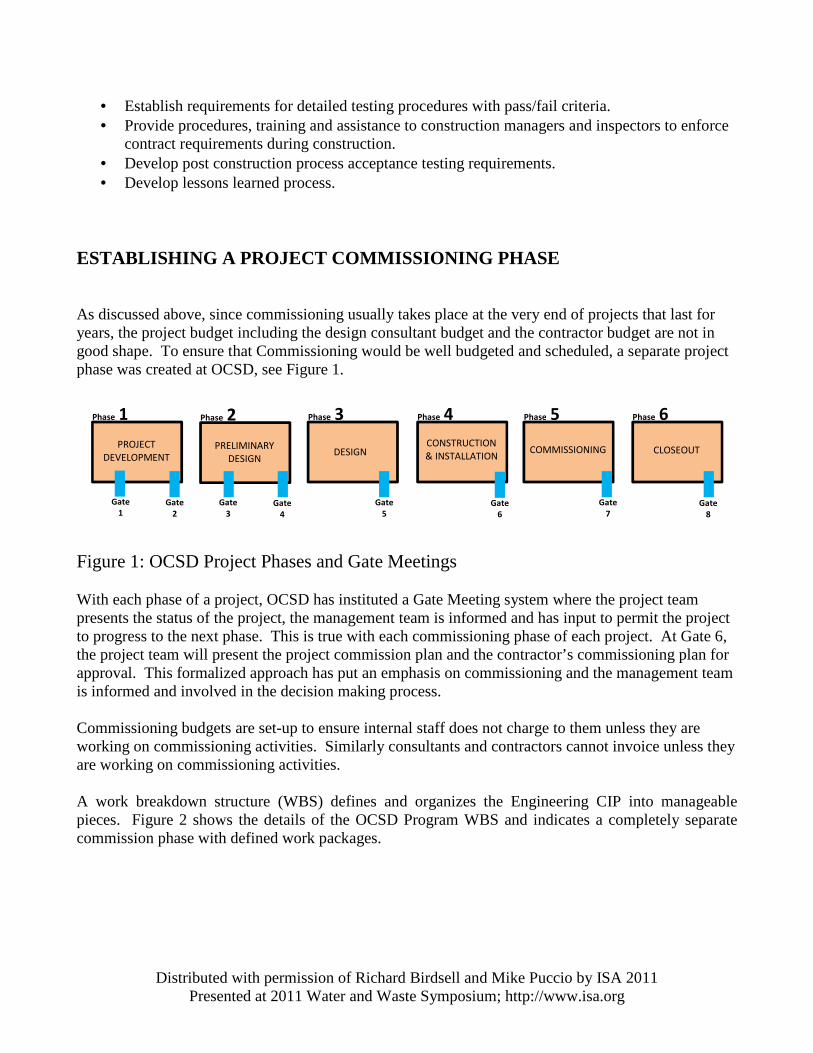
With each phase of a project, OCSD has instituted a Gate Meeting system where the project team presents the status of the project, the management team is informed and has input to permit the project to progress to the next phase. This is true with each commissioning phase of each project. At Gate 6, the project team will present the project commission plan and the contractor’s commissioning plan for approval. This formalized approach has put an emphasis on commissioning and the management team is informed and involved in the decision making process. Commissioning budgets are set-up to ensure internal staff does not charge to them unless they are working on commissioning activities. Similarly consultants and contractors cannot invoice unless they are working on commissioning activities. A work breakdown structure (WBS) defines and organizes the Engineering CIP into manageable pieces. Figure 2 shows the details of the OCSD Program WBS and indicates a completely separate commission phase with defined work packages.
Phase 1 Phase 2 Phase 3 Phase 4 Phase 5 Phase 6
PROJECT
DEVELOPMENT
PRELIMINARY
DESIGN DESIGN
CONSTRUCTION
& INSTALLATION COMMISSIONING CLOSEOUT
Gate
1
Gate
2
Gate
3
Gate
4
Gate
5
Gate
6
Gate
7
Gate
8
Distributed with permission of Richard Birdsell and Mike Puccio by ISA 2011 Presented at 2011 Water and Waste Symposium; http://www.isa.org
Figure 2: OCSD Program WBS Allocating time for commissioning is also very important to develop a realistic project schedule and having the contractor prepare a realistic baseline schedule. Continually using the data from recently completed projects, OCSD has been able to develop realistic project duration for commission phases. The bigger challenge has been getting our contractors to be realistic in developing their baseline schedules. OCSD has experienced some success in this by a combination of good definition of procedures expected for each phase of commissioning or by simply dictating durations of some or all of the commissioning phases. Either way, it is critical for the contractor to plan for the time and man-hours to successfully complete commissioning. If the reader receives nothing else from this paper they would have a great chance of properly commissioning a facility. ESTABLISH COMMISSIONING TEAMS All successful programs have an effective leader. When OCSD was looking to establish a leader for the commissioning program it focused on two attributes, understanding equipment level testing and understanding system level testing. The qualifications of the successful candidate turned out to be an instrumentation engineer with a strong field experience and strong mechanical background. The commissioning program lead responsibilities include:
Distributed with permission of Richard Birdsell and Mike Puccio by ISA 2011 Presented at 2011 Water and Waste Symposium; http://www.isa.org
• Author Commission Procedures • Author Commission Specification • Train Construction Managers and Inspectors on Commission • Track various project’s commissioning efforts • Serve as Project Commissioning Coordinator
Each project establishes a commission team during design and the team includes the following:
• OCSD Project Manager • OCSD Project Engineer • OCSD Resident Engineer/Construction Manager • OCSD Commissioning Coordinator • Design Consultant Representative • OCSD Operations Representative • OCSD Maintenance Representative • Contractor’s Commissioning Coordinator (Construction Phase only)
The team will meet to discuss requirements for commissioning during design and commissioning status during construction. The OCSD Commission Coordinator is responsible for the execution of the commissioning plan. COMMISSIONING IN DESIGN, CONSTRUCTION AND COMMISSIONING Commissioning is carried out during the three phases of the project. These are Design, Construction and Commissioning. Based on the operational process and the type of equipment the level of testing is established. A project installing a sump and sump pump will be quite different from a new Headworks project. But both projects should include a Commissioning specification. The Commissioning Specification will define the testing requirements, documentation requirements, and examples of procedures and test forms with the roles and responsibilities of the team players. This portion of the paper will expand on the procedures and test forms.
COMMISSIONING IN DESIGN
The commissioning specification should clearly define stages of commissioning, responsibilities of the Contractor, and Owner, qualifications of the commissioning coordinator and testing hours. The responsibilities which need to be addressed are defining which tests need to be witnessed by the owner, plant operations support, and supply of labor, material, tools, test water, manufacturers’ representative, and testing equipment. Because the commissioning documentation such as procedures, and test reports
Distributed with permission of Richard Birdsell and Mike Puccio by ISA 2011 Presented at 2011 Water and Waste Symposium; http://www.isa.org
start early in the construction phase it is recommended to have a commissioning coordinator. Another reason to have a commissioning coordinator is because most contractors are good at building but are not good at starting equipment. Establishing a project team including the design engineering, plant operations, maintenance and engineering will help open discussions on operations and maintenance requirements that can be included in the beginning of the design phase. The will help eliminate design rework and identify additional testing tie-in points, additional valve for testing or process isolation, identifying temporary electrical requirements, sources for temporary utilities, additional taps for pressure instruments used in testing, work restrictions and a plan to identifying locations for temporary flow meters used in testing. The testing requirements must be defined during design. The requirements for vibration and noise differ between types of equipment. The contract should include standalone specification which defines these testing/pass fail requirements. The individual specifications will be referenced back to the stand alone specification. For large variable speed pumps defining the test flow rates and speed in the specifications eliminates questions during flow testing and minimizes testing time. A commissioning plan is a useful tool. It can be divided into four sections, testing, training, schedule and planning and documentation turn over. The test plan should detail the sequential testing of each piece of equipment and system. The written plan should include step by step descriptions of the procedure for systematic testing of all equipment and systems installed under the contract. The commissioning plan should include equipment description/tag number, the purpose of the test; step by step requirements, pass/fail criteria, and identify test equipment required. The training plan identifies the craft to be trained, lesson plans for each class, and class evaluations for each class. The commissioning schedule must be coordinated with the construction schedule; it should include start dates and duration. Planning and documentation includes scheduling the participation of the Manufacturers’ As Built documentation, and breaking down the project into systems based on the equipment control, P&IDs and single line diagrams are useful tools for defining systems. There are many benefits to writing the commissioning plan during design: testing and verifying wiring, local and remote logic checks, and verifying panel, MCC and HMI displays. Some of these benefits include a final review of all logic and control strategy write up, verifying the P&IDs are correct, a final check of the I/O all instrumentation is supplied and the equipment is tested in all of the operating modes. The test plan can be reviewed; final buy in by the design team prevents wish lists at the end of construction. COMMISSIONING SPECIFICATION The Commissioning specification should identify the requirements for the Contractors Commissioning coordinator. The commission coordinator should have experience in operations and commissioning of facilities, equipment, electrical equipment and plant controls of similar type, size, and capacity. The Commissioning coordinator also needs the ability to write test plans, and prepare and update the
Distributed with permission of Richard Birdsell and Mike Puccio by ISA 2011 Presented at 2011 Water and Waste Symposium; http://www.isa.org
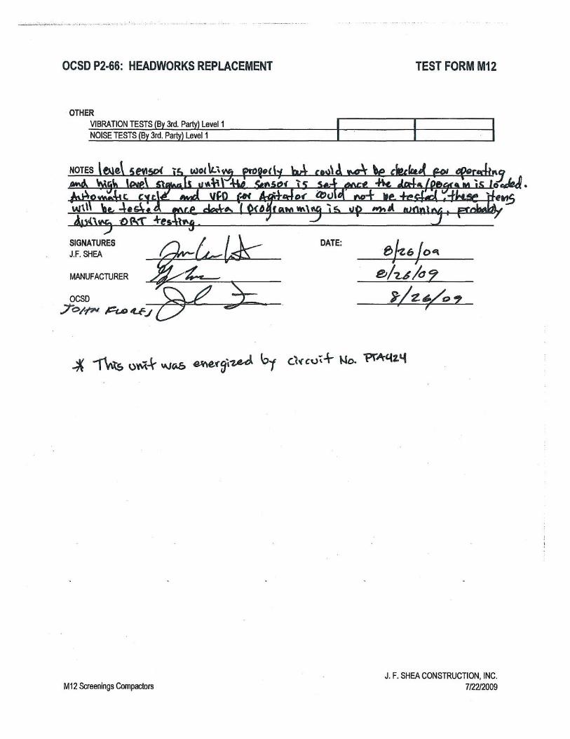
schedule. Another reason to have a commissioning coordinator is because most contractors are good at building but are not good at testing or starting up equipment. Another component of the Commissioning plan is defining the manpower limitations. Operations, engineering and inspection support is usually limited to 40 hours a week. Establishing start and end time work hours will help the contractor plan his work and minimize overtime. The commissioning plan should define the requirements for chemical, utilities, temporary power, and work restrictions. It should also define if testing of equipment will be with clean water before process is introduced is required. TEST FORMS Equipment verification testing forms included in the contract specification requirements allows the owner to verify the equipment supplied meets the contract. Piping pressure test forms, wire and cable resistance forms, calibration forms, are other types of useful test forms. Include in these forms a placeholder for the signatures of contractor and inspector along with the test date. FACTORY DEMONSTRATION TEST FORMS Factory test forms based on the project specifications are generated during design. As part of the submittal procedure the standard form is modified for the specific equipment. The Manufacturer’s is revised and insures the equipment testing will match the form. When the Manufacturer is finished with assembly they complete the form by signing the unwitnessed column on the form. The contractor submits the signed witness form before the owner witness test. This allows the Manufacturer to check the equipment before the witness test. Because the Manufacturer has performed the test he is familiar with the steps, has the test equipment ready thus saving time during the witness test. The witness test can be waived if the third party testing is implemented and the third party has a clear understanding of the tests required. If during testing problems arise they can be corrected at the factory rather than in the field. See the attachment A. COMMUNICATION TEST FORM A communications test form for verifying communications from the processor to the I/O is helpful. Although it is not conducted until just before commissioning it allows the contractor to verify communications before the final program is loaded. It also helps to verify the As Built drawings are
Distributed with permission of Richard Birdsell and Mike Puccio by ISA 2011 Presented at 2011 Water and Waste Symposium; http://www.isa.org
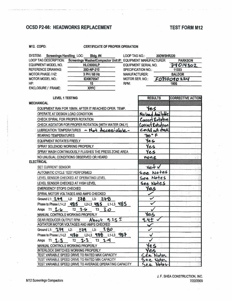
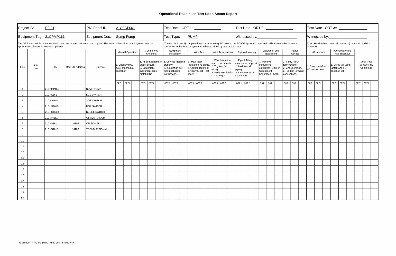
correct. If a redundant communications system is used this allow testing to continue upon a communications failure. See the attachment B. ELECTRICAL AND INSTRUMENTATION INSPECTION FORMS Inspection forms for Electrical and Instrumentation equipment give both the contractor and the owner’s inspection staff the pass/fail requirements and identify the information required for records. This will avoid confusion during testing. The contractor can also use his own forms with the required information included. See the attachment C. CERTIFICATE OF PROPER INSTALLATION (COPI) This Certificate of Proper Installation is a form submitted before installation of equipment by the Contractor. This form can be the manufacturers installation form with any project specific requirements included. Items typically included on the form is material verification, installation inspection requirements, such as belts tight, equipment alignment, installation per O&M manual, and are lubrication points accessible. This form is signed by the Manufacturer and the Contractor to verify the equipment meets the Contract and Manufacturers requirements. See the attachment D. CERTIFICATE OF PROPER OPERATION (COPO) The certificate of proper Operation is similar to the Certificate of Proper Installation. It is signed by the Contractor and Manufacturer it verify proper operation. See the attachment E. OPERATIONAL READINESS TEST (ORT) LOOP STATUS RECORDS This document is used to verify proper installation has been completed before testing of the equipment. The Status Record form has two columns, the first is by the contractor, and the second is for the owner witnessed sign off. This allows the contractor to verify the installation meets the contract requirements. Items that are checked are the equipment installation, tagging is installed and correct, wire tests have been completed and the I/O has been verified. See the attachment F.
Distributed with permission of Richard Birdsell and Mike Puccio by ISA 2011 Presented at 2011 Water and Waste Symposium; http://www.isa.org
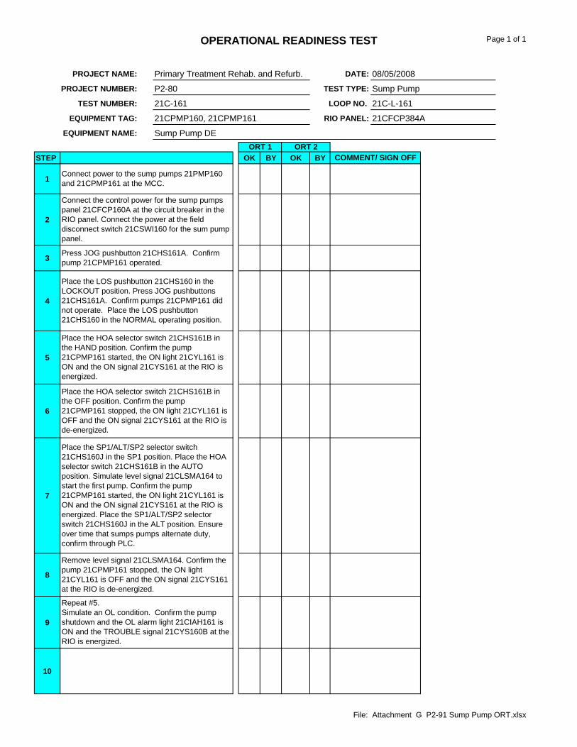
OPERATIONAL READINESS TEST PROCEDURES (ORT) The Operational Readiness Test procedure is a step by step procedure for testing a piece of equipment or instrument. The form has placeholders to indicate the equipment to be tested by description, and Equipment Tag number. The Loop number and panel number are also referenced. The procedure starts with confirming utilities are energized, operation in local and remote, verifies any control logic and verifies status conditions. The test form has two columns, the first is by the contractor, and the second is the owner witnessed sign off. The reason the two step process is needed is to insure the contractor is familiar with the test and verifies the equipment is operational and trouble shooting of any problems has already been completed. See the attachment G. FUNCTIONAL TEST FORMS (FAT) The FAT is a functional test of the control logic both local and remote. This can be accomplished without process, clean water or under normal operating conditions. Supply and exhaust fans and HVAC equipment are two examples of systems that do not require process. Where it is practical clean water tests are preferred. This allows testing without worrying about leaks, cleaning equipment which may need to be disassembled for process trouble shooting. The Functional Test is started after all ORTs have been completed. After the ORT is completed it is not required to open any motor controls, panel, inspect wiring, or calibration. See the attachment H. RELIABILITY ACCEPTANCE TEST (RAT) The RAT is started after all the functional tests are completed. Process is introduced and the equipment is operated under normal conditions. The process and equipment is monitored to verify the equipment starts properly and operates without equipment failure or alarms. Because of lead lag control strategies and/or standby equipment and to insure all equipment is operated, a plan must be in place that indicates what equipment is to be tested day by day. The second part of the RAT plan is to have an activity plan to verify operations throughout the day and by shift. See the attachment I.
The commissioning Specification will instruct the contractor to modify the ORT and FAT template procedures supplied to include all equipment. It will instruct the contractor which documents are required at each phase of testing; define the requirements to proceed to the next phase of testing.
Distributed with permission of Richard Birdsell and Mike Puccio by ISA 2011 Presented at 2011 Water and Waste Symposium; http://www.isa.org
COMMISSIONING DURING CONSTRUCTION Commissioning for a project is very sequential, however, not all equipment is available at the same time and a project is divided into phases. During commissioning the control logic could require modifications, installation mistakes arise, and equipment fails. The schedule needs to allow for these normal setbacks. At the beginning of a project monthly meetings to discuss issues are normal, when construction is about 50% complete, the commissioning meetings become weekly. When the project starts the owner witness phase the weekly meeting continue along with a brief meeting at the beginning of each day. This allows for issues to be discussed and resolved, manpower planning, and schedule updates. The commissioning plan needs to be incorporated in the overall schedule to insure the proper amount of time is allowed for commissioning. The experience level of the contractors commissioning coordinator is important to the success of the project. The commissioning coordinator needs to have experience in operating and commissioning facilities of similar size. It is helpful for the coordinator to have been a project manager with a good understanding of waste water processes, equipment, plant controls and electrical systems. Being a Grade V operator is a plus. It is beneficial to review the commissioning coordinators resume. The owner needs to review the commissioning procedures submitted by the contractor with all the stake holders. Correcting and adding comments to the procedures will pay off during the actual tests. It is important to include the pass or fail requirements in the procedure. Testing equipment at the factory is a benefit in a number of ways. The manufacturer knows what tests are required based on the FDT he submitted. If problems are observed during the tests they can be logged and corrected at the factory. This prevents rework in the field when time is critical. Factory tests should be included for mechanical equipment, pump flow tests for large pumps, control panels, control system panels, electrical switchgear and motor controls. Defined deliverables need to be defined to allow the contractor to proceed to the next phase of testing. Before the contractor is allowed to proceed to the next phase it should be agreed upon by operations and maintenance. Commissioning addressed during design, clear specifications, and agreed upon forms will make the end of the project progress smoother.
Unwitnessed Test Date _________________
Witnessed Test Date _________________
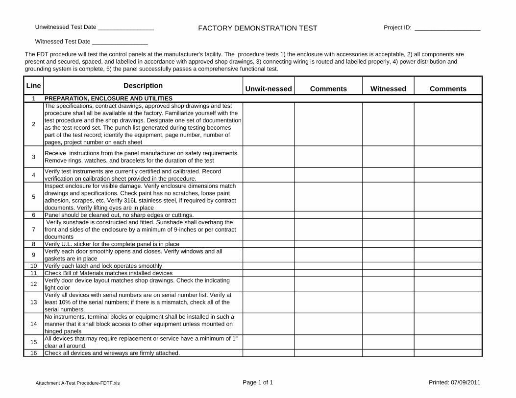
FACTORY DEMONSTRATION TEST Project ID: ____________________
Line Description Unwit-nessed Comments Witnessed Comments1 PREPARATION, ENCLOSURE AND UTILITIES
2
The specifications, contract drawings, approved shop drawings and test procedure shall all be available at the factory. Familiarize yourself with the test procedure and the shop drawings. Designate one set of documentation as the test record set. The punch list generated during testing becomes part of the test record; identify the equipment, page number, number of pages, project number on each sheet
3Receive instructions from the panel manufacturer on safety requirements. Remove rings, watches, and bracelets for the duration of the test
4Verify test instruments are currently certified and calibrated. Record verification on calibration sheet provided in the procedure.
5
Inspect enclosure for visible damage. Verify enclosure dimensions match drawings and specifications. Check paint has no scratches, loose paint adhesion, scrapes, etc. Verify 316L stainless steel, if required by contract documents. Verify lifting eyes are in place
6 Panel should be cleaned out, no sharp edges or cuttings.
7 Verify sunshade is constructed and fitted. Sunshade shall overhang the front and sides of the enclosure by a minimum of 9-inches or per contract documents
8 Verify U.L. sticker for the complete panel is in place
9Verify each door smoothly opens and closes. Verify windows and all gaskets are in place
10 Verify each latch and lock operates smoothly11 Check Bill of Materials matches installed devices
12Verify door device layout matches shop drawings. Check the indicating light color
13Verify all devices with serial numbers are on serial number list. Verify at least 10% of the serial numbers; if there is a mismatch, check all of the serial numbers.
14No instruments, terminal blocks or equipment shall be installed in such a manner that it shall block access to other equipment unless mounted on hinged panels
15All devices that may require replacement or service have a minimum of 1" clear all around.
16 Check all devices and wireways are firmly attached.
The FDT procedure will test the control panels at the manufacturer's facility. The procedure tests 1) the enclosure with accessories is acceptable, 2) all components are present and secured, spaced, and labelled in accordance with approved shop drawings, 3) connecting wiring is routed and labelled properly, 4) power distribution and grounding system is complete, 5) the panel successfully passes a comprehensive functional test.
Attachment A-Test Procedure-FDTF.xls Page 1 of 1 Printed: 07/09/2011
Unwitnessed Test Date _________________
Witnessed Test Date _________________
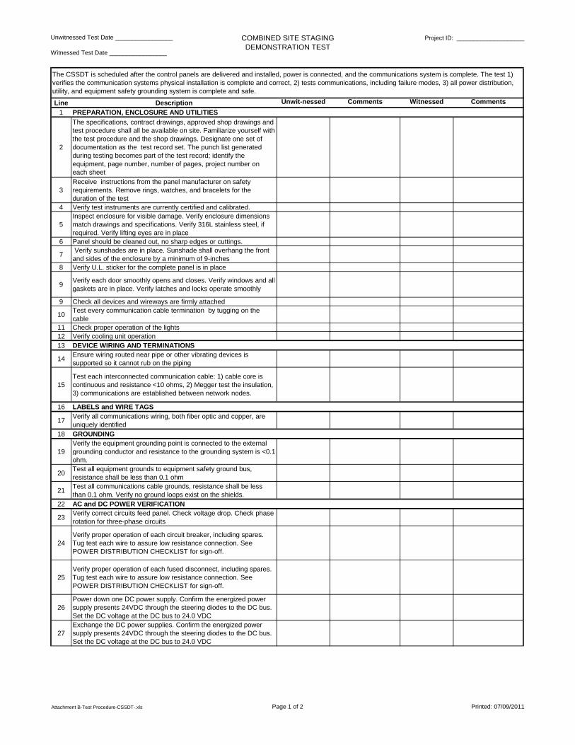
COMBINED SITE STAGING DEMONSTRATION TEST
Project ID: ____________________
Line Description Unwit-nessed Comments Witnessed Comments
1 PREPARATION, ENCLOSURE AND UTILITIES
2
The specifications, contract drawings, approved shop drawings and test procedure shall all be available on site. Familiarize yourself with the test procedure and the shop drawings. Designate one set of documentation as the test record set. The punch list generated during testing becomes part of the test record; identify the equipment, page number, number of pages, project number on each sheet
3Receive instructions from the panel manufacturer on safety requirements. Remove rings, watches, and bracelets for the duration of the test
4 Verify test instruments are currently certified and calibrated.
5Inspect enclosure for visible damage. Verify enclosure dimensions match drawings and specifications. Verify 316L stainless steel, if required. Verify lifting eyes are in place
6 Panel should be cleaned out, no sharp edges or cuttings.
7 Verify sunshades are in place. Sunshade shall overhang the front and sides of the enclosure by a minimum of 9-inches
8 Verify U.L. sticker for the complete panel is in place
9Verify each door smoothly opens and closes. Verify windows and all gaskets are in place. Verify latches and locks operate smoothly
9 Check all devices and wireways are firmly attached
10Test every communication cable termination by tugging on the cable
11 Check proper operation of the lights12 Verify cooling unit operation13 DEVICE WIRING AND TERMINATIONS
14Ensure wiring routed near pipe or other vibrating devices is supported so it cannot rub on the piping
15Test each interconnected communication cable: 1) cable core is continuous and resistance <10 ohms, 2) Megger test the insulation, 3) communications are established between network nodes.
16 LABELS and WIRE TAGS
17Verify all communications wiring, both fiber optic and copper, are uniquely identified
18 GROUNDING
19Verify the equipment grounding point is connected to the external grounding conductor and resistance to the grounding system is <0.1 ohm.
20Test all equipment grounds to equipment safety ground bus, resistance shall be less than 0.1 ohm
21Test all communications cable grounds, resistance shall be less than 0.1 ohm. Verify no ground loops exist on the shields.
22 AC and DC POWER VERIFICATION
23Verify correct circuits feed panel. Check voltage drop. Check phase rotation for three-phase circuits
24Verify proper operation of each circuit breaker, including spares. Tug test each wire to assure low resistance connection. See POWER DISTRIBUTION CHECKLIST for sign-off.
25Verify proper operation of each fused disconnect, including spares. Tug test each wire to assure low resistance connection. See POWER DISTRIBUTION CHECKLIST for sign-off.
26Power down one DC power supply. Confirm the energized power supply presents 24VDC through the steering diodes to the DC bus. Set the DC voltage at the DC bus to 24.0 VDC
27Exchange the DC power supplies. Confirm the energized power supply presents 24VDC through the steering diodes to the DC bus. Set the DC voltage at the DC bus to 24.0 VDC
The CSSDT is scheduled after the control panels are delivered and installed, power is connected, and the communications system is complete. The test 1) verifies the communication systems physical installation is complete and correct, 2) tests communications, including failure modes, 3) all power distribution, utility, and equipment safety grounding system is complete and safe.
Attachment B-Test Procedure-CSSDT-.xls Page 1 of 2 Printed: 07/09/2011
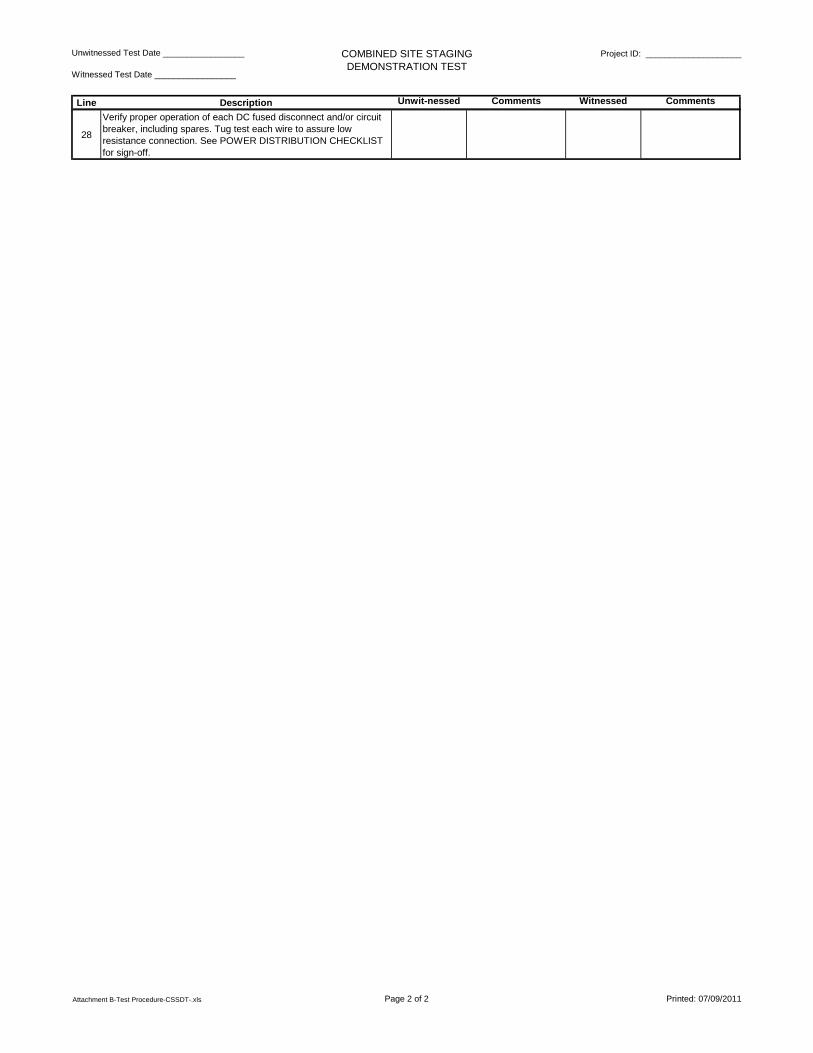
Unwitnessed Test Date _________________
Witnessed Test Date _________________
COMBINED SITE STAGING DEMONSTRATION TEST
Project ID: ____________________
Line Description Unwit-nessed Comments Witnessed Comments
28
Verify proper operation of each DC fused disconnect and/or circuit breaker, including spares. Tug test each wire to assure low resistance connection. See POWER DISTRIBUTION CHECKLIST for sign-off.
Attachment B-Test Procedure-CSSDT-.xls Page 2 of 2 Printed: 07/09/2011

Operational Readiness Test Loop Status Report
Project ID: P2-91 RIO Panel ID: 21CFCP001 Test Date - ORT 1: ______________ Test Date - ORT 2: ______________ Test Date - ORT 3:: _______________
Equipment Tag: 21CPMP161 Equipment Desc: Sump Pump Test Type: PUMP Witnessed by:_____________________ Witnessed by:____________________
ORT 1 ORT 2 ORT 1 ORT 2 ORT 1 ORT 2 ORT 1 ORT 2 ORT 1 ORT 2 ORT 1 ORT 2 ORT 1 ORT 2 ORT 1 ORT 2 ORT 1 ORT 2 ORT 1 ORT 2 ORT 1 ORT 2
1 21CPMP161 SUMP PUMP
2 21CHS161 LOS SWITCH
3 21CHS160A JOG SWITCH
4 21CHS161B HOA SWITCH
5 21CHS160H RESET SWITCH
6 21CIAH161 OL ALARM LIGHT
7 21CYS161 10108 ON SIGNAL
8 21CYS161B 10109 TROUBLE SIGNAL
9
10
11
12
13
14
15
16
17
18
19
20
3) stroke all valves, bump all motors, 4) prove all hardwire interlocks.
Piping & Valving
1. Pipe & fitting clearances, support.2. Leak test all piping.3. Instruments per spec sheet.
LTNILDNo
Real I/O Address
Loop Test Successfully Completed
Calibration and adjustment
1. Perform instrument calibration. Sign off Component Calibration Sheet.
PanelInterface
I/O Interface I/O software and
HMI checkout
1. Verify R I/O terminations.2. Check shields. 3.Tug test terminal connections.
1. Check terminal to I/O connections.
1. Verify I/O using laptop and I/O checkoff list.
1. Check valve, gate, etc manual operation
The ORT is scheduled after installation and instrument calibration is complete. The test confirms the control system, less the application software, is ready for operation.
Manual Operation Wire Test
Service
1. Wire & terminal match documents.2. Tug test field wiring.3. Verify termination screw torque.
Wire Terminations
1. Devices installed properly.2. Installation per manufacturer's instructions.
Equipment Installation
1. Max. loop resistance <5 ohms.2. Ground loop test.3. Verify Elect. Test sheet
The test includes 1) complete loop check for every I/O point to the SCADA system, 2) test and calibration of all equipment connected to the SCADA system whether provided by contractor or not
Line
Component Checkout
1. All components in place, secure.2. Equipment, instrument tags match ILDs
Attachment F P2-91 Sump Pump Loop Status.xlsx
OPERATIONAL READINESS TEST Page 1 of 1
STEP OK BY OK BY
1
2
3
4
5
6
7
8
9
10
Repeat #5. Simulate an OL condition. Confirm the pump shutdown and the OL alarm light 21CIAH161 is ON and the TROUBLE signal 21CYS160B at the RIO is energized.
PROJECT NAME: DATE:
PROJECT NUMBER: TEST TYPE:
EQUIPMENT NAME:
RIO PANEL:
Sump Pump DE
21CPMP160, 21CPMP161
TEST NUMBER: LOOP NO. 21C-L-161
08/05/2008Primary Treatment Rehab. and Refurb.
COMMENT/ SIGN OFF
Connect power to the sump pumps 21PMP160 and 21CPMP161 at the MCC.
Place the HOA selector switch 21CHS161B in the HAND position. Confirm the pump 21CPMP161 started, the ON light 21CYL161 is ON and the ON signal 21CYS161 at the RIO is energized.
Place the HOA selector switch 21CHS161B in the OFF position. Confirm the pump 21CPMP161 stopped, the ON light 21CYL161 is OFF and the ON signal 21CYS161 at the RIO is de-energized.
Remove level signal 21CLSMA164. Confirm the pump 21CPMP161 stopped, the ON light 21CYL161 is OFF and the ON signal 21CYS161 at the RIO is de-energized.
Press JOG pushbutton 21CHS161A. Confirm pump 21CPMP161 operated.
Place the SP1/ALT/SP2 selector switch 21CHS160J in the SP1 position. Place the HOA selector switch 21CHS161B in the AUTO position. Simulate level signal 21CLSMA164 to start the first pump. Confirm the pump 21CPMP161 started, the ON light 21CYL161 is ON and the ON signal 21CYS161 at the RIO is energized. Place the SP1/ALT/SP2 selector switch 21CHS160J in the ALT position. Ensure over time that sumps pumps alternate duty, confirm through PLC.
Place the LOS pushbutton 21CHS160 in the LOCKOUT position. Press JOG pushbuttons 21CHS161A. Confirm pumps 21CPMP161 did not operate. Place the LOS pushbutton 21CHS160 in the NORMAL operating position.
Connect the control power for the sump pumps panel 21CFCP160A at the circuit breaker in the RIO panel. Connect the power at the field disconnect switch 21CSWI160 for the sum pump panel.
21C-161
P2-80 Sump Pump
ORT 1 ORT 2
EQUIPMENT TAG: 21CFCP384A
File: Attachment G P2-91 Sump Pump ORT.xlsx
ORANGE COUNTY SANITATION DISTRICT JOB NO. P2-91
PRIMARY SLUDGE FEED SYSTEM
COMMISSIONING FUNCTIONAL ACCEPTANCE TEST (FAT) PROCEDURE
C:\Data\ISA\ISA_WWAC2011_conference\FINAL_COPIES\Birdsell,Puccio_Commis\Attachment H P2-91 FAT Procedure.docx Page 1 of 2 9/7/2011
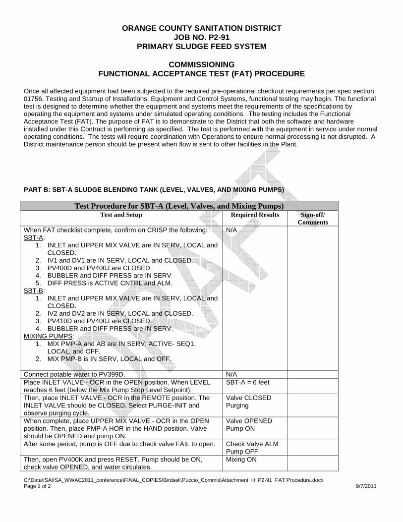
Once all affected equipment had been subjected to the required pre-operational checkout requirements per spec section 01756, Testing and Startup of Installations, Equipment and Control Systems, functional testing may begin. The functional test is designed to determine whether the equipment and systems meet the requirements of the specifications by operating the equipment and systems under simulated operating conditions. The testing includes the Functional Acceptance Test (FAT). The purpose of FAT is to demonstrate to the District that both the software and hardware installed under this Contract is performing as specified. The test is performed with the equipment in service under normal operating conditions. The tests will require coordination with Operations to ensure normal processing is not disrupted. A District maintenance person should be present when flow is sent to other facilities in the Plant. PART B: SBT-A SLUDGE BLENDING TANK (LEVEL, VALVES, AND MIXING PUMPS)
Test Procedure for SBT-A (Level, Valves, and Mixing Pumps) Test and Setup Required Results Sign-off/
Comments When FAT checklist complete, confirm on CRISP the following: SBT-A:
1. INLET and UPPER MIX VALVE are IN SERV, LOCAL and CLOSED.
2. IV1 and DV1 are IN SERV, LOCAL and CLOSED. 3. PV400D and PV400J are CLOSED. 4. BUBBLER and DIFF PRESS are IN SERV 5. DIFF PRESS is ACTIVE CNTRL and ALM.
SBT-B: 1. INLET and UPPER MIX VALVE are IN SERV, LOCAL and
CLOSED. 2. IV2 and DV2 are IN SERV, LOCAL and CLOSED. 3. PV410D and PV400J are CLOSED. 4. BUBBLER and DIFF PRESS are IN SERV.
MIXING PUMPS: 1. MIX PMP-A and AB are IN SERV, ACTIVE- SEQ1,
LOCAL, and OFF. 2. MIX PMP-B is IN SERV, LOCAL and OFF.
N/A
Connect potable water to PV399D. N/A Place INLET VALVE - OCR in the OPEN position. When LEVEL reaches 6 feet (below the Mix Pump Stop Level Setpoint).
SBT-A = 6 feet
Then, place INLET VALVE - OCR in the REMOTE position. The INLET VALVE should be CLOSED. Select PURGE-INIT and observe purging cycle.
Valve CLOSED Purging
When complete, place UPPER MIX VALVE - OCR in the OPEN position. Then, place PMP-A HOR in the HAND position. Valve should be OPENED and pump ON.
Valve OPENED Pump ON
After some period, pump is OFF due to check valve FAIL to open. Check Valve ALM Pump OFF
Then, open PV400K and press RESET. Pump should be ON, check valve OPENED, and water circulates.
Mixing ON

ORANGE COUNTY SANITATION DISTRICT JOB NO. P2-91
PRIMARY SLUDGE FEED SYSTEM
COMMISSIONING FUNCTIONAL ACCEPTANCE TEST (FAT) PROCEDURE
C:\Data\ISA\ISA_WWAC2011_conference\FINAL_COPIES\Birdsell,Puccio_Commis\Attachment H P2-91 FAT Procedure.docx Page 2 of 2 9/7/2011
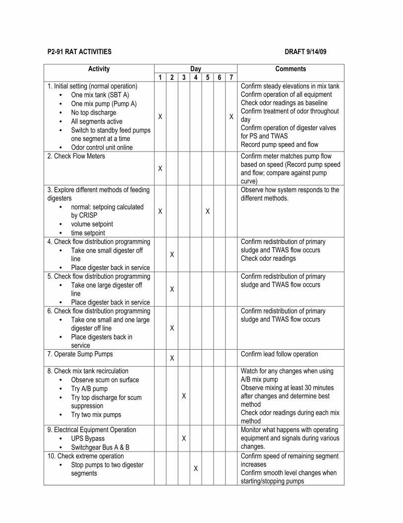
P2-91 RAT ACTIVITIES DRAFT 9/14/09
Activity Day Comments
1 2 3 4 5 6 7
1. Initial setting (normal operation)
• One mix tank (SBT A)
• One mix pump (Pump A)
• No top discharge
• All segments active
• Switch to standby feed pumps one segment at a time
• Odor control unit online
X X
Confirm steady elevations in mix tank Confirm operation of all equipment Check odor readings as baseline Confirm treatment of odor throughout day Confirm operation of digester valves for PS and TWAS Record pump speed and flow
2. Check Flow Meters
X
Confirm meter matches pump flow based on speed (Record pump speed and flow; compare against pump curve)
3. Explore different methods of feeding digesters
• normal: setpoing calculated by CRISP
• volume setpoint
• time setpoint
X X
Observe how system responds to the different methods.
4. Check flow distribution programming
• Take one small digester off line
• Place digester back in service
X
Confirm redistribution of primary sludge and TWAS flow occurs Check odor readings
5. Check flow distribution programming
• Take one large digester off line
• Place digester back in service
X
Confirm redistribution of primary sludge and TWAS flow occurs
6. Check flow distribution programming
• Take one small and one large digester off line
• Place digesters back in service
X
Confirm redistribution of primary sludge and TWAS flow occurs
7. Operate Sump Pumps
X Confirm lead follow operation
8. Check mix tank recirculation
• Observe scum on surface
• Try A/B pump
• Try top discharge for scum suppression
• Try two mix pumps
X
Watch for any changes when using A/B mix pump Observe mixing at least 30 minutes after changes and determine best method Check odor readings during each mix method
9. Electrical Equipment Operation
• UPS Bypass
• Switchgear Bus A & B
X
Monitor what happens with operating equipment and signals during various changes.
10. Check extreme operation
• Stop pumps to two digester segments
X
Confirm speed of remaining segment increases Confirm smooth level changes when starting/stopping pumps
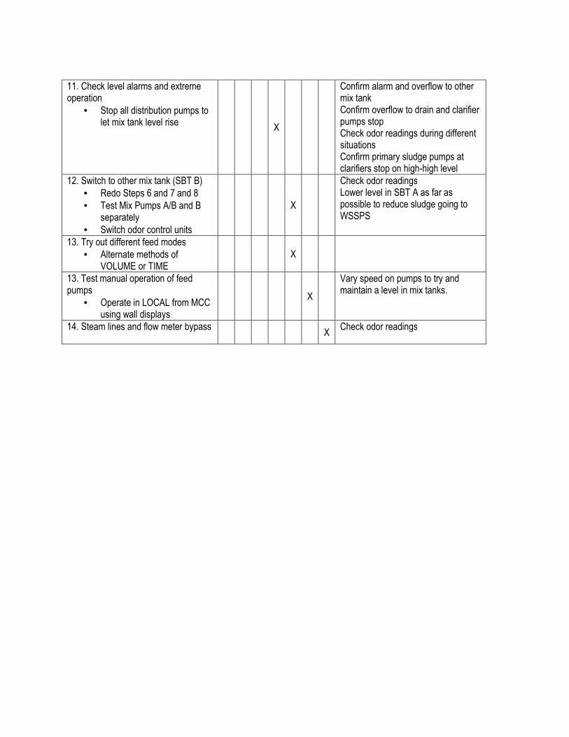
11. Check level alarms and extreme operation
• Stop all distribution pumps to let mix tank level rise
X
Confirm alarm and overflow to other mix tank Confirm overflow to drain and clarifier pumps stop Check odor readings during different situations Confirm primary sludge pumps at clarifiers stop on high-high level
12. Switch to other mix tank (SBT B)
• Redo Steps 6 and 7 and 8
• Test Mix Pumps A/B and B separately
• Switch odor control units
X
Check odor readings Lower level in SBT A as far as possible to reduce sludge going to WSSPS
13. Try out different feed modes
• Alternate methods of VOLUME or TIME
X
13. Test manual operation of feed pumps
• Operate in LOCAL from MCC using wall displays
X
Vary speed on pumps to try and maintain a level in mix tanks.
14. Steam lines and flow meter bypass
X Check odor readings
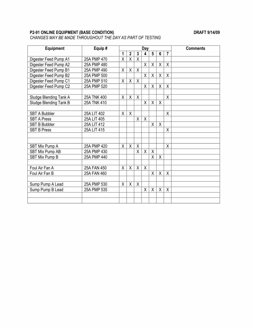
P2-91 ONLINE EQUIPMENT (BASE CONDITION) DRAFT 9/14/09 CHANGES MAY BE MADE THROUGHOUT THE DAY AS PART OF TESTING
Equipment Equip # Day Comments
1 2 3 4 5 6 7
Digester Feed Pump A1 25A PMP 470 X X X
Digester Feed Pump A2 25A PMP 480 X X X X
Digester Feed Pump B1 25A PMP 490 X X X
Digester Feed Pump B2 25A PMP 500 X X X X
Digester Feed Pump C1 25A PMP 510 X X X
Digester Feed Pump C2 25A PMP 520 X X X X
Sludge Blending Tank A 25A TNK 400 X X X X
Sludge Blending Tank B 25A TNK 410 X X X
SBT A Bubbler 25A LIT 402 X X X
SBT A Press 25A LIT 405 X X
SBT B Bubbler 25A LIT 412 X X
SBT B Press 25A LIT 415 X
SBT Mix Pump A 25A PMP 420 X X X X
SBT Mix Pump AB 25A PMP 430 X X X
SBT Mix Pump B 25A PMP 440 X X
Foul Air Fan A 25A FAN 450 X X X X
Foul Air Fan B 25A FAN 460 X X X
Sump Pump A Lead 25A PMP 530 X X X
Sump Pump B Lead 25A PMP 535 X X X X