erosion sediment control · 2019-03-27 · environment waikato 6 erosion and sediment control in...
TRANSCRIPT
January 2009www.ew.govt.nz
Guidelines for Soil Disturbing Activities
erosionsediment control
Please note the following sections are no longer relevant. Please refer to the corresponding fact sheets on the website:
3. Sediment Control Practices 3.1 Sediment Retention Pond 3.2 Silt Fence 3.4 Hay Bale Barrier (these are no longer considered suitable control devices) 3.6 Decanting Earth Bund
Please note there are now additional controls with fact sheets: Silt Sock/Filter Log
erosion & sediment control Guidelines for Soil Disturbing Activities
1
erosion & sediment controlGuidelines for Soil Disturbing Activities
Erosion & Sediment Control Guidelines for Soil Disturbing Activities January 2009
Environment Waikato Technical Report No.2009/02ISSN 1172-4005 (Print)ISSN 1177-9284 (Online)
Acknowledging the use of Auckland Regional Council Technical Publication Number 90: Erosion and Sediment Control Guidelines for Land Disturbing Activities in the Auckland Region.

Environment Waikato 2
erosion & sediment control Guidelines for Soil Disturbing Activities
3
1. Principles 91.1 Types of Erosion 91.1 Factors Influencing the Erosion Process 111.2 The ‘Ten Commandments’ of Erosion and Sediment Control 121.3 Types of Land Disturbing Activities Undertaken 14
2. Erosion Control Practices 172.1 Runoff Diversion Channel/Bund 192.2 Contour Drain 212.3 Watertable Drains 232.4 Water Cut-offs 252.5 Watertable Culverts 272.6 Sediment Pits 292.7 Berm bunds 312.8 Benched Slope 332.9 Rock Check Dam 352.10 Topsoil 372.11 Revegetation Techniques 39
2.11.1 Seeding 392.11.2 Hydroseeding 412.11.3 Mulching 432.11.4 Turfing 45
2.12 Geosynthetic Erosion Control Systems (GECS) 472.13 Stabilised Construction Entrance 492.14 Pipe/Flume Drop Structure 512.15 Level Spreader 552.16 Surface Roughening 57
3. Sediment Control Practices 593.1 Sediment Retention Pond 613.2 Silt fence 753.3 Super Silt Fence 793.4 Hay Bale Barrier 833.5 Stormwater Inlet Protection 853.6 Decanting Earth Bund 873.7 Sump/Sediment Pit 89
Table of contents

Environment Waikato 4
4. Works Within A Watercourse 914.1 Temporary Watercourse Crossings 934.2 Temporary Watercourse Diversion 954.3 Permanent Watercourse Crossings 99
4.3.1 Bridges 1014.3.2 Culvert Crossings 103
4.4 Rock Outlet Protection 107
5. Quarries 1096. Vegetation Removal 1117. Glossary 115
erosion & sediment control Guidelines for Soil Disturbing Activities
5
These guidelines have two main objectives:
a) To provide users, ranging from those directly associated with various soil disturbing activities to interest groups, with a series of comprehensive guidelines for erosion and sediment control by:
• outlining the principles of erosion and sediment control and the sediment transfer process;
• providing a range of erosion and sediment control practices to be implemented on various soil disturbing activities.
b) To minimise adverse environmental effects of soil disturbing activities through appropriate use and design of erosion and sediment control techniques.
How These Guidelines Work
These guidelines are based on the Auckland Regional Council’s Technical Publication Number 90, titled “Erosion and Sediment Control – Guidelines for Land Disturbing Activities”.
These guidelines focus on the principles and practices of erosion and sediment control for various soil disturbing activities. They should be used during planning for earthworks projects. They should also be used during the development of an Erosion and Sediment Control Plan for a project and during development of consent applications for earthworks projects. The erosion and sediment control measures and criteria outlined in these guidelines are minimum standards and in many cases higher standards may be required.
The introduction to these guidelines describes the need for erosion and sediment controls in the Waikato Region. Section 1 describes the basic principles of erosion and sediment control. This section describes basic types of erosion, factors that influence the erosion process, the ‘Ten Commandments’ of erosion and sediment control, and common types of land disturbing activities undertaken in the Waikato Region. Section 2 describes practices designed to prevent erosion from occurring. Section 3 describes practices for removing sediment from water once erosion and sediment transport have occurred. Specific erosion and sediment control practices are sometimes required for works in watercourses, for quarries and during vegetation removal, and these are described in Sections 4, 5 and 6 respectively. Finally, a glossary and references complete the guidelines.
Environment Waikato staff are available for further advice and can be contacted on Environment Waikato’s Freephone 0800 800 401.
Environment Waikato 6
Erosion and Sediment Control in the Waikato Region
Significant areas of land are stripped of vegetation or laid bare each year in the Waikato Region for construction of subdivisions, roads, cleanfills and other developments. Without protection measures, transformation of this land can result in accelerated on-site erosion and greatly increased sedimentation of waterways, lakes, estuaries and harbours.
Significant quantities of sediment are discharged from bare earth surfaces where appropriate erosion and sediment control measures are not implemented.
Various studies indicate there is a 10 to 100 times increase in sediment yield from construction sites compared with that produced from pastoral land, while data from the United States suggests that there may be up to 1000 times the sediment yield from disturbed sites during construction compared with permanent forest cover.
The adverse ecological effects caused by sediment in waterways include: • Modified or destroyed in-stream values. • Modified estuarine and coastal habitats. • Smothering and abrading of fauna and flora. • Changes in food sources and interruption of
lifecycles.
There is often a total change to in-stream communities. Recovery times from the effects of sediment deposition are more likely to be measured in years rather than months. In addition to ecological changes, there may be damage to water pumps and other structures, the quality of water supplies usually diminishes, localised flooding can occur and there is a loss of aesthetic appeal.
Current Legislation
The Resource Management Act 1991 (RMA) establishes Environment Waikato’s statutory responsibilities for resource management. The purpose of the RMA is to promote the sustainable management of natural and physical resources. ‘Sustainable management’ is defined in Section 5 of the Act as:
‘managing the use, development and protection of natural and physical resources in a way or at a rate, which enables people and communities to provide for their social, economic, and cultural wellbeing and for their health and safety while: a) sustaining the potential of natural and physical
resources (excluding minerals) to meet the reasonably foreseeable needs of future generations; and
b) safeguarding the life supporting capacity of air, water, soil and ecosystems; and ‘
c) avoiding, remedying or mitigating any adverse effects of activities on the environment.’
Consents and Permitted Activities for Earthworks
Some earthworks activities require consents from Environment Waikato. Consents may be required where earthworks are near streams, lakes, wetlands, or coastal waters, or where the works are on steep land, or over large areas, or when permitted activity discharge standards cannot be met. Consents may be required for stormwater discharges from earthworks sites. Large-scale vegetation clearance (such as forest harvesting) and quarry operations may also require consents. Consent requirements are described in the Waikato Regional Plan. A copy of this Plan can be found on our website www.ew.govt.nz.
Activities that do not require consents are called Permitted Activities. The Waikato Regional Plan also has conditions for Permitted Activities which may apply to earthworks projects. It is very important that where earthworks are being undertaken as Permitted Activities, the conditions of the Permitted Activity Rules are complied with at all times. The permitted activity rules have stringent discharge standards which cannot be easily met on larger sites. If the permitted activity rules discharge standards cannot be met at all times then resource consent/s should be obtained
erosion & sediment control Guidelines for Soil Disturbing Activities
7
for the project. These Rules can be found on our website. If there is any doubt about these requirements, you should contact Environment Waikato.
When is Erosion and Sediment Control Required?
All projects involving soil disturbing activities in the Waikato Region must incorporate erosion and sediment controls as an integral part of development. On all projects, erosion and sediment controls should be in place before earthworks commence and should be removed only after the site has been fully stabilised to protect it from erosion. The principles and practices within these guidelines should be referred to, and staff at Environment Waikato contacted for further advice if required.
Works Within a Watercourse Any works within a watercourse must be carefully planned because controlling sediment generation from these activities is difficult. These guidelines include a number of erosion and sediment control measures that can used for realignment, piping, culverting and stabilisation works. Techniques for minimising sediment generation and discharge when undertaking works within a watercourse are outlined in Section 4 of these guidelines. As stated in the introduction, consents may be required when undertaking such works, and contact should be made with Environment Waikato staff to discuss the specific details of the proposed activity.
CleanfillsThese guidelines do not include a specific section on cleanfill operations, but standard earthworks erosion and sediment control practices are appropriate for cleanfill operations.
Soils of the Waikato Region
Soils vary considerably throughout the Region.
Soils in the south-east of the Region (Taupo and the upper catchments of the Waikato River) are formed from recent airfall tephra and can be categorised as weakly weathered and of low cohesion. These are highly erodible pumice and raw volcanic soils which require a particular focus on control of overland flow when being worked.
The Waikato Basin and the Hauraki Plains are predominantly loamlands derived from well weathered tephra, some of which are river sorted. Although these soils are less erodible than the recent soils the presence of a clay component can cause visual effects and water quality degradation as a result of sediment laden runoff. This also applies to localised highly weathered soils which can release high volumes of dispersive clay resulting in significant downstream effects.
Organic soils (peats) are also a major soil group in the Waikato Basin and Lower Hauraki Plains. Working these soils does not normally result in significant downstream effects apart from a possible increase in staining and debris.
The north of the Region (Pukekohe - Pukekawa) has much older Hamilton Ash soils which form well structured, free draining, volcanic loamy clays. These soils generally have low erodibility, however because of the large ped size will entrain readily in concentrated overland flow.
Clay soils, common in the Coromandel area, contain fine soil particles that take a much longer time to settle out of water than coarser silt sized particles. Larger and more numerous sediment control measures may not be very effective in limiting the off-site transfer of sediment on clay soils. As a result more emphasis may be required on erosion control for clay soils compared to other soil types.
The hill country of the Region has soils derived from a variety of sedimentary parent material ranging from limestone around Waitomo to the shattered mudstones of the Mokauiti Valley. Folded/ uplifted landforms in some cases has resulted in soils on tilted parent material having deep seated mass movement. Erosion of this form may require engineering solutions, which might include such measures as drainage to reduce slip plane lubrication and buttress support.

8Environment Waikato
erosion & sediment control Guidelines for Soil Disturbing Activities
Principles9
Types of Erosion 1.1
Erosion is the process whereby the land surface is worn away by the action of water, wind, ice or other geological processes. The resultant displaced material is known as sediment. Sedimentation is the deposition of this eroded material. Accelerated erosion, caused primarily by human development activities, is generally much more rapid than natural erosion.
The basic erosion process is detachment, transport and deposition (sedimentation). Water is the usual eroding agent and transport medium, through raindrop impact and overland flow energy. Water dislodges exposed soil particles and transports them downslope. Runoff and streamflow transport the eroded soil particles to the final receiving environment where sedimentation occurs.
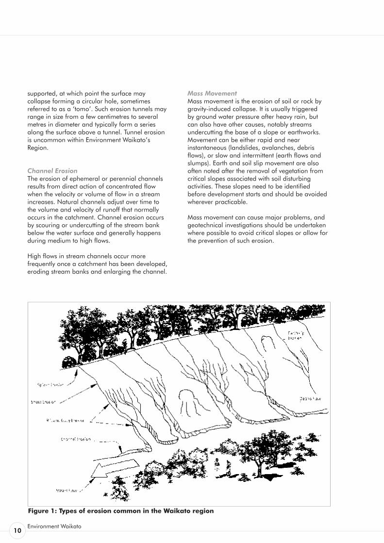
There are seven main types of erosion associated with soil disturbing activities:
1. Splash erosion 2. Sheet erosion 3. Rill erosion 4. Gully erosion 5. Tunnel erosion 6. Channel erosion 7. Mass movement
Splash Erosion Soil erosion is a mechanical process that requires energy. Much of this energy is supplied by falling raindrops.
The impact of a single raindrop on a soil surface or on a thin film of water may break up the soil aggregates and cause individual particles to be thrown into the air. If this occurs on a slope then some particles will move upslope, but the net effect due to gravity will cause splashed particles to move downslope. Splash erosion is directly related to the size, distribution, shape, velocity and direction of the raindrop.
The erosive ability of splash erosion is enhanced by intense rainstorms.
Sheet Erosion When rainfall intensity exceeds the infiltration rate of a soil and the capacity of the available surface detention, excess water moves downslope, transporting soil particles detached by splash erosion.
Sheet erosion or wash erosion is the uniform removal of soil in thin layers by the forces of raindrops and overland flow. It can be a very significant erosive process because it can cover large areas of sloping land and may go unnoticed for some time. Sheet erosion can be recognised by soil deposition at the bottom of a slope, or by the appearance of light coloured subsoil material on the surface. If left unattended, sheet erosion of topsoils will gradually remove the nutrients and organic matter important to re-vegetation, and will eventually result in loss of soil productivity on contributing slopes and elevated sediment concentrations in receiving waters.
Rill Erosion Rill erosion is the removal of soil by runoff moving in concentrated flows. As the flow changes from sheet flow to deeper flow in these channels, or rills, the velocity and turbulence of the flow increases, and the energy of this flow is able to both detach and transport soil particles.
Rill erosion has been estimated to be the dominant contributor to erosion on hill slopes.
Gully Erosion Gully erosion is the removal of soil by running water resulting in the formation of channels greater than 300 mm deep. Gullies can be distinguished from rills when normal agricultural tillage operations cannot obliterate them.
The following are the processes which act in forming gullies: • waterfall erosion at the head of the gully • channel erosion • raindrop splash • diffuse flow from the side of the gully or from
seepage• slides or mass movement of soil within the gully.
A gully may develop and grow rapidly and their formation may generate a considerable amount of erosion. Therefore, their prevention and remediation is vital for erosion control.
Tunnel Erosion Tunnel erosion, or piping is the removal of subsurface soil by subsurface water while the surface soil remains relatively intact. This produces long cavities beneath the ground surface, which may enlarge until the soil surface is no longer
Principles1.
10Environment Waikato
supported, at which point the surface may collapse forming a circular hole, sometimes referred to as a ‘tomo’. Such erosion tunnels may range in size from a few centimetres to several metres in diameter and typically form a series along the surface above a tunnel. Tunnel erosion is uncommon within Environment Waikato’s Region.
Channel Erosion The erosion of ephemeral or perennial channels results from direct action of concentrated flow when the velocity or volume of flow in a stream increases. Natural channels adjust over time to the volume and velocity of runoff that normally occurs in the catchment. Channel erosion occurs by scouring or undercutting of the stream bank below the water surface and generally happens during medium to high flows.
High flows in stream channels occur more frequently once a catchment has been developed, eroding stream banks and enlarging the channel.
Mass Movement Mass movement is the erosion of soil or rock by gravity-induced collapse. It is usually triggered by ground water pressure after heavy rain, but can also have other causes, notably streams undercutting the base of a slope or earthworks. Movement can be either rapid and near instantaneous (landslides, avalanches, debris flows), or slow and intermittent (earth flows and slumps). Earth and soil slip movement are also often noted after the removal of vegetation from critical slopes associated with soil disturbing activities. These slopes need to be identified before development starts and should be avoided wherever practicable.
Mass movement can cause major problems, and geotechnical investigations should be undertaken where possible to avoid critical slopes or allow for the prevention of such erosion.
Figure 1: Types of erosion common in the Waikato region
erosion & sediment control Guidelines for Soil Disturbing Activities
Principles11
Factors Influencing the Erosion 1.1 Process
The main factors influencing soil erosion are climate, soil characteristics, topography, ground cover and evapotranspiration.
Climate Climate affects erosion potential both directly and indirectly. The direct relationship arises from the action of rain - a driving force of erosion - where raindrops dislodge soil particles and runoff carries them away.
The annual pattern of rainfall and temperature change, by and large, determines the extent and growth rate of vegetation. This is critical, because vegetation is one of the most important forms of erosion control.
Soil Characteristics Four soil characteristics are important in determining soil erodibility:
• Soil texture refers to the particle sizes making up a particular soil and their relative proportions. Sand, silt and clay are the three major soil particle classes.
• Organic matter improves soil structure and increases permeability, water holding capacity and soil fertility.
• Soil permeability refers to the ability of the soil to allow air and water to move through the soil. Soils with a higher permeability produce less runoff at a lower rate than soils with low permeability. Engineered fills have a very low permeability, resulting in increased levels of potentially erosive runoff.
• Soil structure is the degree that soil particles are arranged into aggregates (peds). A granular structure is the most desirable in both agricultural and erosion control terms. When the soil surface is compacted or crusted, water tends to runoff rather than infiltrate. Erosion potential increases with increased runoff.
Topography Slope length and slope angle are critical factors in erosion potential because they play a large part in determining the velocity of runoff. Long continuous slopes allow runoff to build up velocity and to concentrate flow. This produces rill and gully erosion.
The shape of a slope also has a major bearing on erosion potential. The base of a slope is more susceptible to erosion than the top because runoff arriving there is moving faster and is more concentrated. However, deposition may occur at the base of concave slopes where slope angle diminishes.
Ground Cover Ground cover includes vegetation and surface treatment such as mulches and geotextiles. Vegetation is one of the most effective long term forms of erosion control for protecting surfaces that have been disturbed. Vegetation shields the soil surface from the impact of falling rain, slows the velocity of runoff, holds soil particles in place and maintains the soil’s capacity to absorb water.
Evapotranspiration Due to high evapotranspiration and reduced rainfall in the summer period, soil moisture levels are often so low that irrigation or watering is needed to achieve the moisture levels needed for plant growth. Evapotranspiration rates and the number of days of soil moisture deficit vary across the Region. Careful consideration needs to be given to evapotranspiration when attempting to establish a vegetative cover and prevent erosion.
12Environment Waikato
The ‘Ten Commandments’ of 1.2 Erosion and Sediment Control
1. Minimise Disturbance Fit land development to land sensitivity.
Some parts of a site should never be worked and others need very careful working. Watch out for and avoid areas that are wet (streams, wetlands, springs), have steep or fragile soils or are conservation sites or features.
Adopt a minimum earthworks strategy (low impact design) - ideally only clear areas required for structures or access.
Show all Limits of Disturbance on the Erosion and Sediment Control Plan (E&SCP). On site, clearly show Limits of Disturbance using fences, signs and flags.
2. Stage Construction Carrying out bulk earthworks over the whole site maximises the time and area of soil that is exposed and prone to erosion. “Construction staging”, where the site has earthworks undertaken in small units over time with progressive revegetation, limits erosion.
Careful planning is needed. Temporary stockpiles, access and utility service installation all need to be planned. Construction staging differs from sequencing. Sequencing sets out the order of construction to contractors.
Detail both construction staging and sequencing in the E&SCP.
3. Protect Steep Slopes Existing steep slopes should be avoided. If clearing is absolutely necessary. runoff from above the site can be diverted away from the exposed slope to minimise erosion. If steep slopes are worked and need stabilisation, traditional vegetative covers like topsoiling and seeding may not be enough - special protection is often needed.
Highlight steep areas on the E&SCP showing Limits of Disturbance and any works and areas for special protection.
4. Protect Watercourses Existing streams, watercourses, and proposed drainage patterns need to be mapped. Clearing may not be permitted adjacent to a watercourse unless the works have been approved.
Where undertaken, works that cross or disturb the watercourse are also likely to require resource consents.
Map all watercourses and show all Limits of Disturbance and protection measures. Show all practices to be used to protect new drainage channels. Indicate crossings or disturbances and associated construction methods in the E&SCP.
5. Stabilise Exposed Areas Rapidly The ultimate objective is to fully stabilise disturbed soils with vegetation after each stage and at specific milestones within stages. Methods are site specific and can range from conventional sowing through to straw mulching. Mulching is the most effective instant protection.
Clearly define time limits for grass and mulch covers, outline grass species and define conditions for temporary cover in the case of severe erosion or poor germination in the E&SCP.
6. Install Perimeter Controls Perimeter controls above the site keep clean runoff out of the worked area - a critical factor for effective erosion control. Perimeter controls can also retain or direct sediment laden runoff within the site. Common perimeter controls are diversion drains, silt fences and earth bunds.
Detail the type and extent of perimeter controls in the E&SCP along with design parameters.
erosion & sediment control Guidelines for Soil Disturbing Activities
Principles13
7. Employ Detention Devices Even with the best erosion and sediment practices, earthworks will discharge sediment-laden runoff during storms. Along with erosion control measures, sediment retention structures are needed to capture runoff so sediment generated can settle out. The presence of fine grained soils means sediment retention ponds are often not highly effective. Ensure the other control measures used are appropriate for the project and adequately protect the receiving environment.
Include sediment retention structure design specifications, detailed inspection and maintenance schedules of structures in the E&SCP.
8. Experience and Training A trained and experienced contractor is an important element of an E&SCP. These people are responsible for installing and maintaining erosion and sediment control practices. Such staff can save project time and money by identifying threatened areas early on and putting into place correct practices.
At each earthworks site, there should be a person whose responsibility it is to oversee the erosion and sediment control practices. It is often useful for Environment Waikato monitoring staff to meet with this person for a pre-construction meeting, for regular inspection visits (including a pre-wintering meeting), and a final inspection. For details about available erosion and sediment control courses, contact Environment Waikato.
9. Make Sure the Plan Evolves An effective E&SCP is modified as the project progresses from bulk earthworks to project completion. Factors such as weather, changes to grade and altered drainage can all mean changes to planned erosion and sediment control practices.
Update the E&SCP to suit site adjustments in time for the pre-construction meeting and initial inspection of installed erosion and sediment controls, and make sure it is regularly referred to and available on site.
10. Assess and Adjust Inspect, monitor and maintain control measures.
Assessment of controls is especially important following a storm. A large or intense storm will leave erosion and sediment controls in need of repair, reinforcement or cleaning out. Repairing without delay reduces further soil loss and environmental damage.
Assessment and adjustment is an important erosion and sediment control practice - make sure it figures prominently in the E&SCP.
Assign responsibility for implementing the E&SCP and monitoring control measures as the project progresses.
14Environment Waikato
Types of Land Disturbing 1.3 Activities Undertaken
The following are the main types of soil disturbing activities undertaken in the Waikato Region, which may require the use of erosion and sediment controls, and these are discussed in these guidelines:
1. trenching 2. watercourse works 3. cleanfills 4. small sites (such as house lots) 5. earthworks/projects (major cut to fill) 6. roading/tracking 7. quarries and vegetation removal.
The following is a brief summary of key considerations for minimising adverse environmental effects of these activities that are not found in the detailed description of erosion and sediment control measures in sections 2 and 3 of the guidelines.
Trenching Trenching, usually for installing utility services, often happens towards the end of the bulk earthworks phase of a project. The following points need to be considered when trenching.
• The project needs to be undertaken in appropriately sized stages such that the area exposed can be fully stabilised within an acceptable timeframe.
• If trenching affects existing erosion and sediment control measures that are part of the overall development, those measures should be reinstated as soon as possible. Contingency measures should be put in place until the original measures are reinstated or replaced.
• All trenching operators working within a larger site must be familiar with the overall Erosion and Sediment Control Plan for the site and must comply with this approved plan.
• Independent erosion and sediment control measures detailed in these guidelines should be employed for the trenching operation.
• Topsoil and subsoils should be stockpiled separately adjacent to the trench so that at the completion of the operation, these soils can be replaced in the appropriate order and vegetation established.
• When trenching through overland flow paths, give special consideration to the diversion of any flows, which may occur during trenching, as well as reinstating and stabilising the overland flow path.
Works Within a Watercourse Works within a watercourse should be avoided wherever possible, with all alternatives considered beforehand. Where watercourse works are unavoidable, they will create sedimentation downstream, so the following points should be carefully considered when undertaking these works.
• Have all alternatives been considered?
• Install a stabilised diversion so that works can be undertaken in the dry and reinstate the stream flow only after these areas have been appropriately stabilised. If a diversion is not a viable option, then ensure the alternative options are fully considered.
• Carry out works during a dry time of the year when stream flows are low and the likelihood of a storm is low.
• Keep the duration of works short.
• Identify in-stream values so as to avoid critical periods such as fish spawning periods and the whitebait season.
• Consider the direct short and long term impacts of culverts or in-stream structures and install appropriately designed fish-pass provisions.
• Be sure to inform all downstream users, for example water-users, of potential downstream sediment discharges.
erosion & sediment control Guidelines for Soil Disturbing Activities
Principles15
Cleanfills Cleanfills dispose of unwanted fill material.
Soil disturbing activities associated with cleanfills range from haul roads and access areas to tip faces and dumping areas. Several controls are needed for adequate erosion and sediment control on such sites and the following points should be carefully considered when undertaking such operations:
• Erosion and sediment controls should be installed in accordance with these guidelines and appropriate maintenance undertaken.
• Staging of cleanfill operations is critical and a programme of progressive stabilisation of all cleanfill sites should be part of each operation.
Small Sites The cumulative impact from small sites can be considerable and in some areas may cumulatively discharge as much sediment as large earthworks sites. Often, stormwater systems are in place but there are no, or minimal, erosion and sediment controls on the site. This results in sediment discharging through an efficient conveyance system (the stormwater system) directly to the receiving environment.
The following points need to be considered when undertaking small site development:
• Erosion and sediment controls should be installed either on an individual site-by-site basis or a combination of the sites, in accordance with these guidelines.
• Stormwater runoff from small sites needs careful planning in terms of the location of roof down pipes so that runoff across bare sites does not scour soils.
• Areas of exposed soils should be stabilised upon completion of earthworks, including topsoil and subsoil stockpiles, lawn areas and accessways.
Earthworks Earthworks include a wide range of activities from cleanfilling operations (defined above) through to earthworks associated with industrial, commercial and residential developments. Earthworks have a major potential to generate large amounts of sediment, and if not controlled appropriately, can lead to large sediment discharges. Planning of these developments is critical to ensure that the activity is undertaken appropriately, and in a controlled manner to avoid unnecessary impacts on receiving environments. The ‘Ten Commandments’ outline the critical features of an earthworks operation.
The following are further key points contractors need to be aware of when undertaking earthworks operations.
• Emphasis should be placed on erosion control, rather than sediment control, because preventing sediment generation is the best means of preventing sediment discharge from earthworks sites.
• Always produce an Erosion and Sediment Control Plan (E&SCP) for an earthworks operation. Be sure that all parties involved with the operation, including subcontractors, are familiar with and have access to a current copy of this Plan.
• Always update the E&SCP with major variations on the site. Keep this up-to-date version in the site office at all times.
• Plan ahead and undertake consultation with necessary parties as required.
• Install appropriate controls in accordance with the E&SCP and be sure that the design specifications are appropriate for the operation.
• Install subsurface drainage as required (to an agreed methodology) to divert subsurface clean water past control structures and areas of disturbance as appropriate.

16Environment Waikato
Roading/Tracking Like trenching, the linear nature of roading poses challenges for erosion and sediment control. Measures need to be carefully planned to ensure controls are successful. Often the operation can be undertaken sequentially, stabilising worked areas as they are completed. This minimises the total sediment generating area of the proposal and helps prevent unnecessary road maintenance.
The following are some key points to consider when working through a roading proposal.
• Provide enough room for effective erosion and sediment control measures. Often the road corridor itself can involve the whole designation area and no room remains for such controls. Where space is a constraint, make sure that the erosion and sediment controls will give the necessary protection to downstream receiving environments.
• Incorporate stormwater design into the E&SCP. This removes the need to revisit the area to install stormwater systems and the unnecessary extra earthworks that their construction would require.
• Keep the areas of road corridor exposed at any one time to a limit that can be practically stabilised with hardfill or by vegetative means, to minimise the exposed area at risk.
• When crossing watercourses, look for alternative routes and alternative designs and implement the option which provides the best environmental alternative.
• Control all upslope catchment runoff, diverting clean water around or safely through the area of disturbance.
Quarries and Vegetation Removal Measures in these guidelines are suitable for quarry and vegetation removal operations. However, the long term nature of many quarries and the clear felling of whole catchments during vegetation removal operations mean that some special erosion and sediment control measures need to be implemented. Careful planning of such operations is thus critical. The key areas where attention is required are discussed in detail in sections 5 and 6 of these guidelines and should be read in conjunction with the other erosion and sediment controls also detailed.
erosion & sediment control Guidelines for Soil Disturbing Activities
Erosion Control Practices 17
Sections 2 and 3 outline minimum criteria for the design, construction and implementation of a range of erosion and sediment control measures commonly used on earthworks sites and on other soil disturbing activities. These measures form one aspect of erosion and sediment control on any site, and should always be used in conjunction with the measures outlined in the Ten Principles of Erosion and Sediment Control in Section 1 of these guidelines.
The most effective form of erosion control is to minimise the area of disturbance, retaining as much existing vegetation as possible. This is especially important on steep slopes or in the vicinity of watercourses, where no single measure will adequately control the erosion and transport of sediment, and where receiving environments may be highly sensitive.
The criteria outlined are the minimum standard for each measure. Each soil disturbing activity must be assessed on an individual basis, and in many cases higher standards may be required.
For every practice, these guidelines outline the following: • definition • purpose • application • design/construction specifications • comments • maintenance.
Symbols shown alongside controls are listed in Appendix 1.
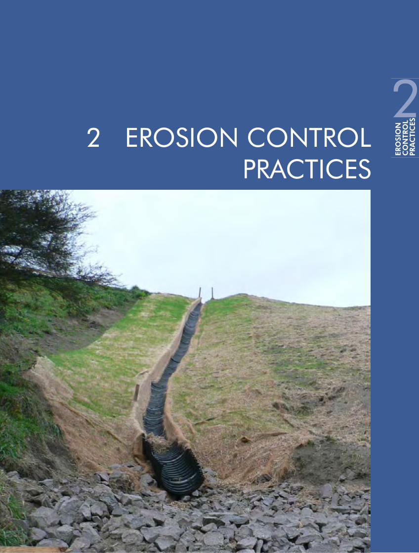
Erosion Control Practices2.

18Environment Waikato
erosion & sediment control Guidelines for Soil Disturbing Activities
Erosion Control Practices 19
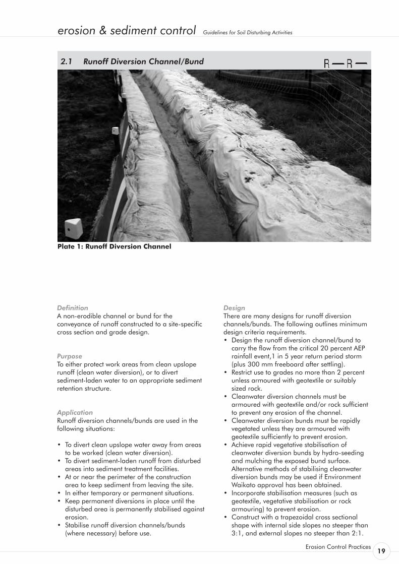
Definition A non-erodible channel or bund for the conveyance of runoff constructed to a site-specific cross section and grade design.
Purpose To either protect work areas from clean upslope runoff (clean water diversion), or to divert sediment-laden water to an appropriate sediment retention structure.
Application Runoff diversion channels/bunds are used in the following situations:
• To divert clean upslope water away from areas to be worked (clean water diversion).
• To divert sediment-laden runoff from disturbed areas into sediment treatment facilities.
• At or near the perimeter of the construction area to keep sediment from leaving the site.
• In either temporary or permanent situations. • Keep permanent diversions in place until the
disturbed area is permanently stabilised against erosion.
• Stabilise runoff diversion channels/bunds (where necessary) before use.
Runoff Diversion Channel/Bund 2.1
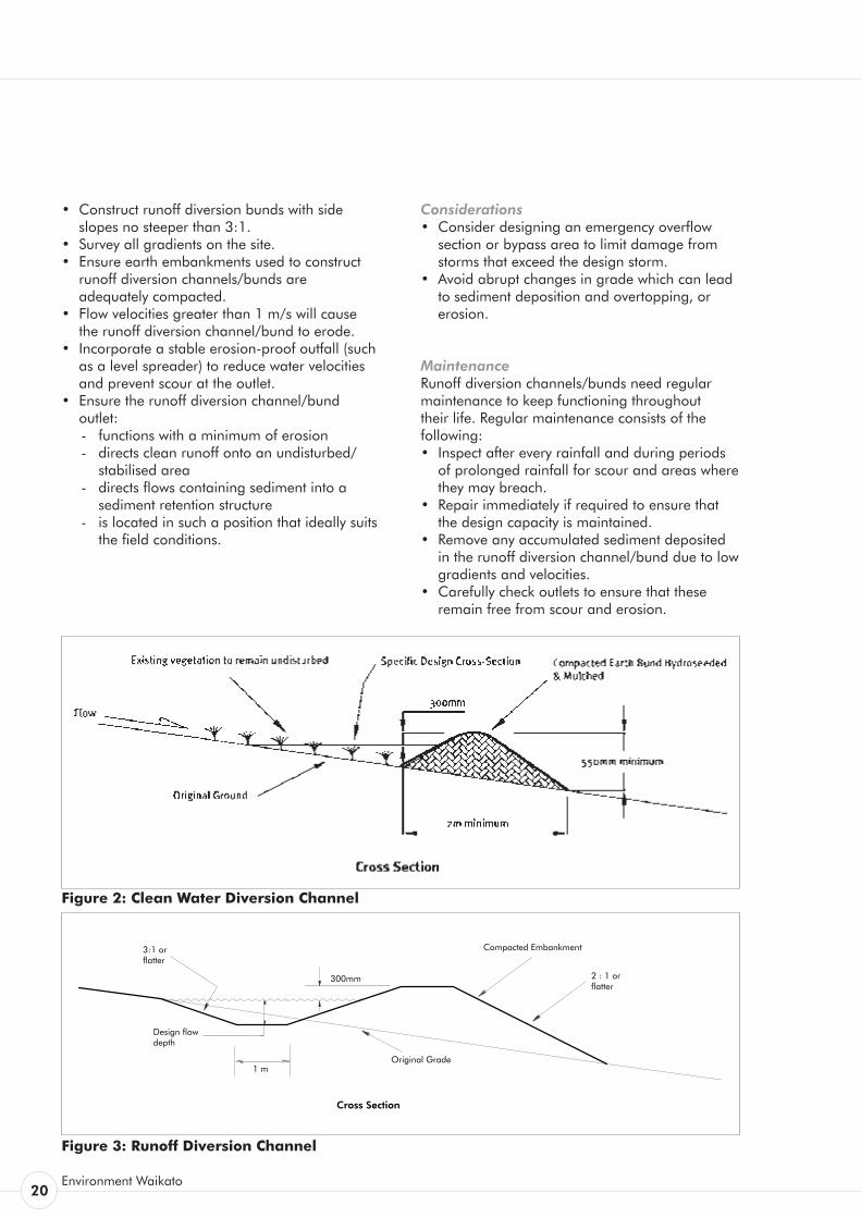
Design There are many designs for runoff diversion channels/bunds. The following outlines minimum design criteria requirements. • Design the runoff diversion channel/bund to
carry the flow from the critical 20 percent AEP rainfall event,1 in 5 year return period storm (plus 300 mm freeboard after settling).
• Restrict use to grades no more than 2 percent unless armoured with geotextile or suitably sized rock.
• Cleanwater diversion channels must be armoured with geotextile and/or rock sufficient to prevent any erosion of the channel.
• Cleanwater diversion bunds must be rapidly vegetated unless they are armoured with geotextile sufficiently to prevent erosion.
• Achieve rapid vegetative stabilisation of cleanwater diversion bunds by hydro-seeding and mulching the exposed bund surface. Alternative methods of stabilising cleanwater diversion bunds may be used if Environment Waikato approval has been obtained.
• Incorporate stabilisation measures (such as geotextile, vegetative stabilisation or rock
armouring) to prevent erosion.• Construct with a trapezoidal cross sectional
shape with internal side slopes no steeper than 3:1, and external slopes no steeper than 2:1.
Plate 1: Runoff Diversion Channel
20Environment Waikato
Figure 3: Runoff Diversion Channel
• Construct runoff diversion bunds with side slopes no steeper than 3:1.
• Survey all gradients on the site. • Ensure earth embankments used to construct
runoff diversion channels/bunds are adequately compacted.
• Flow velocities greater than 1 m/s will cause the runoff diversion channel/bund to erode.
• Incorporate a stable erosion-proof outfall (such as a level spreader) to reduce water velocities and prevent scour at the outlet.
• Ensure the runoff diversion channel/bund outlet: - functions with a minimum of erosion - directs clean runoff onto an undisturbed/
stabilised area- directs flows containing sediment into a
sediment retention structure- is located in such a position that ideally suits
the field conditions.
Considerations • Consider designing an emergency overflow
section or bypass area to limit damage from storms that exceed the design storm.
• Avoid abrupt changes in grade which can lead to sediment deposition and overtopping, or erosion.
Maintenance Runoff diversion channels/bunds need regular maintenance to keep functioning throughout their life. Regular maintenance consists of the following: • Inspect after every rainfall and during periods
of prolonged rainfall for scour and areas where they may breach.
• Repair immediately if required to ensure that the design capacity is maintained.
• Remove any accumulated sediment deposited in the runoff diversion channel/bund due to low gradients and velocities.
• Carefully check outlets to ensure that these remain free from scour and erosion.
Figure 2: Clean Water Diversion Channel
erosion & sediment control Guidelines for Soil Disturbing Activities
Erosion Control Practices 21
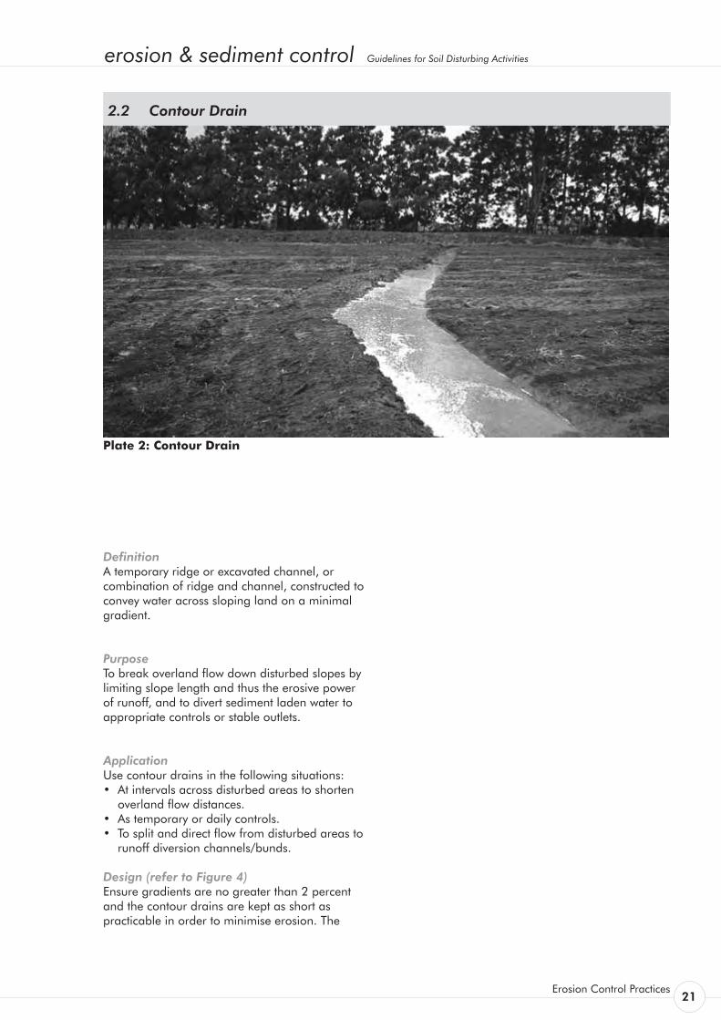
Definition A temporary ridge or excavated channel, or combination of ridge and channel, constructed to convey water across sloping land on a minimal gradient.
Purpose To break overland flow down disturbed slopes by limiting slope length and thus the erosive power of runoff, and to divert sediment laden water to appropriate controls or stable outlets.
Application Use contour drains in the following situations: • At intervals across disturbed areas to shorten
overland flow distances. • As temporary or daily controls. • To split and direct flow from disturbed areas to
runoff diversion channels/bunds.
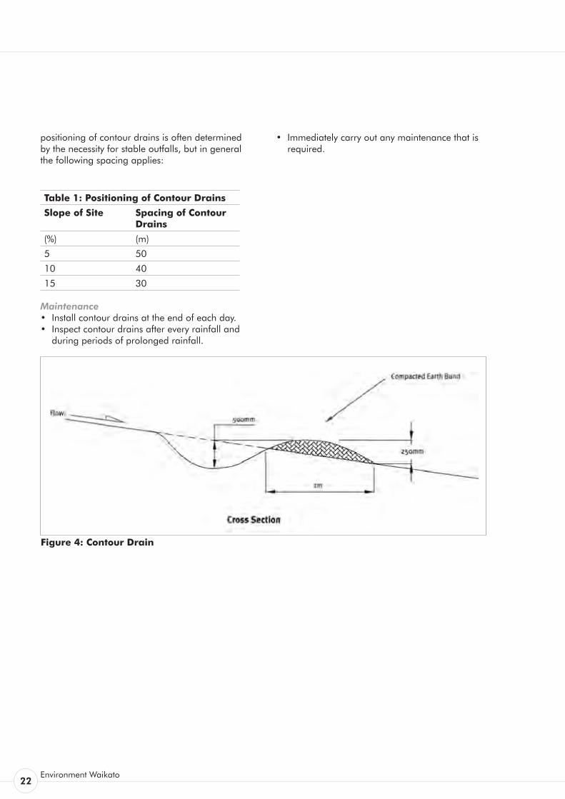
Design (refer to Figure 4) Ensure gradients are no greater than 2 percent and the contour drains are kept as short as practicable in order to minimise erosion. The
Contour Drain 2.2
Plate 2: Contour Drain
22Environment Waikato
positioning of contour drains is often determined by the necessity for stable outfalls, but in general the following spacing applies:
Table 1: Positioning of Contour Drains
Slope of Site Spacing of Contour Drains
(%) (m)
5 50
10 40
15 30
Maintenance • Install contour drains at the end of each day. • Inspect contour drains after every rainfall and
during periods of prolonged rainfall.
• Immediately carry out any maintenance that is required.
Figure 4: Contour Drain
erosion & sediment control Guidelines for Soil Disturbing Activities
Erosion Control Practices 23
Definition A channel excavated parallel to a road or track.
Purpose To provide permanent underfill drainage of the carriageway and/or to provide a conveyance channel for stormwater.
Application This practice applies primarily to permanent roading where it is necessary to provide a degree of underfill drainage of the carriageway to ensure road stability and/or where upslope storm flows and storm flows arising from the carriageway itself are required to be conveyed to an erosion proof outfall.
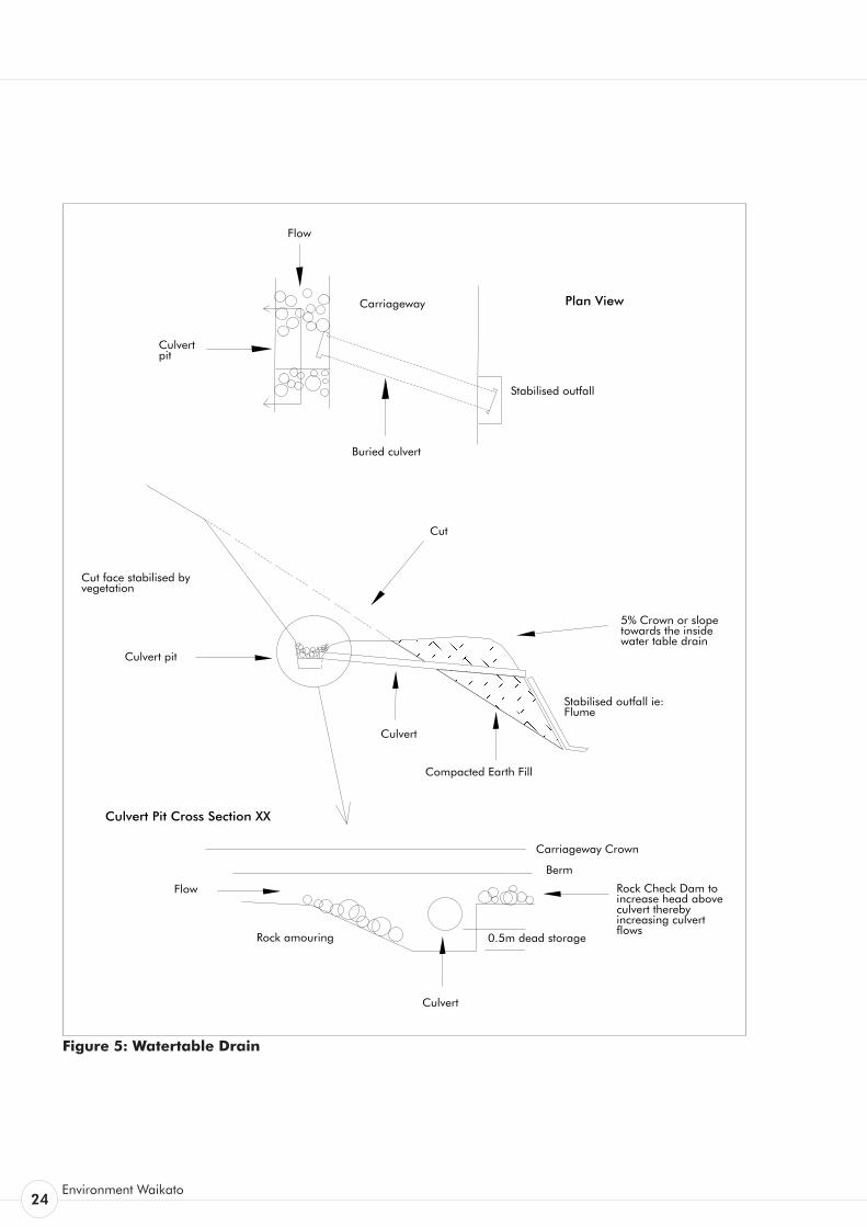
Design (refer to Figure 5) The following outlines design criteria requirements. • Design the watertable drain to carry the flow
from the critical 10 percent AEP rainfall event. • Watertable drains with greater than 2 percent
gradient may need to be armoured (refer Table 2).
Armouring is normally done with appropriately sized aggregate compacted into the invert of the drain and laid at an appropriate depth. Alternatives are site concrete and corrugated fluming or a series of check dams.
• Construct with a cross sectional shape with as large an invert width as practicable to minimise flow velocities - refer Figure 3.
• Position rock check dams along steep sections to provide additional armouring.
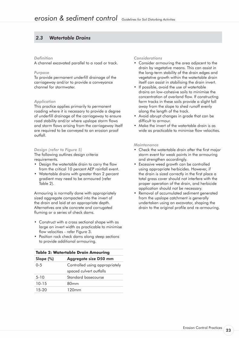
Table 2: Watertable Drain Amouring
Slope (%) Aggregate size D50 mm
0-5 Controlled using appropriately
spaced culvert outfalls
5-10 Standard basecourse
10-15 80mm
15-20 120mm
Considerations • Consider armouring the area adjacent to the
drain by vegetative means. This can assist in the long-term stability of the drain edges and vegetative growth within the watertable drain itself can assist in stabilising the drain invert.
• If possible, avoid the use of watertable drains on low-cohesive soils to minimise the concentration of overland flow. If constructing farm tracks in these soils provide a slight fall away from the slope to shed runoff evenly along the length of the track.
• Avoid abrupt changes in grade that can be difficult to armour.
• Make the invert of the watertable drain is as wide as practicable to minimise flow velocities.
Maintenance • Check the watertable drain after the first major
storm event for weak points in the armouring and strengthen accordingly.
• Excessive weed growth can be controlled using appropriate herbicides. However, if the drain is sized correctly in the first place a total grass cover should not interfere with the proper operation of the drain, and herbicide application should not be necessary.
• Removal of accumulated sediment generated from the upslope catchment is generally undertaken using an excavator, shaping the drain to the original profile and re-armouring.
Watertable Drains 2.3
24Environment Waikato
Compacted Earth Fill
Cut
5% Crown or slope towards the inside water table drain
Culvert
Stabilised outfall ie: Flume
Culvert pit
Cut face stabilised by vegetation
Carriageway
Buried culvert
Stabilised outfall
Flow
Culvert pit
Plan View
Culvert Pit Cross Section XX
Flow
0.5m dead storage
Culvert
Berm
Carriageway Crown
Rock amouring
Rock Check Dam to increase head above culvert thereby increasing culvert flows
Figure 5: Watertable Drain
erosion & sediment control Guidelines for Soil Disturbing Activities
Erosion Control Practices 25
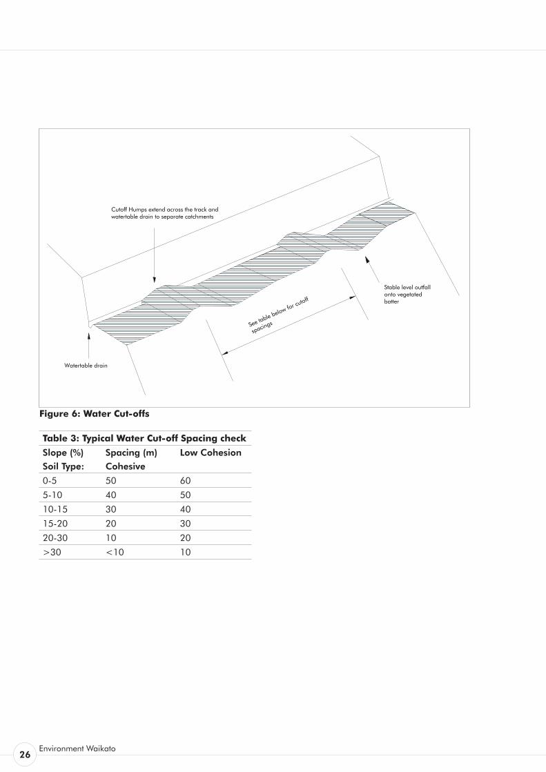
Definition An excavated channel combined with a compacted earth bund extending more or less at right angles across the carriageway and berm, to a stable outfall.
Purpose To provide temporary or permanent drainage of surface water off the carriageway at regular intervals to prevent the concentration of overland flow.
Application This practice applies primarily to low use roading and tracking where storm flows arising from upslope of the road and the carriageway itself are required to be conveyed to an erosion proof outfall.
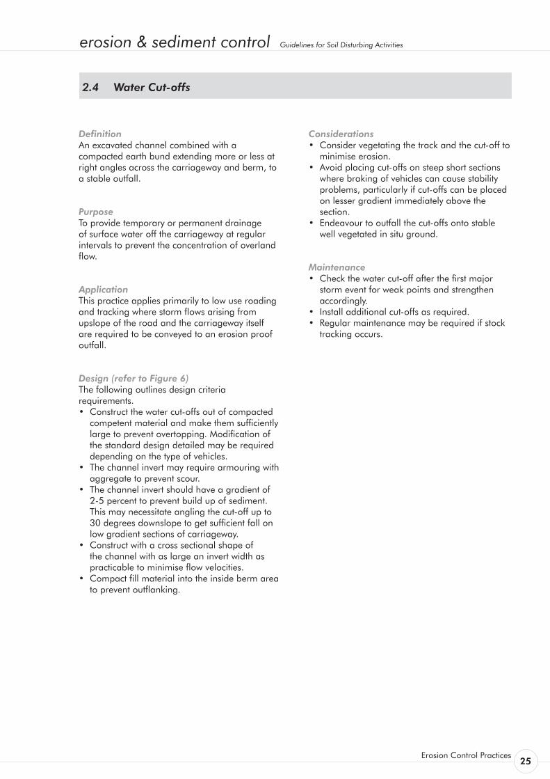
Design (refer to Figure 6) The following outlines design criteria requirements. • Construct the water cut-offs out of compacted
competent material and make them sufficiently large to prevent overtopping. Modification of the standard design detailed may be required depending on the type of vehicles.
• The channel invert may require armouring with aggregate to prevent scour.
• The channel invert should have a gradient of 2-5 percent to prevent build up of sediment.
This may necessitate angling the cut-off up to 30 degrees downslope to get sufficient fall on
low gradient sections of carriageway. • Construct with a cross sectional shape of
the channel with as large an invert width as practicable to minimise flow velocities.
• Compact fill material into the inside berm area to prevent outflanking.
Considerations • Consider vegetating the track and the cut-off to
minimise erosion. • Avoid placing cut-offs on steep short sections
where braking of vehicles can cause stability problems, particularly if cut-offs can be placed on lesser gradient immediately above the section.
• Endeavour to outfall the cut-offs onto stable well vegetated in situ ground.
Maintenance • Check the water cut-off after the first major
storm event for weak points and strengthen accordingly.
• Install additional cut-offs as required. • Regular maintenance may be required if stock
tracking occurs.
Water Cut-offs2.4
26Environment Waikato
Table 3: Typical Water Cut-off Spacing check
Slope (%)
Soil Type:
Spacing (m)
Cohesive
Low Cohesion
0-5 50 60
5-10 40 50
10-15 30 40
15-20 20 30
20-30 10 20
>30 <10 10
See table below for cutoff
spacings
Stable level outfall onto vegetated batter
Watertable drain
Cutoff Humps extend across the track and watertable drain to separate catchments
Water Cutoff Spacing
Slope% Spacing Cohesive soils Low cohesion soils0-5 5-10 10-15 15-20 20-30 >30
50 60 40 50 30 40 20 30 10 20 <10 10
Figure 6: Water Cut-offs
erosion & sediment control Guidelines for Soil Disturbing Activities
Erosion Control Practices 27
Definition A surface flow conveyance structure connecting the watertable drain to a stable outfall.
Purpose To provide a permanent flow conveyance structure under a carriageway.
Application This practice applies primarily to permanent roading where it is necessary to prevent the concentration of overland flow in the watertable drain by providing regular drainage points to an erosion proof outfall.
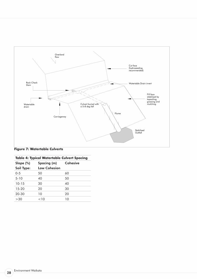
Design (refer to Figure 7) The following outlines design criteria requirements:
• Design the watertable culvert to carry the flow from the critical 10 percent AEP rainfall event. The efficiency of the culvert will depend on the inlet geometry so every effort should be made to ensure a smooth entry into the culvert inlet.
• Watertable culverts should be placed with a gradient of 5-8 percent to ensure self cleaning.
• Generally watertable culverts (pipes) should not be smaller than 300 mm diameter to minimise entrance blockage.
• A culvert pit up to 1m deep is generally constructed at the entrance to the watertable culvert. The culvert inlet should be about 0.5 m above the invert of this pit.
• The spacing of watertable culverts will depend on the surface area of the carriageway, the upslope catchment and the erodibility of the in situ soils. Spacing will also depend on the location of stable outfalls ie well vegetated spurs or ridges where flows can be dissipated.
• Consider constructing rock check dams in the watertable drain immediately below the culvert inlet to improve culvert inlet efficiency.
Considerations • Define stable outfall points and install culverts
to these points first. • If possible, avoid discharges to fill areas as
these will require armouring or drop structures. • Surface fluming (tanalised 150 x 50) can be
used on farm tracks however debris build-up is generally high, requiring regular maintenance.
• Grading a farm track to have a series of ‘hump and hollows’ can provide a low cost alternative to regularly spaced culverts.
• The increased gradient into the culvert pit.
Maintenance • Check the watertable culvert after the first
major storm event for blockage and the stability of the outfall.
• Check the culvert pit for sediment/debris and remove.
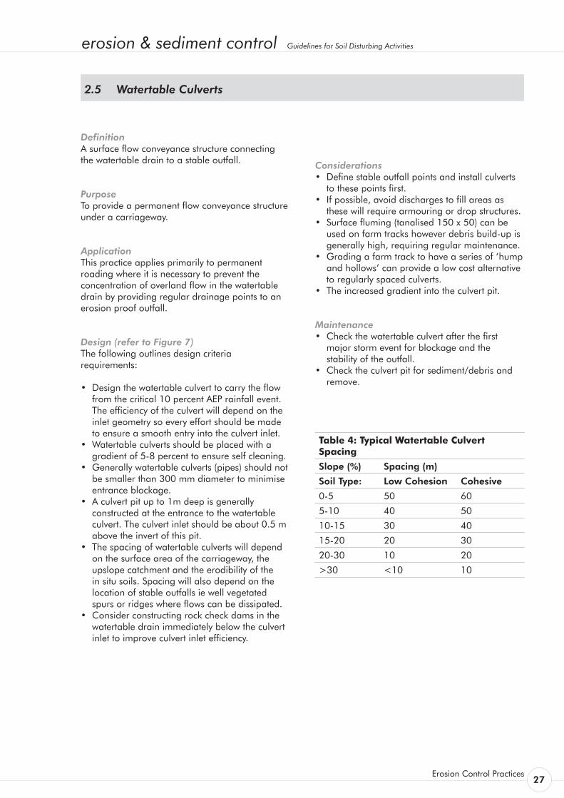
Table 4: Typical Watertable Culvert Spacing
Slope (%) Spacing (m)
Soil Type: Low Cohesion Cohesive
0-5 50 60
5-10 40 50
10-15 30 40
15-20 20 30
20-30 10 20
>30 <10 10
Watertable Culverts2.5
28Environment Waikato
Cut face(hydroseeding recommended)
Overland flow
Fill facestabilised by topsoiling, grassing and mulchingWatertable
drain
Flume
Culvert buried with a 5-8 deg fall
Carriageway
Stabilised Outfall
Rock Check Dam
Watertable Drain invert
Table 4: Typical Watertable Culvert Spacing
Slope (%)
Soil Type:
Spacing (m)
Low Cohesion
Cohesive
0-5 50 60
5-10 40 50
10-15 30 40
15-20 20 30
20-30 10 20
>30 <10 10
Figure 7: Watertable Culverts
erosion & sediment control Guidelines for Soil Disturbing Activities
Erosion Control Practices 29
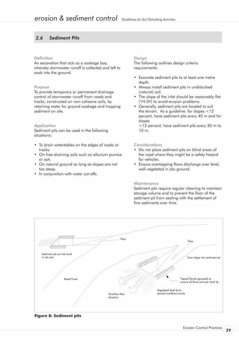
DefinitionAn excavation that acts as a soakage bay, whereby stormwater runoff is collected and left to soak into the ground.
PurposeTo provide temporary or permanent drainage control of stormwater runoff from roads and tracks, constructed on non-cohesive soils, by retaining water for ground soakage and trapping sediment on site.
ApplicationSediment pits can be used in the following situations:
• To drain watertables on the edges of roads or tracks.
• On free-draining soils such as alluvium pumice or ash.
• On natural ground as long as slopes are not too steep.
• In conjunction with water cut-offs.
DesignThe following outlines design criteria requirements:
• Excavate sediment pits to at least one metre depth.
• Always install sediment pits in undisturbed (natural) soil.
• The slope of the inlet should be reasonably flat (1H:5V) to avoid erosion problems.
• Generally, sediment pits are located to suit the terrain. As a guideline: for slopes <12 percent, have sediment pits every 40 m and for slopes
>12 percent, have sediment pits every 30 m to 10 m.
Considerations• Do not place sediment pits on blind areas of
the road where they might be a safety hazard for vehicles.
• Ensure overtopping flows discharge over level, well-vegetated in situ ground.
MaintenanceSediment pits require regular cleaning to maintain storage volume and to prevent the floor of the sediment pit from sealing with the settlement of fine sediments over time.
Figure 8: Sediment pits
Sediment Pits2.6

30Environment Waikato
erosion & sediment control Guidelines for Soil Disturbing Activities
Erosion Control Practices 31
Definition An aggregate bund constructed on the outside berm parallel to the carriageway.
Purpose To provide permanent diversion of stormwater away from erosion prone fill batters.
Application This practice applies primarily to permanent roading where it is necessary to direct carriageway runoff to an erosion proof outfall. It normally applies to the conveyance of flows along the berm of an inside bend, however can also be used effectively on both sides of a culvert crossing where carriageway flows tend to concentrate.
Design The following outlines design criteria requirements. • Design the berm bund to carry the flow from
the critical 10 percent AEP rainfall event. • Outfall flows to a level area of berm if possible
where flows can dissipate over a wide area.
Considerations If possible, avoid the use of berm bunds on low-cohesive soils to minimise the concentration of overland flow. If constructing farm tracks in these soils provide a slight fall away from the slope to shed runoff evenly along the length of the track.
Avoid abrupt changes in grade that can be difficult to armour.
Maintenance Check the berm bund after the first major storm event and periodically for weak points in the armouring and strengthen accordingly.
Berm bunds 2.7

32Environment Waikato
erosion & sediment control Guidelines for Soil Disturbing Activities
Erosion Control Practices 33
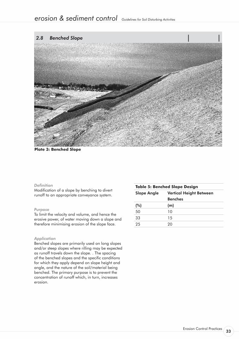
Definition Modification of a slope by benching to divert runoff to an appropriate conveyance system.
Purpose To limit the velocity and volume, and hence the erosive power, of water moving down a slope and therefore minimising erosion of the slope face.
Application Benched slopes are primarily used on long slopes and/or steep slopes where rilling may be expected as runoff travels down the slope. . The spacing of the benched slopes and the specific conditions for which they apply depend on slope height and angle, and the nature of the soil/material being benched. The primary purpose is to prevent the concentration of runoff which, in turn, increases erosion.
Benched Slope 2.8
Plate 3: Benched Slope
Table 5: Benched Slope Design
Slope Angle Vertical Height Between
Benches
(%) (m)
50 10
33 15
25 20
34Environment Waikato
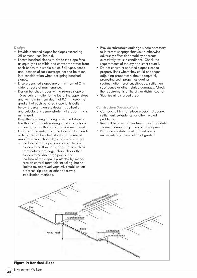
Design • Provide benched slopes for slopes exceeding 25 percent - see Table 5. • Locate benched slopes to divide the slope face
as equally as possible and convey the water from each bench to a stable outlet. Soil types, seeps and location of rock outcrops need to be taken into consideration when designing benched slopes.
• Ensure benched slopes are a minimum of 2 m wide for ease of maintenance.
• Design benched slopes with a reverse slope of 15 percent or flatter to the toe of the upper slope
and with a minimum depth of 0.3 m. Keep the gradient of each benched slope to its outlet below 2 percent, unless design, stabilisation and calculations demonstrate that erosion risk is minimised.
• Keep the flow length along a benched slope to less than 250 m unless design and calculations can demonstrate that erosion risk is minimised.
• Divert surface water from the face of all cut and/or fill slopes of benched slopes by the use of runoff diversion channels/bunds except where: - the face of the slope is not subject to any
concentrated flows of surface water such as from natural drainage, channels or other concentrated discharge points, and
- the face of the slope is protected by special erosion control materials including, but not limited to, approved vegetative stabilisation practices, rip-rap, or other approved stabilisation methods.
• Provide subsurface drainage where necessary to intercept seepage that would otherwise adversely affect slope stability or create excessively wet site conditions. Check the requirements of the city or district council.
• Do not construct benched slopes close to property lines where they could endanger adjoining properties without adequately protecting such properties against sedimentation, erosion, slippage, settlement, subsidence or other related damages. Check the requirements of the city or district council.
• Stabilise all disturbed areas.
Construction Specifications • Compact all fills to reduce erosion, slippage,
settlement, subsidence, or other related problems.
• Keep all benched slopes free of unconsolidated sediment during all phases of development.
• Permanently stabilise all graded areas immediately on completion of grading.
Figure 9: Benched Slope
erosion & sediment control Guidelines for Soil Disturbing Activities
Erosion Control Practices 35
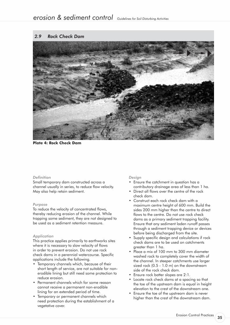
Plate 4: Rock Check Dam
Definition Small temporary dam constructed across a channel usually in series, to reduce flow velocity. May also help retain sediment.
Purpose To reduce the velocity of concentrated flows, thereby reducing erosion of the channel. While trapping some sediment, they are not designed to be used as a sediment retention measure.
Application This practice applies primarily to earthworks sites where it is necessary to slow velocity of flows in order to prevent erosion. Do not use rock check dams in a perennial watercourse. Specific applications include the following. • Temporary channels which, because of their
short length of service, are not suitable for non-erodible lining but still need some protection to reduce erosion.
• Permanent channels which for some reason cannot receive a permanent non-erodible lining for an extended period of time.
• Temporary or permanent channels which need protection during the establishment of a vegetative cover.
Rock Check Dam 2.9
Design • Ensure the catchment in question has a
contributory drainage area of less than 1 ha. • Direct all flows over the centre of the rock
check dam. • Construct each rock check dam with a
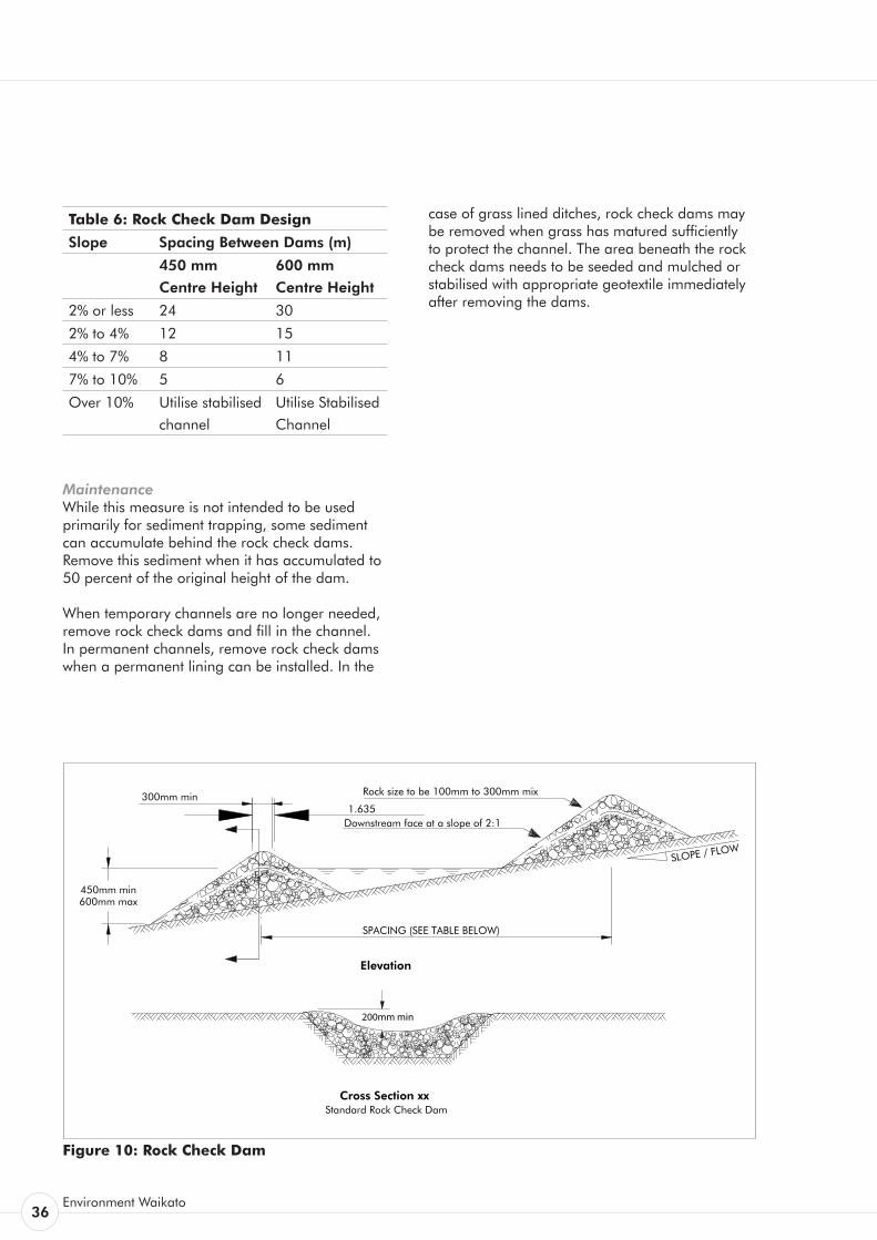
maximum centre height of 600 mm. Build the sides 200 mm higher than the centre to direct flows to the centre. Do not use rock check dams as a primary sediment trapping facility. Ensure that any sediment laden runoff passes through a sediment trapping device or devices before being discharged from the site.
• Supply specific design and calculations if rock check dams are to be used on catchments greater than 1 ha.
• Place a mix of 100 mm to 300 mm diameter washed rock to completely cover the width of the channel. In steeper catchments use larger sized rock (0.5 - 1.0 m) on the downstream side of the rock check dam.
• Ensure rock batter slopes are 2:1. • Locate rock check dams at a spacing so that
the toe of the upstream dam is equal in height elevation to the crest of the downstream one.
• Ensure the toe of the upstream dam is never higher than the crest of the downstream dam.
36Environment Waikato
Table 6: Rock Check Dam Design
Slope Spacing Between Dams (m)
450 mm
Centre Height
600 mm
Centre Height
2% or less 24 30
2% to 4% 12 15
4% to 7% 8 11
7% to 10% 5 6
Over 10% Utilise stabilised
channel
Utilise Stabilised
Channel
Maintenance While this measure is not intended to be used primarily for sediment trapping, some sediment can accumulate behind the rock check dams. Remove this sediment when it has accumulated to 50 percent of the original height of the dam.
When temporary channels are no longer needed, remove rock check dams and fill in the channel. In permanent channels, remove rock check dams when a permanent lining can be installed. In the
case of grass lined ditches, rock check dams may be removed when grass has matured sufficiently to protect the channel. The area beneath the rock check dams needs to be seeded and mulched or stabilised with appropriate geotextile immediately after removing the dams.
Figure 10: Rock Check Dam
1.635300mm min
450mm min600mm max
SPACING (SEE TABLE BELOW)
SLOPE / FLOW
Elevation
Cross Section xxStandard Rock Check Dam
Slope 2% or less 2% to 4% 4% to 7%
7% to 10% over 10%
Spacing (m) Between Dams(450mm centre height)
241285
Use Stabilised Channel
Spacing (m) Between Dams(600mm centre height)
3015116
Use Stabilised Channel
Downstream face at a slope of 2:1
Rock size to be 100mm to 300mm mix
200mm min
erosion & sediment control Guidelines for Soil Disturbing Activities
Erosion Control Practices 37
Definition The placement of topsoil over a prepared subsoil prior to the establishment of vegetation.
Purpose To provide a suitable soil medium for vegetative growth for erosion control while providing some limited short term erosion control capability by protecting subsoils and absorbing water.
Application Top soiling is recommended in the following situations:
• Where the texture and/or the organic component of the exposed subsoil or parent material can not produce adequate vegetative growth.
• Where the soil material is so shallow that the rooting zone is not deep enough to support plants or furnish continuing supplies of moisture and plant nutrients.
• Where high quality turf and landscape plantings are to be established.
Generally top soiling is combined with vegetation establishment and is not seen as an erosion control measure in itself. Top soiling as a short term stand alone erosion control measure is limited to sites with an average slope of less than 5 percent with contour drains installed as per these guidelines and for periods of less than two weeks only.
Top soiling alone will not provide sufficient erosion protection to allow sediment control measures to be removed.
When staging within an earthworks operation, top soiling as a treatment in itself is not acceptable and other means of stabilisation such as re-vegetation will also be required.
Design Not applicable.
Construction Specifications Once site shaping work has been completed, evenly spread a minimum of 100 mm of topsoil before re-vegetating. On steeper sites (over 25 percent), scarify the subsoils to a depth of a least 100 mm to ensure bonding between topsoil and subsoil before applying topsoil.
Incorporate surface roughening into all top soiling operations in accordance with these guidelines.
In general topsoil has a beneficial effect in light rain because it can hold more moisture than the underlying clay material. However, during heavy rain, topsoil will become saturated and rill erosion and slumping can result. For this reason it is important to establish a full vegetative cover as soon as possible and retain all sediment retention facilities on the site until a vegetative cover is fully established.
Maintenance Check the condition of the topsoil on a regular basis and re-grade and/or replace where necessary so as to always maintain the 100 mm minimum depth of topsoil and surface roughening.
Topsoil2.10

38Environment Waikato
erosion & sediment control Guidelines for Soil Disturbing Activities
Erosion Control Practices 39
Definition The planting and establishment of quick growing and/or perennial vegetation to provide temporary and/or permanent stabilisation on exposed areas.
Purpose Seeding is designed to stabilise soil on disturbed areas to reduce sediment and runoff to downstream or off-site areas.
Application • Seeding This practice applies to any site where
establishing vegetation is important to protect bare earth.
Design Not applicable.
Construction Specifications • SitePreparation Before seeding, install all required erosion and
sediment control practices such as diversion channels and sediment retention structures. Grade the site as necessary to permit the use of conventional equipment for soil preparation, seeding and maintenance.
• SeedBedPreparation Prepare a good seed bed to ensure successful
establishment of vegetation. Take care to ensure that the seed bed is free of large clods, rocks and other unsuitable material. Apply topsoil at a minimum depth of 100 mm to allow for a loose and friable soil surface.
• SoilAmendments Apply fertiliser as outlined in Table 7 of these
guidelines. This fertiliser application rate can be varied with the approval of Environment Waikato. For large sites or unusual site conditions it is advisable to have soil fertility tests done. Some soils may require the addition of lime to
improve pH.
• Seeding Apply seed at a mixture and rate as in Table
7 of these guidelines. This seeding rate can be varied with approval from Environment Waikato. Apply the seed uniformly and sow at the recommended rate. Seed that is broadcast must be covered by raking and then lightly compacted into place. If hydroseeding is required, then it can be utilised in accordance with Section 2 of these guidelines.
• Mulching When working on steep sites (greater than 20 percent) or during the winter period
(between May 1 and September 30) mulching will need to be applied in accordance with Section 2 of these guidelines immediately following seeding.
• Irrigation Adequate moisture is essential for seed
germination and plant growth. Irrigation can be very helpful in establishing vegetation during dry or hot weather conditions or on adverse site conditions. Irrigation must be carefully controlled to prevent runoff and subsequent erosion. Inadequate or excessive irrigation can do more harm than good.
Maintenance Re-seed where seed germination is unsatisfactory or where erosion occurs. In the event of unsatisfactory germination after May 1, the area will also require the application of mulch in accordance with Section 2 of these guidelines.
Depending on site conditions it may be necessary to irrigate, fertilise, oversow or re-establish plantings in order to provide vegetation for adequate erosion control. See Table 7 of these guidelines for details of maintenance fertiliser applications.
Protect all re-vegetated areas from traffic flows and other activities such as the installation of drainage lines and utility services.
Revegetation Techniques2.11
Seeding2.11.1

40Environment Waikato
Table 7: Grass Seed and Fertiliser Application Rates
Mix Rate (kg/ha)
Seeding types Perennial Ryegrass
Brown Top with a
Red/White Clover mix
Perennial - 90
Brown Top - 30
Clover - 30
Fertiliser Application
D.A.P. (Di-Ammonium Phosphate)
or similar
240
erosion & sediment control Guidelines for Soil Disturbing Activities
Erosion Control Practices 41
Definition The application of seed, fertiliser and paper or wood pulp with water in the form of a slurry, sprayed over the area to be re-vegetated.
Purpose To establish vegetation quickly while providing a degree of instant protection from raindrop impact.
Application This practice applies to any site where vegetation establishment is important for the protection of bare earth surfaces. For example:
• Critical areas on the site prone to erosion such as steep slopes and sediment retention pond batters.
• Critical areas on the site that cannot be stabilised by conventional sowing methods.
• Around watercourses or runoff diversion channels where rapid establishment of a protective vegetative cover is required before introducing flows.
Design Not applicable.
Construction Specifications The seed generally adheres to the pulp which improves the microclimate for germination and establishment. This method allows vegetation to establish on difficult sites and can extend into cooler winter months provided it is utilised with mulching.
• SitePreparation Before hydroseeding, install any needed
erosion and sediment control practices such as runoff diversion channels. Scarify any steep or smooth clay surfaces to improve retention of the hydroseeding slurry. Hydroseeding specifications need to be verified by Environment Waikato prior to implementation, with recommended seeding and fertiliser application rates outlined in Table 7 of these guidelines.
• Watering Hydroseeding requires moisture for
germination and growth. Because hydroseeding is often used for difficult sites, the timing of the application to get favourable growing conditions is an important factor.
• Maintenance Heavy rainfall can wash hydroseeding
away, particularly from smooth clay surfaces and overland flowpaths. Where vegetation establishment is unsatisfactory the area may require hydroseeding again. In the event of unsatisfactory germination after May 1, the area will also require mulching in accordance with Section 2 of these guidelines.
Protect all re-vegetated areas from traffic flows and other activities such as the installation of drainage lines and utility services.
Hydroseeding 2.11.2

42Environment Waikato
erosion & sediment control Guidelines for Soil Disturbing Activities
Erosion Control Practices 43
Definition The application of a protective layer of straw or other suitable material to the soil surface.
Purpose To protect the soil surface from the erosive forces of raindrop impact and overland flow. Mulching also helps to conserve moisture, reduce runoff and erosion, control weeds, prevent soil crusting and promote the establishment of desirable vegetation.
Application This practice applies to any site where vegetation establishment is important for the protection of bare earth surfaces. Mulching provides a microenvironment creating suitable conditions for germination and rapid growth.
Mulching can be used at any time where the instant protection of the soil surface is desired. Mulching can be used in conjunction with seeding to establish vegetation, or by itself to provide temporary protection of the soil surface.
Mulching is also used during the winter months to provide immediate stabilisation because grass
Mulching 2.11.3
germination will be too slow to establish effective grass cover using conventional sowing methods.
Design Not applicable.
Construction Specifications • SitePreparation Before mulching install any erosion and
sediment control practices such as runoff diversion channels and sediment retention structures.
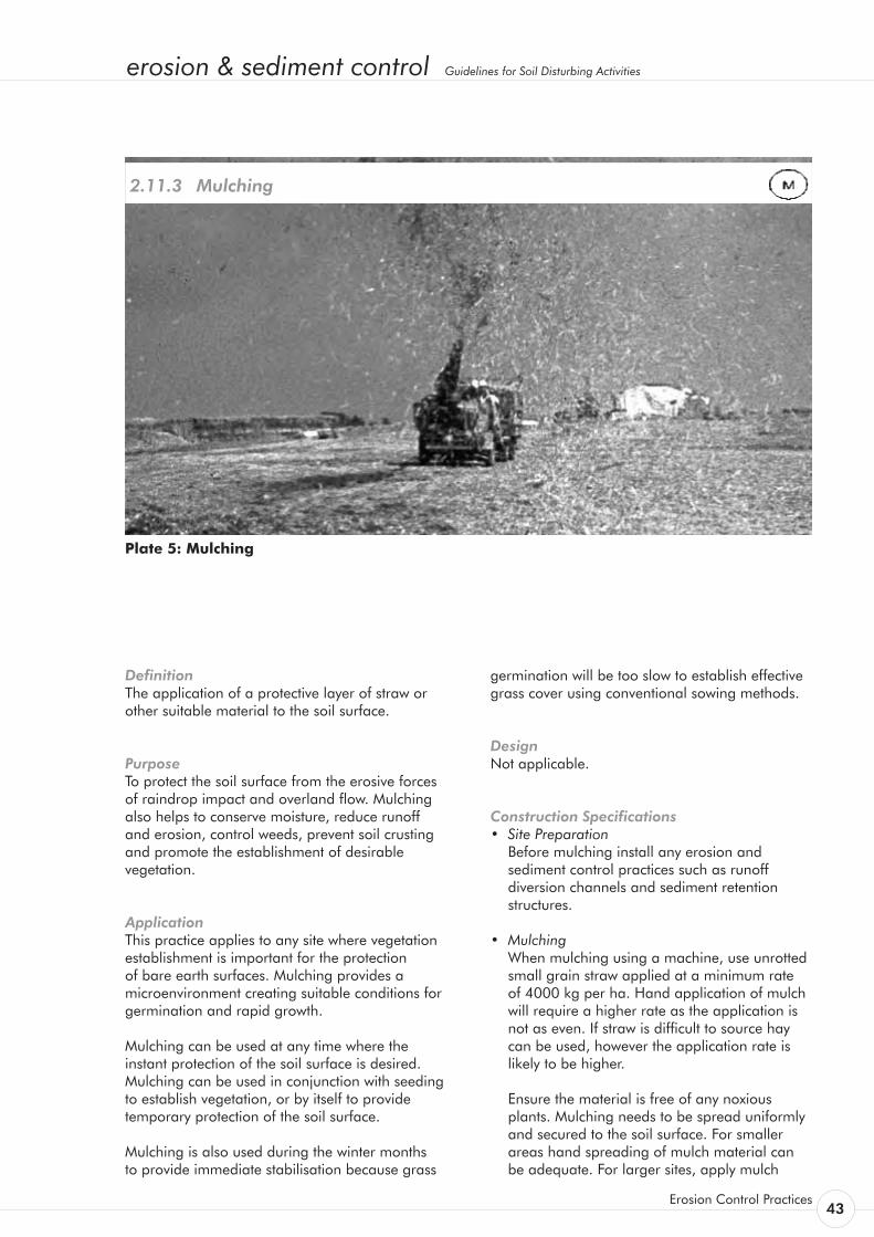
• Mulching When mulching using a machine, use unrotted
small grain straw applied at a minimum rate of 4000 kg per ha. Hand application of mulch will require a higher rate as the application is not as even. If straw is difficult to source hay can be used, however the application rate is likely to be higher.
Ensure the material is free of any noxious plants. Mulching needs to be spread uniformly and secured to the soil surface. For smaller areas hand spreading of mulch material can be adequate. For larger sites, apply mulch
Plate 5: Mulching
44Environment Waikato
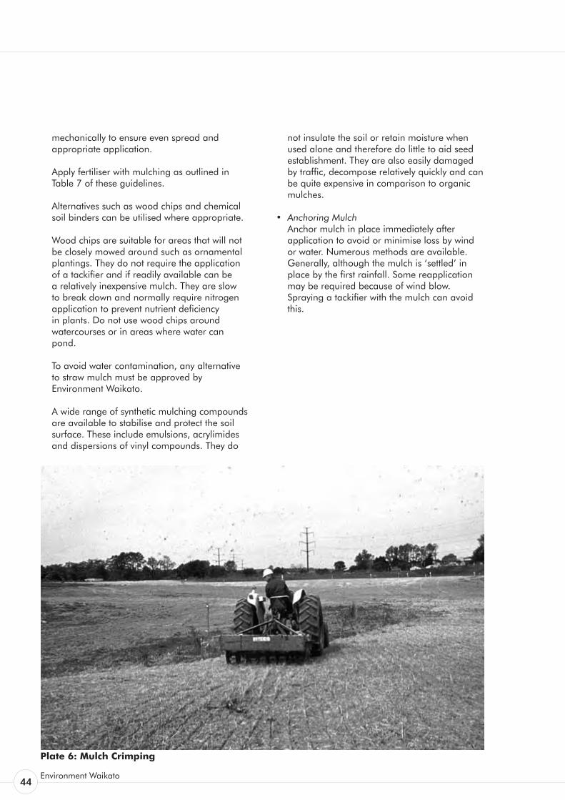
mechanically to ensure even spread and appropriate application.
Apply fertiliser with mulching as outlined in Table 7 of these guidelines.
Alternatives such as wood chips and chemical soil binders can be utilised where appropriate.
Wood chips are suitable for areas that will not be closely mowed around such as ornamental plantings. They do not require the application of a tackifier and if readily available can be a relatively inexpensive mulch. They are slow to break down and normally require nitrogen application to prevent nutrient deficiency in plants. Do not use wood chips around watercourses or in areas where water can pond.
To avoid water contamination, any alternative to straw mulch must be approved by
Environment Waikato.
A wide range of synthetic mulching compounds are available to stabilise and protect the soil surface. These include emulsions, acrylimides and dispersions of vinyl compounds. They do
not insulate the soil or retain moisture when used alone and therefore do little to aid seed establishment. They are also easily damaged by traffic, decompose relatively quickly and can be quite expensive in comparison to organic mulches.
• AnchoringMulch Anchor mulch in place immediately after
application to avoid or minimise loss by wind or water. Numerous methods are available. Generally, although the mulch is ‘settled’ in place by the first rainfall. Some reapplication may be required because of wind blow. Spraying a tackifier with the mulch can avoid this.
Plate 6: Mulch Crimping
erosion & sediment control Guidelines for Soil Disturbing Activities
Erosion Control Practices 45
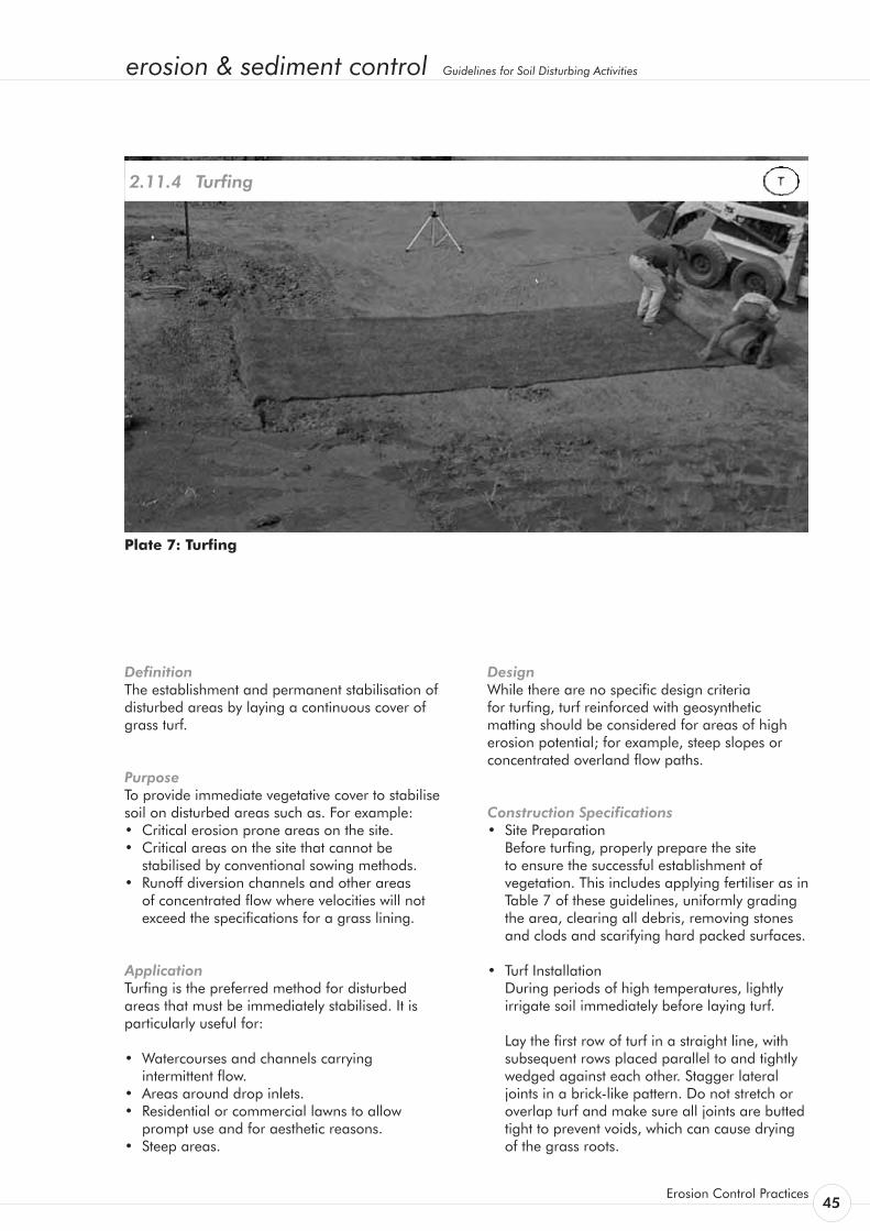
Definition The establishment and permanent stabilisation of disturbed areas by laying a continuous cover of grass turf.
Purpose To provide immediate vegetative cover to stabilise soil on disturbed areas such as. For example: • Critical erosion prone areas on the site. • Critical areas on the site that cannot be
stabilised by conventional sowing methods. • Runoff diversion channels and other areas
of concentrated flow where velocities will not exceed the specifications for a grass lining.
Application Turfing is the preferred method for disturbed areas that must be immediately stabilised. It is particularly useful for:
• Watercourses and channels carrying intermittent flow.
• Areas around drop inlets. • Residential or commercial lawns to allow
prompt use and for aesthetic reasons. • Steep areas.
Turfing 2.11.4
Design While there are no specific design criteria for turfing, turf reinforced with geosynthetic matting should be considered for areas of high erosion potential; for example, steep slopes or concentrated overland flow paths.
Construction Specifications • Site Preparation Before turfing, properly prepare the site
to ensure the successful establishment of vegetation. This includes applying fertiliser as in Table 7 of these guidelines, uniformly grading the area, clearing all debris, removing stones and clods and scarifying hard packed surfaces.
• Turf Installation During periods of high temperatures, lightly
irrigate soil immediately before laying turf.
Lay the first row of turf in a straight line, with subsequent rows placed parallel to and tightly wedged against each other. Stagger lateral joints in a brick-like pattern. Do not stretch or overlap turf and make sure all joints are butted tight to prevent voids, which can cause drying of the grass roots.
Plate 7: Turfing

46Environment Waikato
On sloping areas or channels where erosion may be a problem, lay turf downslope with the ends of the turf material overlapped such that the upslope turf overlaps the downslope turf by at least 100 mm. It may be necessary to secure the turf with pegs or staples. Ensure the turf at the top of the slope is appropriately trenched in to prevent runoff moving underneath it.
As turfing is completed in one area, roll or tamp the entire area to ensure solid contact of the grass roots with the soil surface. After rolling, immediately water the turf until the underside of the new turf and soil surface below the turf are thoroughly wet.
• Maintenance- Water daily during the first week of laying
unless there is adequate rainfall. - Do not mow the area until the turf is firmly
rooted. - Apply fertiliser regularly as in Table 7 of
these guidelines uniformly.
erosion & sediment control Guidelines for Soil Disturbing Activities
Erosion Control Practices 47
Definition The artificial protection of channels and erodible slopes utilising artificial erosion control material such as geosynthetic matting, geotextiles or erosion matting.
Purpose To immediately reduce the erosion potential of disturbed areas and/or to reduce or eliminate erosion on critical sites during the period necessary to establish protective vegetation. Some forms of artificial protection may also help to establish protective vegetation.
Application • On short steep slopes. • On areas that have highly erodible soils. • In situations where conventional mulches are of
limited effectiveness in withstanding high runoff velocities.
• In channels (both perennial and ephemeral) where the design flow is greater than in-situ soil can withstand.
• In areas where there is not enough room to install adequate sediment controls.
• In critical erosion-prone areas such as sediment retention pond outlet and inlet points.
• In areas that may be slow to establish an adequate permanent vegetative cover.
• In areas where the downstream environment is of high value and rapid stabilisation is needed.
Design There are two categories of GECS: temporary degradable and permanent non-degradable.
• TemporaryDegradableGECS These are used to prevent loss of seedbed
and to promote vegetation establishment where vegetation alone will be sufficient for site protection once established. Common temporary GECS are erosion control blankets, open weave meshes/matting and organic erosion control netting (fibre mats factory bonded to synthetic netting).
• PermanentNon-DegradableGECS These are used to extend the erosion control
limits of vegetation, soil, rock or other materials. Common permanent GECS are three-dimensional erosion control and re-vegetation mats, geocellular confinement systems, reno mattresses and gabions.
Geosynthetic Erosion Control Systems (GECS) 2.12
The selection of an appropriate GECS is a complex balancing of the relative importance of the following requirements. • Endurance: durability, degree of resistance to
deformation over time and ultraviolet radiation and to chemicals (natural or as pollutants).
• Physical: thickness, weight, specific gravity and degree of light penetration. Generally a thicker, heavier material will provide better protection.
• Hydraulic: ability of the system to resist tractive shear strength and protect against channel erosion, erosion of underlying soils or slope erosion from rainfall impact.
• Mechanical: deformation and strength behaviour. Tensile strength and elongation, stiffness (how well it will conform to the subgrade) and how well it will resist tractive shear forces.
When a geotextile is to be used for temporary channel or spillway protection, consider combining a high strength, low permeability cloth over a soft pliable needle punch cloth pinned to ensure the cloth is in contact with the entire soil surface. Trench and pin all flow entry points such that the upslope geotextile edge overlaps the downslope geotextile mat. Toe in the upslope end of the downslope mat.
In high risk areas such as spillways and diversions, pin geotextiles down on a 0.5 m grid or in accordance with the manufacturers’ specifications, whichever provides the greatest number of contact points.
There is a large number of products available for all situations and depending on the degree of protection needed, a product or combination of products will be available to suit the situation. It is vital that the product used is designed for the intended use and installed and maintained according to its specifications. Consideration in using the various GECS available should be used based on the following characteristics: • sediment yield (generally ranked highest) • stability under flow • vegetation enhancement • durability • cost.
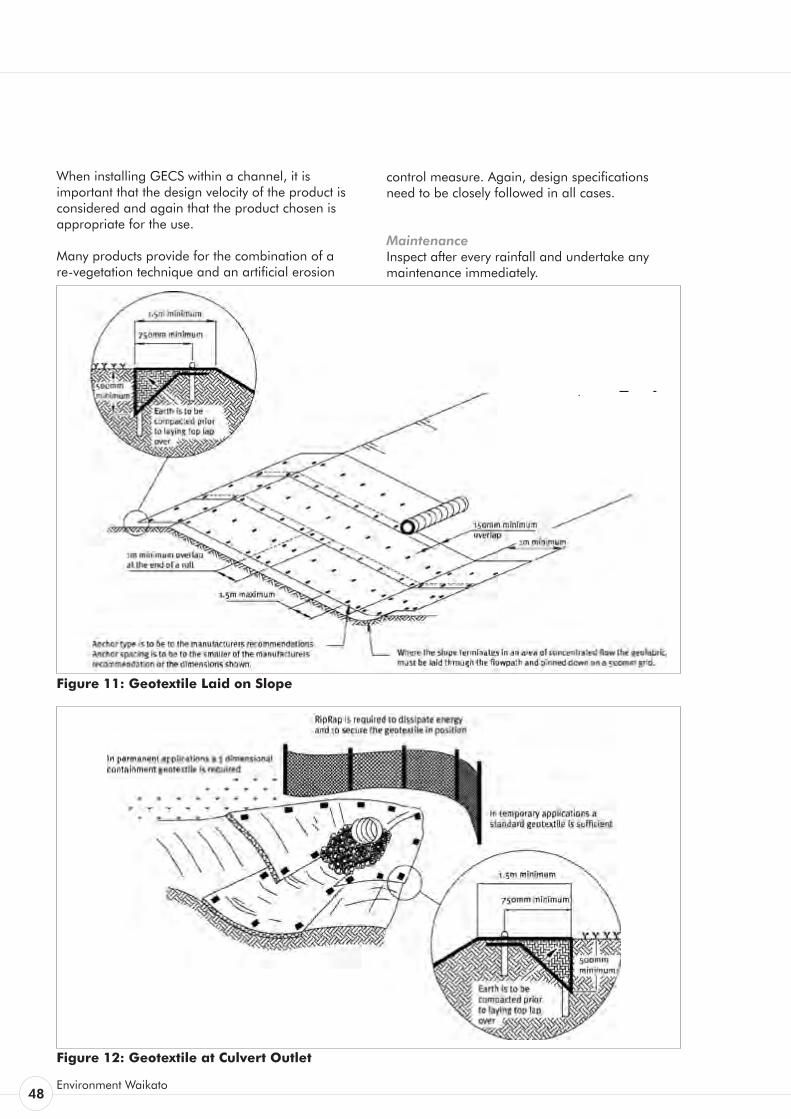
48Environment Waikato
When installing GECS within a channel, it is important that the design velocity of the product is considered and again that the product chosen is appropriate for the use.
Many products provide for the combination of a re-vegetation technique and an artificial erosion
control measure. Again, design specifications need to be closely followed in all cases.
Maintenance Inspect after every rainfall and undertake any maintenance immediately.
Figure 11: Geotextile Laid on Slope
Figure 12: Geotextile at Culvert Outlet
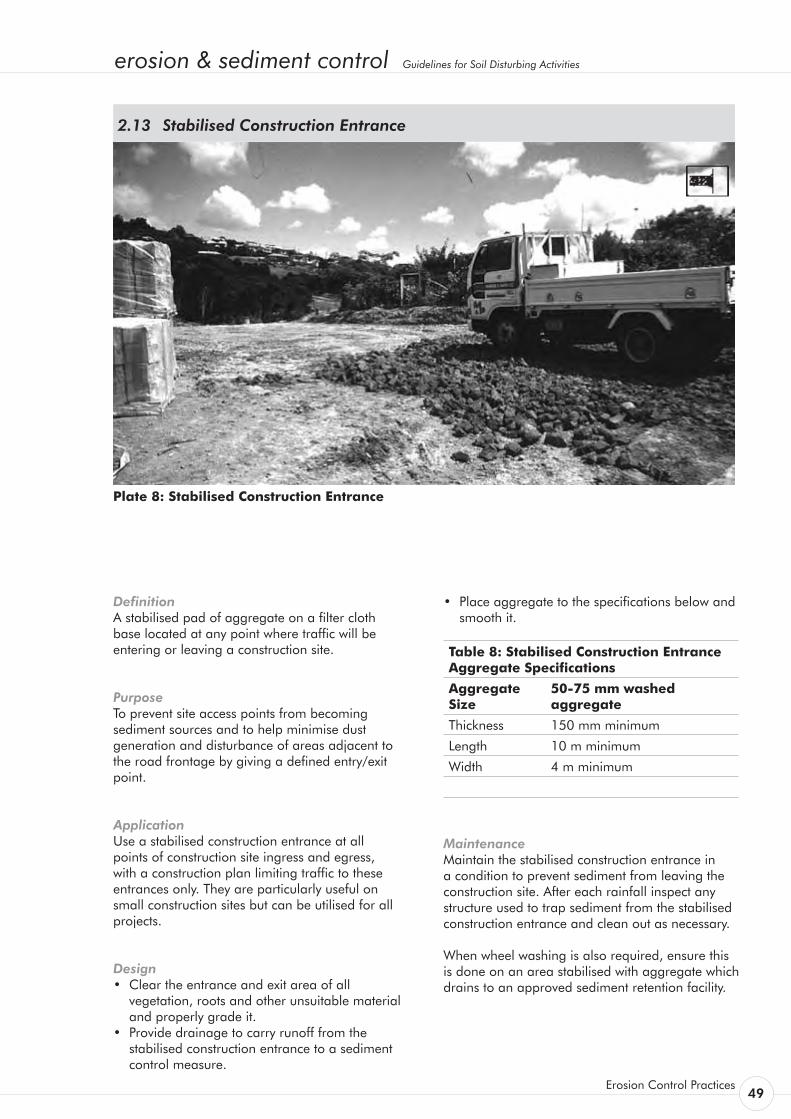
erosion & sediment control Guidelines for Soil Disturbing Activities
Erosion Control Practices 49
Definition A stabilised pad of aggregate on a filter cloth base located at any point where traffic will be entering or leaving a construction site.
Purpose To prevent site access points from becoming sediment sources and to help minimise dust generation and disturbance of areas adjacent to the road frontage by giving a defined entry/exit point.
Application Use a stabilised construction entrance at all points of construction site ingress and egress, with a construction plan limiting traffic to these entrances only. They are particularly useful on small construction sites but can be utilised for all projects.
Design • Clear the entrance and exit area of all
vegetation, roots and other unsuitable material and properly grade it.
• Provide drainage to carry runoff from the stabilised construction entrance to a sediment control measure.
Stabilised Construction Entrance 2.13
• Place aggregate to the specifications below and smooth it.
Table 8: Stabilised Construction Entrance Aggregate Specifications
Aggregate Size
50-75 mm washed aggregate
Thickness 150 mm minimum
Length 10 m minimum
Width 4 m minimum
Maintenance Maintain the stabilised construction entrance in a condition to prevent sediment from leaving the construction site. After each rainfall inspect any structure used to trap sediment from the stabilised construction entrance and clean out as necessary.
When wheel washing is also required, ensure this is done on an area stabilised with aggregate which drains to an approved sediment retention facility.
Plate 8: Stabilised Construction Entrance
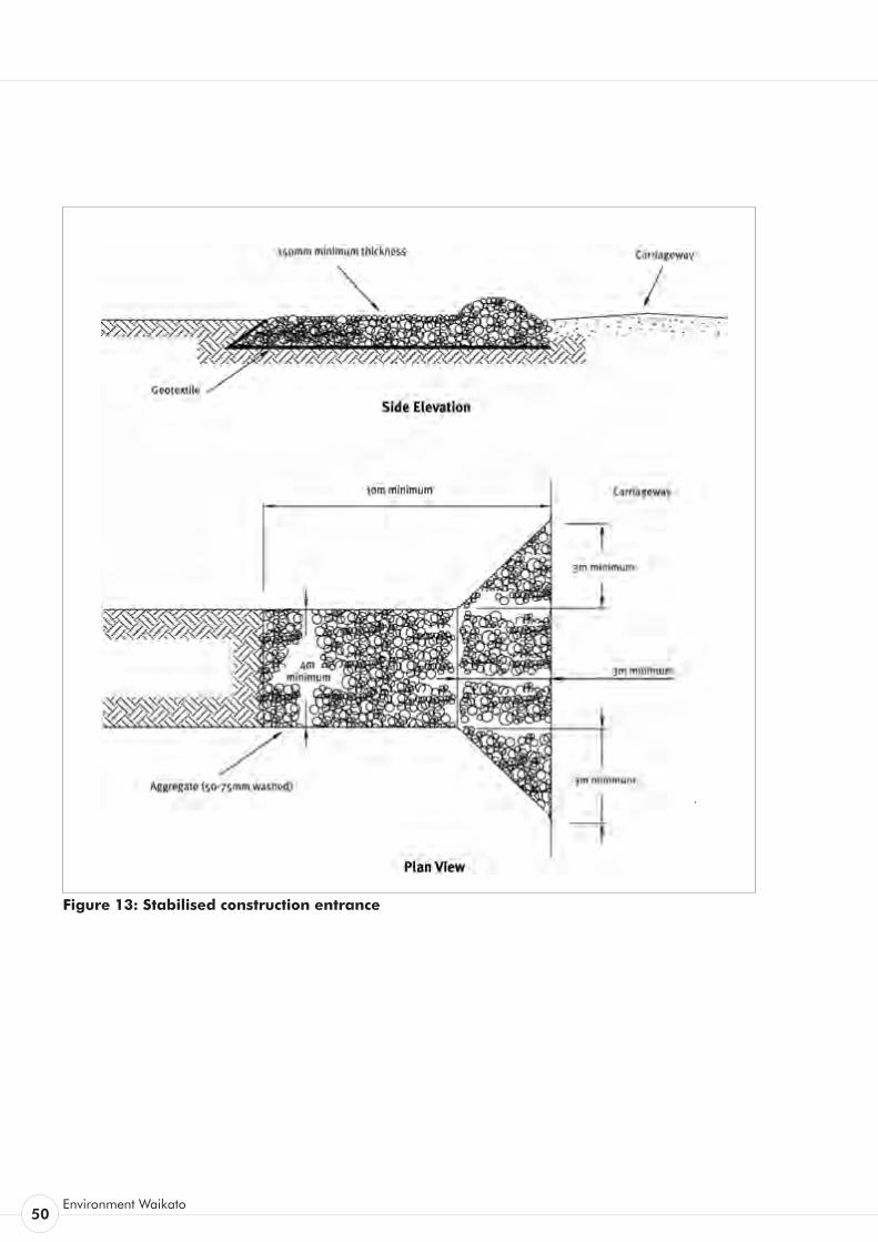
50Environment Waikato
Figure 13: Stabilised construction entrance
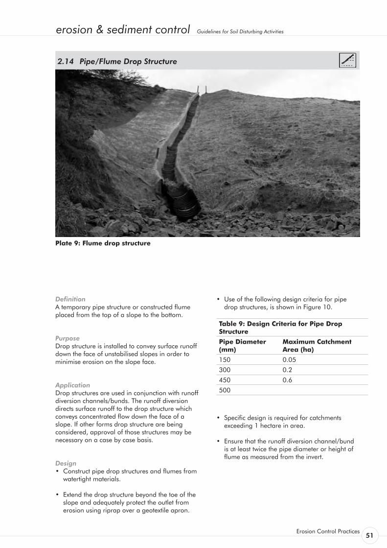
erosion & sediment control Guidelines for Soil Disturbing Activities
Erosion Control Practices 51
Definition A temporary pipe structure or constructed flume placed from the top of a slope to the bottom.
Purpose Drop structure is installed to convey surface runoff down the face of unstabilised slopes in order to minimise erosion on the slope face.
Application Drop structures are used in conjunction with runoff diversion channels/bunds. The runoff diversion directs surface runoff to the drop structure which conveys concentrated flow down the face of a slope. If other forms drop structure are being considered, approval of those structures may be necessary on a case by case basis.
Design • Construct pipe drop structures and flumes from
watertight materials.
• Extend the drop structure beyond the toe of the slope and adequately protect the outlet from erosion using riprap over a geotextile apron.
Pipe/Flume Drop Structure 2.14
• Use of the following design criteria for pipe drop structures, is shown in Figure 10.
Table 9: Design Criteria for Pipe Drop Structure
Pipe Diameter (mm)
Maximum Catchment Area (ha)
150 0.05
300 0.2
450 0.6
500
• Specific design is required for catchments exceeding 1 hectare in area.
• Ensure that the runoff diversion channel/bund is at least twice the pipe diameter or height of flume as measured from the invert.
Plate 9: Flume drop structure
52Environment Waikato
• Install a flared entrance section of compacted earth. To prevent erosion, place impermeable geotextile fabric into the inlet extended a minimum of 1.0 m in front of and to the side of the inlet and up the sides of the flared entrance. Ensure this geotextile is keyed 150 mm into the ground along all edges and pinned at 500 mm centres.
• When the catchment area is disturbed, ensure
the drop structure discharges into a sediment retention pond or a stable conveyance system that leads to a pond. When the catchment area is stabilised, ensure the drop structure outlets onto a stabilised area at a non-erosive velocity. The point of discharge may be protected by rock riprap.
• Ensure the drop structure has a minimum slope of 3 percent.
Construction Specifications for Pipe Drop Structures • A common cause of failure of pipe drop
structures is water saturating the soil and seeping along the pipe where it connects to the runoff diversion channel/bund. Backfill properly around and under the pipe with stable material in order to achieve firm contact between the pipe and the soil at all points to eliminate this type of failure. Pipe material used for the drop structure can consist of rigid pipe material or flexible pipe as required. If flexible pipe material is utilised, it is vital that the material be fixed to the slope at regular intervals to prevent movement. Rigid pipe can generally be secured at greater intervals.
• Place pipe drop structures on undisturbed soil or well-compacted fill at locations as detailed within the Erosion and Sediment Control Plan for the site.
• Immediately stabilise all disturbed areas following construction.
• Secure the Pipe drop structure to the slope at least every 4 m. Use no less than two anchors
equally spaced along the length of the pipe.
• Ensure all pipe connections are watertight.
Construction Specifications for flumes • A common failure of flumes is outflanking
of the flume entrance or scouring of the invert to the flume. This can be prevented by waterproofing the entrance to the flume by trenching in an appropriate impervious geotextile or plastic liner so that all flows are channelled directly into the flume. Alternatively a piped entrance can be installed.
• Flumes can be constructed from materials such as corrugated steel, construction ply, sawn timber or halved plastic piping.
• Construct the flume to ensure there are no leaks. For wooden or plywood flumes, or flumes where leakage is likely, extend an impervious liner down the full length of the flume structure.
• For slopes greater than 30 percent, a flume can be constructed from a standard 1.2 m x 2.4 m x 22 mm plywood sheet (refer to Figure 14). This will be adequate for catchments up to one hectare. Specific design is required for larger catchments.
• Fasten the flume to the slope using waratahs or wooden stakes placed in pairs down the slope at 1 - 4 m spacings depending on the flume material used. Fasten the flume to the waratahs or stakes using wire or steel strappings.
• Place flumes on undisturbed soil or well compacted fill at locations detailed in the site’s Erosion and Sediment Control Plan.
Maintenance • Inspect the pipe/flume drop structure
periodically and after each rain event. Immediately carry out any maintenance required.
• Keep the inlet open at all times.
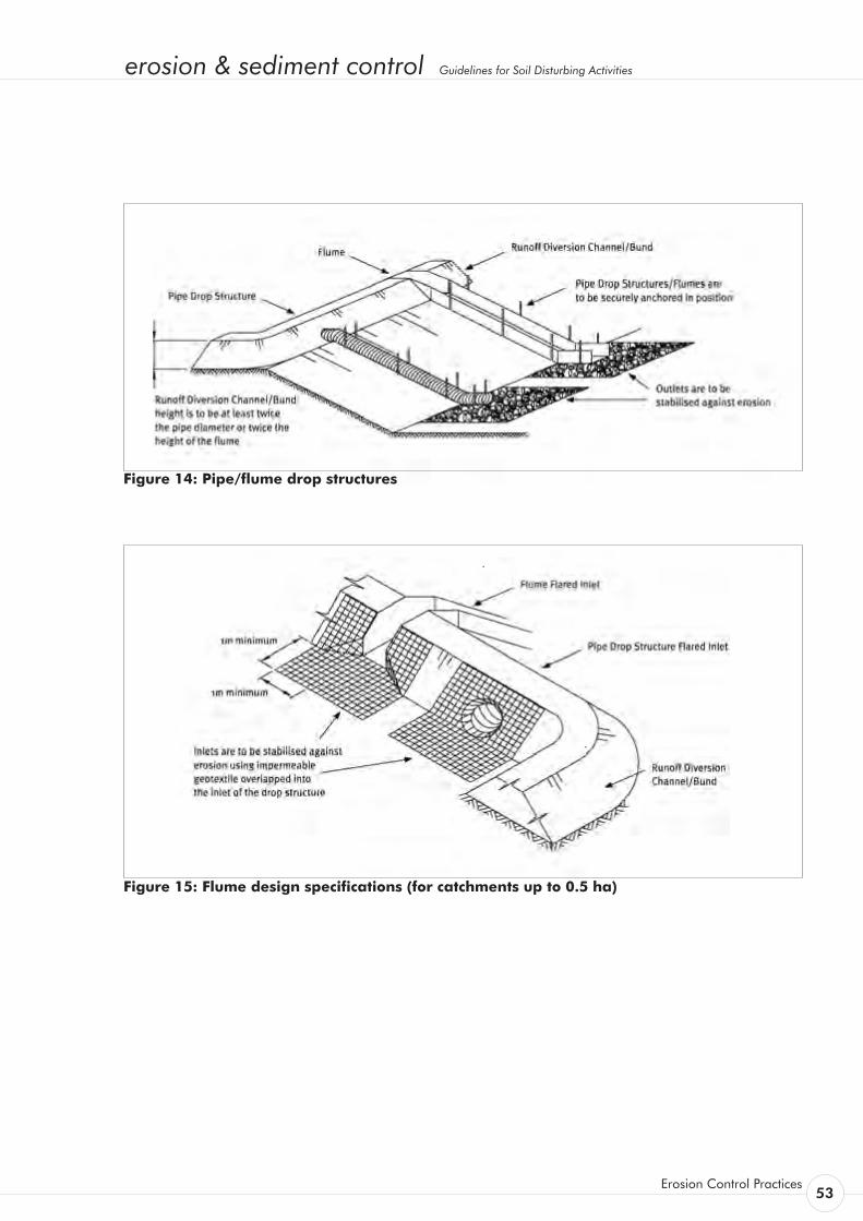
erosion & sediment control Guidelines for Soil Disturbing Activities
Erosion Control Practices 53
Figure 14: Pipe/flume drop structures
Figure 15: Flume design specifications (for catchments up to 0.5 ha)

54Environment Waikato
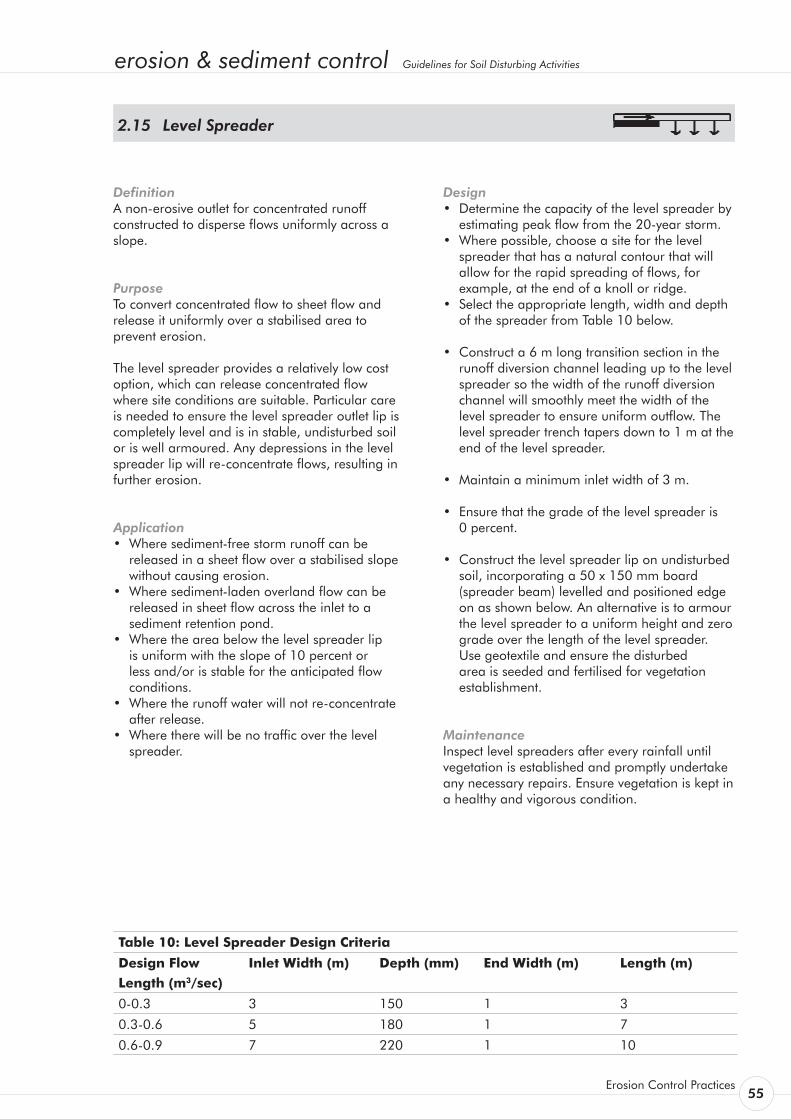
erosion & sediment control Guidelines for Soil Disturbing Activities
Erosion Control Practices 55
Definition A non-erosive outlet for concentrated runoff constructed to disperse flows uniformly across a slope.
Purpose To convert concentrated flow to sheet flow and release it uniformly over a stabilised area to prevent erosion.
The level spreader provides a relatively low cost option, which can release concentrated flow where site conditions are suitable. Particular care is needed to ensure the level spreader outlet lip is completely level and is in stable, undisturbed soil or is well armoured. Any depressions in the level spreader lip will re-concentrate flows, resulting in further erosion.
Application • Where sediment-free storm runoff can be
released in a sheet flow over a stabilised slope without causing erosion.
• Where sediment-laden overland flow can be released in sheet flow across the inlet to a sediment retention pond.
• Where the area below the level spreader lip is uniform with the slope of 10 percent or less and/or is stable for the anticipated flow conditions.
• Where the runoff water will not re-concentrate after release.
• Where there will be no traffic over the level spreader.
Level Spreader 2.15
Design • Determine the capacity of the level spreader by
estimating peak flow from the 20-year storm. • Where possible, choose a site for the level
spreader that has a natural contour that will allow for the rapid spreading of flows, for example, at the end of a knoll or ridge.
• Select the appropriate length, width and depth of the spreader from Table 10 below.
• Construct a 6 m long transition section in the runoff diversion channel leading up to the level spreader so the width of the runoff diversion channel will smoothly meet the width of the level spreader to ensure uniform outflow. The level spreader trench tapers down to 1 m at the end of the level spreader.
• Maintain a minimum inlet width of 3 m.
• Ensure that the grade of the level spreader is 0 percent.
• Construct the level spreader lip on undisturbed soil, incorporating a 50 x 150 mm board (spreader beam) levelled and positioned edge on as shown below. An alternative is to armour the level spreader to a uniform height and zero grade over the length of the level spreader. Use geotextile and ensure the disturbed area is seeded and fertilised for vegetation establishment.
Maintenance Inspect level spreaders after every rainfall until vegetation is established and promptly undertake any necessary repairs. Ensure vegetation is kept in a healthy and vigorous condition.
Table 10: Level Spreader Design Criteria
Design Flow Length (m3/sec)
Inlet Width (m) Depth (mm) End Width (m) Length (m)
0-0.3 3 150 1 3
0.3-0.6 5 180 1 7
0.6-0.9 7 220 1 10
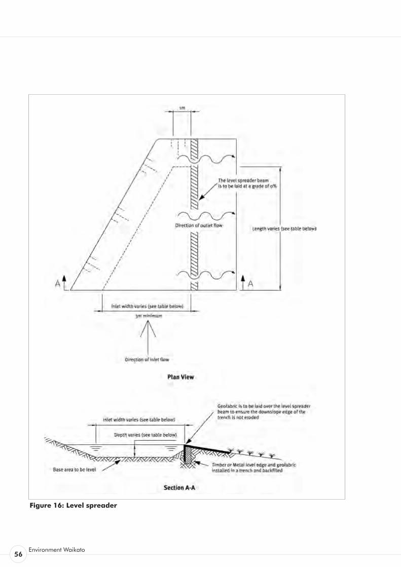
56Environment Waikato
Figure 16: Level spreader
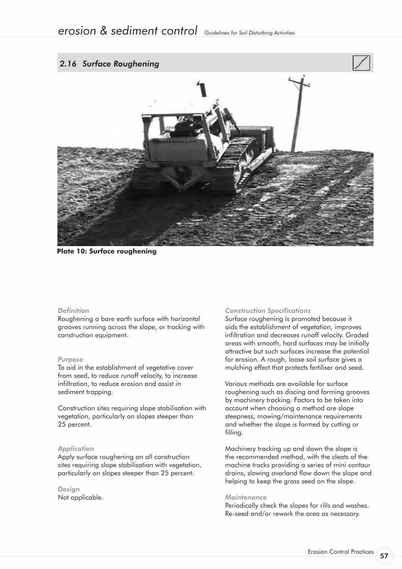
erosion & sediment control Guidelines for Soil Disturbing Activities
Erosion Control Practices 57
Definition Roughening a bare earth surface with horizontal grooves running across the slope, or tracking with construction equipment.
Purpose To aid in the establishment of vegetative cover from seed, to reduce runoff velocity, to increase infiltration, to reduce erosion and assist in sediment trapping.
Construction sites requiring slope stabilisation with vegetation, particularly on slopes steeper than 25 percent.
Application Apply surface roughening on all construction sites requiring slope stabilisation with vegetation, particularly on slopes steeper than 25 percent.
Design Not applicable.
Surface Roughening 2.16
Construction Specifications Surface roughening is promoted because it aids the establishment of vegetation, improves infiltration and decreases runoff velocity. Graded areas with smooth, hard surfaces may be initially attractive but such surfaces increase the potential for erosion. A rough, loose soil surface gives a mulching effect that protects fertiliser and seed.
Various methods are available for surface roughening such as discing and forming grooves by machinery tracking. Factors to be taken into account when choosing a method are slope steepness, mowing/maintenance requirements and whether the slope is formed by cutting or filling.
Machinery tracking up and down the slope is the recommended method, with the cleats of the machine tracks providing a series of mini contour drains, slowing overland flow down the slope and helping to keep the grass seed on the slope.
Maintenance Periodically check the slopes for rills and washes. Re-seed and/or rework the area as necessary.
Plate 10: Surface roughening
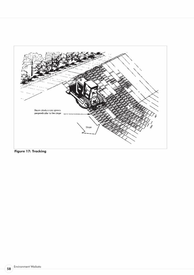
58Environment Waikato
Figure 17: Tracking


erosion & sediment control Guidelines for Soil Disturbing Activities
Sediment Control Practices 59
Sediment Control Practices3.

60Environment Waikato
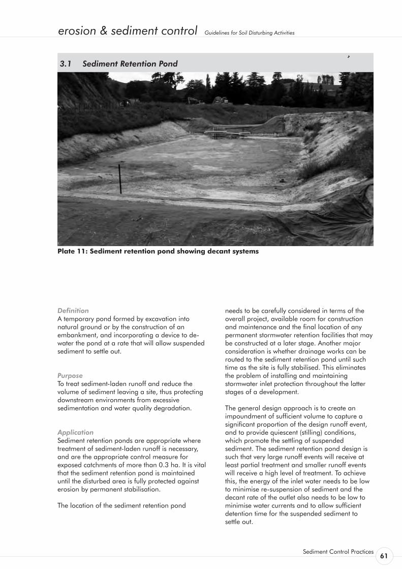
erosion & sediment control Guidelines for Soil Disturbing Activities
Sediment Control Practices 61
Definition A temporary pond formed by excavation into natural ground or by the construction of an embankment, and incorporating a device to de-water the pond at a rate that will allow suspended sediment to settle out.
Purpose To treat sediment-laden runoff and reduce the volume of sediment leaving a site, thus protecting downstream environments from excessive sedimentation and water quality degradation.
Application Sediment retention ponds are appropriate where treatment of sediment-laden runoff is necessary, and are the appropriate control measure for exposed catchments of more than 0.3 ha. It is vital that the sediment retention pond is maintained until the disturbed area is fully protected against erosion by permanent stabilisation.
The location of the sediment retention pond
Sediment Retention Pond 3.1
Plate 11: Sediment retention pond showing decant systems
needs to be carefully considered in terms of the overall project, available room for construction and maintenance and the final location of any permanent stormwater retention facilities that may be constructed at a later stage. Another major consideration is whether drainage works can be routed to the sediment retention pond until such time as the site is fully stabilised. This eliminates the problem of installing and maintaining stormwater inlet protection throughout the latter stages of a development.
The general design approach is to create an impoundment of sufficient volume to capture a significant proportion of the design runoff event, and to provide quiescent (stilling) conditions, which promote the settling of suspended sediment. The sediment retention pond design is such that very large runoff events will receive at least partial treatment and smaller runoff events will receive a high level of treatment. To achieve this, the energy of the inlet water needs to be low to minimise re-suspension of sediment and the decant rate of the outlet also needs to be low to minimise water currents and to allow sufficient detention time for the suspended sediment to settle out.
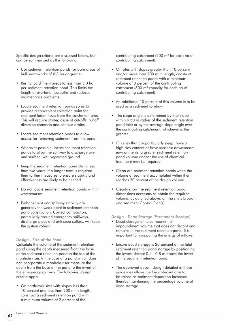
62Environment Waikato
Specific design criteria are discussed below, but can be summarised as the following.
• Use sediment retention ponds for bare areas of bulk earthworks of 0.3 ha or greater.
• Restrict catchment areas to less than 5.0 ha per sediment retention pond. This limits the length of overland flowpaths and reduces maintenance problems.
• Locate sediment retention ponds so as to provide a convenient collection point for sediment laden flows from the catchment area. This will require strategic use of cut-offs, runoff diversion channels and contour drains.
• Locate sediment retention ponds to allow access for removing sediment from the pond.
• Wherever possible, locate sediment retention ponds to allow the spillway to discharge over undisturbed, well vegetated ground.
• Keep the sediment retention pond life to less than two years. If a longer term is required then further measures to ensure stability and effectiveness are likely to be needed.
• Do not locate sediment retention ponds within watercourses.
• Embankment and spillway stability are generally the weak point in sediment retention pond construction. Correct compaction, particularly around emergency spillways, discharge pipes and anti seep collars, will keep the system robust.
Design - Size of the Pond Calculate the volume of the sediment retention pond using the depth measured from the base of the sediment retention pond to the top of the manhole riser. In the case of a pond which does not incorporate a manhole riser measure the depth from the base of the pond to the invert of the emergency spillway. The following design criteria apply.
• On earthwork sites with slopes less than 10 percent and less than 200 m in length,
construct a sediment retention pond with a minimum volume of 2 percent of the
contributing catchment (200 m3 for each ha of contributing catchment).
• On sites with slopes greater than 10 percent and/or more than 200 m in length, construct sediment retention ponds with a minimum volume of 3 percent of the contributing catchment (300 m3 capacity for each ha of contributing catchment).
• An additional 10 percent of this volume is to be used as a sediment forebay.
• The slope angle is determined by that slope within a 50 m radius of the sediment retention pond inlet or by the average slope angle over the contributing catchment, whichever is the greater.
• On sites that are particularly steep, have a high clay content or have sensitive downstream environments, a greater sediment retention pond volume and/or the use of chemical treatment may be required.
• Clean out sediment retention ponds when the volume of sediment accumulated within them reaches 20 percent of the design volume.
• Clearly show the sediment retention pond dimensions necessary to obtain the required volume, as detailed above, on the site’s Erosion and sediment Control Plan(s).
Design - Dead Storage (Permanent Storage) • Dead storage is the component of
impoundment volume that does not decant and remains in the sediment retention pond. It is important for dissipating the energy of inflows.
• Ensure dead storage is 30 percent of the total sediment retention pond storage by positioning the lowest decant 0.4 - 0.8 m above the invert of the sediment retention pond.
• The approved decant design detailed in these guidelines allows the lower decant arm to be raised as sediment deposition increases, thereby maintaining the percentage volume of dead storage.
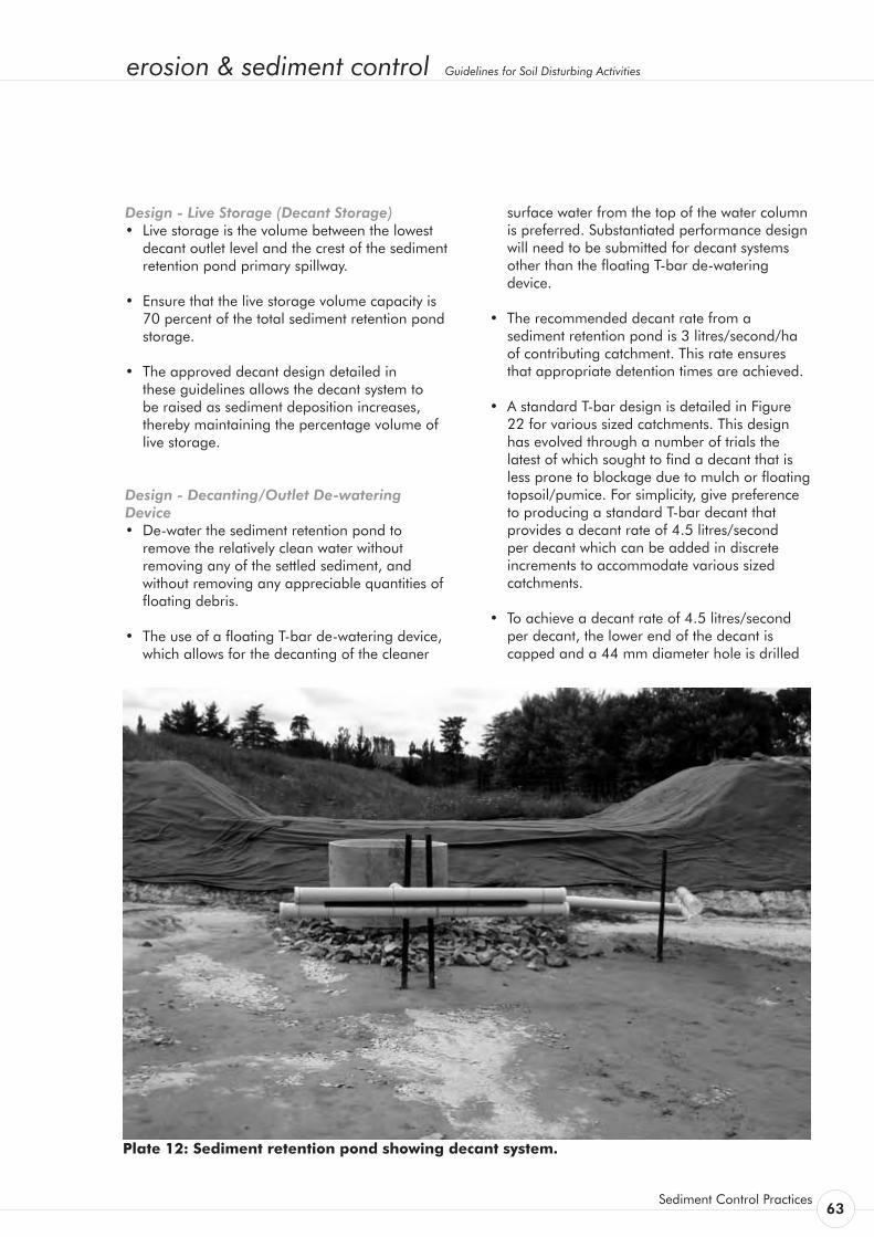
erosion & sediment control Guidelines for Soil Disturbing Activities
Sediment Control Practices 63
Design - Live Storage (Decant Storage) • Live storage is the volume between the lowest
decant outlet level and the crest of the sediment retention pond primary spillway.
• Ensure that the live storage volume capacity is 70 percent of the total sediment retention pond storage.
• The approved decant design detailed in these guidelines allows the decant system to be raised as sediment deposition increases, thereby maintaining the percentage volume of live storage.
Design - Decanting/Outlet De-watering Device • De-water the sediment retention pond to
remove the relatively clean water without removing any of the settled sediment, and without removing any appreciable quantities of floating debris.
• The use of a floating T-bar de-watering device, which allows for the decanting of the cleaner
surface water from the top of the water column is preferred. Substantiated performance design will need to be submitted for decant systems other than the floating T-bar de-watering device.
• The recommended decant rate from a sediment retention pond is 3 litres/second/ha of contributing catchment. This rate ensures that appropriate detention times are achieved.
• A standard T-bar design is detailed in Figure 22 for various sized catchments. This design has evolved through a number of trials the latest of which sought to find a decant that is less prone to blockage due to mulch or floating topsoil/pumice. For simplicity, give preference to producing a standard T-bar decant that provides a decant rate of 4.5 litres/second per decant which can be added in discrete increments to accommodate various sized catchments.
• To achieve a decant rate of 4.5 litres/second per decant, the lower end of the decant is capped and a 44 mm diameter hole is drilled
Plate 12: Sediment retention pond showing decant system.
64Environment Waikato
in the centre of the cap. Slots at 10 mm centres using a 4 mm wide cut-off blade are made along the full length of the decant. These slots extend a third of the way into the pipe.
• For catchments less than 1.5 ha in area the following hole sizes apply.
0.5 ha - 25 mm diameter 1.0 ha - 32 mm diameter
Alternatively the original decant design of 200 10 mm diameter holes positioned evenly over the decant can be used by blocking up the appropriate no of holes as required. Block out 65 holes if a decant rate of 3 l/sec is required. This design however, is prone to blockage.
• Single T-bar decants must be able to operate through the full live storage depth of the sediment retention pond.
• If two decant systems are required, ensure the lower T-bar decant operates through the full live storage depth of the sediment retention pond. The upper T-bar decant is to operate through the upper 50 percent of the live storage depth of the sediment retention pond only.
• If three decant systems are to be used, then the lower T-bar decant operates through the full live storage depth and the second T-bar decant through the upper two thirds of live storage depth of the sediment retention pond. The upper T-bar decant operates through the upper one third of live storage depth of the sediment retention pond as detailed in Figure 21. Although this arrangement reduces the decant rate per ha for the larger ponds, this is preferable to having separate decanting rates for each T-bar.
• Ensure that the T-bar decant float is securely fastened with steel strapping directly on top of the decant arm and weight it to keep the decant arm submerged just below the surface through all stages of the decant cycle. This will also minimise the potential for blockage of the decant slots by floating debris. The most successful method found to date is to weight the decant arm by strapping a 1.8 m long waratah between the float and the decant (approximately 4 kg of weight).
• Position the T-bar decant at the correct height by supporting the decant arm between warratahs as detailed in Figure 22.
• Lay the discharge pipe at a 1 - 2 percent gradient, compact the fill material around it using a machine compactor and incorporate anti-seep collars with the following criteria:
• Install collars around the pipe to increase the seepage length along the pipe with a spacing of approximately 10 m.
• The vertical projection of each collar is 1 m; ensure all anti seep collars and their connections are watertight.
• Use a flexible thick rubber coupling to provide a connection between the decant arm and the primary spillway or discharge pipe. To provide sufficient flexibility (such as is required for the lower decant arm) install two couplings. Fasten the flexible coupling using strap clamps and glue.
• Where a concrete riser decant system is utilised, ensure the lower decant connection is positioned on an angle upwards from the horizontal so as to split the operational angle that the decant works through. This will reduce the deformation force on the coupling used.
Design - Forebay • Construct a forebay with a volume equal to 10 percent of the pond design volume. On sites
with slopes less than 10 percent and lengths less than 200 m this equates to a forebay volume of 0.2 percent of the contributing catchment area - 0.2 m3 per 100 m2 of contributing catchment. On sites with slopes greater than 10 percent and lengths greater than 200 m, forebay volume is equivalent to 0.3 percent of the contributing catchment area ie: 0.3 m3 per 100 m2 of contributing catchment.
• The forebay is to extend the full width of the main pond and is to be 0.5 to 1 m deep.
• Inlets into the forebay are to be stabilised.
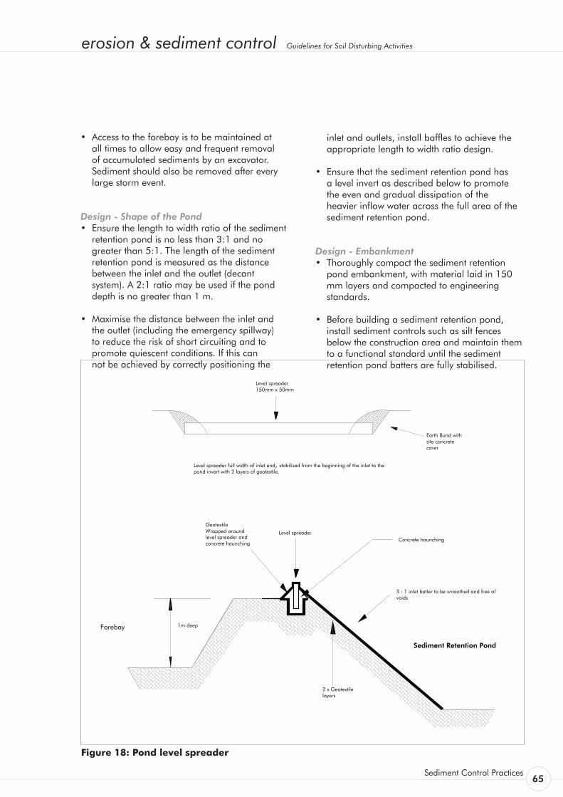
erosion & sediment control Guidelines for Soil Disturbing Activities
Sediment Control Practices 65
• Access to the forebay is to be maintained at all times to allow easy and frequent removal of accumulated sediments by an excavator. Sediment should also be removed after every large storm event.
Design - Shape of the Pond • Ensure the length to width ratio of the sediment
retention pond is no less than 3:1 and no greater than 5:1. The length of the sediment retention pond is measured as the distance between the inlet and the outlet (decant system). A 2:1 ratio may be used if the pond depth is no greater than 1 m.
• Maximise the distance between the inlet and the outlet (including the emergency spillway) to reduce the risk of short circuiting and to promote quiescent conditions. If this can not be achieved by correctly positioning the
inlet and outlets, install baffles to achieve the appropriate length to width ratio design.
• Ensure that the sediment retention pond has a level invert as described below to promote the even and gradual dissipation of the heavier inflow water across the full area of the sediment retention pond.
Design - Embankment • Thoroughly compact the sediment retention
pond embankment, with material laid in 150 mm layers and compacted to engineering standards.
• Before building a sediment retention pond, install sediment controls such as silt fences below the construction area and maintain them to a functional standard until the sediment retention pond batters are fully stabilised.
Figure 18: Pond level spreader
66Environment Waikato
• Where possible, install the discharge pipes through the embankment as the embankment is being constructed.
• Fully stabilise the external batter face, by vegetative or other means immediately after construction.
• Ensure all bare areas associated with the sediment retention pond (including internal batters) are stabilised with vegetation if the sediment retention pond is to remain in use
over winter.
Design - Pond Level Spreader • Incorporate a pond level spreader between the
forebay and the main pond to spread inflow velocities, thereby allowing rapid dissipation of inflow energies. Combine the pond level spreader with a well compacted and smoothed inlet batter (no steeper than a 3:1 gradient), stabilised over its entire area. The essential design feature is to ensure the pond level spreader is completely level, non-erodible and spans the full width of the sediment retention pond.
• Stabilise the level spreader and inlet embankment to the base of the pond with a layer of strong woven low permeability geotextile overlaid with a layer of soft non-woven needle punched geotextile. Pin at 500 mm centres.
• To ensure even inflows, install a trenched and pegged 150 mm x 50 mm timber weir or similar across the full width of the inlet. Bund the edges with compacted earth to prevent outflanking. This timber weir is haunched using site concrete which also serves to toe in the geotextile protection which will be required.
• Position the top of the pond level spreader weir 100 – 200 mm above the invert of the emergency spillway.
Design - Baffles • Incorporate baffles in the sediment retention
pond design where the recommended pond shape cannot be achieved. Extend baffles the full depth of the sediment retention pond and place them to maximise dissipation of flow energy.
• Generally, baffles are in the form of a wing to direct inflows away from the outlet and maximise the stilling zone. A series of compartments within the pond can be used to achieve this, although care must be taken to avoid creating in-pond currents and re-suspension of light particulates.
• Baffles may be constructed from various materials ranging from solid shutter boards to braced geotextile curtains.
Design - Depth of Pond • Sediment retention pond depths may be
1 - 2 m deep, but no deeper than 2 m. Deeper ponds are more likely to cause short circuiting problems during larger storm events and require specifically designed floating decant systems.
• The decant design in these guidelines operates through a maximum live storage range of
1.5 m.
Design - Primary Spillway • For larger catchments (greater than 1.5 ha) the
sediment retention pond requires a primary piped spillway (refer Figures).
• For catchments up to 1.5 ha, decant flows can be piped using the same diameter pipe as the decant system (100 mm PVC smooth bore) directly through the sediment retention pond wall to discharge beyond the toe of the sediment retention pond wall.
• For contributing catchments between 1.5 and 3 ha in area, use a discharge and primary
spillway pipe diameter of 150 mm.
• Where contributing catchments are 3 ha or greater and/or the long term stability of the sediment retention pond emergency spillway is questionable (for example, built in fill), then consideration must be given to incorporating a concrete manhole riser and larger diameter outlet pipe as a primary spillway sufficient to accommodate the 5 percent AEP rainfall event.
• If the sediment retention pond is to operate over the winter and the contributing catchment is fully stabilised, disconnect the T-bar decant to reduce the frequency of emergency spillway activation and consequent erosion.
erosion & sediment control Guidelines for Soil Disturbing Activities
Sediment Control Practices 67
• Where a primary spillway upstand riser is used, place the top of the riser a minimum 600 mm lower than the top of the sediment retention pond embankment and a minimum 300 mm lower than the emergency spillway crest. Ensure the riser and the discharge pipe connections are all completely watertight.
Design - Emergency Spillway • An emergency spillway is essential for all
sediment retention ponds.
• Emergency spillways must be capable of accommodating the 1 percent AEP event without eroding.
• Emergency spillways must discharge onto
stabilised ground. The emergency spillway must be located at the outlet end of the pond behind or beside the decant system.
• The emergency spillway crest and outer batter requires a very high standard of stabilisation with the fill material well compacted.
• Construct the emergency spillway as a stabilised trapezoidal cross section with a minimum bottom width of 4 m or the width of the pond floor, whichever is the greater up to a maximum width of 8 m. The trapezoidal cross sections to be continued down the outside batter to avoid flows outflanking the geotextile.
• When utilising geotextile for emergency spillway stabilisation purposes, the batter face must be smooth and all voids filled.
• If geotextile is used, a strong woven low permeability geotextile is laid first and then covered with a soft non-woven needle punched geotextile. Ensure the geotextile is pinned at
0.5 m centres over the full area of the emergency spillway.
• Where possible, construct emergency spillways in well vegetated, undisturbed ground (not fill) and discharge over long grass.
• If the emergency spillway is constructed on exposed soil, provide complete erosion protection by means such as grouted riprap, asphalt, erosion matting/geotextile or concrete.
• Construct the emergency spillway with a minimum of 300 mm freeboard height above the primary spillway invert.
Construction Specifications • Construct a fabric silt fence across the
downslope end of the proposed works.
• Clear areas under proposed fills of topsoil or other unsuitable material down to competent material. Large fill embankments may need to be keyed in.
• Use only approved fill.
• Place and compact fill in layers as per the engineer’s specifications.
• Do not place pervious materials such as sand or gravel within the fill material.
• Construct fill embankments approximately 10 percent higher than the design height to
allow for settlement of the material. Install appropriate pipe work and anti-seep collars during the construction of the embankment and compact around these appropriately.
• Install and stabilise the emergency spillway.
• Install and stabilise the level spreader.
• Securely attach the decant system to the horizontal pipework. Make all connections watertight. Place any manhole riser on a firm foundation of impervious soil.
• Do not place pervious material such as sand or scoria around the discharge pipe or the anti-seep collars.
• Install baffles if required.
• Check sediment retention pond freeboard for differential settlement and rectify as necessary.
• Stabilise both internal and external batters with vegetation.

68Environment Waikato
Pond Maintenance and Disposal of Sediment • Clean out sediment retention ponds before the
volume of accumulated sediment reaches 20 percent of the total sediment retention pond
volume. To assist in gauging sediment loads, clearly mark the 20 percent volume height on the decant riser.
• Clean out sediment retention ponds with high capacity sludge pumps, or with excavators (long reach excavators if needed) loading onto sealed tip trucks or to a secure area immediately adjacent to the pond.
• The Erosion and Sediment Control Plan should identify disposal locations for the sediment removed from the sediment retention pond. Deposit the sediment in such a location so that it does not lead to a direct discharge to receiving environments. Stabilise all disposal sites as required and approved in the site’s Erosion and Sediment Control Plan.
• Inspect sediment retention ponds every day and before every forecasted rainfall event. Inspect for correct operation after every runoff event. Immediately repair any damage to sediment retention ponds caused by erosion or construction equipment.
Safety Sediment retention ponds are attractive to children and can become safety hazards if not appropriately fenced and if safety rules are not followed. Low gradient pond batters provide an additional safety measure. Check the safety requirements of the City or District Council authority and the Occupational Safety and Health branch of the Department of Labour.
Chemical Treatment Some chemicals can be used successfully to promote flocculation (clumping together) of suspended solids in the sediment retention pond to increase the particle mass and speed the rate of settling.
Recent trials have identified a simple and effective chemical dosing system that does not require a power supply. This system uses poly aluminium chloride (PAC) and has been found to be particularly effective in settling fine particulate such as fine silts and clays. Other chemicals may become available as more trial data is obtained.
Chemical dosing systems are likely to be required where the design sediment retention pond volume cannot be achieved because of site constraints and/or where a high level of treatment is required because of the sensitivity of the receiving environment. Chemical treatment is also more likely to be required where the clay component is high.
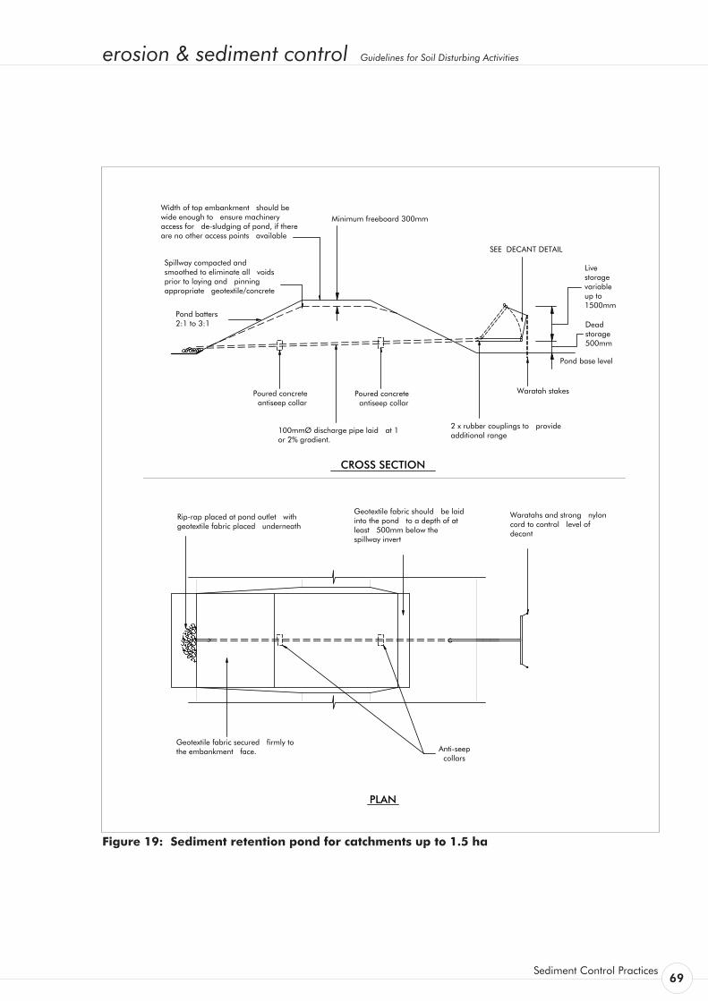
erosion & sediment control Guidelines for Soil Disturbing Activities
Sediment Control Practices 69
Single decantfor catchments up to 1.5 hectares
CROSS SECTION
PLANTP90_11.dwg
100mmØ discharge pipe laid at 1 or 2% gradient.
Minimum freeboard 300mm
Live storage variable up to 1500mm
Dead storage 500mm
Waratah stakes
Pond base level
SEE DECANT DETAIL
Poured concrete antiseep collar
Poured concrete antiseep collar
Waratahs and strong nylon cord to control level of decant
Anti-seep collars
Geotextile fabric secured firmly to the embankment face.
Rip-rap placed at pond outlet with geotextile fabric placed underneath
Pond batters 2:1 to 3:1
Spillway compacted and smoothed to eliminate all voids prior to laying and pinning appropriate geotextile/concrete
Width of top embankment should be wide enough to ensure machinery access for de-sludging of pond, if there are no other access points available
2 x rubber couplings to provide additional range
Geotextile fabric should be laid into the pond to a depth of at least 500mm below the spillway invert
Figure 19: Sediment retention pond for catchments up to 1.5 ha
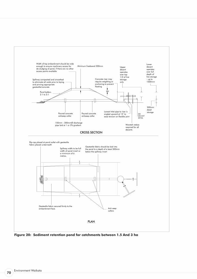
70Environment Waikato
Figure 20: Sediment retention pond for catchments between 1.5 And 3 ha
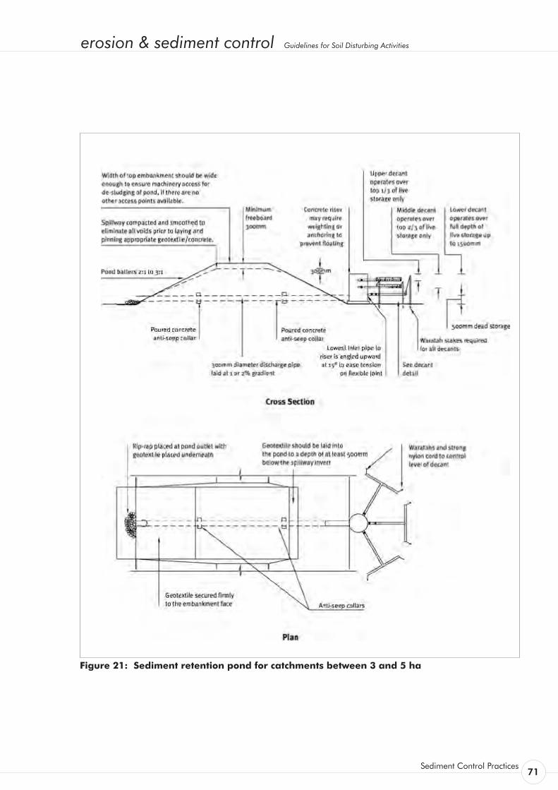
erosion & sediment control Guidelines for Soil Disturbing Activities
Sediment Control Practices 71
Figure 21: Sediment retention pond for catchments between 3 and 5 ha
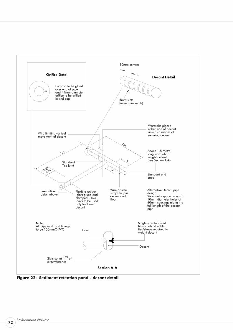
72Environment Waikato
Figure 22: Sediment retention pond - decant detail
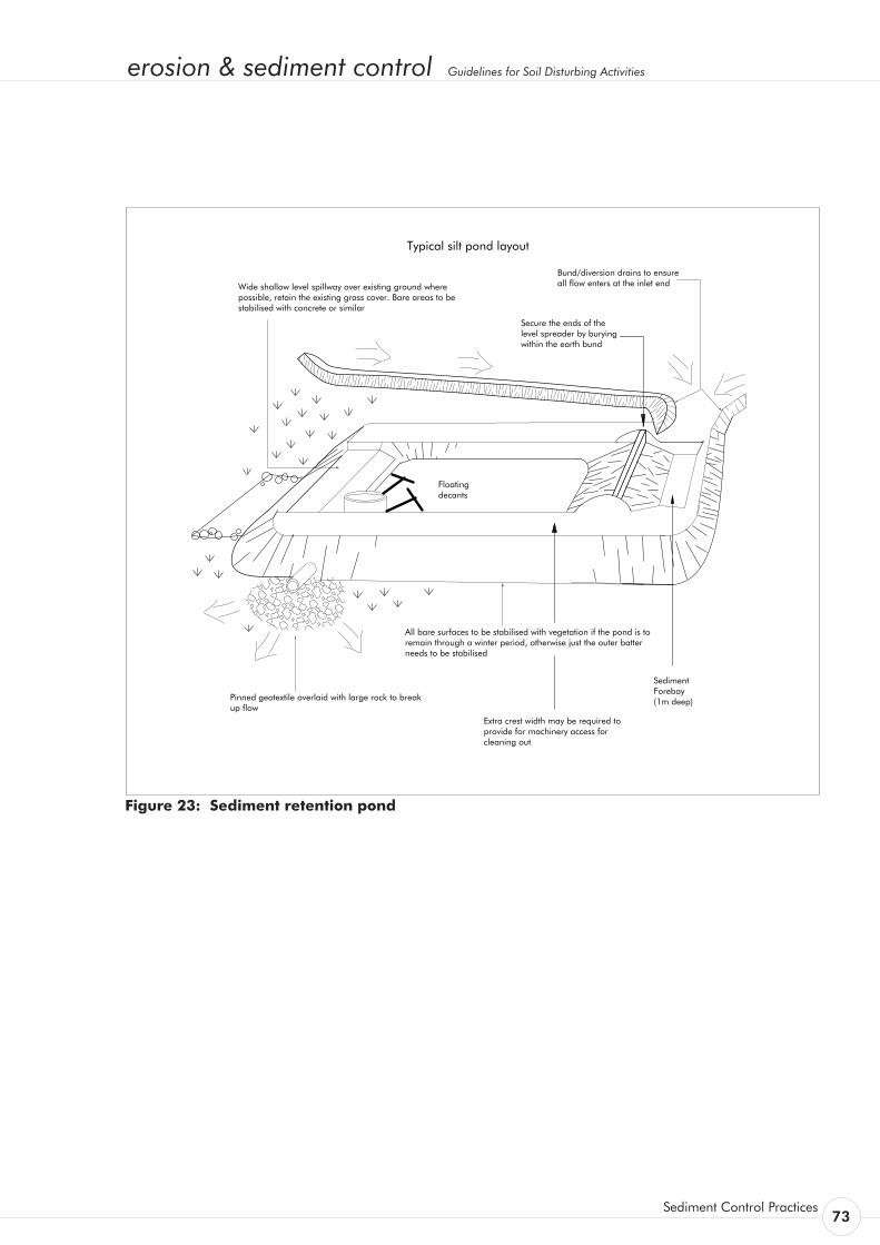
erosion & sediment control Guidelines for Soil Disturbing Activities
Sediment Control Practices 73
Typical silt pond layout
All bare surfaces to be stabilised with vegetation if the pond is to remain through a winter period, otherwise just the outer batter needs to be stabilised
Pinned geotextile overlaid with large rock to break up flow
Wide shallow level spillway over existing ground where possible, retain the existing grass cover. Bare areas to be stabilised with concrete or similar
Bund/diversion drains to ensure all flow enters at the inlet end
Extra crest width may be required to provide for machinery access for cleaning out
SedimentForebay (1m deep)
Secure the ends of the level spreader by burying within the earth bund
Floating decants
Figure 23: Sediment retention pond

74Environment Waikato
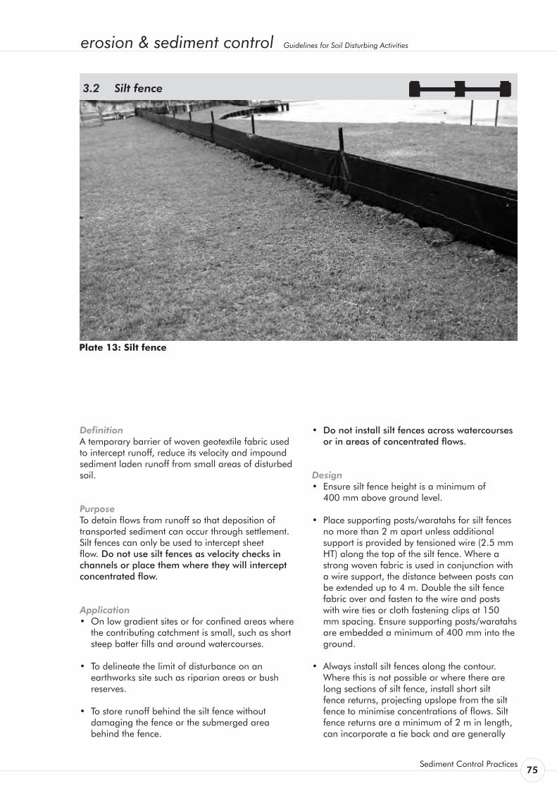
erosion & sediment control Guidelines for Soil Disturbing Activities
Sediment Control Practices 75
Definition A temporary barrier of woven geotextile fabric used to intercept runoff, reduce its velocity and impound sediment laden runoff from small areas of disturbed soil.
Purpose To detain flows from runoff so that deposition of transported sediment can occur through settlement. Silt fences can only be used to intercept sheet flow. Do not use silt fences as velocity checks in channels or place them where they will intercept concentrated flow.
Application • On low gradient sites or for confined areas where
the contributing catchment is small, such as short steep batter fills and around watercourses.
• To delineate the limit of disturbance on an earthworks site such as riparian areas or bush reserves.
• To store runoff behind the silt fence without damaging the fence or the submerged area behind the fence.
Silt fence 3.2
• Do not install silt fences across watercourses or in areas of concentrated flows.
Design • Ensure silt fence height is a minimum of 400 mm above ground level.
• Place supporting posts/waratahs for silt fences no more than 2 m apart unless additional support is provided by tensioned wire (2.5 mm HT) along the top of the silt fence. Where a strong woven fabric is used in conjunction with a wire support, the distance between posts can be extended up to 4 m. Double the silt fence fabric over and fasten to the wire and posts with wire ties or cloth fastening clips at 150 mm spacing. Ensure supporting posts/waratahs are embedded a minimum of 400 mm into the ground.
• Always install silt fences along the contour. Where this is not possible or where there are long sections of silt fence, install short silt fence returns, projecting upslope from the silt fence to minimise concentrations of flows. Silt fence returns are a minimum of 2 m in length, can incorporate a tie back and are generally
Plate 13: Silt fence

76Environment Waikato
constructed by continuing the silt fence around the return and doubling back, to eliminate joins.
• Join lengths of silt fence by doubling over fabric ends around a wooden post or batten or by stapling the fabric ends to a batten and butting the two battens together as shown in Figure 24.
• Maximum slope lengths, spacing of returns and angles for silt fences are shown in Table 11.
• Install silt fence wings at either end of the silt fence projecting upslope to a sufficient height to prevent outflanking.
• Where impounded flow may overtop the silt fence, crossing natural depressions or low points, make provision for a riprap splash pad or other outlet protection device.
• Do not use silt fences in catchments of more than 0.25 ha
• Where water may pond behind the silt fence, provide extra support for the silt fence with tie backs from the silt fence to a central stable point on the upward side. Extra support can also be provided by stringing wire between support stakes and connecting the filter fabric to this wire.
Construction Specifications • Use silt fence material appropriate to the
site conditions and in accordance with the manufacturer’s specifications.
• Excavate a trench a minimum of 100 mm wide and 200 mm deep along the proposed line of the silt fence. Install the support posts on the
downslope edge of the trench and silt fence fabric on the upslope side of the support posts to the full depth of the trench, then backfill the trench with compacted soil.
• Use supporting posts of tanalised timber a minimum of 50 mm square, or steel waratahs at least 1.5 m in length.
• Reinforce the top of the silt fence fabric with a wire support made of galvanised wire of a minimum diameter of 2.5 mm. Tension the wire using permanent wire strainers attached to angled waratahs at the end of the silt fence.
• Where ends of silt fence fabric come together, ensure they are overlapped, folded and stapled to prevent sediment bypass.
Maintenance • Inspect silt fences at least once a week and
after each rainfall. Make any necessary repairs when bulges occur or when sediment accumulation reaches 50 percent of the fabric height.
• Any areas of collapse, decomposition or ineffectiveness need to be immediately replaced.
• Remove sediment deposits as necessary to continue to allow for adequate sediment storage and reduce pressure on the silt fence. Ensure that the sediment is removed to a secure area.
• Do not remove silt fence materials and sediment deposition until the catchment area has been appropriately stabilised. Stabilise the area of the removed silt fence.
Table 11: Silt fence design criteria
Slope Steepness (%)
Slope Length (m) (Maximum)
Spacing of Returns (m) Silt fence Length (m) (Maximum)
Flatter than 2% Unlimited N/A Unlimited
2 - 10% 40 60 300
10 - 20% 30 50 230
20 - 33% 20 40 150
33 - 50% 15 30 75
> 50% 6 20 40
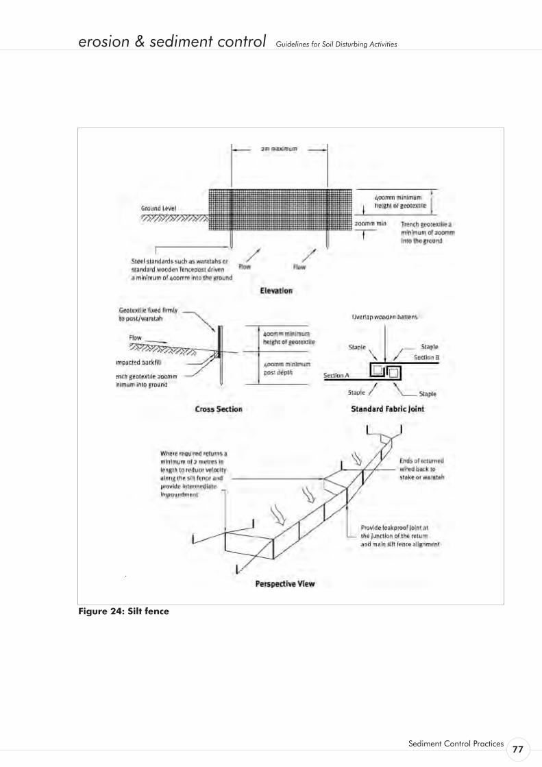
erosion & sediment control Guidelines for Soil Disturbing Activities
Sediment Control Practices 77
Figure 24: Silt fence

78Environment Waikato
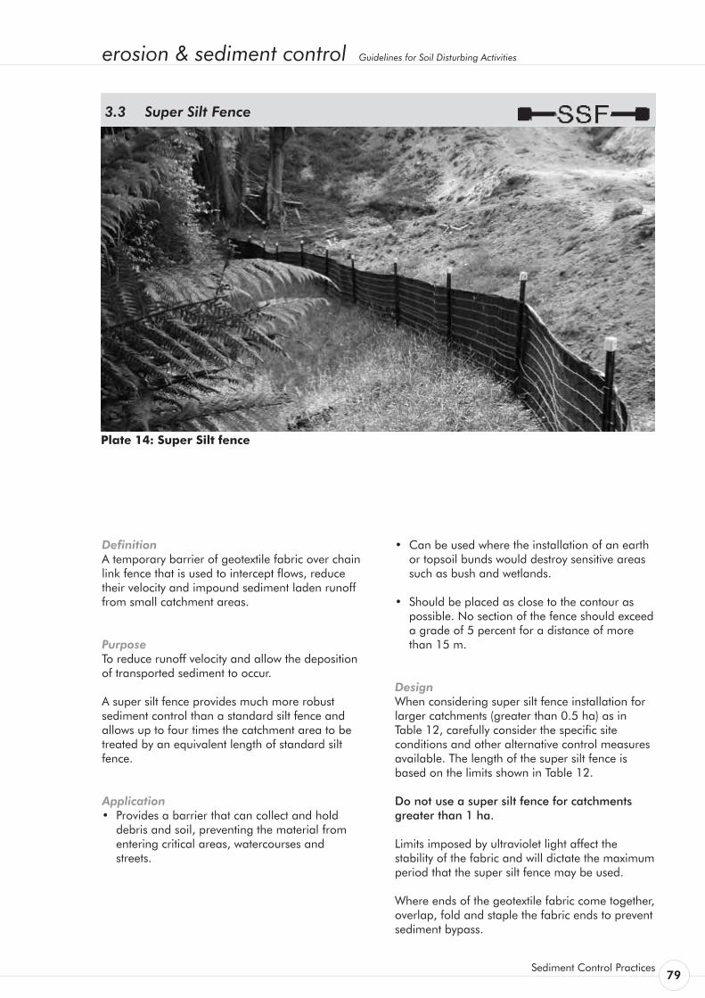
erosion & sediment control Guidelines for Soil Disturbing Activities
Sediment Control Practices 79
Definition A temporary barrier of geotextile fabric over chain link fence that is used to intercept flows, reduce their velocity and impound sediment laden runoff from small catchment areas.
Purpose To reduce runoff velocity and allow the deposition of transported sediment to occur.
A super silt fence provides much more robust sediment control than a standard silt fence and allows up to four times the catchment area to be treated by an equivalent length of standard silt fence.
Application • Provides a barrier that can collect and hold
debris and soil, preventing the material from entering critical areas, watercourses and streets.
Super Silt Fence 3.3
• Can be used where the installation of an earth or topsoil bunds would destroy sensitive areas such as bush and wetlands.
• Should be placed as close to the contour as possible. No section of the fence should exceed a grade of 5 percent for a distance of more than 15 m.
Design When considering super silt fence installation for larger catchments (greater than 0.5 ha) as in Table 12, carefully consider the specific site conditions and other alternative control measures available. The length of the super silt fence is based on the limits shown in Table 12.
Do not use a super silt fence for catchments greater than 1 ha.
Limits imposed by ultraviolet light affect the stability of the fabric and will dictate the maximum period that the super silt fence may be used.
Where ends of the geotextile fabric come together, overlap, fold and staple the fabric ends to prevent sediment bypass.
Plate 14: Super Silt fence

80Environment Waikato
Construction Specifications • Use a silt fence fabric that is appropriate to
the site conditions and fits the manufacturer’s specifications.
• Excavate a trench 100 mm wide by 200 mm deep along the line of the super silt fence.
• Position the posts (No. 3 rounds, No. 2 half rounds or waratahs) at no greater than 3 m centres on the downslope side of the trench. While there is no need to set the posts in concrete, ensure the 1.8 m long posts are driven to an appropriate depth (0.8 m minimum).
• Install tensioned galvanised wire (2.5 mm HT) at 400 mm and again at 700 mm above ground level using permanent wire strainers.
• Secure chain link fence to the fence posts with wire ties or staples, ensuring the chain link fence goes to the base of the trench.
• Fasten two layers of geotextile fabric securely to the super silt fence with ties spaced every 60 cm at the top and mid section of the super silt fence.
• Place the two layers of geotextile fabric to the base of the trench (a minimum of 200 mm into the ground) and place compacted backfill back to the original ground level.
• When two sections of geotextile fabric adjoin each other, ensure they are doubled over a minimum of 300 mm, wrapped around a batten and stapled at 75 mm spacings to prevent sediment bypass.
Maintenance Inspect regularly and before and after storm events.
Undertake maintenance as needed and remove silt buildups when bulges develop in the super silt fence or when sediment deposition reaches 50 percent of the super silt fence height.
Table 12: Super Silt Fence Design Criteria
Slope
Steepness (%)
Slope Length (m)
(Maximum)
Silt fence Length (m)
(Maximum)
0 - 10% Unlimited Unlimited
10 - 20% 60 450
20 - 33% 30 300
33 - 50% 30 150
> 50% 15 75
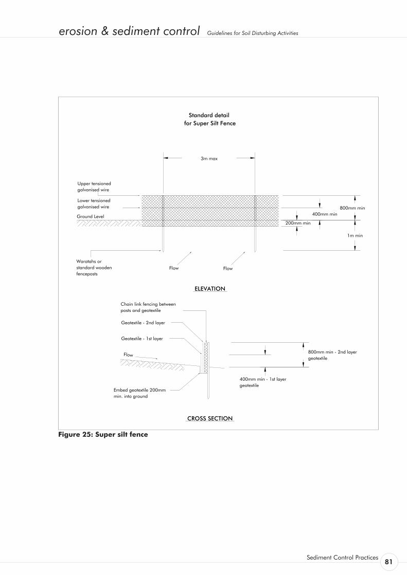
erosion & sediment control Guidelines for Soil Disturbing Activities
Sediment Control Practices 81
for Super Silt FenceStandard detail
ELEVATION
800mm min
1m min
3m max
200mm min
400mm min
Waratahs or standard wooden fenceposts
Ground Level
Flow 800mm min - 2nd layer geotextile
400mm min - 1st layer geotextile
Embed geotextile 200mm min. into ground
Chain link fencing between posts and geotextile
Geotextile - 2nd layer
Geotextile - 1st layer
CROSS SECTION
Flow Flow
TP90_16.dwg
Upper tensioned galvanised wire
Lower tensioned galvanised wire
Figure 25: Super silt fence

82Environment Waikato
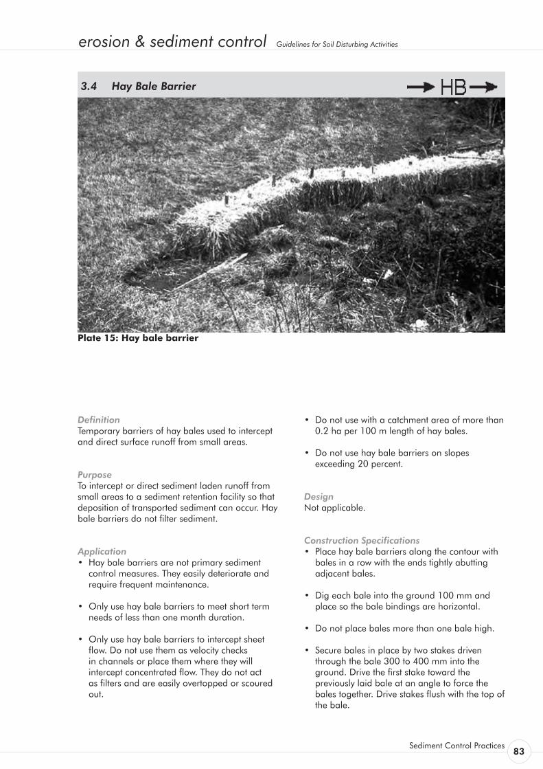
erosion & sediment control Guidelines for Soil Disturbing Activities
Sediment Control Practices 83
Definition Temporary barriers of hay bales used to intercept and direct surface runoff from small areas.
Purpose To intercept or direct sediment laden runoff from small areas to a sediment retention facility so that deposition of transported sediment can occur. Hay bale barriers do not filter sediment.
Application • Hay bale barriers are not primary sediment
control measures. They easily deteriorate and require frequent maintenance.
• Only use hay bale barriers to meet short term needs of less than one month duration.
• Only use hay bale barriers to intercept sheet flow. Do not use them as velocity checks in channels or place them where they will intercept concentrated flow. They do not act as filters and are easily overtopped or scoured out.
Hay Bale Barrier 3.4
• Do not use with a catchment area of more than 0.2 ha per 100 m length of hay bales.
• Do not use hay bale barriers on slopes exceeding 20 percent.
Design Not applicable.
Construction Specifications • Place hay bale barriers along the contour with
bales in a row with the ends tightly abutting adjacent bales.
• Dig each bale into the ground 100 mm and place so the bale bindings are horizontal.
• Do not place bales more than one bale high.
• Secure bales in place by two stakes driven through the bale 300 to 400 mm into the ground. Drive the first stake toward the previously laid bale at an angle to force the bales together. Drive stakes flush with the top of the bale.
Plate 15: Hay bale barrier
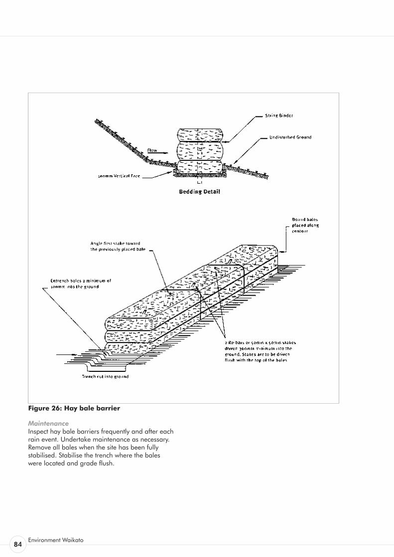
84Environment Waikato
Figure 26: Hay bale barrier
Maintenance Inspect hay bale barriers frequently and after each rain event. Undertake maintenance as necessary. Remove all bales when the site has been fully stabilised. Stabilise the trench where the bales were located and grade flush.
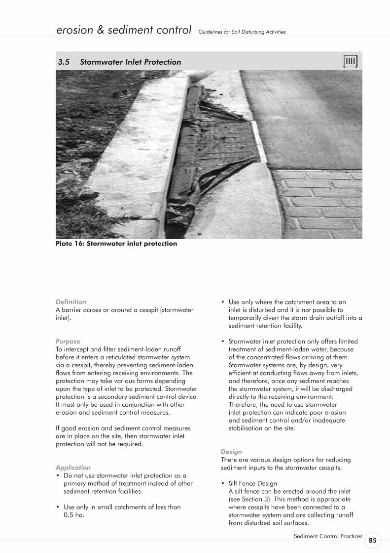
erosion & sediment control Guidelines for Soil Disturbing Activities
Sediment Control Practices 85
Plate 16: Stormwater inlet protection
Definition A barrier across or around a cesspit (stormwater inlet).
Purpose To intercept and filter sediment-laden runoff before it enters a reticulated stormwater system via a cesspit, thereby preventing sediment-laden flows from entering receiving environments. The protection may take various forms depending upon the type of inlet to be protected. Stormwater protection is a secondary sediment control device. It must only be used in conjunction with other erosion and sediment control measures.
If good erosion and sediment control measures are in place on the site, then stormwater inlet protection will not be required.
Application • Do not use stormwater inlet protection as a
primary method of treatment instead of other sediment retention facilities.
• Use only in small catchments of less than 0.5 ha.
Stormwater Inlet Protection 3.5
• Use only where the catchment area to an inlet is disturbed and it is not possible to temporarily divert the storm drain outfall into a sediment retention facility.
• Stormwater inlet protection only offers limited treatment of sediment-laden water, because of the concentrated flows arriving at them. Stormwater systems are, by design, very efficient at conducting flows away from inlets, and therefore, once any sediment reaches the stormwater system, it will be discharged directly to the receiving environment. Therefore, the need to use stormwater inlet protection can indicate poor erosion and sediment control and/or inadequate stabilisation on the site.
Design There are various design options for reducing sediment inputs to the stormwater cesspits.
• Silt Fence Design A silt fence can be erected around the inlet
(see Section 3). This method is appropriate where cesspits have been connected to a stormwater system and are collecting runoff from disturbed soil surfaces.
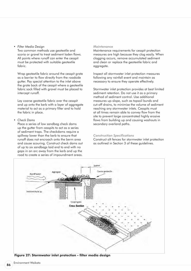
86Environment Waikato
• FilterMediaDesign Two common methods use geotextile and
scoria or gravel to treat sediment laden flows. All points where runoff can enter the cesspit must be protected with suitable geotextile fabric.
Wrap geotextile fabric around the cesspit grate as a barrier to flow directly from the roadside gutter. Pay special attention to the inlet above the grate back of the cesspit where a geotextile fabric sock filled with gravel must be placed to intercept runoff.
Lay coarse geotextile fabric over the cesspit and up onto the kerb with a layer of aggregate material to act as a primary filter and to hold the fabric in place.
• CheckDams Place a series of low sandbag check dams
up the gutter from cesspits to act as a series of sediment traps. The checkdams require a spillway lower than the kerb to ensure that runoff does not encroach onto the berm area and cause scouring. Construct check dams out of up to six sandbags laid end to end with no gaps in an arc away from the kerb and up the road to create a series of impoundment areas.
Maintenance Maintenance requirements for cesspit protection measures are high because they clog easily. When clogging occurs, remove accumulated sediment and clean or replace the geotextile fabric and aggregate.
Inspect all stormwater inlet protection measures following any rainfall event and maintain as necessary to ensure they operate effectively.
Stormwater inlet protection provides at best limited sediment retention. Do not use it as a primary method of sediment control. Use additional measures up-slope, such as topsoil bunds and cut-off drains, to minimise the volume of sediment reaching any stormwater inlets. Cesspits must at all times remain able to convey flow from the site to prevent large concentrated highly erosive flows from building up and causing washouts in secondary overland paths.
Construction Specifications Construct silt fences for stormwater inlet protection as outlined in Section 3 of these guidelines.
Figure 27: Stormwater inlet protection - filter media design
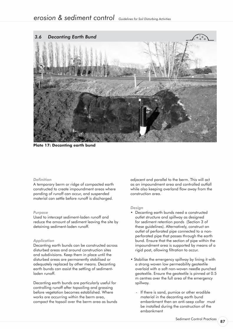
erosion & sediment control Guidelines for Soil Disturbing Activities
Sediment Control Practices 87
Plate 17: Decanting earth bund
Definition A temporary berm or ridge of compacted earth constructed to create impoundment areas where ponding of runoff can occur, and suspended material can settle before runoff is discharged.
Purpose Used to intercept sediment-laden runoff and reduce the amount of sediment leaving the site by detaining sediment-laden runoff.
Application Decanting earth bunds can be constructed across disturbed areas and around construction sites and subdivisions. Keep them in place until the disturbed areas are permanently stabilised or adequately replaced by other means. Decanting earth bunds can assist the settling of sediment-laden runoff.
Decanting earth bunds are particularly useful for controlling runoff after topsoiling and grassing before vegetation becomes established. Where works are occurring within the berm area, compact the topsoil over the berm area as bunds
Decanting Earth Bund 3.6
adjacent and parallel to the berm. This will act as an impoundment area and controlled outfall while also keeping overland flow away from the construction area.
Design • Decanting earth bunds need a constructed
outlet structure and spillway as designed for sediment retention ponds (Section 3 of these guidelines). Alternatively, construct an outlet of perforated pipe connected to a non-perforated pipe that passes through the earth bund. Ensure that the section of pipe within the impoundment area is supported by means of a rigid post, allowing filtration to occur.
• Stabilise the emergency spillway by lining it with a strong woven low permeability geotextile overlaid with a soft non-woven needle punched
geotextile. Ensure the geotextile is pinned at 0.5 m centres over the full area of the emergency spillway.
- If there is sand, pumice or other erodible material in the decanting earth bund embankment then an anti-seep collar must be installed during the construction of the embankment
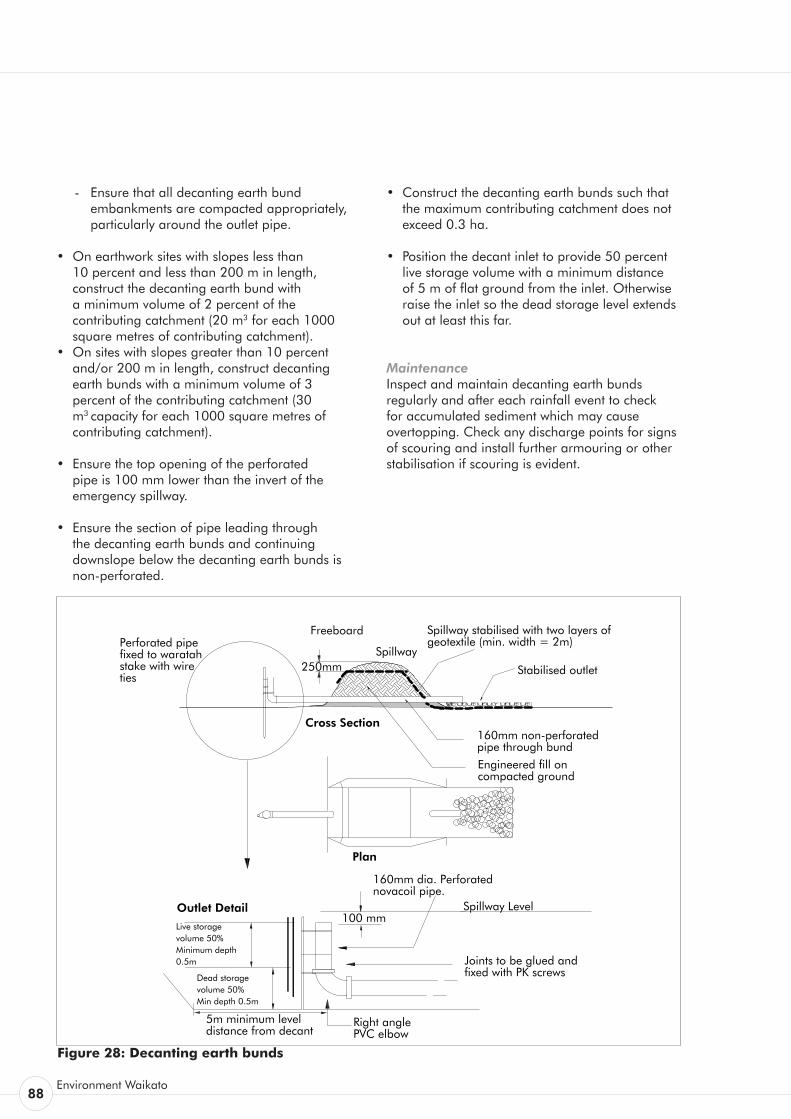
88Environment Waikato
- Ensure that all decanting earth bund embankments are compacted appropriately, particularly around the outlet pipe.
• On earthwork sites with slopes less than 10 percent and less than 200 m in length, construct the decanting earth bund with a minimum volume of 2 percent of the contributing catchment (20 m3 for each 1000 square metres of contributing catchment).
• On sites with slopes greater than 10 percent and/or 200 m in length, construct decanting earth bunds with a minimum volume of 3 percent of the contributing catchment (30 m3 capacity for each 1000 square metres of contributing catchment).
• Ensure the top opening of the perforated pipe is 100 mm lower than the invert of the emergency spillway.
• Ensure the section of pipe leading through the decanting earth bunds and continuing downslope below the decanting earth bunds is non-perforated.
• Construct the decanting earth bunds such that the maximum contributing catchment does not exceed 0.3 ha.
• Position the decant inlet to provide 50 percent live storage volume with a minimum distance of 5 m of flat ground from the inlet. Otherwise raise the inlet so the dead storage level extends out at least this far.
Maintenance Inspect and maintain decanting earth bunds regularly and after each rainfall event to check for accumulated sediment which may cause overtopping. Check any discharge points for signs of scouring and install further armouring or other stabilisation if scouring is evident.
Figure 28: Decanting earth bunds
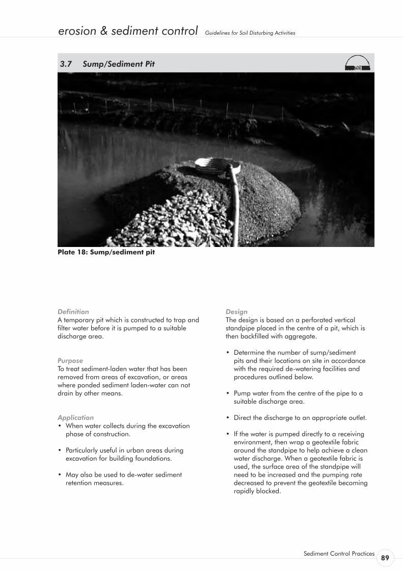
erosion & sediment control Guidelines for Soil Disturbing Activities
Sediment Control Practices 89
Definition A temporary pit which is constructed to trap and filter water before it is pumped to a suitable discharge area.
Purpose To treat sediment-laden water that has been removed from areas of excavation, or areas where ponded sediment laden-water can not drain by other means.
Application • When water collects during the excavation
phase of construction.
• Particularly useful in urban areas during excavation for building foundations.
• May also be used to de-water sediment retention measures.
Sump/Sediment Pit 3.7
Design The design is based on a perforated vertical standpipe placed in the centre of a pit, which is then backfilled with aggregate.
• Determine the number of sump/sediment pits and their locations on site in accordance with the required de-watering facilities and procedures outlined below.
• Pump water from the centre of the pipe to a suitable discharge area.
• Direct the discharge to an appropriate outlet.
• If the water is pumped directly to a receiving environment, then wrap a geotextile fabric around the standpipe to help achieve a clean water discharge. When a geotextile fabric is used, the surface area of the standpipe will need to be increased and the pumping rate decreased to prevent the geotextile becoming rapidly blocked.
Plate 18: Sump/sediment pit
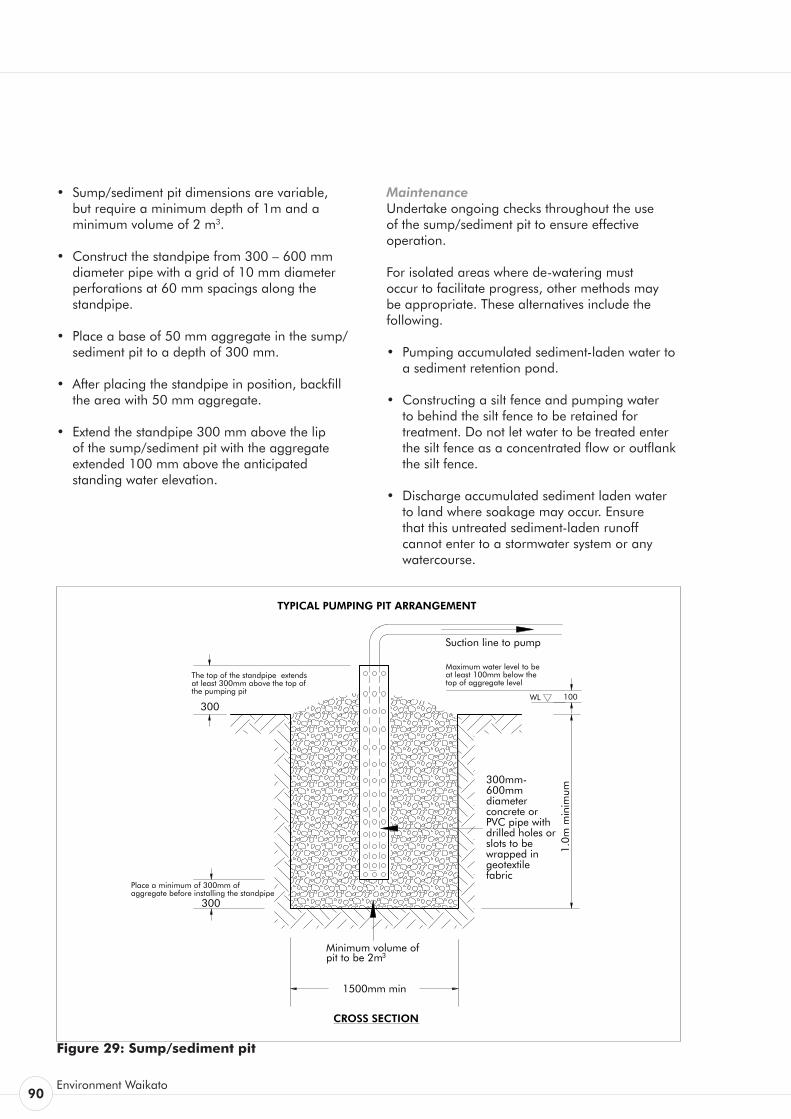
90Environment Waikato
• Sump/sediment pit dimensions are variable, but require a minimum depth of 1m and a minimum volume of 2 m3.
• Construct the standpipe from 300 – 600 mm diameter pipe with a grid of 10 mm diameter perforations at 60 mm spacings along the standpipe.
• Place a base of 50 mm aggregate in the sump/sediment pit to a depth of 300 mm.
• After placing the standpipe in position, backfill the area with 50 mm aggregate.
• Extend the standpipe 300 mm above the lip of the sump/sediment pit with the aggregate extended 100 mm above the anticipated standing water elevation.
Maintenance Undertake ongoing checks throughout the use of the sump/sediment pit to ensure effective operation.
For isolated areas where de-watering must occur to facilitate progress, other methods may be appropriate. These alternatives include the following.
• Pumping accumulated sediment-laden water to a sediment retention pond.
• Constructing a silt fence and pumping water to behind the silt fence to be retained for treatment. Do not let water to be treated enter the silt fence as a concentrated flow or outflank the silt fence.
• Discharge accumulated sediment laden water to land where soakage may occur. Ensure that this untreated sediment-laden runoff cannot enter to a stormwater system or any watercourse.
Figure 29: Sump/sediment pit
300mm-600mm diameter concrete or PVC pipe with drilled holes or slots to be wrapped in geotextile fabric
Suction line to pump
Maximum water level to be at least 100mm below the top of aggregate level
CROSS SECTION
100
The top of the standpipe extends at least 300mm above the top of the pumping pit
Place a minimum of 300mm of aggregate before installing the standpipe
1500mm min
1.0m
min
imum
300
300WL
TYPICAL PUMPING PIT ARRANGEMENT
Minimum volume of pit to be 2m3
erosion & sediment control Guidelines for Soil Disturbing Activities
Works within a Watercourse 91
Works Within A Watercourse 4.
Works within watercourses have very high potential for erosion and discharge of sediment. This is because such work is undertaken in or near flowing water - the major cause of erosion. Flowing water causes ongoing scour and provides the transport mechanism to allow sediment to be dispersed downstream of the works and ultimately, into marine or lake environments.
Such works may also require a range of control measures additional to those detailed below. These other measures are described in other sections of these guidelines and include both erosion control and sediment control techniques.
Design and planning consideration for a permanent watercourse crossing need to take into account the permanent nature of the crossing in question. Be sure that they are constructed in accordance with all relevant requirements.

92Environment Waikato
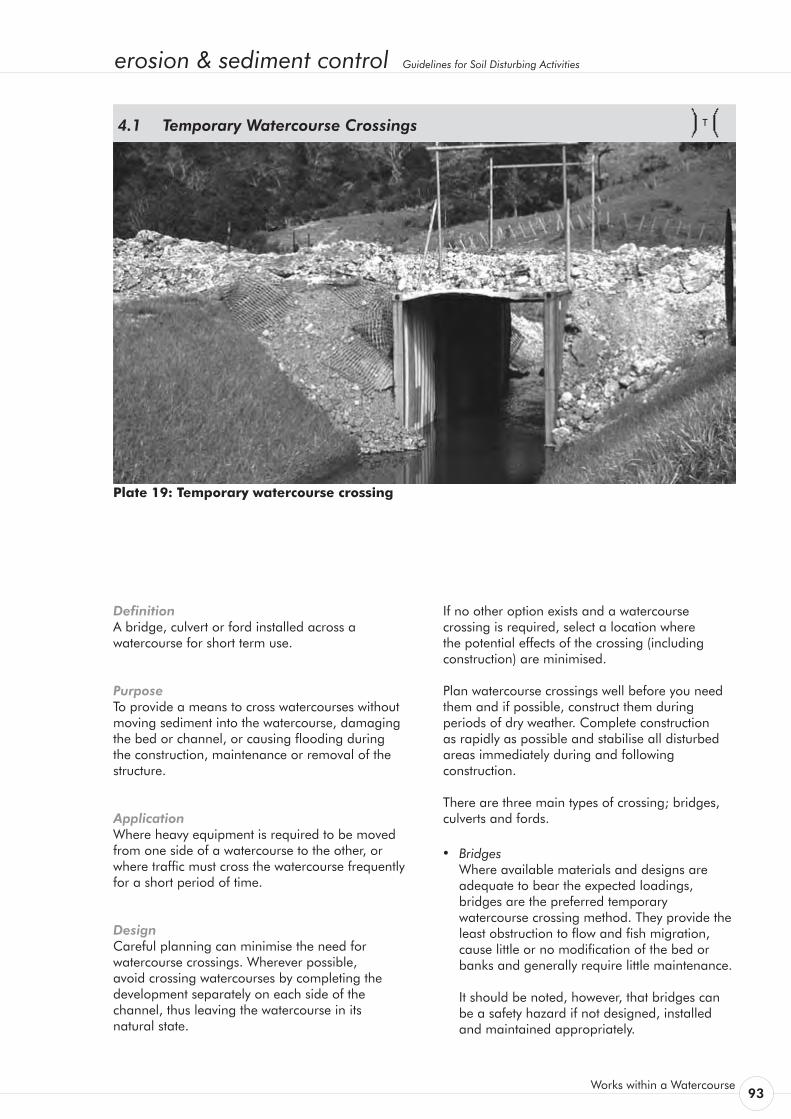
erosion & sediment control Guidelines for Soil Disturbing Activities
Works within a Watercourse 93
Definition A bridge, culvert or ford installed across a watercourse for short term use.
Purpose To provide a means to cross watercourses without moving sediment into the watercourse, damaging the bed or channel, or causing flooding during the construction, maintenance or removal of the structure.
Application Where heavy equipment is required to be moved from one side of a watercourse to the other, or where traffic must cross the watercourse frequently for a short period of time.
Design Careful planning can minimise the need for watercourse crossings. Wherever possible, avoid crossing watercourses by completing the development separately on each side of the channel, thus leaving the watercourse in its natural state.
Temporary Watercourse Crossings 4.1
If no other option exists and a watercourse crossing is required, select a location where the potential effects of the crossing (including construction) are minimised.
Plan watercourse crossings well before you need them and if possible, construct them during periods of dry weather. Complete construction as rapidly as possible and stabilise all disturbed areas immediately during and following construction.
There are three main types of crossing; bridges, culverts and fords.
• Bridges Where available materials and designs are
adequate to bear the expected loadings, bridges are the preferred temporary watercourse crossing method. They provide the least obstruction to flow and fish migration, cause little or no modification of the bed or banks and generally require little maintenance.
It should be noted, however, that bridges can be a safety hazard if not designed, installed and maintained appropriately.
Plate 19: Temporary watercourse crossing

94Environment Waikato
• Culvert Crossings Culverts are the most commonly used type of
temporary watercourse crossing, and can be easily adapted to most site conditions. The installation and removal of culverts, however, causes considerable damage to watercourses and can also create the greatest obstruction to flood flows.
• Fords Made of stabilising material such as rock, fords
are often used in steep catchments subject to flooding, but where normal flows are shallow. Only use fords where crossing requirements are infrequent. They can offer little or no obstruction to flows, are relatively easy to install and maintain.
As well as erosion and sediment control measures, structural stability, utility and safety must also be taken into account when designing temporary watercourse crossings.
Any temporary crossing must comply with the technical requirements of the various agencies involved and any specific requirements imposed by Environment Waikato.
When the structure is no longer needed, remove the structure and all material from the site. Immediately stabilise all areas disturbed during the removal process by re-vegetation or artificial protection as a short term control measure. Keep machinery clear of the watercourse while removing the structure.
Maintenance Inspect temporary watercourse crossings after rain to check for blockage in the channel, erosion of the banks, channel scour or signs of instability. Make all repairs immediately to prevent further damage to the installation.
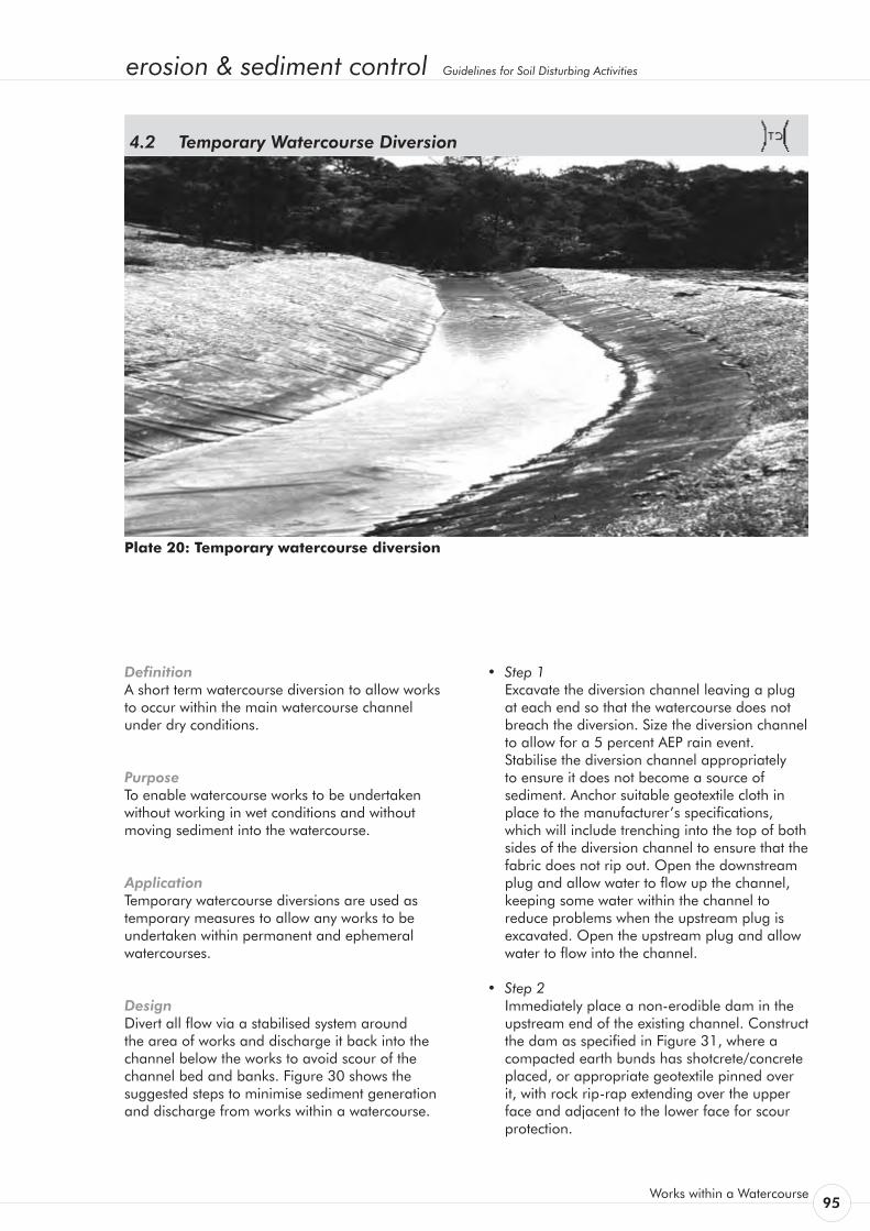
erosion & sediment control Guidelines for Soil Disturbing Activities
Works within a Watercourse 95
Definition A short term watercourse diversion to allow works to occur within the main watercourse channel under dry conditions.
Purpose To enable watercourse works to be undertaken without working in wet conditions and without moving sediment into the watercourse.
Application Temporary watercourse diversions are used as temporary measures to allow any works to be undertaken within permanent and ephemeral watercourses.
Design Divert all flow via a stabilised system around the area of works and discharge it back into the channel below the works to avoid scour of the channel bed and banks. Figure 30 shows the suggested steps to minimise sediment generation and discharge from works within a watercourse.
Temporary Watercourse Diversion 4.2
Plate 20: Temporary watercourse diversion
• Step1 Excavate the diversion channel leaving a plug
at each end so that the watercourse does not breach the diversion. Size the diversion channel to allow for a 5 percent AEP rain event. Stabilise the diversion channel appropriately to ensure it does not become a source of sediment. Anchor suitable geotextile cloth in place to the manufacturer’s specifications, which will include trenching into the top of both sides of the diversion channel to ensure that the fabric does not rip out. Open the downstream plug and allow water to flow up the channel, keeping some water within the channel to reduce problems when the upstream plug is excavated. Open the upstream plug and allow water to flow into the channel.
• Step2 Immediately place a non-erodible dam in the
upstream end of the existing channel. Construct the dam as specified in Figure 31, where a compacted earth bunds has shotcrete/concrete placed, or appropriate geotextile pinned over it, with rock rip-rap extending over the upper face and adjacent to the lower face for scour protection.
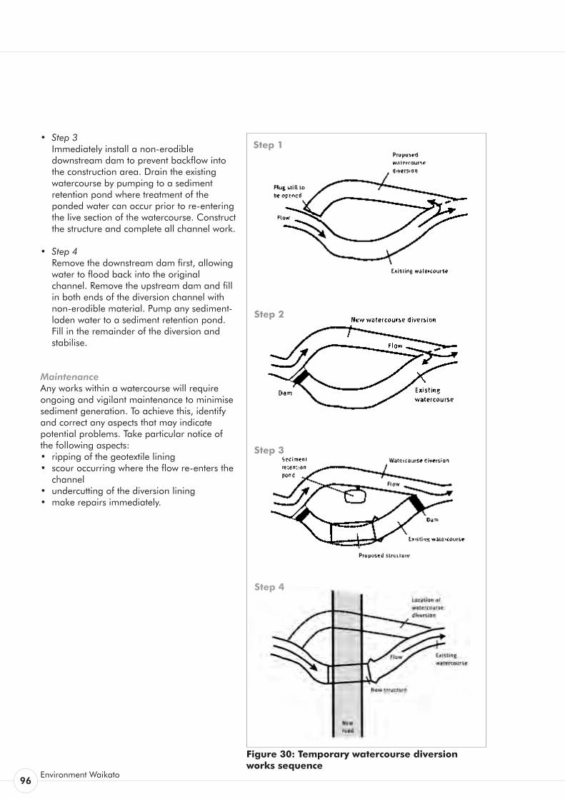
96Environment Waikato
• Step3 Immediately install a non-erodible
downstream dam to prevent backflow into the construction area. Drain the existing watercourse by pumping to a sediment retention pond where treatment of the ponded water can occur prior to re-entering the live section of the watercourse. Construct the structure and complete all channel work.
• Step4 Remove the downstream dam first, allowing
water to flood back into the original channel. Remove the upstream dam and fill in both ends of the diversion channel with non-erodible material. Pump any sediment-laden water to a sediment retention pond. Fill in the remainder of the diversion and stabilise.
Maintenance Any works within a watercourse will require ongoing and vigilant maintenance to minimise sediment generation. To achieve this, identify and correct any aspects that may indicate potential problems. Take particular notice of the following aspects: • ripping of the geotextile lining • scour occurring where the flow re-enters the
channel • undercutting of the diversion lining• make repairs immediately.
Figure 30: Temporary watercourse diversion works sequence
Step 1
Step 2
Step 3
Step 4
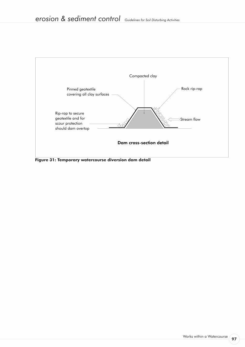
erosion & sediment control Guidelines for Soil Disturbing Activities
Works within a Watercourse 97
Pinned geotextile covering all clay surfaces
Compacted clay
Rock rip-rap
Stream flowRip-rap to secure geotextile and for scour protection should dam overtop
Dam cross-section detail
Figure 31: Temporary watercourse diversion dam detail

98Environment Waikato
erosion & sediment control Guidelines for Soil Disturbing Activities
Works within a Watercourse 99
Definition A bridge, culvert or ford installed across a watercourse for ongoing use.
Purpose To provide a means to cross watercourses by a vehicle without moving sediment into the watercourse, damaging the bed or channel, or causing flooding during the construction, operation or maintenance of the structure.
Application Where permanent access is required across a small watercourse.
If no other option exists and a watercourse crossing is required, select a location where the potential effects of the crossing (including construction) are minimised. Plan water crossings well before you need to use them and if possible, construct them during periods of dry weather. Complete construction as rapidly as possible and stabilise all disturbed areas immediately during and following construction.
There are three main types of watercourse crossing; bridges, culverts and fords.
Permanent Watercourse Crossings 4.3

100Environment Waikato
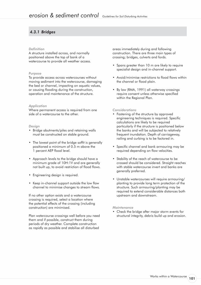
erosion & sediment control Guidelines for Soil Disturbing Activities
Works within a Watercourse 101
Definition A structure installed across, and normally positioned above the top of bank of a watercourse to provide all weather access.
Purpose To provide access across watercourses without moving sediment into the watercourse, damaging the bed or channel, impacting on aquatic values, or causing flooding during the construction, operation and maintenance of the structure.
Application Where permanent access is required from one side of a watercourse to the other.
Design • Bridge abutments/piles and retaining walls
must be constructed on stable ground.
• The lowest point of the bridge soffit is generally positioned a minimum of 0.5 m above the
1 percent AEP flood level.
• Approach levels to the bridge should have a minimum grade of 10H:1V and are generally not built up, to avoid restriction of flood flows.
• Engineering design is required.
• Keep in-channel support outside the low flow channel to minimise changes to stream flows.
If no other option exists and a watercourse crossing is required, select a location where the potential effects of the crossing (including construction) are minimised.
Plan watercourse crossings well before you need them and if possible, construct them during periods of dry weather. Complete construction as rapidly as possible and stabilise all disturbed
Bridges 4.3.1
areas immediately during and following construction. There are three main types of crossing; bridges, culverts and fords.
• Spans greater than 10 m are likely to require specialist design and in-channel support.
• Avoid/minimise restrictions to flood flows within the channel or flood plain.
• By law (RMA, 1991) all waterway crossings require consent unless otherwise specified within the Regional Plan.
Considerations • Fastening of the structure by approved
engineering techniques is required. Specific calculations are likely to be required particularly if the structure is positioned below the banks and will be subjected to relatively frequent inundation. Depth of carriageway, railing and curbing is to be factored in.
• Specific channel and bank armouring may be required depending on flow velocities.
• Stability of the reach of watercourse to be crossed should be considered. Straight reaches with stable watercourse invert and banks are generally preferred.
• Unstable watercourses will require armouring/ planting to provide long term protection of the structure. Such armouring/planting may be required to extend considerable distances both upstream and downstream.
Maintenance • Check the bridge after major storm events for
structural integrity, debris build up and erosion.
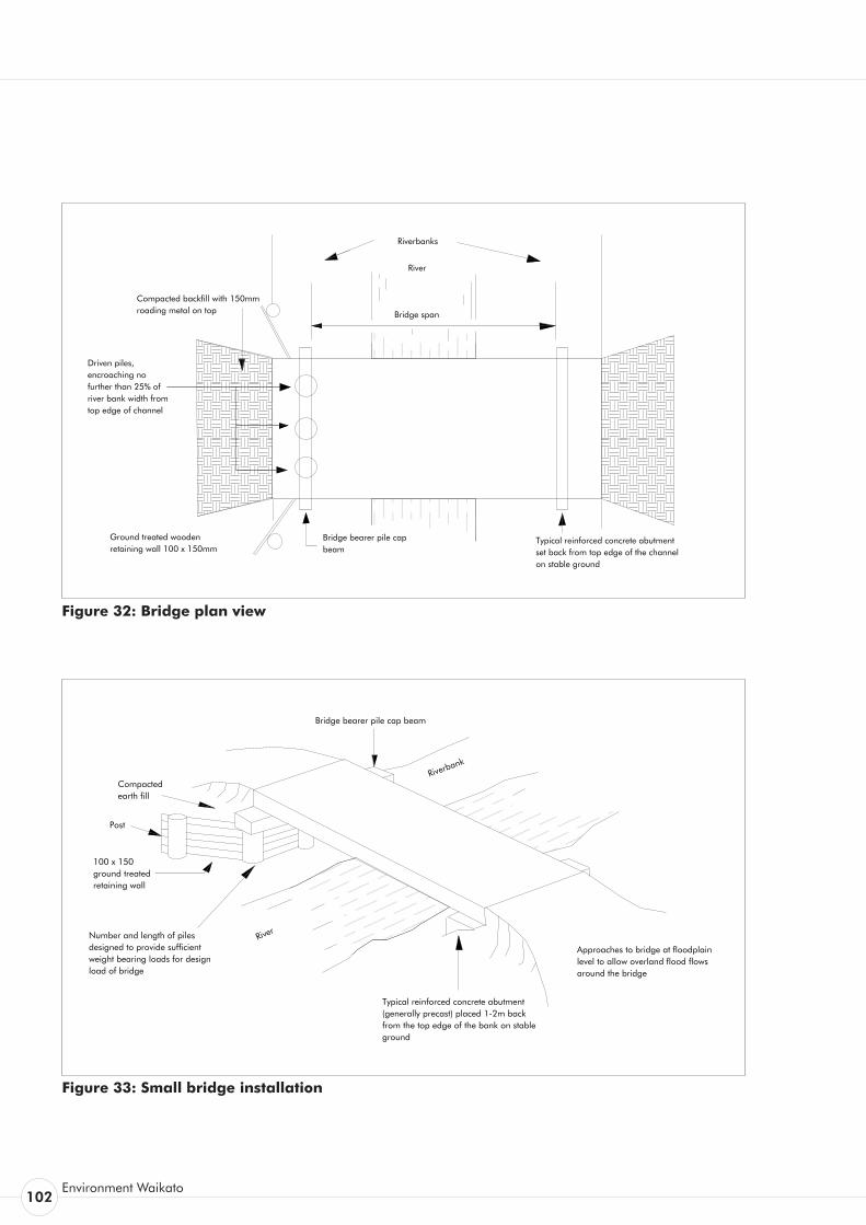
102Environment Waikato
Bridge span
Typical reinforced concrete abutment set back from top edge of the channel on stable ground
Bridge bearer pile cap beam
Compacted backfill with 150mm roading metal on top
River
Riverbanks
Driven piles, encroaching no further than 25% of river bank width from top edge of channel
Ground treated wooden retaining wall 100 x 150mm
Figure 32: Bridge plan view
Figure 33: Small bridge installation
Approaches to bridge at floodplain level to allow overland flood flows around the bridge
Typical reinforced concrete abutment (generally precast) placed 1-2m back from the top edge of the bank on stable ground
River
Compacted earth fill
Bridge bearer pile cap beam
100 x 150 ground treated retaining wall
Number and length of piles designed to provide sufficient weight bearing loads for design load of bridge
Post
Riverbank
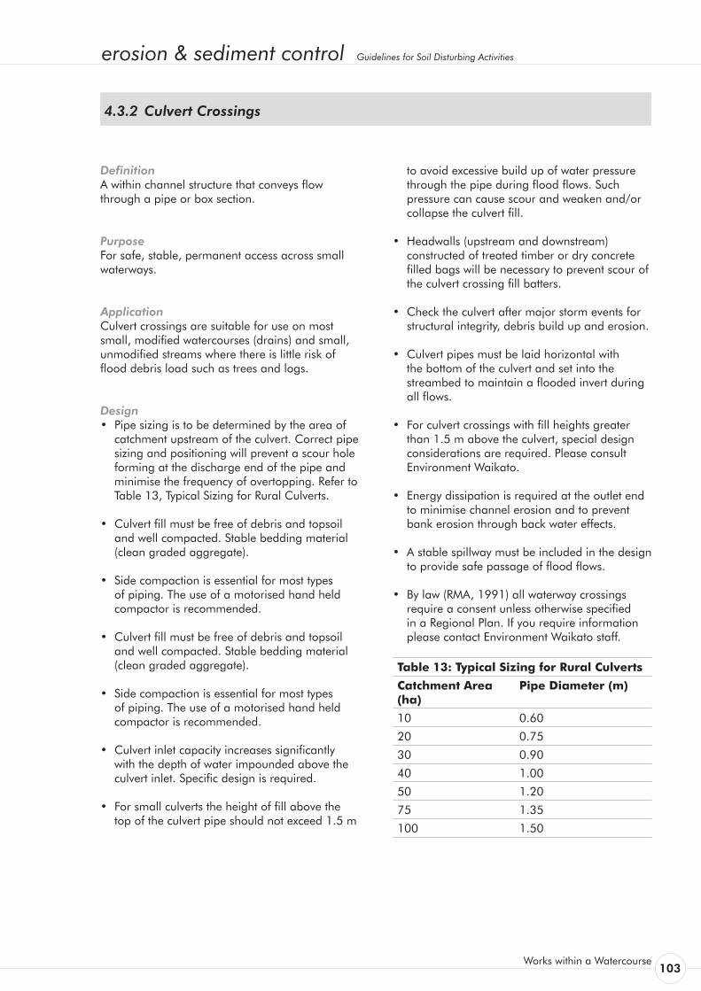
erosion & sediment control Guidelines for Soil Disturbing Activities
Works within a Watercourse 103
Definition A within channel structure that conveys flow through a pipe or box section.
Purpose For safe, stable, permanent access across small waterways.
Application Culvert crossings are suitable for use on most small, modified watercourses (drains) and small, unmodified streams where there is little risk of flood debris load such as trees and logs.
Design • Pipe sizing is to be determined by the area of
catchment upstream of the culvert. Correct pipe sizing and positioning will prevent a scour hole forming at the discharge end of the pipe and minimise the frequency of overtopping. Refer to
Table 13, Typical Sizing for Rural Culverts.
• Culvert fill must be free of debris and topsoil and well compacted. Stable bedding material (clean graded aggregate).
• Side compaction is essential for most types of piping. The use of a motorised hand held compactor is recommended.
• Culvert fill must be free of debris and topsoil and well compacted. Stable bedding material (clean graded aggregate).
• Side compaction is essential for most types of piping. The use of a motorised hand held compactor is recommended.
• Culvert inlet capacity increases significantly with the depth of water impounded above the culvert inlet. Specific design is required.
• For small culverts the height of fill above the top of the culvert pipe should not exceed 1.5 m
Culvert Crossings 4.3.2
to avoid excessive build up of water pressure through the pipe during flood flows. Such pressure can cause scour and weaken and/or collapse the culvert fill.
• Headwalls (upstream and downstream) constructed of treated timber or dry concrete filled bags will be necessary to prevent scour of the culvert crossing fill batters.
• Check the culvert after major storm events for structural integrity, debris build up and erosion.
• Culvert pipes must be laid horizontal with the bottom of the culvert and set into the streambed to maintain a flooded invert during all flows.
• For culvert crossings with fill heights greater than 1.5 m above the culvert, special design considerations are required. Please consult Environment Waikato.
• Energy dissipation is required at the outlet end to minimise channel erosion and to prevent bank erosion through back water effects.
• A stable spillway must be included in the design to provide safe passage of flood flows.
• By law (RMA, 1991) all waterway crossings require a consent unless otherwise specified in a Regional Plan. If you require information please contact Environment Waikato staff.
Table 13: Typical Sizing for Rural Culverts
Catchment Area (ha)
Pipe Diameter (m)
10 0.60
20 0.75
30 0.90
40 1.00
50 1.20
75 1.35
100 1.50
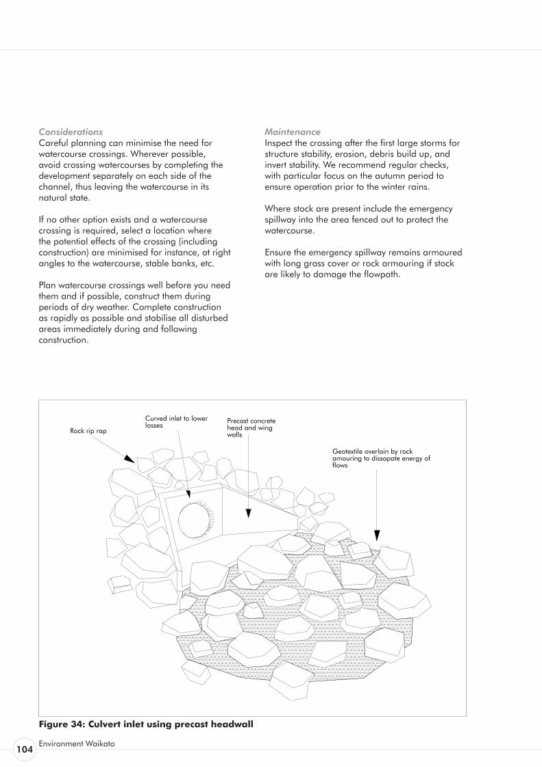
104Environment Waikato
Considerations Careful planning can minimise the need for watercourse crossings. Wherever possible, avoid crossing watercourses by completing the development separately on each side of the channel, thus leaving the watercourse in its natural state.
If no other option exists and a watercourse crossing is required, select a location where the potential effects of the crossing (including construction) are minimised for instance, at right angles to the watercourse, stable banks, etc.
Plan watercourse crossings well before you need them and if possible, construct them during periods of dry weather. Complete construction as rapidly as possible and stabilise all disturbed areas immediately during and following construction.
Maintenance Inspect the crossing after the first large storms for structure stability, erosion, debris build up, and invert stability. We recommend regular checks, with particular focus on the autumn period to ensure operation prior to the winter rains.
Where stock are present include the emergency spillway into the area fenced out to protect the watercourse.
Ensure the emergency spillway remains armoured with long grass cover or rock armouring if stock are likely to damage the flowpath.
Figure 34: Culvert inlet using precast headwall
Rock rip rap Precast concrete head and wing walls
Curved inlet to lower losses
Geotextile overlain by rock amouring to dissapate energy of flows
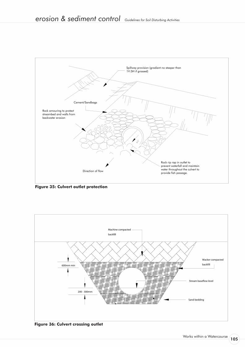
erosion & sediment control Guidelines for Soil Disturbing Activities
Works within a Watercourse 105
Cement/Sandbags
Rock amouring to protect streambed and walls from backwater erosion
Direction of flow
Rock rip rap in outlet to prevent waterfall and maintain water throughout the culvert to provide fish passage.
Spillway provision (gradient no steeper than 1V:5H if grassed)
Figure 35: Culvert outlet protection
Figure 36: Culvert crossing outlet
Stream baseflow level
Sand bedding
Machine compacted
backfill
Wacker compacted
backfill
200 - 300mm
600mm min

106Environment Waikato
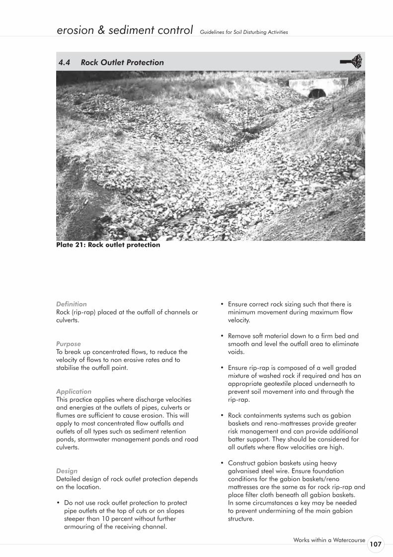
erosion & sediment control Guidelines for Soil Disturbing Activities
Works within a Watercourse 107
Definition Rock (rip-rap) placed at the outfall of channels or culverts.
Purpose To break up concentrated flows, to reduce the velocity of flows to non erosive rates and to stabilise the outfall point.
Application This practice applies where discharge velocities and energies at the outlets of pipes, culverts or flumes are sufficient to cause erosion. This will apply to most concentrated flow outfalls and outlets of all types such as sediment retention ponds, stormwater management ponds and road culverts.
Design Detailed design of rock outlet protection depends on the location.
• Do not use rock outlet protection to protect pipe outlets at the top of cuts or on slopes steeper than 10 percent without further armouring of the receiving channel.
Rock Outlet Protection 4.4
Plate 21: Rock outlet protection
• Ensure correct rock sizing such that there is minimum movement during maximum flow velocity.
• Remove soft material down to a firm bed and smooth and level the outfall area to eliminate voids.
• Ensure rip-rap is composed of a well graded mixture of washed rock if required and has an appropriate geotextile placed underneath to prevent soil movement into and through the
rip-rap.
• Rock containments systems such as gabion baskets and reno-mattresses provide greater risk management and can provide additional batter support. They should be considered for all outlets where flow velocities are high.
• Construct gabion baskets using heavy galvanised steel wire. Ensure foundation conditions for the gabion baskets/reno mattresses are the same as for rock rip-rap and place filter cloth beneath all gabion baskets. In some circumstances a key may be needed to prevent undermining of the main gabion structure.

108Environment Waikato
• Design the structure and use materials within the relevant manufacturer’s and engineering specifications.
• Reno-mattresses may require pinning to the apron of the headwall or the substrate to prevent downstream movement.
• Remember that works within a watercourse such as the placement of rock rip-rap or gabion baskets may require a resource consent from Environment Waikato. Contact us well ahead of time so that any consents needed may be obtained before works are due to start.
Maintenance Once installed, the maintenance requirements of such structures is very low. Inspect after high flows to check scour and dislodgement and make repairs immediately.
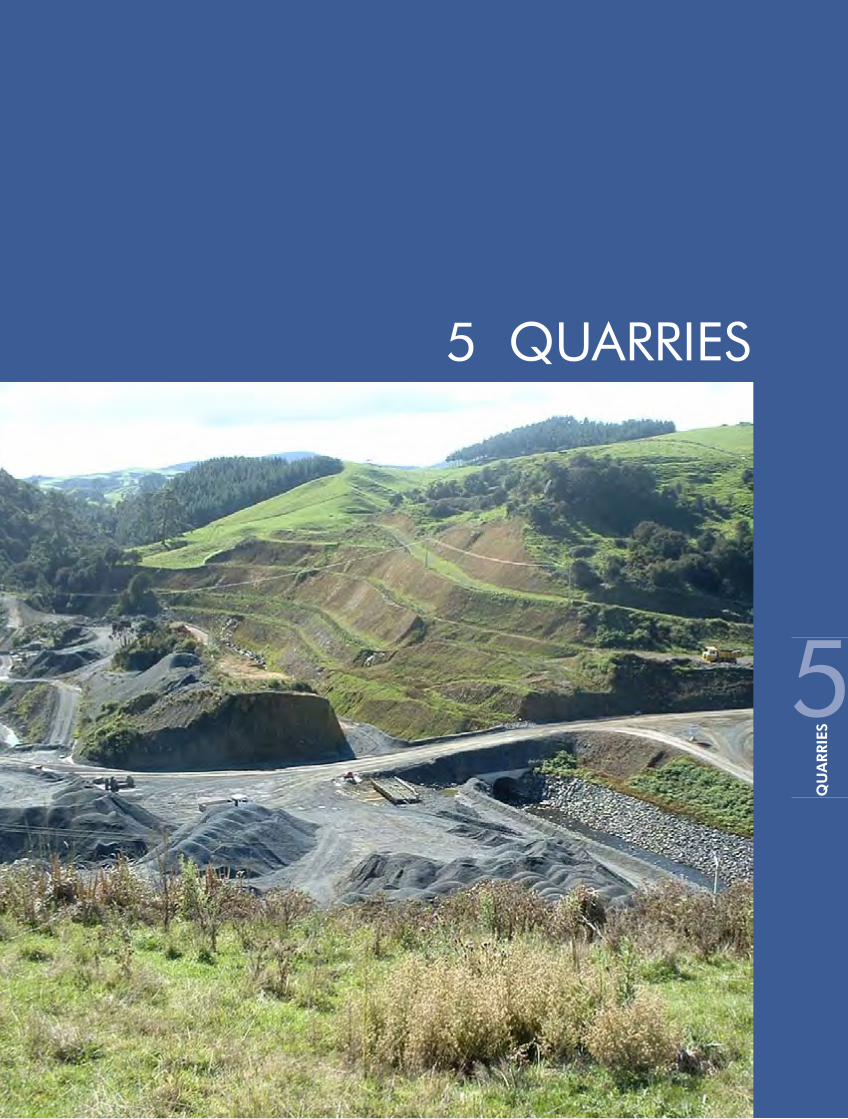

erosion & sediment control Guidelines for Soil Disturbing Activities
Quarries 109
Quarries are potentially a major source of sediment. They are often exposed for long periods of time and the area of bare earth can be considerable. Their continuous operation means that site conditions continually change. Careful planning is required to ensure that the operations are carried out with minimal environmental impact. It is the responsibility of the quarry operator to minimise the adverse environmental effects of the operation.
This section of these guidelines is designed to help quarry operators address soil and water problems which may arise as a result of quarry operations. It should be read in conjunction with Sections 2 and 3 of these guidelines, which detail specific erosion and sediment control practices. Quarries are often required to produce management plans covering the various aspects of their operation. These guidelines will help in the production of such plans.
The following specific issues associated with quarry operations are discussed below: 1. road access 2. stormwater 3. overburden disposal 4. stockpile areas 5. rehabilitation of worked out areas 6. riparian protection areas 7. maintenance schedule for erosion and
sediment control treatment structures.
Road Access Many quarries are serviced by metal roads, used in all weather conditions. Vehicle movements during rain can generate a lot of sediment. These roads, however, are not always within the designated quarry area and therefore are not covered by the Quarry Management Plan. Careful consideration needs to be given to managing roads and traffic. In cases such as these, erosion and sediment control measures need to be installed along roads as outlined in Sections 2 and 3 of these guidelines.
Where possible, incorporate road access into the Quarry Management Plan, ensuring all measures necessary are put in place to protect receiving environments.
Stormwater • CleanRunoff As far as it is possible, divert clean water
flow away from working and bare areas to prevent them from becoming contaminated by sediment. This aids in reducing the volume of contaminated runoff needing to be controlled and treated. Runoff Diversion Channels around the working site, as outlined in Section 2 are the simplest way to deal with the clean runoff.
• ContaminatedRunoff Any runoff from bare areas will collect sediment
and become contaminated. This contaminated runoff, which includes runoff from aggregate wash processes, must be contained and treated in an appropriate manner before being discharged to natural watercourses. The Quarry Management Plan must detail the methods for containment and treatment of all contaminated runoff. Particular attention should be paid to sensitive areas such as permanent watercourses, watercourse crossings and steeply sloping bare areas. Design all structures for the 5 percent AEP rainfall event.
Overburden Disposal Methods of overburden disposal vary for each quarry operation. Overburden removal and disposal sites can be a major source of erosion and sediment discharges from quarries, particularly if the disposal site is not properly located and managed. The Quarry Management Plan for the site should give a reasonable indication of the following:
• The timing and extent of overburden stripping, which will be related to an expected volume and area of extraction.
• The methods to be employed for disposing the overburden.
• Ongoing management of disposal sites, including provision for regular disposal of material trapped in sediment retention ponds.
Quarries5.
110Environment Waikato
If overburden disposal is dealt with in isolation from the Quarry Management Plan, consideration must be given to the following points:
• Selection of disposal site (why the site was chosen).
• Stability of the site and subsequent overburden fill (batter slopes, safety factors, benching, underlying material, drainage).
• Erosion and sediment control measures. • Rehabilitation of disposal site (re-vegetation,
contouring).
Stockpile Areas Stockpile areas include those used for stockpiling both raw or finished quarry products prior to further processing or final despatch. These areas can be a major source of contaminated runoff if not properly controlled. Position stockpiles well away from any watercourses and runoff flow paths.
Rehabilitation of Worked Out Areas Planning for rehabilitation must be an integral part of all quarry operations. A properly planned and implemented rehabilitation programme will reduce the need for expensive ongoing erosion control, and control and treatment of contaminated runoff. The aim of site rehabilitation, whether temporary or permanent, is to maintain the site in a condition such that erosion and contaminated runoff are limited to an acceptable level. The prime areas for consideration are:
• establishing suitable final ground contours• establishing a suitable environment for
vegetation growth• re-vegetating the site with suitable vegetation
cover.
Riparian Protection Areas Riparian protection areas rely on vegetation to provide a buffer between the quarry operations and a water body such as a watercourse or wetland. These margins act as a physical barrier to keep machines away from sensitive areas as well as serving as a last resort sediment trap for diffuse runoff and/or unforeseen discharges. Do not, however, rely on riparian protection areas as a primary sediment control mechanism.
Maintenance Schedule for Erosion and Sediment Control or Treatment Structures Because quarry operations continue over a very long time frame, it is important to develop a maintenance schedule for any control/treatment structures that are put in place. Money spent on designing and constructing control/treatment structures will be wasted if these structures are not adequately maintained.
Properly maintained structures will provide optimum performance at all times, thereby minimising the adverse environmental effects of the quarry operation. Conversely, poorly maintained structures are likely to result in unsatisfactory environmental protection despite being initially well designed and constructed.
Develop a maintenance schedule for the site that clearly indicates what is to be done in terms of visual inspections and maintenance works. Undertake routine maintenance works when they will cause the least possible detrimental environmental effects (either directly or indirectly). For example, do not clean sediment retention ponds during or immediately after rainfall events. To ensure that the operation of the pond is not affected at these critical times, maintenance should be done prior to events.
It is also particularly important that all control/ treatment structures are inspected after significant rainfall events, or during prolonged rainfall, in addition to any regular scheduled inspections.
In the maintenance schedule include a procedure for immediately repairing and remedying any damage caused to control/treatment structures from daily quarry activities.
Within the overall quarry operation, give the inspection and maintenance of control/treatment structures a high priority. Ensure every person involved in the quarry operation is familiar with all aspects of erosion and sediment control on the site, including any special conditions of consents that are relevant, for example, specific water quality sampling requirements.
For all aspects of quarry operations where erosion and sediment controls are required, install the erosion and sediment control practices as specified in these guidelines.
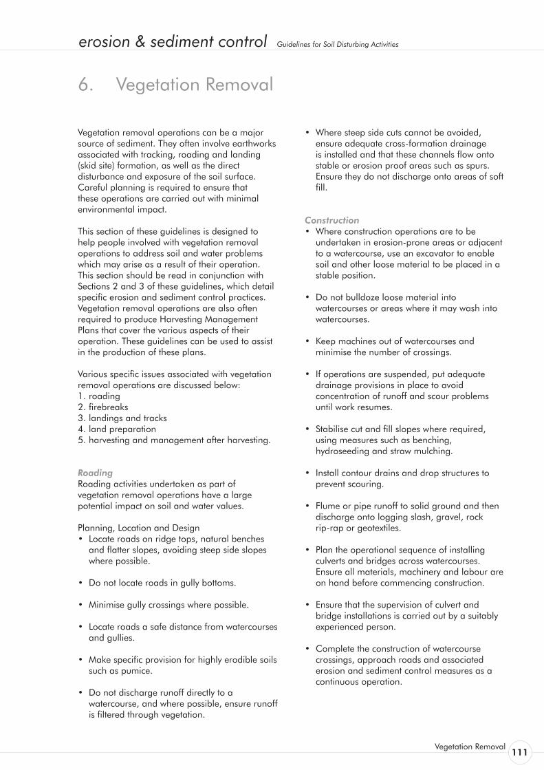
erosion & sediment control Guidelines for Soil Disturbing Activities
Vegetation Removal 111
Vegetation removal operations can be a major source of sediment. They often involve earthworks associated with tracking, roading and landing (skid site) formation, as well as the direct disturbance and exposure of the soil surface. Careful planning is required to ensure that these operations are carried out with minimal environmental impact.
This section of these guidelines is designed to help people involved with vegetation removal operations to address soil and water problems which may arise as a result of their operation. This section should be read in conjunction with Sections 2 and 3 of these guidelines, which detail specific erosion and sediment control practices. Vegetation removal operations are also often required to produce Harvesting Management Plans that cover the various aspects of their operation. These guidelines can be used to assist in the production of these plans.
Various specific issues associated with vegetation removal operations are discussed below: 1. roading 2. firebreaks 3. landings and tracks 4. land preparation 5. harvesting and management after harvesting.
Roading Roading activities undertaken as part of vegetation removal operations have a large potential impact on soil and water values.
Planning, Location and Design • Locate roads on ridge tops, natural benches
and flatter slopes, avoiding steep side slopes where possible.
• Do not locate roads in gully bottoms.
• Minimise gully crossings where possible.
• Locate roads a safe distance from watercourses and gullies.
• Make specific provision for highly erodible soils such as pumice.
• Do not discharge runoff directly to a watercourse, and where possible, ensure runoff is filtered through vegetation.
Vegetation Removal 6.
• Where steep side cuts cannot be avoided, ensure adequate cross-formation drainage is installed and that these channels flow onto stable or erosion proof areas such as spurs. Ensure they do not discharge onto areas of soft fill.
Construction • Where construction operations are to be
undertaken in erosion-prone areas or adjacent to a watercourse, use an excavator to enable soil and other loose material to be placed in a stable position.
• Do not bulldoze loose material into watercourses or areas where it may wash into watercourses.
• Keep machines out of watercourses and minimise the number of crossings.
• If operations are suspended, put adequate drainage provisions in place to avoid concentration of runoff and scour problems until work resumes.
• Stabilise cut and fill slopes where required, using measures such as benching, hydroseeding and straw mulching.
• Install contour drains and drop structures to prevent scouring.
• Flume or pipe runoff to solid ground and then discharge onto logging slash, gravel, rock
rip-rap or geotextiles.
• Plan the operational sequence of installing culverts and bridges across watercourses. Ensure all materials, machinery and labour are on hand before commencing construction.
• Ensure that the supervision of culvert and bridge installations is carried out by a suitably experienced person.
• Complete the construction of watercourse crossings, approach roads and associated erosion and sediment control measures as a continuous operation.
112Environment Waikato
Firebreaks • Locate firebreaks to minimise the possibility of
debris entering watercourses.
• Keep earthworks associated with firebreaks clear of steep drop-offs and watercourses. Consideration must be given to the erosion potential of tracks formed along gully bottoms. These areas should be avoided.
• Maintain firebreaks to a reasonable standard to control runoff, rilling and gully erosion.
• Construct contour drains as required.
• Avoid ponding of water above steep drop-offs and, if ponding occurs, implement an appropriate drainage design to prevent gully erosion.
• At the completion of operations, check firebreaks for any potential erosion problems.
Land Preparation • Planning Plan and implement all land preparation and
forest establishment to match an appropriate proposed method of harvesting.
• Protection Areas (Riparian Margins) Retain or establish protection areas along all
watercourses. Where protection areas do not exist, they can be established in conjunction with the following operations.
- Land clearing or site preparation on areas being converted to production forestry.
- Planting on farm land or similar sites. - Replanting on exotic clear felled areas. - Vegetation removal on terrain which may be
difficult, very steep or erosion prone.
• Re-evaluate all existing protection areas when harvesting or replanting adjacent to production stands.
• Generally, protection areas can be left to regenerate naturally. However, in some cases it may be appropriate to accelerate re-vegetation by actively planting protection species.
• Planting Boundaries When re-planting, establish planting
boundaries back from watercourses in order to minimise potential watercourse damage from future harvesting operations. Establish planting the boundaries on a ‘case by case’ basis with consideration to both topography and soil stability.
• V-Blading/Line Raking Where possible operate across the contour, to
minimise runoff concentration down the blade lines.
Where downhill runs are unavoidable, limit them to 50 m maximum length. Do not attempt these runs on slopes too steep for the tractor to reverse up. Blade or rake at least one line on the contour along the lower boundary of downhill operations to prevent runoff concentration at low points or gully systems. Finish downhill runs well before any fill batter slopes such as landings and access roads.
• Establishing and Tending During establishing and tending stages,
minimise soil loss and prevent contamination of watercourses with chemicals, fertilisers, debris or detritus.
During thinning to waste operations, fell trees away from watercourses where possible.
Harvesting and Management After Harvesting • Planning of Logging Operations Plan all logging operations, particularly the
location of skid tracks and roads, to protect water and soil values.
Off-site adverse effects must be avoided or minimised when determining the ability and management of a catchment to be harvested. When harvesting near sensitive areas, extract towards landings located away from them.
• FellingOperations When trees are being felled within reach of a
watercourse, ensure an experienced feller is in control of the operation. Where possible, fell trees away from watercourses. Extract any trees that have fallen into watercourses before de-limbing and heading. Back pull, or employ other acceptable directional felling techniques to fell problem trees, particularly on steep or
erosion & sediment control Guidelines for Soil Disturbing Activities
Vegetation Removal 113
unstable watercourse faces and edges. Remove all large logging debris from watercourses at the completion of the operation, keeping machinery out of the watercourse.
• ExtractionOperations GroundBasedSystems- Keep tracking and stumping activities to
a practical minimum. Use a few carefully chosen tracks and stay on these rather than taking shortcuts which cause unnecessary ground disturbance.
- Carry logs off the ground or on the machine where possible.
- Keep the machine blade up and do not bulldoze soil and stumps needlessly.
- Do not cross watercourses (other than at approved crossing points) and do not haul along them.
- On soft and/or wet soils or steeper slopes, use low-ground-pressure machines such as flexible-track or wide-tyre skidders.
• CableSystems- Wherecablesystemsareusedinenvironmentallysensitiveareas,keepthesettings small, the haul distances short and the hauling direction uphill wherever practicable. Avoid cross slope haul lines that damage protection areas or sweep slash and soil into watercourses.
- Wheneverpossiblewhenhaulingacrosswatercourses,useasystemsuchasaskylinewhich allows full suspension of logs. Lift logs clearofwatercoursebanksandprotectionareas.
• CleanupOperations On completion of logging operations, carry out
the following procedures: - Remove all temporary crossings. - Construct water cut-offs on skid tracks to
prevent runoff concentration and sediment flow.
- Ensure landings are properly drained and that sediment and debris are unable to directly enter any watercourse.
- Stabilise fill batters on landings and tracks by sowing with suitable grass seed.
- Ensure runoff is channelled safely over batter slopes and onto stable areas.
On all aspects of vegetation removal operations where erosion and sediment controls are required, install the erosion and sediment control measures as specified in these guidelines.
Landings and Tracks Landings and tracks are generally permanent features and therefore require careful location preparation, direction of fall and control of runoff. Skid tracks, while generally more of a temporary feature, also require careful consideration of the above. Any tracking results in concentration of runoff and consequently, an increase in erosion. Minimise erosion by tracking across contours and where possible, locating tracks on ridges rather than in gullies.
Ensure that extraction tracks do not lead directly down towards watercourses where runoff may go directly into the channel.
Where possible try to keep skid tracks and landings at least 20 m away from watercourses.
At the completion of logging operations, construct water cut-offs across skid tracks wherever runoff may be concentrated. Ensure that water cut-offs discharge to solid ground and not to areas of fill.
Keep landings well clear of permanent watercourses. Where no alternative exists, ensure that the watercourse is not obstructed. Form all landings so that surface runoff does not flow down towards or directly into a watercourse. Construct earth bunds along watercourse edge boundaries to prevent debris and sediment from entering watercourses. Extra caution must also be exercised in the planning and construction measures which control water flowing off skid tracks onto landings, so as to minimise water runoff onto the landing.
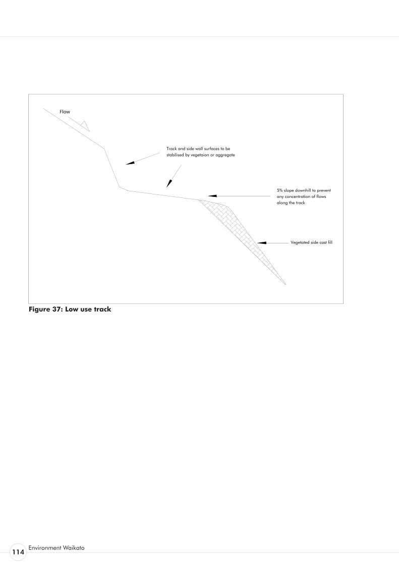
114Environment Waikato
Figure 37: Low use track
Flow
5% slope downhill to prevent any concentration of flows along the track
Vegetated side cast fill
Track and side wall surfaces to be stabilised by vegetaion or aggregate
erosion & sediment control Guidelines for Soil Disturbing Activities
Glossary 115
(AEP) Annual Exceedance Probability A statistical term defining the probability of an event occurring annually. Expressed as a percentage and generally used in hydrology to define rainstorm intensity and frequency. For example, a 5 percent AEP event has a 5 percent chance of being exceeded in any one year. This has replaced the return period concept. A 5 percent AEP event expresses the 20-year return period probability terms.
Anti-seep Collar An impermeable barrier, usually of concrete, constructed at intervals within the zone of saturation along the conduit of a primary outlet pipe to increase the seepage length along the conduit and thereby prevent piping or seepage in the compacted fill material along the outside of the pipe.
Area of Disturbance The area of exposed soil.
Baffles Semi-permeable or solid barriers placed in a sediment retention pond to deflect or regulate flow and effect a more uniform distribution of velocities, hence creating better settling conditions.
Batter A constructed slope of uniform gradient.
Berm Narrow strip beside road.
BPO Best practicable option.
Bulk Earthworks This term is generally used to describe the cut to fill earthworks required to re-grade an area. It also applies to larger scale earthworks such as for building excavations.
Catchment A geographical unit within which surface runoff is carried under gravity by a single drainage system to a common outlet. Also commonly referred to as a watershed or drainage basin.
Channel That part of a watercourse system where normal flow is contained. The channel is generally incised
into the flood plain and for many of the stable stream systems in New Zealand can be defined in capacity as being just able to accommodate the annual return period flow (100 percent AEP) without overtopping.
Also refers to an artificial conduit such as a ditch excavated to convey water.
Channel Stabilisation Stabilisation of the channel profile by erosion control and/or velocity distribution through reshaping, the use of structural linings, mass blocks, vegetation and other measures.
Channel Storage The amount of water temporarily stored in channels while en route to an outlet.
Clay (Soils) A mineral soil consisting of particles less than 0.002 mm in equivalent diameter. A soil texture class.
CleanfillMaterial that when discharged to the environment will have no adverse effect on people or the environment. This includes natural materials such as clay, soil and rock, and other inert materials such as concrete and brick, or mixtures of any of the above. Cleanfill excludes for example:
a) material that has combustible, putrescible or degradable components
b) materials likely to create leachate by means of biological or chemical breakdown
c) any products or materials derived from hazardous waste treatment, hazardous waste stabilisation or hazardous waste disposal practices
d) materials such as medical and veterinary waste, asbestos, or radioactive substances that may present a risk to human health
e) soils or other materials contaminated with hazardous substances or pathogens
f) hazardous substances.
Clean Water Any water that has no visual signs of suspended solids, such as overland flow (sheet or channelled) originating from stable well-vegetated or armoured surfaces.
Glossary7.
116Environment Waikato
Cohesion The capacity of a soil to resist shearing stress, exclusive of functional resistance.
Cohesive Soil A soil that, when unconfined, has considerable strength when air-dried and significant cohesion when submerged.
Compaction For construction work in soils, engineering compaction is any process by which the soil grains are rearranged to decrease void space and bring them into closer contact with one another, thereby increasing the weight of solid material per unit of volume, increasing their shear and bearing strength and reducing permeability.
Concentrated Flow The accumulation of material that has settled because of reduced velocity of the transporting agent (water or wind).
Conduit Any channel intended for the conveyance of water, whether open or closed.
Construction staging The phasing of bulk earthworks to minimise the area of bare earth exposed at any one time.
Contour A line across a slope connecting points of the same elevation.
Contributing Drainage Area All of that drainage area that contributes to the flow into a treatment device. A contributing drainage area can include both clean and sediment-laden water flows. Commonly referred to as the catchment area.
Crimping The embedding of straw mulch into the soil surface by using implements such as a disc cultivator set at zero cut.
Critical 20 Year Return Period Storm A rainfall event that has a 5 percent Annual exceedance probability and a duration equal to the time of concentration.
Cumulative Effect The combination of discrete isolated effects, the sum of which can have a major long term detrimental impact.
Dam A barrier to confine or raise water for storage or diversion, to create a hydraulic head, to prevent gully erosion, or to retain soil, rock or other debris.
Decant Rate The rate at which surface water is decanted from a sediment retention pond.
Deposition The accumulation of sheet flow into discrete rills, gullies or channels, significantly increasing erosive forces.
Detention Dam A dam constructed for the temporary storage of storm flow, which releases the stored water at controlled rates in order to reduce flooding hazard downstream of the dam.
De-watering The removal of impounded water, generally by pumping. Refer sump pit.
Di-ammonium phosphate (DAP) A high percentage nitrogen and phosphate fertiliser suitable for the rapid establishment of grass.
Disturbed Area An area of exposed soil.
Diversion A channel or bunds constructed to convey concentrated flow.
Drainage The removal of excess surface water or ground water from land by means of surface or subsurface drains.
Drainage Basin Refer catchment.
Emergency Spillway A sediment retention pond or dam spillway designed and constructed to discharge flow in excess of the structure’s primary spillway design discharge.
erosion & sediment control Guidelines for Soil Disturbing Activities
Glossary 117
Energy Dissipator A designed device such as an apron of rip-rap or a concrete structure placed at the end of a water conduit such as a pipe, paved ditch or flume for the purpose of reducing the velocity and energy of the discharged water.
Ephemeral Watercourse A watercourse that flows only part of the year; includes overland flowpaths such as grassland swales and dry gullies which only flow during more intensive rainstorms.
Erodible An erodible soil is a soil that is readily entrained (moved) by actions such as rain drop impact, overland flow or wind.
Erosion and Sediment Control Plan (E&SCP) A detailed Plan normally prepared by the Developer’s engineer that details the way erosion is to be minimised and treatment of sediment-laden overland flow is to be undertaken.
Erosion Matting A manufactured matting of either synthetic or natural fibre used to minimise surface erosion and in some cases, promote re-vegetation.
Erosive Refers to the ability of erosional agents such as wind or water to cause erosion. Not to be confused with erodible, as a quality of soil.
Erosive Velocities Velocities that are high enough to wear away the land surface. Exposed soils erode faster than stabilised soils. Erosive velocities vary according to the soil type, slope and structural or vegetative stabilisation used to protect the soil.
Estuary Area where fresh water meets salt water, where the tide meets the river current (such as bays, mouths of rivers, salt marshes and lagoons). Estuaries serve as nurseries and spawning and feeding grounds for large groups of marine life and provide shelter and food for birds and wildlife. The majority of the estuaries in the Auckland Region are low energy systems where sediment readily settles.
Evapotranspiration The sum of surface evaporation and plant transpiration.
Filter Blanket A layer of sand and/or gravel designed to prevent the movement of fine-grained soils.
Fill Earth placed (normally under a strict compaction regime) to raise the land surface.
Filter Fabric A woven or non-woven, water-permeable geotextile made of synthetic products such as polypropylene used for such purposes as preventing clogging of aggregate by fine soil particles. Refer geotextile fabric.
Filter Strip A long, narrow vegetative planting used to retard or collect sediment for the protection of adjacent properties or receiving environments.
Fines (Soil) Generally refers to the silt and clay size particles in soil.
Fire Breaks Specific deforested strips within a forest to act as a barrier in the event of fire.
Flocculation The process whereby fine particles suspended in the water column clump together and settle. In some instances this can occur naturally, such as when fresh clay-laden flows mix with saline water, as occurs in estuaries. Flocculation can be used to promote rapid settling in sediment retention ponds by the addition of flocculating chemicals (flocculants).
Flume A high-velocity, open channel for conveying water to a lower level without causing erosion. Also referred to as a chute.
Gabion Basket A flexible woven-wire basket composed of two to six rectangular cells filled with small stones. Gabions may be assembled into many types of structures such as retaining walls, channel liners, drop structures and groynes.
118Environment Waikato
Geosynthetic Erosion Control Systems (GECS) The artificial protection of erodible channels and slopes using artificial erosion control material such as geosynthetic matting, geotextiles or erosion matting.
Geotextile Fabric A woven or non-woven, impermeable or semi-permeable material generally made of synthetic products such as polypropylene and used in a variety of engineering, stormwater management, and erosion and sediment control applications.
Grade The slope of a road, channel or natural ground.
The finished surface of a channel bed, road bed, top of embankment or bottom of excavation. Any surface prepared for the support of construction like paving or for laying conduit.
To finish the surface of a channel bed, road bed, top of embankment or bottom of excavation.
Gravel Aggregate consisting of mixed sizes of 5 mm to 75 mm particles which normally occur in or near old streambeds and have been worn smooth by the action of water.
Harvesting Management Plans A plan detailing how the forest harvest operation is to be conducted to minimise earth disturbance and to maximise the protection of adjoining land and natural features such as watercourses and native vegetation.
Headwater The source of a watercourse. The water upstream of a structure or point on a watercourse.
Hydrology The science of the behaviour of water in the atmosphere, on the surface of the earth and underground.
Hydroseeding The spraying of a slurry of seed, fertiliser and paper or wood pulp over a surface to be re-vegetated.
Impervious Not allowing infiltration of water.
Landings Forestry - a log production and assembly area.
Level Spreader A device used to convert concentrated flow into sheet flow.
Mitigation Measures taken to off-set adverse environmental effects caused by soil disturbing activities.
Mulch Covering on surface of soil to protect it and enhance certain characteristics, such as protection from rain drop impact and improving germination.
Overburden (Quarries) Unusable soil/rock stripped from above suitable production material.
Overland Flow Path The route of concentrated flow.
Perennial Stream A stream that maintains water in its channel throughout the year or maintains a series of discrete pools that provides habitats for the continuation of the aquatic ecosystem.
Permeability (Soil) The rate at which water will move through a saturated soil.
Permitted Activity An activity that does not exceed the thresholds specified by a Regional or District Plan whereby a resource consent is required. However permitted activities must meet certain performance standards in terms of minimising adverse effects.
Pervious Allowing movement of water.
Poly Aluminium Chloride (PAC)A long chain chemical that is used as a flocculent in certain situations.
Primary Spillway The riser inlet within a sediment retention pond.
erosion & sediment control Guidelines for Soil Disturbing Activities
Glossary 119
Quarry Management PlansA plan detailing how a quarry operation is to be conducted to minimise earth disturbance, to maximise the protection of adjoining land and natural features such as watercourses and native vegetation, and to minimise the effect on adjoining residents and/or landowners.
Rainfall Intensity The volume of rainfall falling in a given time. Normally expressed as mm/hour.
Rehabilitation Restoration to as near to pre-disturbance conditions as possible. This may entail such measures as revegetation for erosion control, enhancement planting, modification and armouring of watercourses.
Reno Mattress A shallow (300 - 500 mm deep), wide, flexible woven-wire basket composed of two to six rectangular cells filled with small stones. Often used at culvert inlets and outlets to dissipate energy and prevent channel erosion.
Return Period The statistical interpretation of the frequency of a given intensity and duration rainstorm event. Refer AEP.
Re-vegetation The establishment of vegetation to stabilise a site.
Riparian Protection Area An area adjacent to a watercourse designated as a non-disturbance zone to provide a buffer between receiving environments (for example, watercourses) and the area of operation.
Riser In a sediment retention pond, a vertically placed pipe to which decant pipes are attached, which forms the inlet to the primary spillway.
Saturation Point In soils, the point at which a soil or an aquifer will no longer absorb any amount of water without losing an equal amount.
Scarified Shallow subsurface disturbance with a tine implement to provide surface roughening. Used before topsoiling and re-vegetation.
Scour The erosive or digging action of flowing water; the downward or lateral erosion caused by water. Channel-forming stream scour is caused by the sweeping away of mud and silt from the outside bank of a curved channel (meander), particularly during a flood.
Sediment Solid material, both mineral and organic, that is in suspension, is being transported or has been moved from site of origin by air, water, gravity or ice and has come to rest on the earth’s surface either above or below water.
Sediment Delivery Ratio The proportion of the soil eroded from within a catchment area that actually reaches sediment treatment controls or water bodies.
Sediment Texture The relative proportions of different sized of sediment and soil particles that can be separated by screening. The size of sediment particulate. Refer soil texture.
Sediment YieldThe quantity of sediment discharged from a particular site or catchment in a given time, measured in dry weight or by volume. When erosion and sediment control measures are in place, sediment yield is the sediment discharged from the site after passing through those measures.
Settling The downward movement of suspended solids through the water column.
Shear Strength The ability to resist shear (slip) forces.
Sheet flow Shallow dispersed overland flow.
Shutter Boards Plywood or similar sheeting supported by light timber framing normally used for boxing concrete forms.
Silt A soil consisting of particles between 0.05 and 0.002 mm in equivalent diameter. A soil textural class.
120Environment Waikato
Silt Loam A soil textural class containing a large amount of silt and small quantities of sand and clay.
Silty Clay A soil textural class containing a relatively large amount of silt and clay and a small amount of sand.
Slash Branches trimmed from production logs.
Soil The unconsolidated mineral and organic material on the surface of the earth that serves as a natural medium for the growth of land plants.
Earth and rock particles resulting from the physical and chemical disintegration of rocks, which may or may not contain organic matter. Includes fine material (silts and clays), sand and gravel.
Soil Structure Soil structure reflects the pore space within a soil available for aeration and storage of water. It is a measure of bulk density and as a rule the higher the soil bulk density the poorer the structure. The combination or arrangement of primary soil particles into secondary particles, units or peds. Good soil structure is important for plant growth.
Soil Texture The relative proportions of various particle sizes in a soil material. Refer sediment texture.
Spreader (Hydraulics) A device for distributing water uniformly in or from a channel.
Stabilisation Providing adequate measures, vegetative and/or structural that will protect exposed soil to prevent erosion.
Stabilised Area An area sufficiently covered by erosion-resistant material such as a good cover of grass, or paving by asphalt, concrete or aggregate, in order to prevent erosion of the underlying soil.
Subsoil The horizons of soils with distinct profiles. In soils with weak profile development, the subsoil can be defined as the soil below the ploughed soil (or its equivalent of surface soil), in which roots normally grow.
Surface Runoff Rain that runs off rather than being infiltrated or retained by the surface on which it falls.
Surface Water All water with its surface exposed to the atmosphere.
Suspended Solids Solids either floating or suspended in water.
Swale A constructed elongated depression in the land surface that can be seasonally wet, is usually heavily vegetated, and is normally without flowing water. Swales conduct stormwater into primary drainage channels and can provide some ground water recharge.
Tackifier A compound that is added to straw mulch to bind it together and prevent it being blown around by the wind.
Temporary Watercourse Crossing A stable watercourse crossing that is installed for the duration of an operation and is removed in its entirety at the completion of the operation.
Tensile Strength Resistance to elongation and tearing.
Time of Concentration The time for runoff to flow from the most remote part of the drainage area to the outlet.
Toe (of Slope) Where the slope stops or levels out. Bottom of the slope.
Topsoil Fertile or desirable soil material (suitable organic and structural properties) used to top-dress roadbanks, subsoils, parent material etc to provide a suitable medium for plant growth.
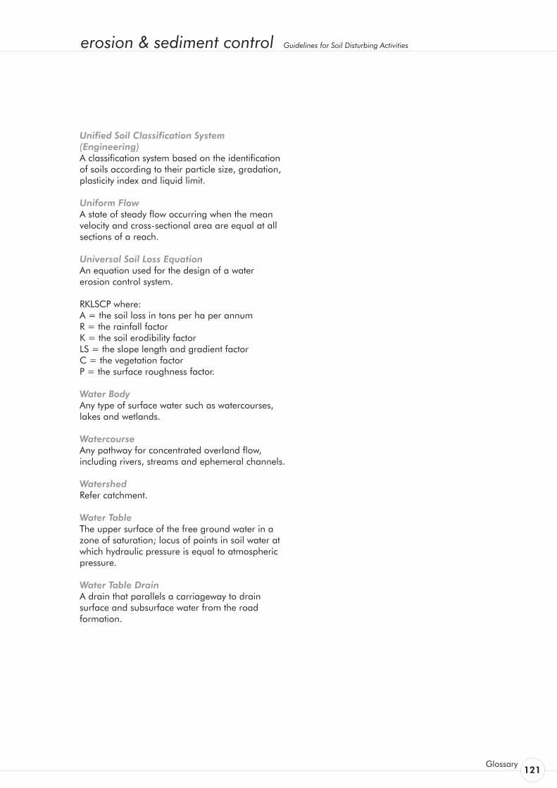
erosion & sediment control Guidelines for Soil Disturbing Activities
Glossary 121
Unified Soil Classification System (Engineering) A classification system based on the identification of soils according to their particle size, gradation, plasticity index and liquid limit.
Uniform Flow A state of steady flow occurring when the mean velocity and cross-sectional area are equal at all sections of a reach.
Universal Soil Loss Equation An equation used for the design of a water erosion control system.
RKLSCP where: A = the soil loss in tons per ha per annum R = the rainfall factor K = the soil erodibility factor LS = the slope length and gradient factor C = the vegetation factor P = the surface roughness factor.
Water Body Any type of surface water such as watercourses, lakes and wetlands.
Watercourse Any pathway for concentrated overland flow, including rivers, streams and ephemeral channels.
Watershed Refer catchment.
Water Table The upper surface of the free ground water in a zone of saturation; locus of points in soil water at which hydraulic pressure is equal to atmospheric pressure.
Water Table Drain A drain that parallels a carriageway to drain surface and subsurface water from the road formation.

122Environment Waikato
erosion & sediment control Guidelines for Soil Disturbing Activities
Glossary 123
Auckland Regional Council. 1995:ProposedRegionalPlan:SedimentControl. Auckland Regional Council, Auckland
Auckland Regional Council. 1994: StormsedimentYieldsfromBasinswithVariousLandusesinAucklandArea. Auckland Regional Council Technical Publication No. 51, Auckland Regional Council, Auckland.
Auckland Regional Council, 1995: TheEnvironmentalImpactsofUrbanStormwaterRunoff. Auckland Regional Council Technical Publication No. 53. Auckland Regional Council, Auckland.
Auckland Regional Council, 1996: TheEnvironmentalImpactsofAcceleratedErosionandSedimentation. Auckland Regional Council Technical Publication No. 69, Auckland Regional Council, Auckland.
Department of Natural Resources and Environmental Control, Delaware, United States, 1989: Delaware ErosionandsedimentControlHandbook. Department of Natural Resources and Environmental Control, Delaware.
Environment B.O.P., 1993: ForestOperationsGuidelines. Environment B.O.P. Guideline, Environment B.O.P., Whakatane
Environment B.O.P. 1996: ErosionandSedimentControlGuidelinesforEarthworks. Environment B.O.P. Guideline No. 1, Version 2, Environment B.O.P., Whakatane
Environment B.O.P. 1994: Erosion and Sediment Control Guidelines for Quarries. Environment B.O.P. Guideline No. 2, Environment B.O.P., Whakatane
Environment Protection Section, Australian Capital Territory Government, Australia, 1989: Guidelines for ErosionandSedimentControlonBuildingSites.Australian Capital Territory Government, Canberra
Environment Waikato, 1995: DesignGuidelinesforEarthworks,TrackingandCrossings.Environment Waikato Technical Publication No. 1995/8, Environment Waikato, Hamilton
Goldman, S.J. Jackson, K, Bursztynsky, T.A. 1986: ErosionandSedimentControlHandbook.McGraw-Hill, New York
Herald, J.R. 1989: Hydrological Impacts Of Urban Development In The Albany Basin, Auckland. PhD Thesis, University of Auckland
Maryland Department for the Environment, Maryland, United States, 1994: MarylandStandardsandSpecifications for Soil Erosion and Sediment Control. Maryland Department for the Environment, [Baltimore, Md.]
New South Wales Department of Housing, Australia, 1993: SoilandWaterManagementforUrbanDevelopment . New South Wales Department of Housing, [Sydney]
New Zealand Logging Industry Research Organisation, 1993: NewZealandForestCodeofPractice.New Zealand Logging Industry Research Organisation, [Rotorua]
State of North Carolina, United States, 1988: ErosionandSedimentControlPlanningandDesignManual.State of North Carolina, [Raleigh, N.C.]
USDA-Soil Conservation Service, Syracuse, New York, 1991: NewYorkGuidelinesforUrbanErosion&Sediment Control. USDA-Soil Conservation Service, New York
Winter, R, 1998: Predicting sediment Yield During the Earthworks Development Stage of a Subdivision, Auckland, and Assessment of the Efficiency of a sediment retention pond. MSc Thesis, University of Waikato, Hamilton
References

124Environment Waikato
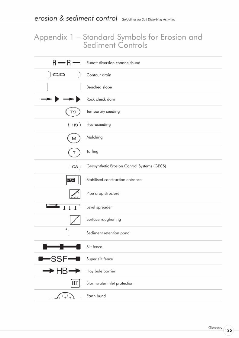
erosion & sediment control Guidelines for Soil Disturbing Activities
Glossary 125
Runoff diversion channel/bund
Contour drain
Benched slope
Rock check dam
Temporary seeding
Hydroseeding
Mulching
Turfing
Geosynthetic Erosion Control Systems (GECS)
Stabilised construction entrance
Pipe drop structure
Level spreader
Surface roughening
Sediment retention pond
Silt fence
Super silt fence
Hay bale barrier
Stormwater inlet protection
Earth bund
Appendix 1 – Standard Symbols for Erosion and Sediment Controls

126Environment Waikato
Sump/sediment pit
Temporary watercourse crossing
Temporary watercourse diversion
Rock outlet protection
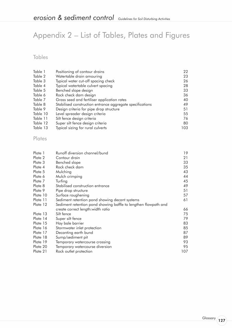
erosion & sediment control Guidelines for Soil Disturbing Activities
Glossary 127
Tables
Table 1 Positioning of contour drains 22Table 2 Watertable drain amouring 23Table 3 Typical water cut-off spacing check 26Table 4 Typical watertable culvert spacing 28Table 5 Benched slope design 33Table 6 Rock check dam design 36Table 7 Grass seed and fertiliser application rates 40Table 8 Stabilised construction entrance aggregate specifications 49Table 9 Design criteria for pipe drop structure 51Table 10 Level spreader design criteria 55Table 11 Silt fence design criteria 76Table 12 Super silt fence design criteria 80Table 13 Typical sizing for rural culverts 103
Plates
Plate 1 Runoff diversion channel/bund 19Plate 2 Contour drain 21Plate 3 Benched slope 33Plate 4 Rock check dam 35Plate 5 Mulching 43Plate 6 Mulch crimping 44Plate 7 Turfing 45Plate 8 Stabilised construction entrance 49Plate 9 Pipe drop structure 51Plate 10 Surface roughening 57Plate 11 Sediment retention pond showing decant systems 61Plate 12 Sediment retention pond showing baffle to lengthen flowpath and create correct length:width ratio 66Plate 13 Silt fence 75Plate 14 Super silt fence 79Plate 15 Hay bale barrier 83Plate 16 Stormwater inlet protection 85Plate 17 Decanting earth bund 87Plate 18 Sump/sediment pit 89Plate 19 Temporary watercourse crossing 93Plate 20 Temporary watercourse diversion 95Plate 21 Rock outlet protection 107
Appendix 2 – List of Tables, Plates and Figures

128Environment Waikato
Figures
Figure 1 Types of erosion common in the Waikato region 10Figure 2 Clean water diversion channel 20Figure 3 Runoff diversion channel 20Figure 4 Contour drain 22Figure 5 Watertable drain 24Figure 6 Water cut-offs 26Figure 7 Watertable culverts 28Figure 8 Soakholes 29Figure 9 Benched slope 34Figure 10 Rock check dam 36Figure 11 Geotextile laid on slope 48Figure 12 Geotextile at culvert outlet 48Figure 13 Stabilised construction entrance 50Figure 14 Pipe/flume drop structures 53Figure 15 Flume design specifications (for catchments up to 0.5 ha) 53Figure 16 Level spreader 56Figure 17 Tracking 58Figure 18 Pond level spreader 65Figure 19 Sediment retention pond for catchments up to 1.5 ha 69Figure 20 Sediment retention pond for catchments between 1.5 and 3 ha 70Figure 21 Sediment retention pond for catchments between 3 and 5 ha 71Figure 22 Sediment retention pond - decant detail 72Figure 23 Sediment retention pond 73Figure 24 Silt fence 77Figure 25 Super silt fence 81Figure 26 Hay bale barrier 84Figure 27 Stormwater inlet protection - filter media design 86Figure 28 Decanting earth bunds 88Figure 29 Sump/sediment pit 90Figure 30 Temporary watercourse diversion works sequence 96Figure 31 Temporary watercourse diversion dam detail 97Figure 32 Bridge plan view 102Figure 33 Small bridge installation 102Figure 34 Culvert inlet using precast headwall 104Figure 35 Culvert outlet protection 105Figure 36 Culvert crossing outlet 105Figure 37 Low use track 114

Environment Waikato, 401 Grey Street, PO Box 4010, Hamilton East.Environment Waikato’s Freephone 0800 800 401 www.ew.govt.nz
This publication was made possible by Environment Waikato Rates