erection of skewed bridges: keys to an effective projecterection of skewed bridges: keys to an...
TRANSCRIPT

Erection of Skewed Bridges: Keys to an Erection of Skewed Bridges: Keys to an Effective ProjectEffective Project
Bob Cisneros, P.E.Chief Engineer
High Steel Structures Inc.

CASE STUDY 1 CASE STUDY 2 CASE STUDY 3
IntroductionIntroductionSR 0028 OVER CSX RRErector: Alvarez, Inc./High Steel Joint effort
HSSI Job No. PA 3127
I-87 NB Connector over I-287 EBErector: Yonkers Contracting Co.
HSSI Job No. NY 01066
SR 0031 over PA TurnpikeSomerset Co., PA
Erector: High Steel Structures, Inc.
HSSI Job No. PA 01004
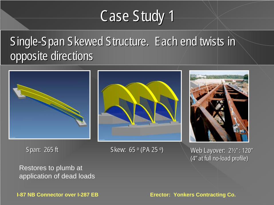
SingleSingle--Span Skewed Structure. Each end twists in Span Skewed Structure. Each end twists in opposite directionsopposite directions
I-87 NB Connector over I-287 EB Erector: Yonkers Contracting Co.
Span: 265 ftSpan: 265 ft
Case Study 1Case Study 1
Restores to plumb at application of dead loads
Skew: 65 Skew: 65 oo (PA 25 (PA 25 oo)) Web Layover: Web Layover: 22½”½” : 120: 120””(4(4”” at full noat full no--load profile)load profile)

LONG-SPAN, DEEP, HIGHLY SKEWED STRUCTURES TEND TO UN-TWIST AS DEADLOAD DEFLECTIONS OCCUR.
I-87 NB Connector over I-287 EB Erector: Yonkers Contracting Co.WEB LAYOVER: 4”: 10 ft (shored to no-load)
YELLOW = TWISTED AT ERECTION (STEEL DL PROFILE)BLUE = PLUMB UPON APPLICATION OF DEADLOADS
SHORED TO DEVELOPERECTED PROFILE

Steel Dead Load
Skewed Bridge ErectionSkewed Bridge Erection
Source: AASHTO/NSBA Steel Bridge Collaboration G12.1-2003, Fig. 1.6.1.BGuidelines for Design for Constructibility (see www.steelbridges.org)

Skewed Bridge ErectionSkewed Bridge Erection
Complete Dead Load

Rte 9 over Connecticut River(New Hampshire & Vermont)Erector: Cianbro Corp.
Twist:15mm (5/8”+)
Twisted Arch Lateral Bracing
Camber:65mm (2 1/2”+)
LB1,2
LB
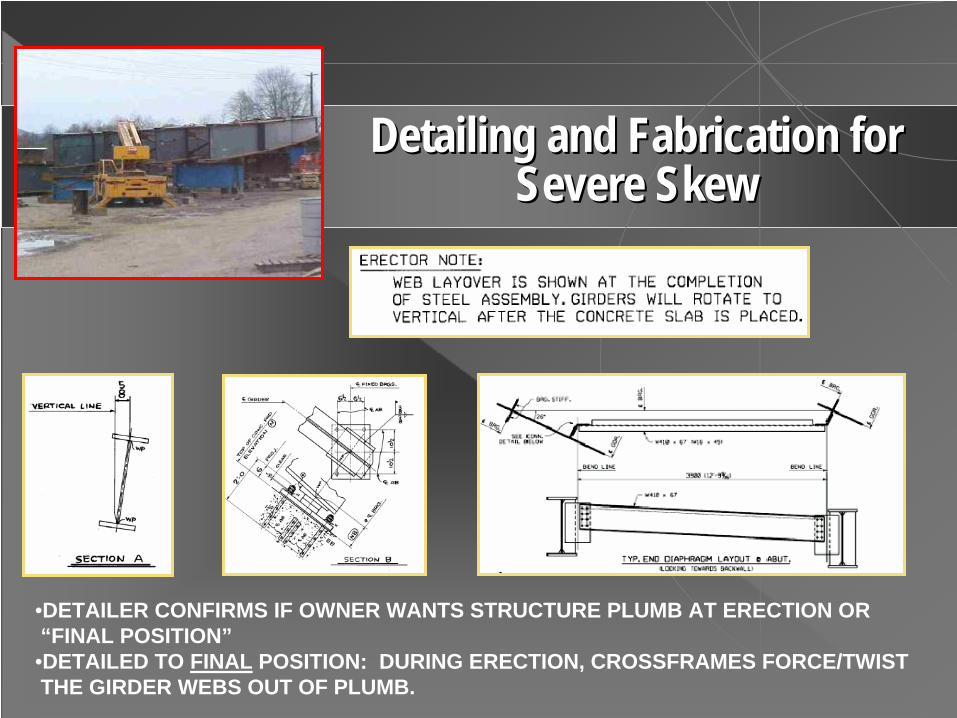
Detailing and Fabrication for Detailing and Fabrication for Severe SkewSevere Skew
•DETAILER CONFIRMS IF OWNER WANTS STRUCTURE PLUMB AT ERECTION OR “FINAL POSITION”•DETAILED TO FINAL POSITION: DURING ERECTION, CROSSFRAMES FORCE/TWIST THE GIRDER WEBS OUT OF PLUMB.

GIRDER WEB LAYOVER IS COMPUTED PURELY AS A GEOMETRIC EFFECT, BASED ON:
•Span, L•Skew, Θ•Dead Load Camber (especially, concrete DL), δCONC•Girder Depth, D
GIRDER END ROTATION IS COMPUTED. Ref. NYSDOT’s Elastomeric Bearing Design Manual (1979), p. 15:
ΘSTEEL =( 4δSTEEL) /L ; similarly, ΘCONC α δCONC
NEXT, BASED UPON ROTATION & SKEW, THE OUT-OF-PLAN LAYOVER OF THE WEBS IS COMPUTED AT SUPPORTS (OPPOSITE SENSE AT ABUTMENTS). IF COMPUTED TO ACCOMMODATE SLAB DL: L.O. = { SIN [ Tan-1(Θ
CONC ) ] x Depth }/Tan (Skew)
ASSUMPTIONS:•THE GIRDERS ARE FLEXIBLE ALONG THEIR SPANS, SO THE BRIDGE CROSS-SECTION AT DIAPHRAGM LINES RETAINS ITS INTEGRITY•SIMILAR TO THE CHICAGO TRUSS ERECTION METHOD, WHERE:
“… (TRUSS) MEMBERS, AS ERECTED UNDER A NO STRESS (OR PRACTICALLY SO) CONDITION, MUST BE BENT AND FORCED TO FIT THE END CONNECTIONS, THUS INTRODUCING AN INITIAL REVERSE SECONDARY STRESS WHICH WILL THEORETICALLY DISAPPEAR WHEN THE STRUCTURE ASSUMES THE LOADING FOR WHICH IT IS CAMBERED”. (AREMA Ch.15, Sect 9.3.2.7)
FOR A SIMPLE SPAN, SKEWED BRIDGE, DETAILING TO FINAL POSITION CREATES A TWIST IN THE GIRDERS AT TIME OF ERECTION, WHICH RELAXES UPON APPLICATION OF CONCRETE DEADLOADS (Like wringing a towel).
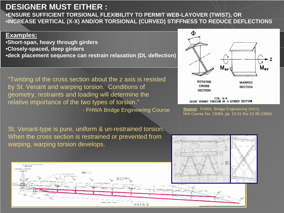
DESIGNER MUST EITHER : •ENSURE SUFFICIENT TORSIONAL FLEXIBILITY TO PERMIT WEB-LAYOVER (TWIST), OR•INCREASE VERTICAL (X-X) AND/OR TORSIONAL (CURVED) STIFFNESS TO REDUCE DEFLECTIONS
Examples:•Short-span, heavy through girders•Closely-spaced, deep girders•deck placement sequence can restrain relaxation (DL deflection)
“Twisting of the cross section about the z axis is resisted by St. Venant and warping torsion. Conditions of geometry, restraints and loading will determine the relative importance of the two types of torsion.”
- FHWA Bridge Engineering Course Source: FHWA, Bridge Engineering (Vol I), NHI Course No. 13064, pp. 13-31 thu 13-38 (1994).
End CF Int CF
St. Venant-type is pure, uniform & un-restrained torsion. When the cross section is restrained or prevented from warping, warping torsion develops.

Two EqualTwo Equal--span Skewed Structure. Each Span Twists in span Skewed Structure. Each Span Twists in Opposite Directions Centered About the Parallel PierOpposite Directions Centered About the Parallel Pier
SR 0031 over PA Turnpike Somerset Co., PA Erector: High Steel Structures Inc.
Spans: Spans: 161 ft each161 ft each
Skew: Skew: 70 70 oo (PA 20 (PA 20 oo))
Web Layover: Web Layover: 1 1 ½”½” : 48: 48””
Case Study 2Case Study 2
Restores to plumb at application of dead loads

< 300 ft SPAN, 60o + REASONABLE (65o + FOR 200 thru 250 ft) • Possibly higher for shorter spans• Check bearing rotational limit
D
ΘXY
3) Curved & skewed •L = 110 ft •R=400 ft• ΘXY =65o
2) Two span continuous•L = 160 ft • ΘXY =70o
1) Long-span (single)•L = 270 ft • ΘXY =65o
4) Skewed widening•L = 230 ft • ΘXY =75o
SAMPLE COMPUTATIONS
General, Practical Skew Limits:General, Practical Skew Limits:
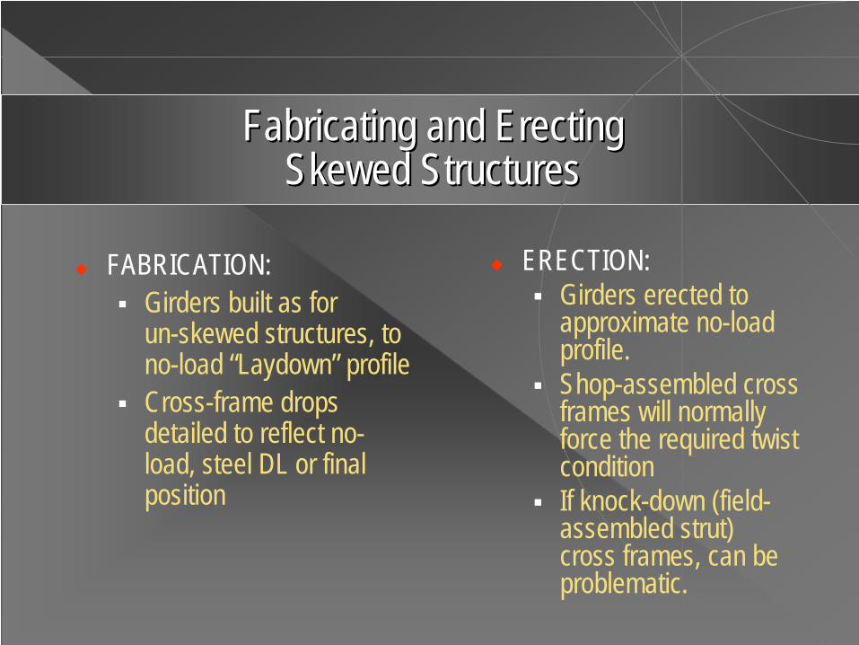
Fabricating and Erecting Fabricating and Erecting Skewed StructuresSkewed Structures
FABRICATION:Girders built as for un-skewed structures, to no-load “Laydown” profileCross-frame drops detailed to reflect no-load, steel DL or final position
ERECTION:Girders erected to approximate no-load profile.Shop-assembled cross frames will normally force the required twist conditionIf knock-down (field-assembled strut) cross frames, can be problematic.

Cross Frame ConnectionsCross Frame Connections
preferred (by fabricators) 20o maximum skew

Note: In the intermediate cross frame detail shown,Dimension A Note: In the intermediate cross frame detail shown,Dimension A is the is the drop (usually tabulated beneath the detail for similar cross fradrop (usually tabulated beneath the detail for similar cross frames.)mes.)
“DROP”

Skewed connection parts can be complicated, especially Skewed connection parts can be complicated, especially when combined with knockwhen combined with knock--down down crossframescrossframes..

REFERENCE ONLY
Erecting HighlyErecting Highly--Skewed StructuresSkewed Structures
TOWERS & TIETOWERS & TIE--DOWNS FACILITATE TWISTDOWNS FACILITATE TWIST
REFERENCE ONLY

••Asymmetrical, continuous flared structure Asymmetrical, continuous flared structure ••subsub--girders framed rigidly into main girders at narrow spacinggirders framed rigidly into main girders at narrow spacing••vertical sagvertical sag--curvecurve••radius: 1,000 ft+/radius: 1,000 ft+/-- (varies, chorded)(varies, chorded)
Spans: 130 ft Spans: 130 ft --130 ft130 ft
Case Study 3Case Study 3
Skew: 64 Skew: 64 oo (PA 26 (PA 26 oo), & varies), & varies Web Layover: Web Layover: 1 1 ½”½” max : 4 ftmax : 4 ft””
SR 0028 over CSX RR, Allegheny County, PA Erector: Alvarez, Inc./HSSI joint effort
Combining Curvature, Severe Skew Combining Curvature, Severe Skew & Stiffness Successfully.& Stiffness Successfully.

WHERE RESTRAINT BY CLOSELY SPACED DIAPHRAGMS WAS ANTICIPATED, CONNECTIONS WERE LEFT SNUG TIGHT UNTIL AFTER DECK POUR (UTILIZED O.S.H. AT THE DIAPHRAGM PLY OF CONNECTION).
Snug-tight locations at time of pourWEB LAYOVER: 2 ¼”+/- MAX (varies)
SNUG-TIGHT
SIMPLE SPAN SUB-GIRDERS FRAMED INTO CONTINUOUS MAIN GIRDERS NEAR 0.6L2 (MAX M+). DESIGNER BALANCED RELATIVE STIFFNESSES OF ADJACENT GIRDERS VIA 3DFE MODEL, TO MINIMIZE DIFFERENTIAL DEFLECTION.

Sub-to-main girder connection Minor, localized mis-alignmentSub-girder SG1
Through effective communication among key parties on the project, only two holes (shown below) failed to come into full alignment.
RELATIVE DL DEFLECTIONS (4 ½” MAXIMUM) BETWEEN THE CLOSELY SPACED SUB- GIRDERS AND MAIN GIRDERS.

PADOT BRG CONST. TOLERANCE
SETTING STEELSETTING STEEL
STRUCTURE ERECTEDSETTING SUB-GIRDER (FASCIA, SG1)
SETTING SPAN 1 (EASIER)
WEB-LAYOVER

Robert A. Cisneros, P.E.Chief Engineer
1770 Hempstead Road P.O. Box 10008Lancaster, PA 17605-0008
(717)293-4086 Fax (717)[email protected] www.highsteel.com
Thank you for your attention.
Long Island Expwy over Cross-Island ParkwayNYSDOT Contract D258437Contractor: Perini Corp.
QUESTIONS?
Curved, FCM Trapezoidal Box GirdersRadius = 325 ft (min.)