equipment equipo operation manual manual de operación rev b shot miser... · equipment equipo...
TRANSCRIPT
EQUIPMENTEQUIPOOperation ManualManual de Operación
Loctite Shot Miser™ Dispense SystemEquip Dosificador Shot Miser™Part Number / Numero de Parte 98116
0.2
OMRON H3CR
OUT
POWER Regulado
0min
1.2
0.40.6
0.8
1.0
MODE
Manual
A
Timed
Shot Miser™Valve Controller
Controlador De Válvula# 98079
Dispense TimeTiempo De Dosificación
Shot Miser™Dispense Valve
Válvula Dosificadora# 98085
Henkel Loctite Corp.Air Cylinder
Cilindro De Aire# 986131
Vari-Drop™ Valve / Válvula:# 97132Air Cylinder / Cilindro De Aire:# 986131
Replacement Parts:Refacciones:
Table of Contents
1. PLEASE OBSERVE THE FOLLOWING __________________________________ 31.1 EMPHASIZED SECTIONS ____________________________________________________________31.2 FOR YOUR SAFETY ________________________________________________________________31.3 UNPACKING AND INSPECTION________________________________________________________41.4 ITEMS SUPPLIED __________________________________________________________________41.5 FEATURES _______________________________________________________________________41.6 USAGE _________________________________________________________________________4
2. DESCRIPTION _______________________________________________________ 52.1 OPERATING ELEMENTS AND CONNECTIONS _____________________________________________52.2 THEORY OF OPERATION_____________________________________________________________6
3. TECHNICAL DATA___________________________________________________ 6
4. INSTALLATION ____________________________________________________ 74.1 MOUNTING ______________________________________________________________________74.2 CONNECTING AIR LINE______________________________________________________________84.3 PRODUCT SUPPLY TUBE_____________________________________________________________84.4 INSTALLING THE ANTI-BUBBLER ________________________________________________84.5 DISPENSE TIP_____________________________________________________________________8
5. OPERATIONS ______________________________________________________ 85.1 PRIMING THE VALVE ______________________________________________________________ 85.2 ADJUSTING THE AMOUNT OF LOCTITE® PRODUCT DISPENSED______________________________ 8
6. MAINTENANCE AND CLEANING ____________________________________ 96.1 CLEANING________________________________________________________________________96.2 MAINTENANCE ___________________________________________________________________96.2.1 Procedure Replacing Vari-Drop and Air Cylinder_____________________________________ 96.2.2 Disasemble the Loctite® Vari-Drop________________________________________________ 96.2.3 Reassemble the Loctite® Vari-Drop_______________________________________________ 11
7. TROUBLESHOOTING ______________________________________________ 13
8. SPARE PARTS AND ACCESSORIES __________________________________ 148.1 SPARE PARTS ___________________________________________________________________ 148.2 ACCESSORIES ___________________________________________________________________14
9. WARRANTY______________________________________________________ 16
1 Please Observe The Following
1.1 Emphasized Sections Warning!
Refers to safety regulations and requires safety measures that protect the operator or otherpersons from injury or danger to life.
Caution!
Emphasizes what must be done or avoided so that the unit or other property is not damaged.
NoticeGives recommendations for better handling of the unit during operation or adjustment as well asfor service activities.
1.2 For Your Safety Warning!
OBSERVE ALL WARNINGS. READ and UNDERSTAND all instructions in the manual beforeattempting to install and operate this equipment.
This equipment has been designed and tested for use with Loctite products that can be dispensedusing time and pressure. Products can have a viscosity of up to 80,000 centipoise.
DO NOT USE equipment for other than intended use.
BE SURE that all adhesives, solvents, or fluids used are chemically compatible with the wetted partsof the equipment.
ALWAYS OBTAIN AND READ the Material Safety Data Sheet(s) before using adhesives, solvents,or any other chemicals in this equipment. COMPLY with ALL WARNINGS and SAFETYINSTRUCTIONS AS STATED.
ALWAYS WEAR protective eyewear, gloves, clothing, and respirator as recommended in thismanual or the Material Safety Data Sheet(s).
Any misuse of the equipment or accessories, such as over pressurizing, modifying parts, usingincompatible chemicals, adhesives, or worn, damaged or not recommended parts, can cause rupture orbreakage and result in fluid injection, splashing in the eyes or on the skin, or other serious injury orproperty damage.
NEVER alter or modify any part of this equipment. Doing so could result in a malfunction.
CHECK the equipment regularly and repair or replace worn or damaged parts immediately.
NEVER exceed the recommended working pressure or the maximum air inlet pressure stated on theequipment or in the manual.
Properly ground all electrical components as recommended in the manual or technical data sheet.
Always KEEP HANDS and FINGERS away from moving parts to reduce the risk of injury.
ALWAYS RELIEVE any pressure and turn off all power sources when checking or servicing anypart of the equipment to reduce the risk of serious injury.
RETAIN THIS MANUAL FOR FUTURE REFERENCE.

1 Please Observe The Following (Continued)
1.3 Unpacking and Inspection
Carefully unpack system components and examine the items contained in the carton. Inspect the units forany damage that might have occurred in transit. If such damage has occurred, notify the carrierimmediately. Claims for damage must be made by the consignee to the carrier and should be reported tothe manufacturer.
1.4 Items Supplied:
Loctite® Shot MiserTM Dispense Valve 98085Needle AssortmentProduct supply tube / 7 feetControl air line / 6 feetOperation manual Vari-DropTM operation manual
Loctite® Shot MiserTM Valve Controller 98079Foot Pedal Foot Pedal Hose / 10 feetPower CordOperations Manual
Loctite® 1 Liter Shot MiserTM Reservoir 98090Anti-Bubbler AdapterAnti-Bubbler SleeveSpring GuardProduct Supply Tube / 6 feetOperations Manual
1.5 Features
Loctite® Shot MiserTM Dispense Valve
Disposable fluid path Used in semi automatic or fully automatic process applications Adaptable to optional reservoirs based on product packages Dispenses Loctite® innovative chemistries up to 80,000 centipoise Allows repeatable dispensing from light to heavy beads or drops
Loctite® Shot MiserTM Valve Controller
• Easy read analog timer• Continuous or timed mode from a 0.10 seconds to hours• Pneumatic output for single or double acting dispense valves• Pneumatic foot switch
Loctite® 1 Liter Shot MiserTM Reservoir 98090
• Pressure from 0 to 100 psi• Reservoir Capacity
• 1 lb. Bottle• 500 gram Bottle• 250 ml Bottle
1 Please Observe The Following (Continued)
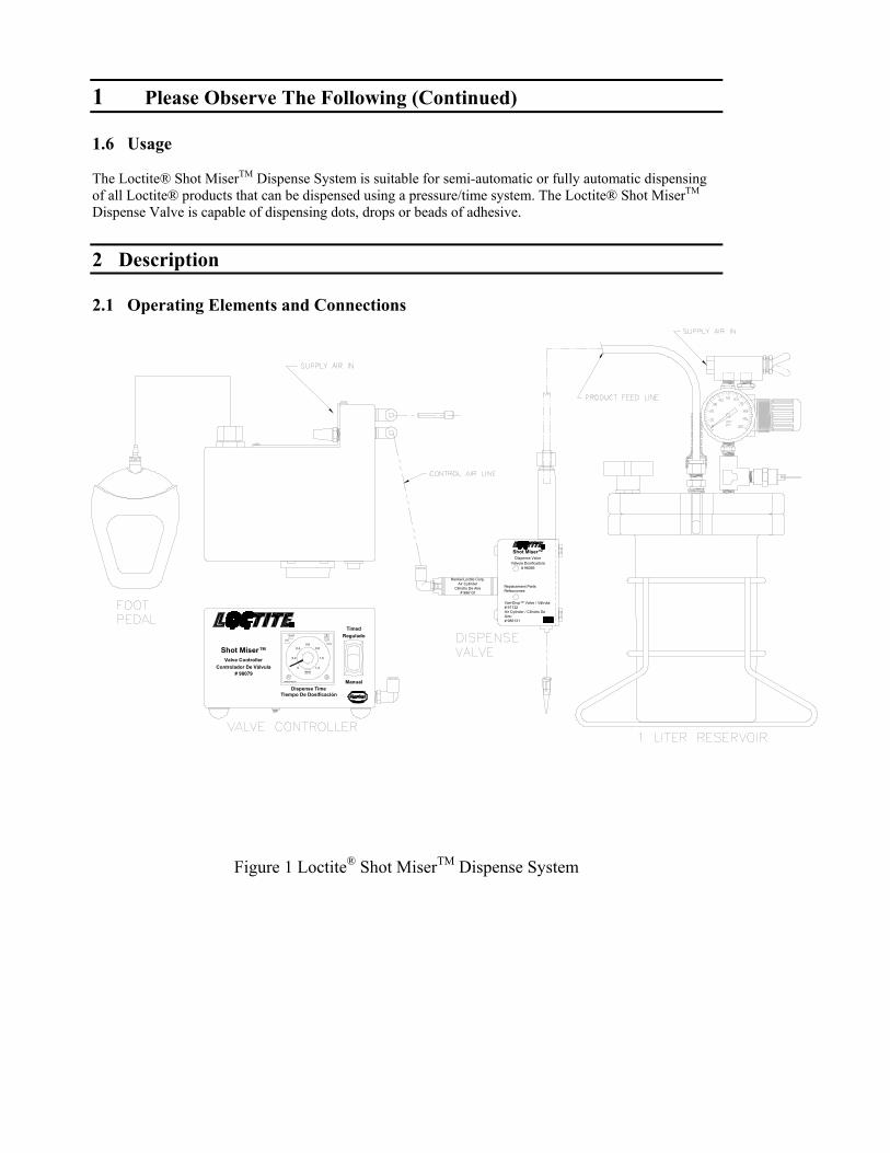
1.6 Usage
The Loctite® Shot MiserTM Dispense System is suitable for semi-automatic or fully automatic dispensingof all Loctite® products that can be dispensed using a pressure/time system. The Loctite® Shot MiserTM
Dispense Valve is capable of dispensing dots, drops or beads of adhesive. 2 Description
2.1 Operating Elements and Connections
Figure 1 Loctite® Shot MiserTM Dispense System
Henkel Loctite Corp.Air Cylinder
Cilindro De Aire# 986131
Shot Miser™Valve Controller
Controlador De Válvula# 98079
0.6
1.0
Dispense TimeTiempo De Dosificación
OMRON H3CR
0.4
0
0.2
min1.2
0.8
Manual
POWER
OUT
TimedReguladoA
MODE
Replacement Parts:Refacciones:
Vari-Drop™ Valve / Válvula:# 97132Air Cylinder / Cilindro De Aire:# 986131
Shot Miser™Dispense Valve
Válvula Dosificadora# 98085
2 Description (Continued)
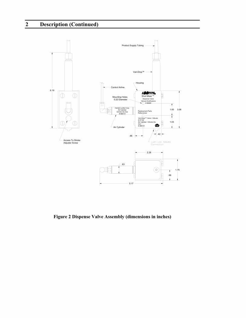
Figure 2 Dispense Valve Assembly (dimensions in inches)
™ Valve / Válvula:
# 986131Aire:Air Cylinder / Cilindro De # 97132Vari-Drop
# 986131Cilindro De Aire
Air CylinderHenkel Loctite Corp.
Válvula Dosificadora
Refacciones:Replacement Parts:
# 98085
Dispense ValveShot Miser
Access To StrokeAdjuster Screw
Air Cylinder
Housing
Control Airline
Vari-Drop™
Product Supply Tubing
.63
5.17
.66
2.28
.88
1.75
.42
1.03
6.19
Mounting Holes0.22 Diameter
1.00 3.06
TM

2 Description (Continued)
Figure 3 Reservoir Assembly
2 Description (Continued)
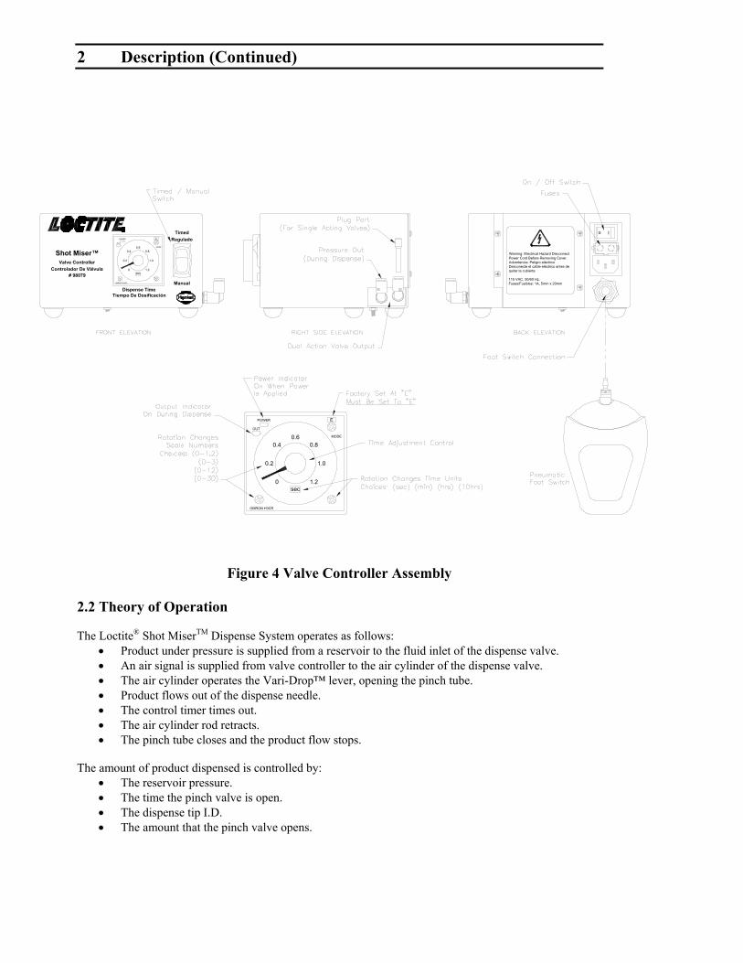
Figure 4 Valve Controller Assembly
2.2 Theory of Operation
The Loctite® Shot MiserTM Dispense System operates as follows:• Product under pressure is supplied from a reservoir to the fluid inlet of the dispense valve.• An air signal is supplied from valve controller to the air cylinder of the dispense valve.• The air cylinder operates the Vari-Drop™ lever, opening the pinch tube.• Product flows out of the dispense needle. • The control timer times out.• The air cylinder rod retracts.• The pinch tube closes and the product flow stops.
The amount of product dispensed is controlled by:• The reservoir pressure.• The time the pinch valve is open.• The dispense tip I.D.• The amount that the pinch valve opens.
Dispense TimeTiempo De Dosificación
Shot Miser™Valve Controller
Controlador De Válvula# 98079
Manual
ReguladoTimed
Warning: Electrical Hazard Disconnect Power Cord Before Removing Cover.Advertencia: Peligro eléctrico Desconecte el cable eléctrico antes de quitar la cubierta.
115 VAC, 50/60 Hz.Fuses/Fusibles: 1A, 5mm x 20mm
OMRON H3CR
0.6
sec
0.4
0
0.2
OUT
POWER
0.8
1.2
1.0
o I
MODE
E
OMRON H3CR
0sec
1.2
POWER
0.4
0.2
OUT
E
1.0
0.80.6 MODE
3 Technical Data
Loctite Shot® MiserTM Dispense Valve 98085
Pneumatic Supply min. 30 psig, max. 70 psig
Quality filtered to 10 µm, oil free, non-condensing
Control Air Connection 4mm (.157”)
Compressed Air Usage less than 1 scfm per stroke.
Product Pressure 0 psig to 80 psig
Product feed line 6.3 mm (.250)
Weight (less tubing & dispense needle) 228 grams (0.5 lbs.)
Loctite® Shot MiserTM Valve Controller 98079
Input Voltage / Cycles 115VAC, 50/60 HzFuse 1 Amp, 250V, 5mm X 20mm, Fast Acting Size (width x depth x height) 6.1 inches x 6.9 inches x 3.9 inchesWeight 3.5 pounds
Loctite® 1 Liter Shot MiserTM Reservoir 98090
Pneumatic Supply 100 PSI maximumSize (width x depth x height) 8.5 inches x 8.5 inches x 13.25 inchesWeight 8.5 pounds
4 Installation
Caution!DO NOT REMOVE ANY ITEMS THAT ARE SEALED IN PLASTIC BAGS UNTILTHEY ARE TO BE USED AS THEY MAY BECOME CONTAMINATEDRESULTING IN PERFORMANCE PROBLEMS.
4.1 Mounting
Secure Loctite® Shot MiserTM Dispense Valve (Part no. 98085) to a mounting surface with #10 dia. or 5mm dia. screws. The hole pattern is given in Figure 2. Tighten the mounting screws to approximately 10-inch pound torque.
Loctite® 1 Liter Shot MiserTM Reservoir 98090
Notice • Always use wire stand to support the reservoir.• Never pour product directly into the reservoir

4 Installation (Continued)
4.2 Connecting Air Line / Reference – Figure 1
Loctite® Shot MiserTM Dispense System
• Connect foot pedal, as shown in Figure 1, to the valve controller.• Connect 4mm airline from the normally not passing port, first the air line connection from
front of controller, then to the air cylinder on the dispense valve.• Insure that normally passing port has port plug installed (second airline connection from front
of controller).• Connect supply air to ‘Air In Port’ on valve controller.• Connect supply air to ‘Air In Port’ on reservoir.
4.3 Product Supply Tube
Note that this is a Teflon® lined tube. Slide the nut and ferrule onto the product supply tube. Push the end of the product supply tube into the Vari-Drop™. Make sure the end of the product
supply tube bottoms in the Vari-Drop™. Position the nut and ferrule and tighten the fitting nut 1 to 1½ turns past finger tight. Connect the other end of the product supply tube to the product pressure reservoir as stated in
‘Install Anti-Bubbler’.
4.4 Installing the Anti–Bubbler to .5 liter and 2 liter Reservoirs
Anti-Bubbler
The anti-bubbler is inserted at the end of the product supply tube that resides in the product reservoir. Thepurpose of the anti-bubbler is to minimize the amount of adhesive that will run out of the product supplytube when the reservoir lid is removed to re-fill the product reservoir.
A. Anti-Bubbler Installation – ¼ inch tubing
Install the spring guard, the fitting nut, and the ferrule onto the feed line. Insert feed line into the fittinglocated in the reservoir lid. Insert the anti – bubbler into anti-bubbler connection sleeve. Push anti-bubblerconnection sleeve onto 1/4 inch feed line. Position the feed line so that the anti-bubbler is close to thebottom of the adhesive bottle.
A d a p te rC o n n e c tio n S le e v e
F e e d lin e to V a lv e

4 Installation (Continued)
B. Anti-Bubbler Installation –3/8 inch tubing
Install the spring guard, the fitting nut, and the ferrule onto the feed line. Insert the feed line into fittinglocated in the reservoir lid. Insert the anti-bubbler into 3/8 inch feed line. Position feed line so that the anti-bubbler is close to the bottom of the adhesive bottle.
Adapter
Feedline to Valve
4.5 Dispense Tip
Position a suitable dispense needle in the Luer-Lok adapter and tighten securely.
5 Operations
5.1 Priming the Valve
Connect the utilities. Place a full product bottle in the reservoir. Set the reservoir pressure to a value suitable to the product viscosity (low pressure for low
viscosity product, higher pressure for high viscosity product). Position a container under the dispense nozzle. If it is not possible to position the container under
the dispense nozzle, use the silicone tube to route the outlet point to a container in a remotelocation.
Set valve controller on “Manual” control to open the valve. On the reservoir set pressure/vent control (toggle switch) to pressure positon. Open the valve until air free product flows at the dispense point. Remove the container or tube. The valve is ready to dispense. Once the valve has been primed, set valve controller to ‘Timed Mode’
5.2 Adjusting the amount of Loctite Product dispensed
The Loctite® Shot Miser Valve™ is part of a pressure-time dispense system.Here are the variables that control the amount of product dispensed:
Product pressure.Higher pressure = more product flowLower pressure = less product flow
Time the valve is openLonger time = more product flowShorter time = less product flow
Needle sizeLarger needle inside diameter = more product flowSmaller needle inside diameter = less product flow
5 Operations (Continued)
Stroke adjuster setting.More valve opening = more product flowLess valve opening = less product flow
Generally speaking the stroke adjuster setting is the least useful of the above (4) variables. This is becauseit has no numerical set point. Pressure, time and needle size all have numerical values that can be recordedand repeated.
Because of the large number of products only general guidelines will be given for dispensing. Higherviscosity products will require higher pressures, longer times and larger needle I.D. The reverse is true forlower viscosity products.
6 Maintenance and Cleaning
6.1 Cleaning
The product dispensing section of the Loctite® Vari-Drop™ can be flushed with Loctite® EquipmentFlushing Solvent supplied from a suitable reservoir. Adjust the reservoir pressure to a low value to reducethe flow rate.
6.2 Maintenance
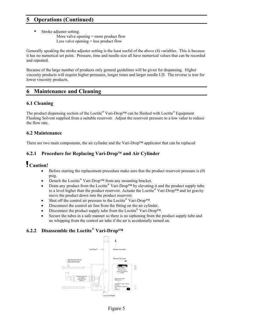
There are two main components, the air cylinder and the Vari-Drop™ applicator that can be replaced
6.2.1 Procedure for Replacing Vari-Drop and Air Cylinder
Caution!• Before starting the replacement procedure make sure that the product reservoir pressure is (0)
psig. • Detach the Loctite® Vari-Drop™ from any mounting bracket.• Drain any product from the Loctite® Vari-Drop™ by elevating it and the product supply tube
to a level higher than the product reservoir. Actuate the Loctite® Vari-Drop™ and let gravitymove the product down into the product reservoir.
• Shut off the control air pressure to the Loctite® Vari-Drop™.• Disconnect the control air line from the fitting on the air cylinder.• Disconnect the product supply tube from the Loctite® Vari-Drop™.• Secure the tubes in a safe manner so there is no siphoning from the product supply tube and
no whipping from the control air tube if the air is accidentally turned on.
6.2.2 Disassemble the Loctite® Vari-Drop™
Shot Miser ™
Válvula Dosificadora# 98085
Dispense Valve
Refacciones:Replacement Parts:
™ Valve / Válvula:
Air Cylinder / Cilindro De
Vari-Drop# 97132
Aire:# 986131
Henkel Loctite Corp.
# 986131Cilindro De Aire
Air Cylinder
Remove the CoverRemove the #10-32Nuts and Screws
Vari-Drop™ Remove the Valve
Luer-Lok Adapter
Figure 5

6 Maintenance and Cleaning (Continued)
6.2.3 Reassembling the Loctite® Vari-Drop™
Figure 6
• Connect the product supply tube to the Loctite® Vari-Drop™.• Connect the control air line to the fitting on the air cylinder.• Attach the Loctite® Vari-Drop™ to the mounting bracket.• Prime the Loctite® Vari-Drop™ per the instructions on pg. 8 of this manual.• The Loctite® Vari-Drop™ is now ready for operation.
Henkel Loctite Corp.Air Cylinder
Cilindro De Aire# 986131
Henkel Loctite Corp.Air Cylinder
Cilindro De Aire# 986131
Depress The Vari-Drop™ Lever ToHorizontal Then Slide The Vari-Drop™Down Into The Clamp.
.100
Then Slide The Vari-Drop™ Forward Into The Clamp So That The Luer-Lok Adapter Is At The Specified Dimension Beyond The Clamp.
Apply Lithum Grease ToVari-Drop™ Lever
Dispense Valve
# 97132Air Cylinder / Cilindro De
# 986131Aire:
™ Valve / Válvula:
Válvula Dosificadora
Refacciones:Replacement Parts:
# 98085
In Clamp & CoverPosition #10-32 Screws
Vari-Drop™ Position Cover Over The™ & Clamp
™Shot Miser
Vari-Drop

7 Troubleshooting
Type of Malfunction Possible Cause CorrectionLoctite® Vari-Drop™ does notdispense product and the StrokeAdjuster does not move when theunit is cycled.
No pressure in product reservoir.
Valve controller is not functioning.
Mode setting on timer is incorrect.
No air supply.Low air pressure.Stroke Adjuster set to zero stroke.Air cylinder defective.Control valve faulty.
Switch pressure/vent control topressure position.Check that is plugged in to 120 voltreceptacle.Set timer mode, located on front face oftimer, to “E’ mode.Turn on air supply.Adjust air pressure to at least 60 psig.Reset Stroke Adjuster.Replace air cylinder.Replace control valve.
Unit does not dispense productbut the Stroke Adjuster movesnormally when the unit is cycled.
Control logic problem.No or low reservoir pressure.Product reservoir is empty.Unit is not primed.
Cured product in product tubing orfittings.Cured product in dispense needle.Vari-Drop™ lever failure.
Check program & componentsIncrease reservoir pressure.Refill reservoir.Re-prime the unit and check producttubing and product tube fittings forleaks.Replace tubing or fittings.
Replace needle.Replace Vari-Drop™.
Product leaks from dispenser. Vari-Drop™ pinch tube failure.Reservoir Pressure To High.
Replace or repair Vari-Drop™ .Reduce Reservoir Pressure.

8 Spare Parts and Accessories
The following is a list of recommended parts or assemblies that may be required to repairthe Loctite® Shot MiserTM Dispense System.
8.1 Spare Parts
Loctite® Shot MiserTM Dispense Valve 98085
Description Loctite Part No.Air Cylinder 986131Loctite® Vari-Drop™ 97132Loctite® Vari-Drop™ Repair Kit 97249Nut and Sleeve for Product Tubing 993247Grease, silicone, 6 gr. tube 997569
Loctite® Shot MiserTM Valve Controller 98079
Description Loctite Part No.Foot Pedal with fitting and Tubing 98126Air Actuated Remote Electrical Switch 986262Solenoid Valve, 4 Way 986264
Loctite® 1 Liter Shot MiserTM Reservoir 98090
Description Loctite Part No.Pressure Relief Valve 9926413 Way Toggle Valve 98094Pressure Regulator 98129Anti-Bubbler Kit 2 adapters & 2 sleeves 984687O-Ring , standard for lid 997312O-Ring for use with acetone based primers 983055Pressure Gauge 98130Tank Fitting, 3/8” Product Feedtube 9987213/8” Product Feedtube 979701/4” Product Feedtube 97972

8 Spare Parts and Accessories (continued)
8.2 Accessories
Description Loctite Part No. Qty.Needle Kit 97262 1Dispense Tips, Stainless Steel - StraightDispense Tip, Luer-Lok, 15 gauge 97225 Box of 50Dispense Tip, Luer-Lok, 18 gauge 97226 Box of 50Dispense Tip, Luer-Lok, 20 gauge 97227 Box of 50Dispense Tip, Luer-Lok, 25 gauge 97228 Box of 50Dispense Tips, FlexibleDispense Tip, Luer-Lok, 15 gauge 97229 Box of 50Dispense Tip, Luer-Lok, 18 gauge 97230 Box of 50Dispense Tip, Luer-Lok, 20 gauge 97231 Box of 50Dispense Tip, Luer-Lok, 25 gauge 97232 Box of 50Dispense Tips, Taper TipDispense Tip, Luer-Lok, 16 gauge 97221 Box of 50Dispense Tip, Luer-Lok, 18 gauge 97222 Box of 50Dispense Tip, Luer-Lok, 20 gauge 97223 Box of 50Dispense Tip, Luer-Lok, 22 gauge 97224 Box of 50Dispense Tip, Luer-Lok, 25 gauge PTFElined Stainless Steel Tip
97238 Box of 50
Dispense Tip, Luer-Lok, Plastic, 15 gauge 97261 Box of 50
9 Warranty
Henkel Loctite expressly warrants that all products referred to in this Instruction Manualunder Loctite® Shot Miser™ Dispense System 98116 (hereafter called "Products") shallbe free from defects in materials and workmanship. Liability for Henkel Loctite shall belimited, at its option, to replacing those Products which are shown to be defective eitherin materials or workmanship or to credit to the purchaser the amount of the purchaseprice thereof (plus freight and insurance charges paid therefor by the user). Thepurchaser's sole and exclusive remedy for breach of warranty shall be such replacementor credit.
A claim of defect in materials or workmanship in any Products shall be allowed onlywhen it is submitted to Henkel Loctite in writing within one month after discovery of thedefect or after the time the defect should have reasonably have been discovered and inany event, within twelve months after the delivery of the Products to the purchaser. Nosuch claim shall be allowed in respect of Products which have been neglected orimproperly stored, transported, handled, installed, connected, operated, used ormaintained or in the event of unauthorized modification of the Products including; whereproducts, parts or attachments for use in connection with the Products are available fromHenkel Loctite, the use of products, parts or attachments which are not manufactured byHenkel Loctite.
No Products shall be returned to Henkel Loctite for any reason without prior writtenapproval from Henkel Loctite. Products shall be returned freight prepaid, in accordancewith instructions from Henkel Loctite.
NO WARRANTY IS EXTENDED TO ANY EQUIPMENT THAT HAS BEEN ALTERED; MISUSED,NEGLECTED, OR DAMAGED BY ACCIDENT, OR IF THE SYSTEM IS USED TO DISPENSE ANYLIQUID MATERIAL OTHER THAN LOCTITE® PRODUCTS.
EXCEPT FOR THE EXPRESS WARRANTY CONTAINED IN THIS SECTION, HENKEL LOCTITEMAKES NO WARRANTY OF ANY KIND WHATSOEVER, EXPRESS OR IMPLIED, WITHRESPECT TO THE PRODUCTS.
ALL WARRANTIES OR MERCHANTABILITY, FITNESS FOR A PARTICULAR PURPOSE, ANDOTHER WARRANTIES OF WHATEVER KIND (INCLUDING AGAINST PATENT ORTRADEMARK INFRINGEMENT) ARE HEREBY DISCLAIMED BY HENKEL LOCTITE ANDWAIVED BY THE PURCHASER.
THIS SECTION SETS FORTH EXCLUSIVELY ALL OF LIABILITY FOR HENKEL LOCTITE TOTHE PURCHASER IN CONTRACT, IN TORT OR OTHERWISE IN THE EVENT OF DEFECTIVEPRODUCTS.
WITHOUT LIMITATION OF THE FOREGOING, TO THE FULLEST EXTENT POSSIBLE UNDERAPPLICABLE LAWS, HENKEL LOCTITE EXPRESSLY DISCLAIMS ANY LIABILITYWHATSOEVER FOR ANY DAMAGES INCURRED DIRECTLY OR INDIRECTLY INCONNECTION WITH THE SALE OF USE OF, OR OTHERWISE IN CONNECTION WITH, THEPRODUCTS, INCLUDING, WITHOUT LIMITATION, LOSS OF PROFITS AND SPECIAL,INDIRECT OR CONSEQUENTIAL DAMAGES, WHETHER CAUSED BY NEGLIGENCE FROMHENKEL LOCTITE OR OTHERWISE.
-END-

EQUIPMENTEQUIPOOperation ManualManual de Operación
Loctite Shot Miser™ Dispense SystemEquip Dosificador Shot Miser™Part Number / Numero de Parte 98116
0.2
OMRON H3CR
OUT
POWER Regulado
0min
1.2
0.40.6
0.8
1.0
MODE
Manual
A
Timed
Shot Miser™Valve Controller
Controlador De Válvula# 98079
Dispense TimeTiempo De Dosificación
Shot Miser™Dispense Valve
Válvula Dosificadora# 98085
Henkel Loctite Corp.Air Cylinder
Cilindro De Aire# 986131
Vari-Drop™ Valve / Válvula:# 97132Air Cylinder / Cilindro De Aire:# 986131
Replacement Parts:Refacciones:

Contenido
1. POR FAVOR OBSERVE LO SIGUIENTE_______________________________ 201.1 SECCIONES IMPORTANTES _______________________________________________________201.2 PARA SU SEGURIDAD ___________________________________________________________201.3 DESEMPAQUE E INSPECCIÓN______________________________________________________211.4 PARTES SUMINISTRADAS_______________________________________________________211.5 CARACTERÍSTICAS _____________________________________________________________211.6 USO ________________________________________________________________________22
2. DESCRIPCIÓN_____________________________________________________ 222.1 ELEMENTOS DE OPERACIÓN Y CONTROLES ________________________________________222.2 TEORÍA DE OPERACIÓN _________________________________________________________25
3. DATOS TÉCNICOS_________________________________________________ 26
4. INSTALACIÓN ____________________________________________________ 264.1 MONTAJE ____________________________________________________________________264.2 CONECTANDO LA LÍNEA DE AIRE / REFERENCIA – FIGURA 1______________________________274.3 TUBO DE SUMINISTRO DE PRODUCTO ______________________________________________274.4 INSTALACIÓN DEL ANTI-BURBUJAS EN ENVASES DE 0.5 Y 2 LITROS ________________________274.5 PUNTA DE DOSIFICACIÓN______________________________________________________28
5. OPERACIONES ____________________________________________________ 285.1 PURGA DE LA VÁLVULA _________________________________________________________285.2 AJUSTANDO LA CANTIDAD A DOSIFICAR_____________________________________________29
6. LIMPIEZA Y MANTENIMIENTO _____________________________________ 296.1 LIMPIEZA ____________________________________________________________________296.2 MANTENIMIENTO ______________________________________________________________306.2.1 Procedimiento de Reemplazo de Loctite® Vari-Drop™ _________________________________ 306.2.2 Desensamblando el Loctite® Vari-Drop™ ___________________________________________ 306.2.3 Ensamblando el Loctite® Vari-Drop™ ______________________________________________ 31
7. SOLUCIÓN DE FALLAS ____________________________________________ 32
8. REFACCIONES Y ACCESORIOS _____________________________________ 338.1 REFACCIONES_________________________________________________________________338.2 ACCESORIOS__________________________________________________________________34
9 GARANTÍA ___________________________________ PORTADA POSTERIOIR

1. Por Favor Observe lo Siguiente
1.1 Secciones importantes Advertencia!
Se refiere a medidas y regulaciones de seguridad que protegen al operador o aotras personas
Precaución!Enfatiza sobre lo que debe ser hecho o evitar para que la unidad o el propietariono sufran daño
Nota:Da recomendaciones para el mejor manejo de la unidad durante la operación oactividades de servicio.
1.2 Para su Seguridad Advertencia!
• Observe todas las advertencias. Lea y entienda todas las instrucciones en elmanual antes de instalar u operar el equipo.
• Este equipo ha sido diseñado y probado para ser usado con productosLoctite® tanto para tiempo y presión. Los productos pueden tener unaviscosidad de hasta 80,000 centiopoise.
• No use el equipo para otro fin mas que para el señalado• Asegúrese que los adhesivos, solventes o fluidos usados son compatibles
químicamente con las partes húmedas• Siempre verifique y lea las hojas de datos de seguridad de los materiales
antes de usar cualquier adhesivo, solvente u otro químico en este equipo.Cumpla con todas las advertencias e instrucciones de seguridad.
• Siempre use protección de ojos, guantes, ropa y respirador tal como serecomienda en este manual o en la hoja de seguridad del material.
• Cualquier uso inadecuado de este equipo o accesorios como una sobrepresión, partes modificadas, uso de químicos incompatibles, adhesivos osolventes, partes dañadas o no recomendadas, pueden causar ruptura y fugas,salpicaduras en los ojos o piel o cualquier otro daño personal.
• Nunca altere o modifique las partes del equipo. Hacerlo puede ocasionarmala funcionalidad
• Verifique el equipo regularmente y repare o reemplace las partes dañadas deinmediato.
• Nunca exceda la presión de trabajo recomendada o la presión máxima deentrada estipulada en el equipo o en el manual.
• Aterrice apropiadamente las conexiones eléctricas como lo recomienda estemanual o la hoja de datos de seguridad.
• Siempre mantenga las manos y dedos lejos de las partes móviles para evitarriesgo de daño.
• Siempre libere la presión y apague el equipo cuando haga revisiones deservicio.
• Mantenga este manual para futuras referencias.
1. Por Favor Observe lo Siguiente (continua)
1.3 Desempaque e InspecciónDesempaque cuidadosamente los componentes del sistema y examine losartículos suministrados en la caja. Verifique las partes de cualquier daño que pudohaber sufrido durante el transporte. Si existe daño notifique al transportistainmediatamente. Las reclamaciones deben ser a través del transportista y debenser notificadas al proveedor.
1.4 Artículos Suministrados
Válvula Dosificadora Loctite® Shot Miser™ 98085Selector de agujasTubo de producto / 7 piesLínea de control de aire / 6 piesManual de operaciónManual de operación del Vari-drop™
Controlador de Válvula Loctite® Shot Miser™ 98079PedalManguera de pedal / 10 piesCable de energíaManual de operación
Tanque de 1 litro Loctite® Shot Miser™ 98090Adaptador anti burbujasConector anti-burbujasResorte de protecciónTubo de suministro de producto / 6 piesManual de operación
1.5 Características
Válvula dosificadora Loctite® “Shot Miser™” 98085• Usado en aplicaciones semi automáticas o procesos completamente
automatizados• Tanques adaptables al tamaño de la presentación del producto• Dosifica productos Loctite de hasta 80,000 cP• Permite repitibilidad en la dosificación desde gotas hasta cordones.
Controlador de válvula Loctite® “Shot Miser™” 98079• Cronometro análogo de fácil lectura• Modo continuo o cronometrado de 0.10 segundos a horas• Salida neumática para válvulas de una o doble acción• Pedal neumático
Tanque de 1 litro Loctite® “Shot Miser™” 98090• Presión de 0 a 100 psi• Capacidad del recipiente: botella 1 lb, 500 gr, 250 ml.
1 Por Favor Observe lo Siguiente (continua)
1.6 Uso
El equipo dosificador Loctite® Shot Miser™ es apropiado para una dosificaciónsemi o completamente automatizada de todos los productos Loctite® que puedenser controlados con presión y tiempo. Este puede dosificar puntos, gotas ocordones de adhesivo.
2. Descripción
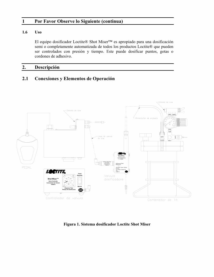
2.1 Conexiones y Elementos de Operación
Figura 1. Sistema dosificador Loctite Shot Miser
Shot Miser™Dispense Valve
Válvula Dosificadora# 98085
Henkel Loctite Corp.Air Cylinder
Cilindro De Aire# 986131
Vari-Drop™ Valve / Válvula:# 97132Air Cylinder / Cilindro De Aire:# 986131
Replacement Parts:Refacciones:
Shot Miser™Valve Controller
Controlador De Válvula# 98079
Dispense TimeTiempo De Dosificación
0.2
OMRON H3CR
OUT
POWER Regulado
0min
1.2
0.40.6
0.8
1.0
MODE
Manual
A
Timed

2. Descripción (continua)
Figura 2. Ensamble de Válvula Dosificadora (dimensiones en pulgadas)
0.22" DiameterVálvula Dosificadora
Tornillo de ajusteAcceso a regulador
5.17"
3.06"
1.75"
Conexion Luer Lok
.63"
.88"
2.28"
Replacement Parts:Refacciones:
Vari-Drop
Air Cylinder / Cilindro De
# 986131Cilindro de aire
.66"
Aire:
Henkel Loctite Corp.
Cilindro De Aire# 986131
Air Cylinder
# 971321.03"
.42"
™ Valve / Válvula:
# 98085
1.00"
Agujeros de montaje
Tubo de alimentacion de producto
Linea de control de aire6.19"
Alojamiento
Shot MiserDispense Valve
Vari-Drop™
™
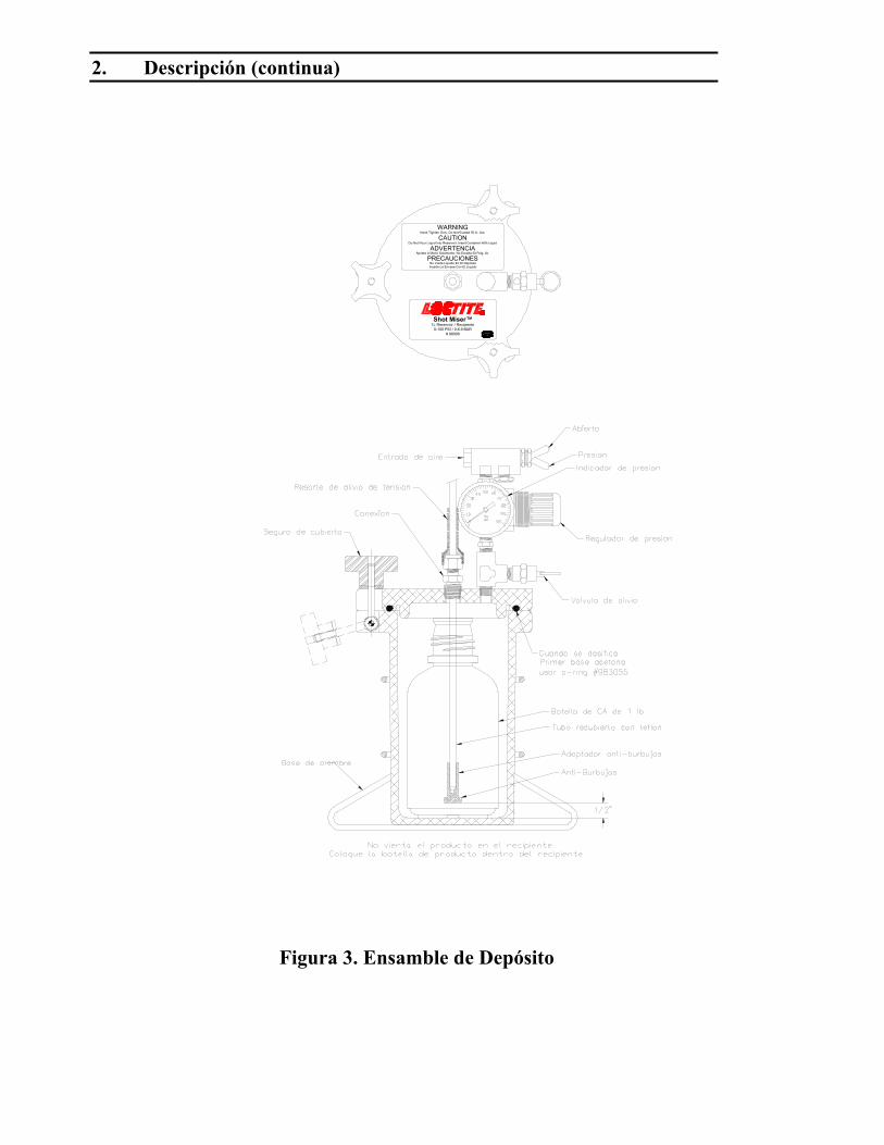
2. Descripción (continua)
Figura 3. Ensamble de Depósito
Shot Miser™
No Vierta Líquido En El DepósitoInserte Le Envase Con El Líquido
0-100 PSI / 0-6.9 BAR# 98090
1L Reservoir / Recipiente
WARNINGCAUTION
PRECAUCIONESADVERTENCIA
Hand Tighten Only, Do Not Exceed 50 In. Lbs.
Apriete A Mano Solamente, No Exceda 50 Pulg. Lb.
Do Not Pour Liquid Into Reservoir, Insert Container With Liquid

2 Descripción (continua)
Figura 4. Ensamble de controlador de válvula.
2.2 Teoría de Operación
El dosificador Loctite® Shot Miser™ opera de la siguiente manera:• El producto presurizado fluye del recipiente hacia la entrada de la válvula
dosificadora• Se envía una señal de aire del controlador de la válvula al cilindro de la
válvula dosificadora• El cilindro activa el Vari-Drop™• El producto comienza a fluir• El cronometro termina su ciclo• El cilindro se retrae• El Vari-Drop™ ya no se acciona y deja de fluir el producto.
La cantidad de producto dosificado es controlado por:• La presión del tanque• Tiempo que el Vari-Drop™ es accionado• Diámetro interno de la aguja dosificadora• La fuerza con la que se activa el Vari-Drop™
OMRON H3CR
0sec
1.2
0.2
0.4
POWER
OUT
E
MODE0.6
1.0
0.8
TimedRegulado
Manual
Shot Miser™Valve Controller
Controlador De Válvula# 98079
Dispense TimeTiempo De Dosificación
OMRON H3CR
0.6
sec
0.4
0
0.2
OUT
POWER
0.8
1.2
1.0
MODE
E
Warning: Electrical Hazard Disconnect Power Cord Before Removing Cover.Advertencia: Peligro eléctrico Desconecte el cable eléctrico antes de quitar la cubierta.
115 VAC, 50/60 Hz.Fuses/Fusibles: 1A, 5mm x 20mm
Io
3. Datos Técnicos
Válvula dosificadora Loctite® Shot Miser™ 98085
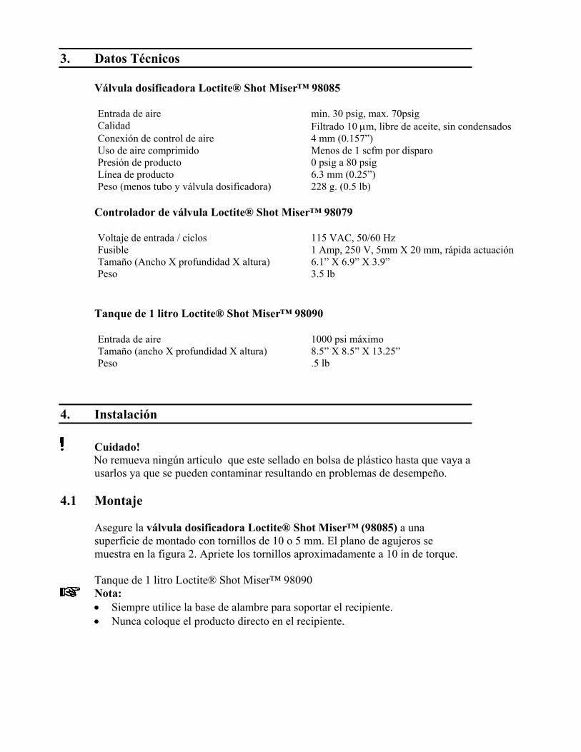
Entrada de aire min. 30 psig, max. 70psigCalidad Filtrado 10 µm, libre de aceite, sin condensadosConexión de control de aire 4 mm (0.157”)Uso de aire comprimido Menos de 1 scfm por disparoPresión de producto 0 psig a 80 psigLínea de producto 6.3 mm (0.25”)Peso (menos tubo y válvula dosificadora) 228 g. (0.5 lb)
Controlador de válvula Loctite® Shot Miser™ 98079
Voltaje de entrada / ciclos 115 VAC, 50/60 HzFusible 1 Amp, 250 V, 5mm X 20 mm, rápida actuación Tamaño (Ancho X profundidad X altura) 6.1” X 6.9” X 3.9”Peso 3.5 lb
Tanque de 1 litro Loctite® Shot Miser™ 98090
Entrada de aire 1000 psi máximoTamaño (ancho X profundidad X altura) 8.5” X 8.5” X 13.25”Peso .5 lb
4. Instalación
Cuidado!No remueva ningún articulo que este sellado en bolsa de plástico hasta que vaya ausarlos ya que se pueden contaminar resultando en problemas de desempeño.
4.1 Montaje
Asegure la válvula dosificadora Loctite® Shot Miser™ (98085) a unasuperficie de montado con tornillos de 10 o 5 mm. El plano de agujeros semuestra en la figura 2. Apriete los tornillos aproximadamente a 10 in de torque.
Tanque de 1 litro Loctite® Shot Miser™ 98090Nota: • Siempre utilice la base de alambre para soportar el recipiente.• Nunca coloque el producto directo en el recipiente.

4. Instalación (continua)
4.2 Conectando la Línea de Aire / Referencia – Figura 1
Sistema dosificador Loctite® Shot Miser™ • Conecte el pedal como se muestra en la figura 1, al controlador de la válvula.• Conecte la línea de aire de 4 mm del puerto normalmente cerrado, primero la
conexión de aire del controlador de enfrente, después al cilindro de aire de laválvula dosificadora.
• Asegúrese de que el puesto normalmente abierto tiene el conector (segundalínea de aire del frente del controlador).
• Conecte el aire al “Puesto de entrada de aire” del controlador de la válvula.• Conecte la entrada de aire del tanque en el “puesto de entrada de aire”.
4.3 Tubo de alimentación de Producto• Nótese que es un tubo recubierto con Teflón®.• Deslice la tuerca de sujeción por el tubo• Empuje el final de la línea de alimentación hacia el Vari-Drop™.
Asegurándose de que quede una conexión segura y sin fuga entre el Vari-Drop™ y el tubo de alimentación.
• Asegure la tuerca con la parte trasera del Vari-Drop™ dando de 1 a 1 1/2 • Conecte el otro extremo de la línea en el recipiente como lo indica la
“instalación del anti-burbujas”.
4.4 Instalación del Anti-Burbujas en Envases de 0.5 y 2 litros
Anti-BurbujasEl anti-burbujas debe ser insertado al final del tubo que queda dentro del envase.El propósito de este es minimizar la cantidad de adhesivo que saldrá por el tubode alimentación cuando este sea rellenado o cambiado.
A. Instalación con Tubo de ¼”Instale el resorte de guarda, la tuerca y el conector en el tubo de alimentación,inserte la línea en la tapa del recipiente, inserte el anti-burbujas en su adaptador.Empuje el anti-burbujas hacia la conexión de ¼”. Posicione la línea en el fondodel envase de adhesivo.
Tubo De Aliuentacion
ConectorAdaptador
4. Instalación (continua)
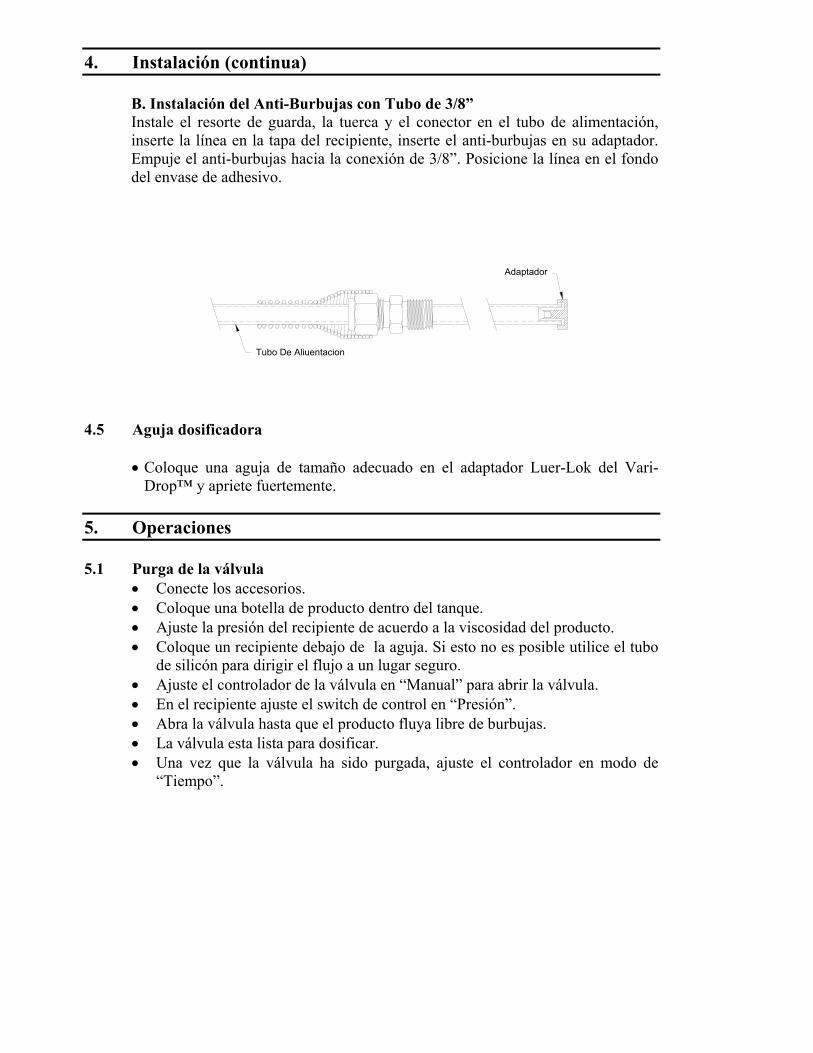
B. Instalación del Anti-Burbujas con Tubo de 3/8”Instale el resorte de guarda, la tuerca y el conector en el tubo de alimentación,inserte la línea en la tapa del recipiente, inserte el anti-burbujas en su adaptador.Empuje el anti-burbujas hacia la conexión de 3/8”. Posicione la línea en el fondodel envase de adhesivo.
Tubo De Aliuentacion
Adaptador
4.5 Aguja dosificadora
• Coloque una aguja de tamaño adecuado en el adaptador Luer-Lok del Vari-Drop™ y apriete fuertemente.
5. Operaciones
5.1 Purga de la válvula• Conecte los accesorios.• Coloque una botella de producto dentro del tanque.• Ajuste la presión del recipiente de acuerdo a la viscosidad del producto.• Coloque un recipiente debajo de la aguja. Si esto no es posible utilice el tubo
de silicón para dirigir el flujo a un lugar seguro.• Ajuste el controlador de la válvula en “Manual” para abrir la válvula.• En el recipiente ajuste el switch de control en “Presión”.• Abra la válvula hasta que el producto fluya libre de burbujas.• La válvula esta lista para dosificar.• Una vez que la válvula ha sido purgada, ajuste el controlador en modo de
“Tiempo”.

5. Operaciones (continua)
5.2 Ajustando la Cantidad a DosificarEste sistema es manejado por tiempo y presión. Estas son las variables quecontrolan la cantidad a dosificar.• Presión del producto
Mayor presión = mas flujoMenor presión = menos flujo
• Tiempo que la válvula permanece abiertaMayor tiempo = mas flujoMenor tiempo = menos flujo
• Tamaño de la agujaMayor diámetro de aguja = mas flujoMenor diámetro = menos flujo
• Carrera del cilindroMas apertura de válvula = mas flujoMenos apertura de válvula = menos flujo
Generalmente el ajuste de la carrera del cilindro es el menos usado de lasvariables (4) esto es debido no tiene un punto de ajuste numérico. La presión ytiempo y el tamaño de la guja si tienen valores numéricos que pueden sergrabados y repetidos.
Debido a la gran cantidad de productos, se dan guías básicas para la dosificación.
6. Limpieza y Mantenimiento
6.1 LimpiezaLa sección de dosificación del Loctite® Vari-Drop™ puede ser limpiada con elsolvente limpiador Loctite® “Flushing solvent” coloque el recipiente dentro deltanque y purgue normalmente.

6 Limpieza y Mantenimiento (continua)
6.2 MantenimientoExisten dos componentes principales, el cilindro de aire y el Vari Drop™ quepueden ser reemplazados.
6.2.1 Procedimiento de Reemplazo de Vari-Drop™Cuidado!• Antes de iniciar el reemplazo asegúrese de que no hay presión en el
tanque.• Separe el Vari-Drop™ de cualquier soporte de montaje.• Drene todo el producto levantando el Vari-Drop™ mas alto que el
tanque, active el Vari-Drop™ y deje que el producto caiga porgravedad al recipiente.
• Corte la corriente de aire.• Desconecte la línea de control de aire del cilindro.• Desconecte la línea de producto del Vari-Drop™.• Asegure los tubos de manera que no haya goteo o soltura de los tubos
si se llegara a conectar el aire accidentalmente.
6.2.2 Desensamblando el Loctite® Vari-Drop™
Figura 5
Henkel Loctite Corp.Air Cylinder
Cilindro De Aire# 986131
y tornillos #10-32Remueve las tuercas
Dispense Valve
Adaptador Luer-Lok
# 97132Air Cylinder / Cilindro De
# 986131Aire:
™ Valve / Válvula:
Replacement Parts:Refacciones:
# 98085Válvula Dosificadora
Vari-Drop
™Vari-Drop
Remueve la cubierta
Shot Miser ™
Remueve la valvula

6 Limpieza y Mantenimiento (continua)
6.2.3 Ensamble de Loctite® Vari-Drop™
Figura 6.
• Conecte la entrada de aire al Loctite® Vari-Drop™.• Conecte la línea de control de aire al cilindro.• Monte el Loctite® Vari-Drop en el soporte.• Purgue el Loctite® Vari-Drop como se indica en la pagina 8.• El Loctite® Vari-Drop esta listo para operarse.
Válvula Dosificadora
# 986131Cilindro De Aire
Air CylinderHenkel Loctite Corp.
y coloquelo en el soporteOprima el gatillo del Vari-Drop™
Replacement Parts:
™ Valve / Válvula:
Air Cylinder / Cilindro De
ontener las dimensiones adecuadasColoque el Luer-Lok en la base para
Cilindro De Aire# 986131
Air CylinderHenkel Loctite Corp.
.100"# 986131Aire:
Refacciones:
# 97132
# 98085
Posicione los tornillos enla base y cubierta
Apply Lithum Grease ToVari-Drop™ Lever
sobre el Vari-Drop
Shot Miser
Coloque la cibierta
Dispense Valve
Vari-Drop™
™
™

7. Solucionando Fallas
Tipo de falla Causa posible CorrecciónEl Vari-Drop™ nodosifica y el golpe delcilindro no se activacuando comienza el ciclo.
- No hay presión en el tanque.
- No funciona el controlador.- El modo del controlador es
incorrecto.- No hay suministro de aire.- Baja presión de aire.
- El golpe del pistón esta ajustadoa cero.
- El cilindro de aire estadefectuoso.
- Falla en la válvula de control.
• Cambie el switch de control depresión en “presión”.
• Verifique la entrada de corriente.• Ajuste el controlador al modo “E”.
• Conecte suministro de aire.• Ajuste la presión por lo menos a
60psig.• Reinicie el cilindro.
• Reemplace el cilindro.
• Reemplace la válvula de control.
La unidad no dosificapero el cilindro hace suciclo normal.
- Problema de control lógico.
- Baja o nula presión en el tanque.- Tanque vació.- La unidad no esta purgada.
- Producto curado en el tubo oconexiones.
- Producto curado en la aguja.- Falla de Vari-Drop™.
• Cheque el programa y suscomponentes.
• Incremente la presión del tanque.• Rellene el tanque.• Purgue nuevamente y cheque todas
las conexiones.• Reemplace tubería o conexiones.
• Reemplace la aguja.• Reemplace el Vari-Drop™.
Existen fugas en elsistema.
- Falla en Vari-Drop™.
- La presión del tanque es muyalta.
• Reemplace o repare el Vari-Drop™.
• Reduzca la presión del Vari-Drop™.
8. Refacciones y Accesorios
A continuación se lista una serie de accesorios y partes que pueden ser requeridaspara el buen funcionamiento del equipo:
8.1 Refacciones
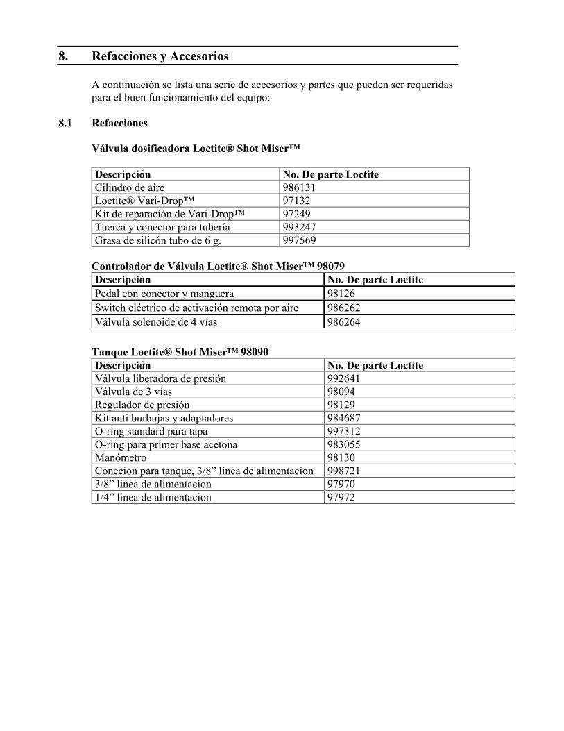
Válvula dosificadora Loctite® Shot Miser™
Descripción No. De parte LoctiteCilindro de aire 986131Loctite® Vari-Drop™ 97132Kit de reparación de Vari-Drop™ 97249Tuerca y conector para tubería 993247Grasa de silicón tubo de 6 g. 997569
Controlador de Válvula Loctite® Shot Miser™ 98079Descripción No. De parte LoctitePedal con conector y manguera 98126Switch eléctrico de activación remota por aire 986262Válvula solenoide de 4 vías 986264
Tanque Loctite® Shot Miser™ 98090Descripción No. De parte LoctiteVálvula liberadora de presión 992641Válvula de 3 vías 98094Regulador de presión 98129Kit anti burbujas y adaptadores 984687O-ring standard para tapa 997312O-ring para primer base acetona 983055Manómetro 98130Conecion para tanque, 3/8” linea de alimentacion 9987213/8” linea de alimentacion 979701/4” linea de alimentacion 97972
8. Refacciones y Accesorios (continua)
8.2 Accesorios
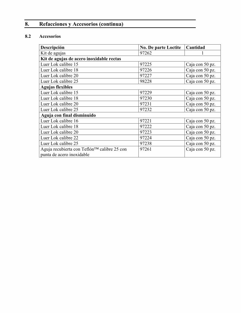
Descripción No. De parte Loctite CantidadKit de agujas 97262 1Kit de agujas de acero inoxidable rectasLuer Lok calibre 15 97225 Caja con 50 pz.Luer Lok calibre 18 97226 Caja con 50 pz.Luer Lok calibre 20 97227 Caja con 50 pz.Luer Lok calibre 25 98228 Caja con 50 pz.Agujas flexiblesLuer Lok calibre 15 97229 Caja con 50 pz.Luer Lok calibre 18 97230 Caja con 50 pz.Luer Lok calibre 20 97231 Caja con 50 pz.Luer Lok calibre 25 97232 Caja con 50 pz.Aguja con final disminuidoLuer Lok calibre 16 97221 Caja con 50 pz.Luer Lok calibre 18 97222 Caja con 50 pz.Luer Lok calibre 20 97223 Caja con 50 pz.Luer Lok calibre 22 97224 Caja con 50 pz.Luer Lok calibre 25 97238 Caja con 50 pz.Aguja recubierta con Teflón™ calibre 25 conpunta de acero inoxidable
97261 Caja con 50 pz.

9 Garantía
Henkel Loctite expresamente garantiza que todos los productos a los que se refiere este Manual deinstrucciones bajo Equipo dosificador Loctite® Shot Miser™ 98116 (en lo sucesivo llamado“Productos”) deberán estar libres de defectos en cuanto a materiales y mano de obra. Laresponsabilidad de Henkel Loctite deberá ser limitada, a su opción, para reemplazar aquellos productosque muestren estar defectuosos ya sea en cuanto a materiales o mano de obra o bien de acreditar alcomprador la cantidad del precio de compra y por lo tanto (más gastos de transporte y gastos deseguro pagados por lo tanto por el usuario). El único y exclusivo remedio por incumplimiento de lagarantía deberá ser el reemplazo o el crédito.
Se acepta una reclamación por defecto en los materiales o mano de obra en cualquiera de los Productossólo cuando sea dicho reclamo sea enviado por escrito a Henkel Loctite dentro del mes siguiente apartir del descubrimiento del defecto o después de un tiempo razonable en el que el defecto ha sidodescubierto en cualquier caso, dentro de doce meses a partir de la entrega de los Productos alcomprador. No se acepta un reclamo con respecto a los Productos que han sido descuidados,almacenados, transportados, manipulados, instalados, conectados, operados, usados o mantenidosinadecuadamente o en el caso de una modificación no autorizada de los Productos incluyendo dondelos productos, partes o accesorios para uso en conexión con los Productos están disponibles de HenkelLoctite, y se utilicen productos, partes o accesorios no fabricados por Henkel Loctite.
Ningún Producto deberá ser devuelto a Henkel Loctite por ninguna razón sin la previa autorización porescrito de Henkel Loctite. Los Productos deberán ser regresados con el transporte prepagado deacuerdo con las instrucciones de Henkel Loctite.
NO SE EXTIENDE NINGUNA GARANTÍA A NINGÚN EQUIPO QUE HAYA SIDOALTERADO, UTILIZADO INADECUADAMENTE, DESCUIDADO O DAÑADO PORACCIDENTE, O SI EL SISTEMA ES UTILIZADO PARA DISPENSAR CUALQUIERMATERIAL LÍQUIDO DIFERENTE A LOS PRODUCTOS DE LA CORPORACIÓNHENKEL LOCTITE.
EXCEPTO POR LA GARANTÍA EXPRESA CONTENIDA EN ESTA SECCIÓN,HENKEL LOCTITE NO GARANTIZA, EXPRESA O IMPLÍCITAMENTE, DENINGUNA MANERA NADA EN ABSOLUTO, CON RESPECTO A LOS PRODUCTOS.
TODAS LAS GARANTÍAS DE COMERCIALIZACIÓN, ADECUACIÓN PARA UNPROPÓSITO PARTICULAR, Y OTRAS GARANTÍAS DE CUALQUIER TIPO(INCLUYENDO EN CONTRA DE INFRACCIONES A PATENTES O MARCASREGISTRADAS) SON POR ESTE MEDIO NEGADAS POR HENKEL LOCTITE Y NOAPLICAN POR PARTE DEL COMPRADOR.
ESTA SECCIÓN MANIFIESTA EXCLUSIVAMENTE TODA LA RESPONSABILIDADDE HENKEL LOCTITE HACIA EL COMPRADOR CON BASE EN EL CONTRATO, ENCASO DE INCUMPLIMIENTO O DE OTRA FORMA EN EL CASO DE PRODUCTOSDEFECTUOSOS.
SIN LIMITANTE DE LO ANTERIOR, A LA MAYOR EXTENSIÓN POSIBLE BAJOLAS LEYES APLICABLES, HENKEL LOCTITE NIEGA EXPRESAMENTECUALQUIER RESPONSABILIDAD EN LO ABSOLUTO POR CUALQUIER DAÑO ENEL QUE SE INCURRA DIRECTA O INDIRECTAMENTE EN RELACIÓN CON LAVENTA O USO, O DE OTRA MANERA EN RELACIÓN CON, LOS PRODUCTOS,INCLUYENDO, PERO NO LIMITÁNDOSE A, LA PÉRDIDA DE UTILIDADES Y DEDAÑOS ESPECIALES, INDIRECTOS O CONSECUENTES YA SEA CAUSADOS PORNEGLIGENCIA DE HENKEL LOCTITE O DE ALGUNA OTRA MANERA.

Loctite Industrial
Henkel Loctite Corporation1001 Trout Brook CrossingRocky Hill, CT 06067-3910
Henkel Loctite Corporation2225 Meadowpine BoulevardMississauga, Ontrario L5N 7P2
Henkel Capital, S.A. de C.V.Calzada de la Viga, s/n, Fracc. Los LaurelesLoc. Tulpetlac, C.P. 55090Ecatepac de Morelos, Edo de Mexico,Mexico
Henkel Loctite AutomotiveTechnology Center2455 Featherstone RoadAuburn Hills, Michigan 48326
Henkel Ltda. BrazilAv. Prof. Vernon Krieble, 9106690-11-ItapeviSao Paulo, Brazil www.loctite.com
Loctite is a registered trademark of Henkel Loctite Corporation, U.S.A© Copyright 2003. Henkel Loctite Corporation. All rights reserved. Data in this operation manual is subject to change withoutnotice.Manual P/N: 986513 Rev. B 09/2003