epon protocol over coax “epoc” - ieee 802 · epon protocol over coax “epoc ... rf spectrum...
TRANSCRIPT
E
P
o
C
IEEE P802.3bn TutorialPart 1EPON Protocol Over Coax “EPoC”Monday, 3 November 2014
Mark Laubach, Chair, BroadcomSaif Rahman, ComcastDuane Remein, Chief Editor, Huawei
E
P
o
C
Agenda Introduction◦ Motivation for EPoC◦ P802.3bn overview◦ EPoC Application◦ Overview of Challenges
Cable Network Requirements◦ Terms◦ EPoC Topologies◦ RF Spectrum availability and
flexibility◦ Common component
architecture elements
PHY Link Channel◦ What it is, why we need it◦ DS PHY Link◦ US PHY Link◦ CNU bring up◦ PHY Link Tasks
Summary Q&A
E
P
o
C
Introduction EPoC -> EPON Protocol Over Coax This tutorial overview can be viewed as a
Part 1. We can do go into more into technical depth for next plenary – if needed
National Cable Television Association 2014 conference technical paper:◦ Publicly available◦ IEEE P802.3bn EPoC Status Overview
E
P
o
C
Motivation for EPoC• Cable operator IP / data services deployment:
– DOCSIS®
• Residential and business• Refer to CableLabs ® site: www.cablelabs.com/specs/
– EPON• Business, cellular backhaul, some residential• Fiber typically runs “next to” coaxial trunk cable
– Fiber only to customers where cost effective• DOCSIS Provisioning of EPON (DPoETM) managed
• Opportunity expressed both in China and U.S.:• Extend EPON over coax – extend life of coax network
– Opportunistic, instead of $’s for fiber all the way– Unified management and Quality of Service
• Increase the number of choices for providing gigabit services
DOCSIS® and DPoETM are registered trademarks of CableLabs®
E
P
o
C
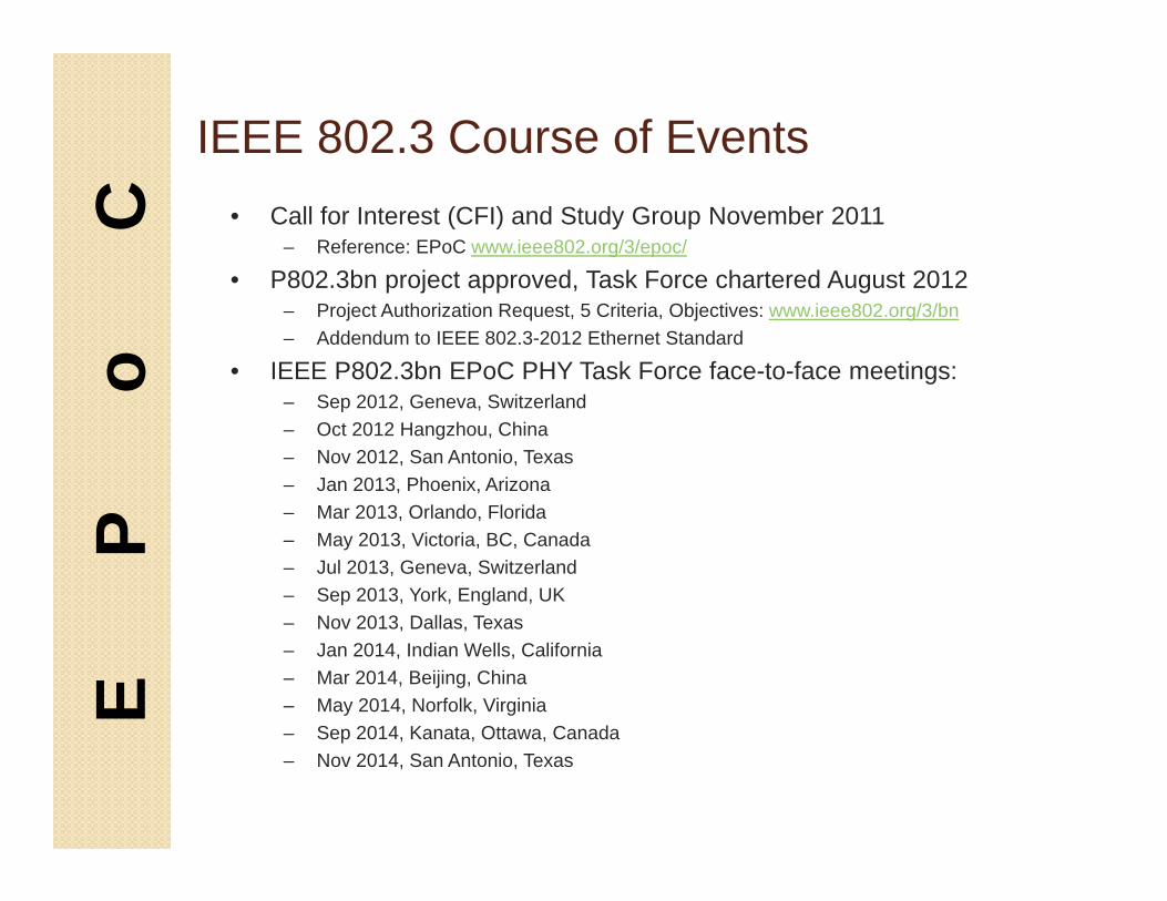
IEEE 802.3 Course of Events• Call for Interest (CFI) and Study Group November 2011
– Reference: EPoC www.ieee802.org/3/epoc/
• P802.3bn project approved, Task Force chartered August 2012– Project Authorization Request, 5 Criteria, Objectives: www.ieee802.org/3/bn– Addendum to IEEE 802.3-2012 Ethernet Standard
• IEEE P802.3bn EPoC PHY Task Force face-to-face meetings:– Sep 2012, Geneva, Switzerland– Oct 2012 Hangzhou, China– Nov 2012, San Antonio, Texas– Jan 2013, Phoenix, Arizona– Mar 2013, Orlando, Florida– May 2013, Victoria, BC, Canada– Jul 2013, Geneva, Switzerland– Sep 2013, York, England, UK– Nov 2013, Dallas, Texas– Jan 2014, Indian Wells, California– Mar 2014, Beijing, China– May 2014, Norfolk, Virginia– Sep 2014, Kanata, Ottawa, Canada– Nov 2014, San Antonio, Texas
E
P
o
C
Task Force Status Draft 1.1 comment resolution this meeting• Task Force Status: www.ieee802.org/3/bn/
– 143 Technical Decisions (updated 9/16/14)– Task Force Timeline (updated 7/16/14)
– Targeting March 2014 for Working Group ballot
– Current Work Items list
E
P
o
C
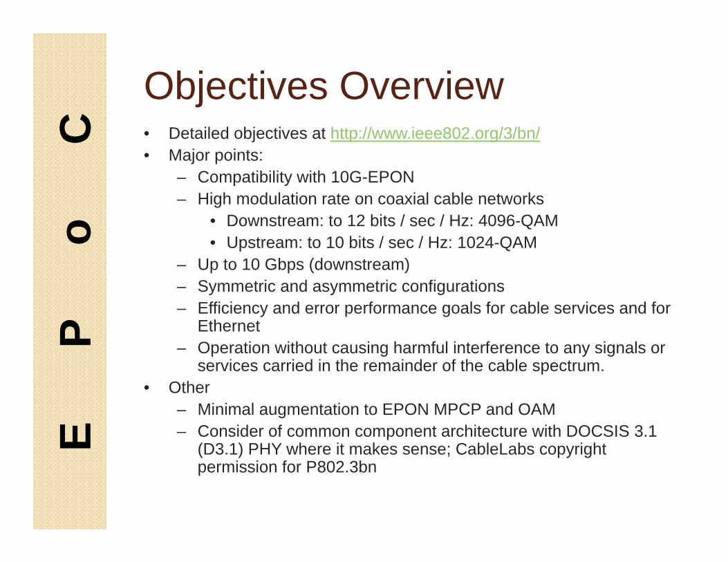
Objectives Overview• Detailed objectives at http://www.ieee802.org/3/bn/• Major points:
– Compatibility with 10G-EPON– High modulation rate on coaxial cable networks
• Downstream: to 12 bits / sec / Hz: 4096-QAM• Upstream: to 10 bits / sec / Hz: 1024-QAM
– Up to 10 Gbps (downstream)– Symmetric and asymmetric configurations– Efficiency and error performance goals for cable services and for
Ethernet– Operation without causing harmful interference to any signals or
services carried in the remainder of the cable spectrum.• Other
– Minimal augmentation to EPON MPCP and OAM– Consider of common component architecture with DOCSIS 3.1
(D3.1) PHY where it makes sense; CableLabs copyright permission for P802.3bn

E
P
o
C
Project Focus
APPLICATION
PRESENTATION
SESSION
TRANSPORT
NETWORK
DATA LINK
PHYSICAL
OAM (Optional)
MULTIPOINT MAC CONTROL (MPMC)
MAC – MEDIA ACCESS CONTROL
RECONCILLIATION
PCSPMAPMD
OSIREFERENCE
MODELLAYERS
HIGHER LAYERS
PHY
XGMII
MDI
Up to 10 Gbps
CLT – COAX LINE TERMINALCNU – COAX NETWORK UNITMDI – MEDIUM DEPENDENT INTERFACEOAM – OPERATIONS, ADMINISTRATION, & MAINTENANCE
PCS – PHYSICAL CODING SUBLAYERPHY – PHYSICAL LAYER DEVICEPMA – PHYSICAL MEDIUM ATTACHMENTPMD – PHYSICAL MEDIUM DEPENDENTXGMII – GIGABIT MEDIA INDEPENDENT INTERFACE
LLC (LOGICAL LINK CONTROL)OR OTHER MAC CLIENT
OAM (Optional)
MULTIPOINT MAC CONTROL (MPMC)
MAC – MEDIA ACCESS CONTROL
RECONCILLIATION
PCSPMAPMD
HIGHER LAYERS
PHY
XGMII
MDI
LLC (LOGICAL LINK CONTROL)OR OTHER MAC CLIENT
CLT CNU(s)
Up to 10 Gbps
COAX COAX
COAX
COAXDISTRIBUTION
NETWORKCABLE
MEDIUM
FOCUS
E
P
o
C
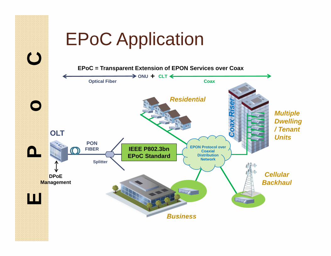
EPoC Application
Coa
x R
iser
Cellular Backhaul
Business
Residential
MultipleDwelling/ TenantUnits
EPON Protocol over Coaxial
DistributionNetwork
OLTPON
FIBER IEEE P802.3bnEPoC Standard
Splitter
DPoEManagement
EPoC = Transparent Extension of EPON Services over Coax+
Optical Fiber CoaxONU CLT
E
P
o
C
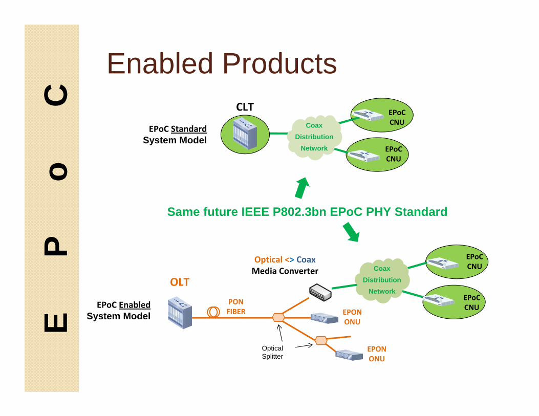
Enabled ProductsEPoC CNU
CLT
EPoC CNU
OLTPONFIBER
OpticalSplitter
EPONONU
CoaxDistribution
Network
Optical <> CoaxMedia Converter
EPoC CNU
EPoC CNUEPoC Enabled
System Model
EPONONU
CoaxDistribution
Network
Same future IEEE P802.3bn EPoC PHY Standard
EPoC StandardSystem Model
E
P
o
C
CableLabs EPoC Systems Specification Project
Defining: EPoC system and architecture based
on the IEEE P802.3bn PHY DPoE Extensions Fiber Conversion Unit (FCU); ◦ aka media converter◦ Bridge and repeater modes
and more
E
P
o
C
Overview of Challenges Cable industry push to gigabit services over
existing coax cable networks, includes:◦ Orthogonal Frequency Division Multiplexing
(OFDM)◦ “Next generation” Forward Error Correction Low Density Parity Coding (LDPC)
◦ Denser modulation rates 4096 QAM (12 bits/second/Hz) and beyond
◦ Multiple RF channel multiplexing (e.g. “bonding”)◦ Flexible configuration for matching to available RF
spectrum, channel conditions, and well known interference PHY layer data rate follows cable operator configuration
E
P
o
C
DownstreamDecisions to date:• LDPC FEC, single rate 14400/16200• 40‐bit CRC per information word to meet 802.3 MTTFPA• OFDM 192 MHz, 4K FFT, 3800 50 KHz subcarriers per channel
• Subcarrier use types: excluded, data, PHY Link, continuous pilots• 24 MHz minimum RF spectrum• PHY Link channel
• Well known configuration and placement in RF spectrum; • easily discoverable
• Used for PHY discovery, initialization, ranging, and maintenance • Performs Ethernet “link negotiation”
• Repeating 128 symbol cycle SuperframeDownstream (and Upstream) Challenges:• IEEE 802.3 layer model and conventions• Rate matching to 10 Gbps EPON XGMII• Multiple OFDM channels multiplexed for operation up to 10 Gbps

E
P
o
C
UpstreamDecisions:• LDPC FEC, 3 code word rates/sizes (similar to D3.1)• 40‐bit CRC per information word• OFDMA 192 MHz, 4K FFT, 3800 50 KHz subcarriers• Single channel. RF spectrum: 10 MHz minimum to 192 MHzChallenges:• OFDMA “Super Frame” concept to organize various signal types:
• Frame size: 5 or 6 probe symbols + 256 symbols, repeating• Wide band probes: OFDM timing, synchronization, channel
estimation• PHY Link channel
• PHY Discovery, Fine Ranging• Resource Blocks for MAC data, pilots,
• Resource Blocks (RBs): 8 or 16 symbols in time, 1 subcarrier in frequency contain: data, pilots, start / end burst marker
E
P
o
C
CABLE NETWORK REQUIREMENTS
E
P
o
C
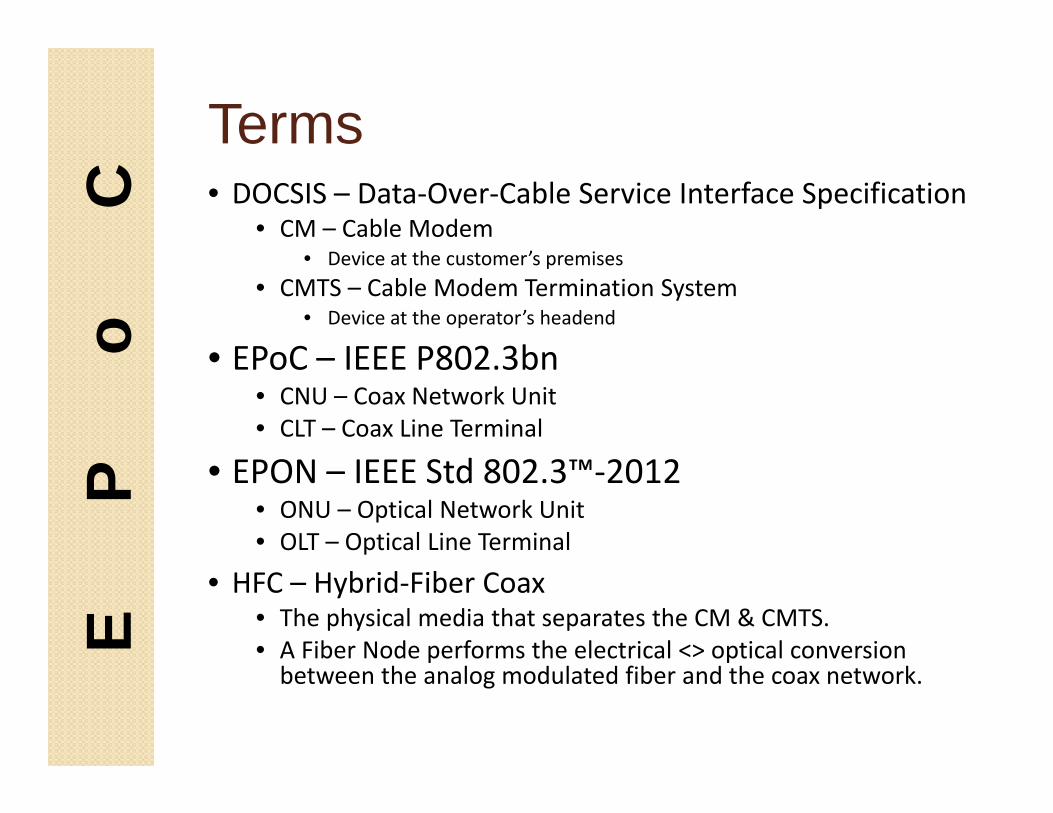
Terms• DOCSIS – Data‐Over‐Cable Service Interface Specification
• CM – Cable Modem• Device at the customer’s premises
• CMTS – Cable Modem Termination System • Device at the operator’s headend
• EPoC – IEEE P802.3bn• CNU – Coax Network Unit• CLT – Coax Line Terminal
• EPON – IEEE Std 802.3™‐2012• ONU – Optical Network Unit• OLT – Optical Line Terminal
• HFC – Hybrid‐Fiber Coax• The physical media that separates the CM & CMTS. • A Fiber Node performs the electrical <> optical conversion between the analog modulated fiber and the coax network.
E
P
o
C
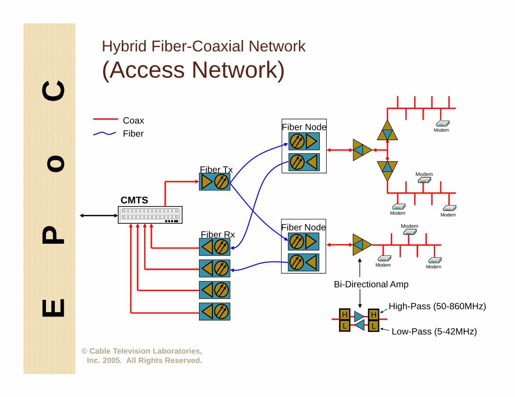
Hybrid Fiber-Coaxial Network
(Access Network)
© Cable Television Laboratories, Inc. 2005. All Rights Reserved.
CMTS
Fiber Node
Fiber NodeModem
Modem
Modem
Modem
Fiber Tx
Fiber Rx
CoaxFiber
Bi-Directional Amp
Modem
Modem
Modem
HL
HL
High-Pass (50-860MHz)
Low-Pass (5-42MHz)
E
P
o
C
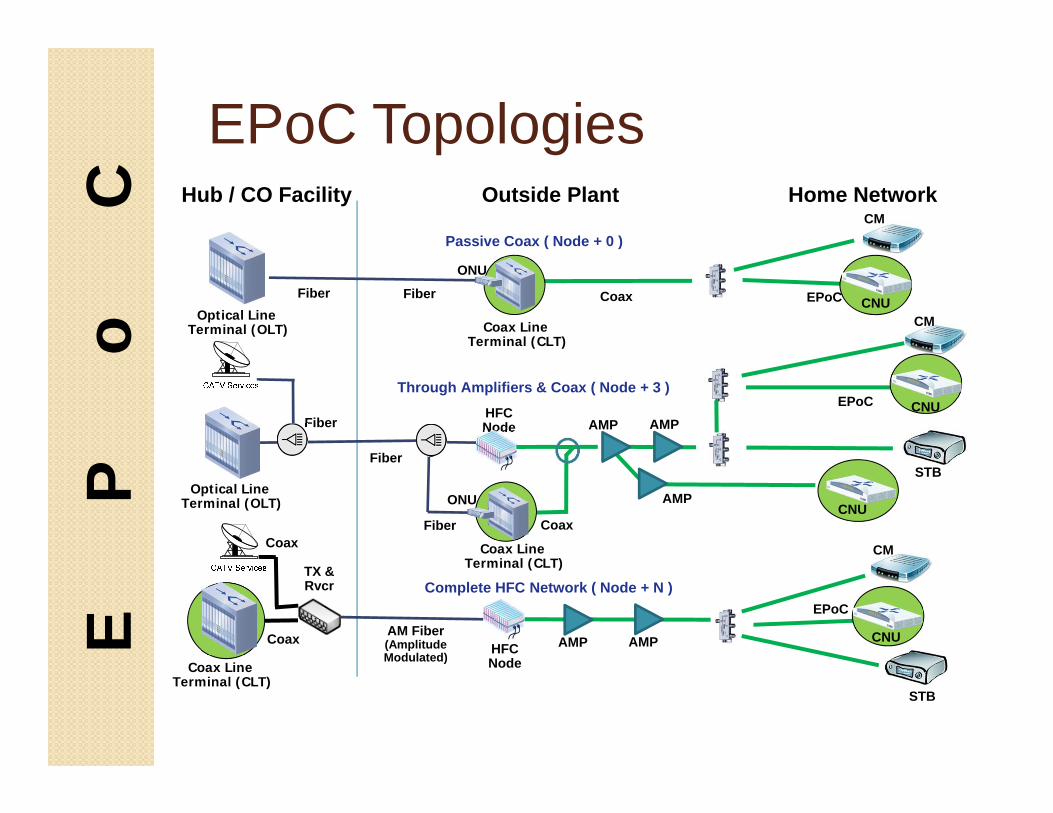
EPoC Topologies
Optical Line Terminal (OLT)
O/E
Through Amplifiers & Coax ( Node + 3 )
CM
CNU
STB
CoaxFiber
HFC NodeFiber AMP
AMP
EPoCAMP
O/E
Fiber
AM Fiber(Amplitude Modulated)
Coax
Fiber Fiber
CM
CNUEPoC
CM
CNU
EPoC
STB
Passive Coax ( Node + 0 )
AMP AMP
Optical Line Terminal (OLT)
Coax Line Terminal (CLT)
Outside PlantHub / CO Facility Home Network
HFC Node
Coax Line Terminal (CLT)
Coax Line Terminal (CLT)TX &
Rvcr
Coax
Coax
ONU
ONU
Complete HFC Network ( Node + N )
CNU
E
P
o
C
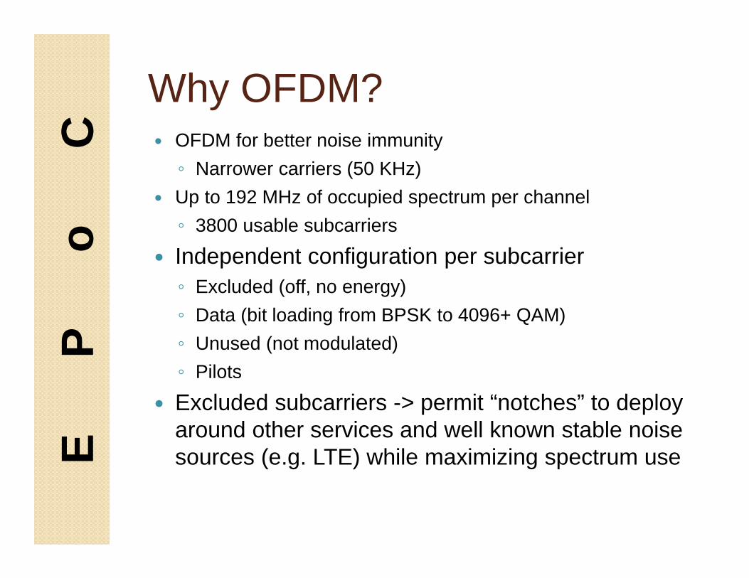
Why OFDM? OFDM for better noise immunity◦ Narrower carriers (50 KHz)
Up to 192 MHz of occupied spectrum per channel◦ 3800 usable subcarriers
Independent configuration per subcarrier◦ Excluded (off, no energy)◦ Data (bit loading from BPSK to 4096+ QAM)◦ Unused (not modulated)◦ Pilots
Excluded subcarriers -> permit “notches” to deploy around other services and well known stable noise sources (e.g. LTE) while maximizing spectrum use
E
P
o
C
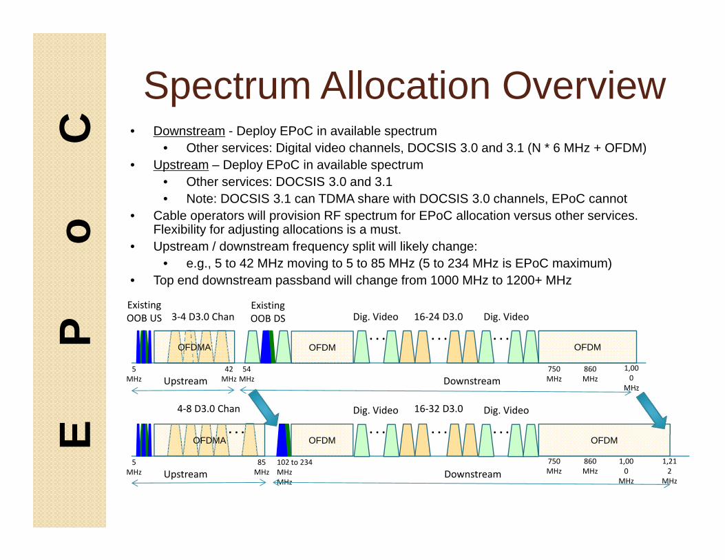
Spectrum Allocation Overview• Downstream - Deploy EPoC in available spectrum
• Other services: Digital video channels, DOCSIS 3.0 and 3.1 (N * 6 MHz + OFDM)• Upstream – Deploy EPoC in available spectrum
• Other services: DOCSIS 3.0 and 3.1• Note: DOCSIS 3.1 can TDMA share with DOCSIS 3.0 channels, EPoC cannot
• Cable operators will provision RF spectrum for EPoC allocation versus other services. Flexibility for adjusting allocations is a must.
• Upstream / downstream frequency split will likely change: • e.g., 5 to 42 MHz moving to 5 to 85 MHz (5 to 234 MHz is EPoC maximum)
• Top end downstream passband will change from 1000 MHz to 1200+ MHz
54 MHz
750MHz
5MHz
42MHz
860MHz
1,000
MHz
3‐4 D3.0 Chan 16‐24 D3.0
. . .
Upstream
ExistingOOB DS
Existing OOB US
OFDM
Downstream
OFDMA
102 to 234 MHzMHz
750MHz
5MHz
85MHzUpstream
16‐32 D3.04‐8 D3.0 Chan
OFDM
860MHz
1,000
MHz
1,212
MHz
OFDMOFDMA
Downstream
OFDM
. . .
. . . . . .Dig. Video Dig. Video
. . . . . .Dig. Video Dig. Video
. . .
E
P
o
C
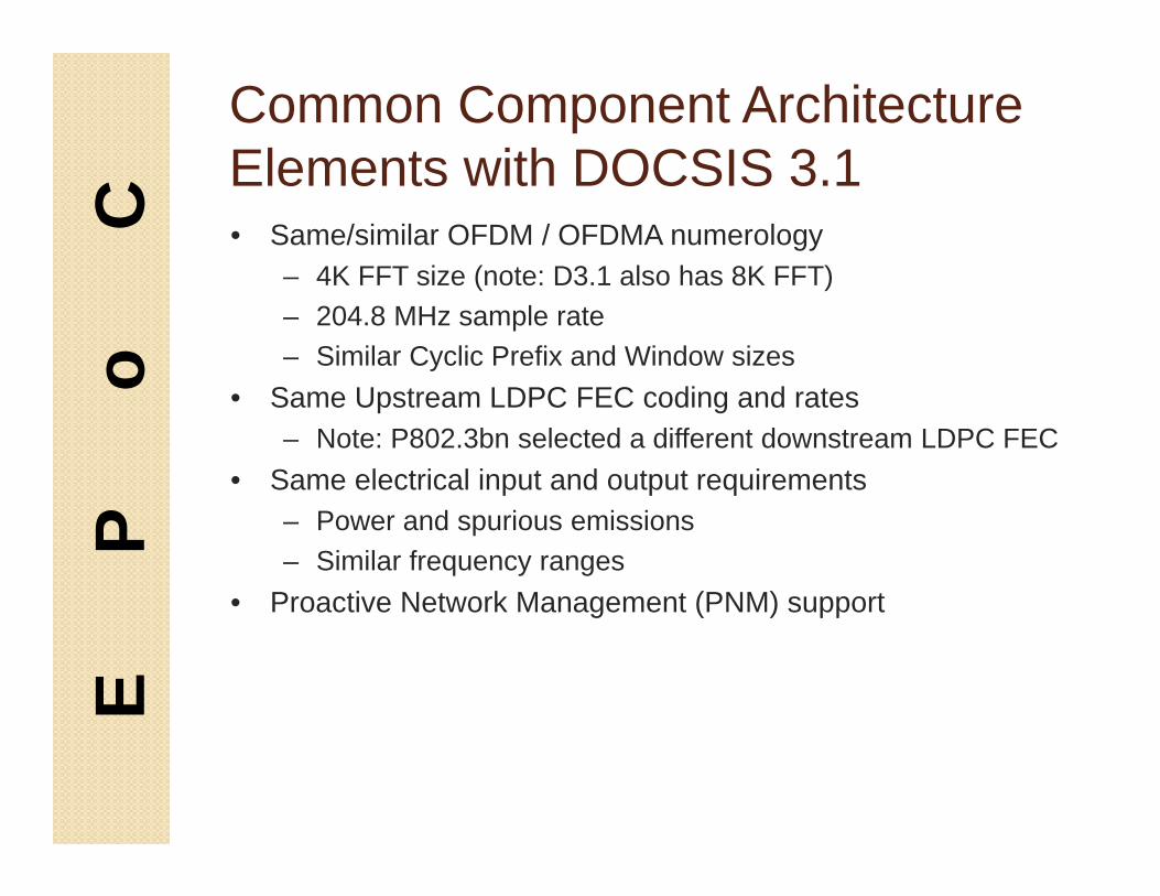
Common Component Architecture Elements with DOCSIS 3.1• Same/similar OFDM / OFDMA numerology
– 4K FFT size (note: D3.1 also has 8K FFT)– 204.8 MHz sample rate– Similar Cyclic Prefix and Window sizes
• Same Upstream LDPC FEC coding and rates– Note: P802.3bn selected a different downstream LDPC FEC
• Same electrical input and output requirements– Power and spurious emissions– Similar frequency ranges
• Proactive Network Management (PNM) support
E
P
o
C
PHY LINK CHANNEL

E
P
o
C
PHY LinkWhat is it & Why do we need it Separate link used to establish OFDM &
OFDMA channel parameters:◦ DS Number of OFDM channels◦ US & DS channel frequency bounds; upper
extreme, lower extreme, internally excluded bands◦ US & DS channel profile; modulation level for
each of the 4096 subcarriers◦ DS & US Cyclic Prefix, Windowing & Time
interleaving parameters◦ US PHY Link frequency and OFDMA frame
parameters: Probe Period size (5/6 symbols), Pilot pattern
E
P
o
C
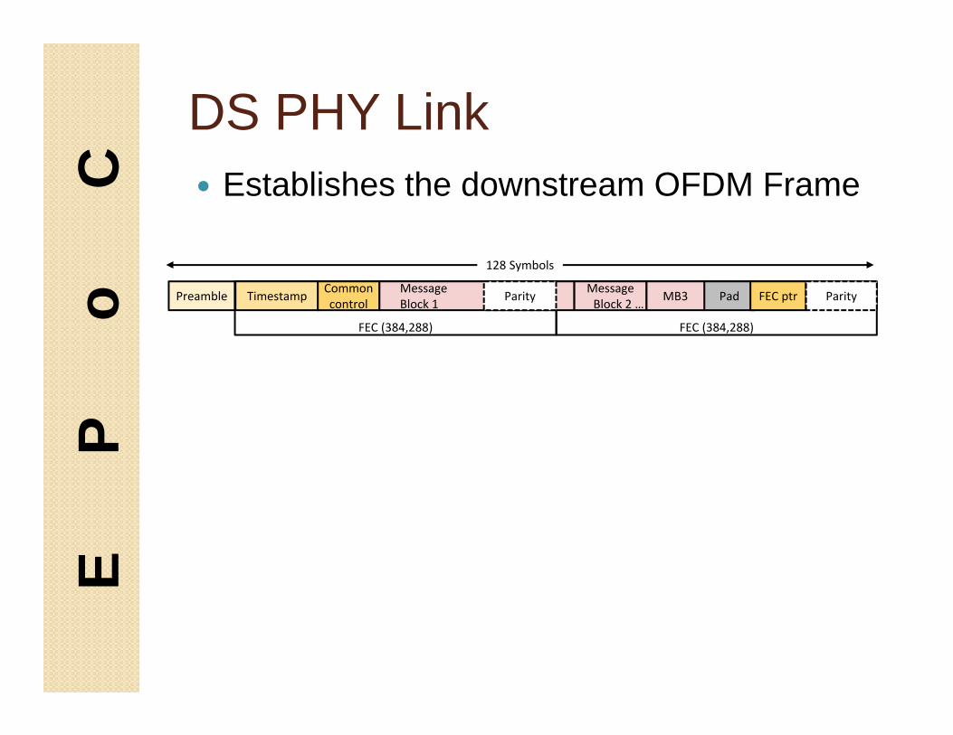
DS PHY Link Establishes the downstream OFDM Frame
128 Symbols
FEC (384,288)FEC (384,288)
Preamble MessageBlock 1Timestamp Common
control Pad FEC ptrParity ParityMessageBlock 2 … MB3
E
P
o
C
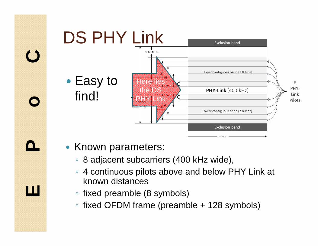
Easy to find!
Known parameters:◦ 8 adjacent subcarriers (400 kHz wide), ◦ 4 continuous pilots above and below PHY Link at
known distances◦ fixed preamble (8 symbols)◦ fixed OFDM frame (preamble + 128 symbols)
Here lies the DS
PHY Link
DS PHY Link
E
P
o
C
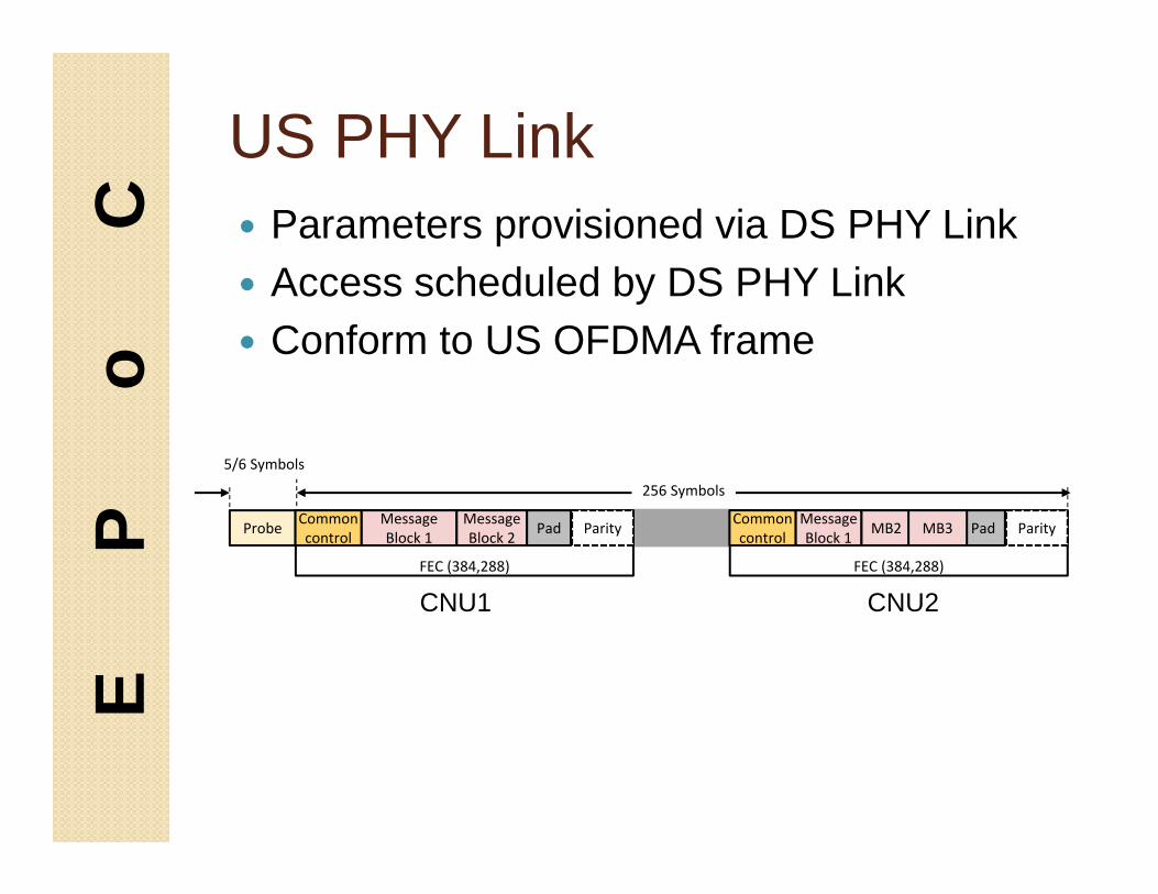
US PHY Link Parameters provisioned via DS PHY Link Access scheduled by DS PHY Link Conform to US OFDMA frame
256 Symbols
FEC (384,288)
Probe MessageBlock 1
Commoncontrol ParityMessage
Block 2 Pad
FEC (384,288)
MessageBlock 1
Commoncontrol ParityMB2 PadMB3
CNU1 CNU2
5/6 Symbols
E
P
o
C
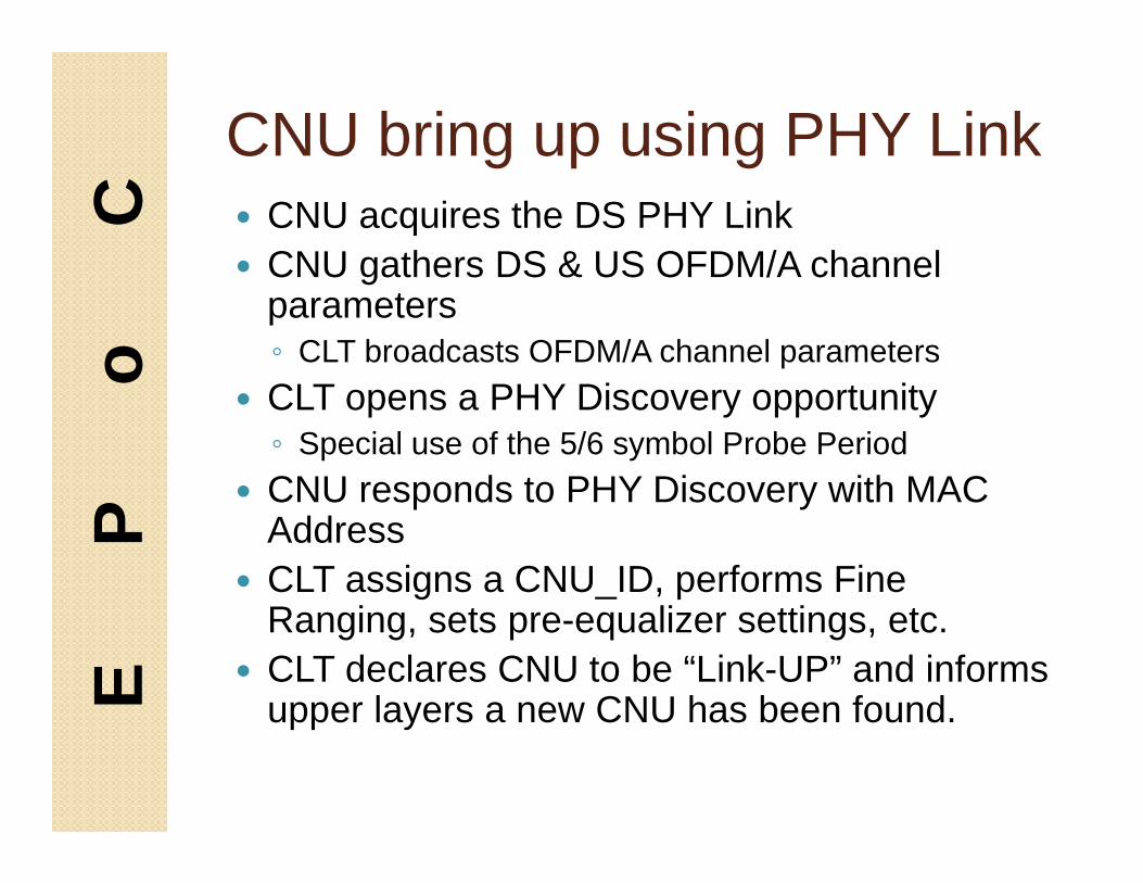
CNU bring up using PHY Link CNU acquires the DS PHY Link CNU gathers DS & US OFDM/A channel
parameters◦ CLT broadcasts OFDM/A channel parameters
CLT opens a PHY Discovery opportunity◦ Special use of the 5/6 symbol Probe Period
CNU responds to PHY Discovery with MAC Address
CLT assigns a CNU_ID, performs Fine Ranging, sets pre-equalizer settings, etc.
CLT declares CNU to be “Link-UP” and informs upper layers a new CNU has been found.
E
P
o
C
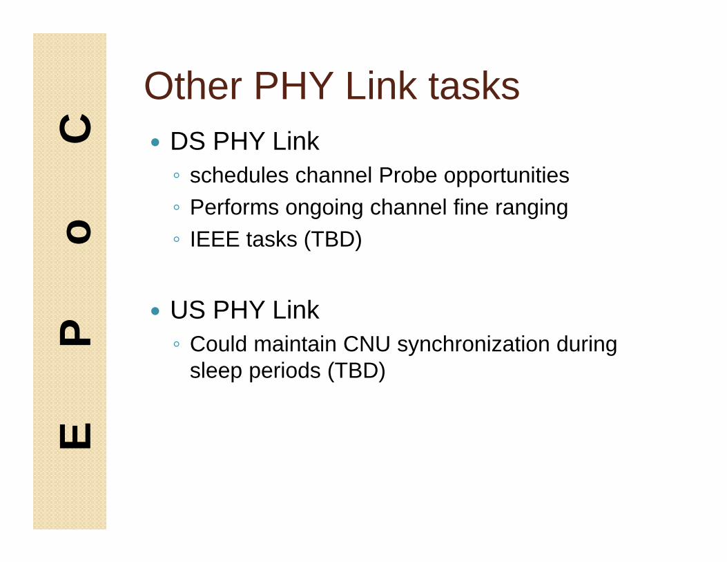
Other PHY Link tasks DS PHY Link◦ schedules channel Probe opportunities◦ Performs ongoing channel fine ranging◦ IEEE tasks (TBD)
US PHY Link◦ Could maintain CNU synchronization during
sleep periods (TBD)
E
P
o
C
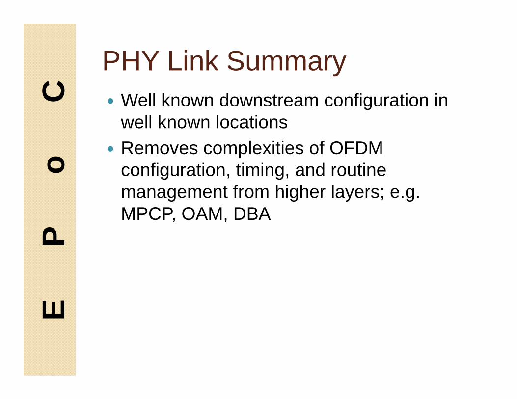
PHY Link Summary Well known downstream configuration in
well known locations Removes complexities of OFDM
configuration, timing, and routine management from higher layers; e.g. MPCP, OAM, DBA
E
P
o
C
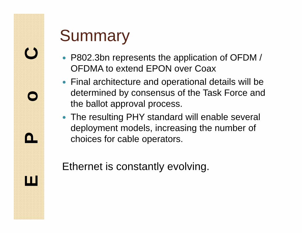
Summary P802.3bn represents the application of OFDM /
OFDMA to extend EPON over Coax Final architecture and operational details will be
determined by consensus of the Task Force and the ballot approval process.
The resulting PHY standard will enable several deployment models, increasing the number of choices for cable operators.
Ethernet is constantly evolving.
E
P
o
C
Q&A

E
P
o
C
Questions: Was this tutorial worthwhile? Should we plan to do a Part 2 for next plenary?◦ Downstream / upstream framing◦ Upstream 1D to 2D mapping
E
P
o
C
THANK YOU!!