ep0878712 standardization of chromatographic systems
TRANSCRIPT
Note: Within nine months of the publication of the mention of the grant of the European patent in the European PatentBulletin, any person may give notice to the European Patent Office of opposition to that patent, in accordance with theImplementing Regulations. Notice of opposition shall not be deemed to have been filed until the opposition fee has beenpaid. (Art. 99(1) European Patent Convention).
Printed by Jouve, 75001 PARIS (FR)
(19)E
P0
878
712
B1
TEPZZZ8787_ B_T(11) EP 0 878 712 B1
(12) EUROPEAN PATENT SPECIFICATION
(45) Date of publication and mention of the grant of the patent: 01.01.2014 Bulletin 2014/01
(21) Application number: 98109041.8
(22) Date of filing: 18.05.1998
(51) Int Cl.:G01N 30/88 (2006.01) G01N 30/86 (2006.01)
(54) Standardization of chromatographic systems
Standardisierung chromatographischer Systeme
Standardisation de systèmes chromatographiques
(84) Designated Contracting States: DE FR GB
(30) Priority: 16.05.1997 US 46671 P
(43) Date of publication of application: 18.11.1998 Bulletin 1998/47
(73) Proprietor: PerkinElmer Health Sciences, Inc.Waltham, MA 02451 (US)
(72) Inventors: • Tipler, Andrew
Trumbull, CT 06611 (US)• Patkin, Adam J.,
Hamden,CT 06517 (US)• Bajorinas, Andrew J.
Stamford, CT 06902 (US)• Cahill, Jerry E.
Trumbull, CT 06611 (US)• Carter, Ralph
Thame, Oxon (GB)
(74) Representative: Jehle, Volker Armin et alBosch Jehle Patentanwaltsgesellschaft mbH Flüggenstrasse 1380639 München (DE)
(56) References cited: US-A- 5 405 432 US-A- 5 476 000US-A- 5 545 895 US-A- 5 559 728
• J. CURVERS ET AL: ’Temperature programmed retention indices: Calculation from isothermal data. Part 1: Theory’ JOURNAL OF HIGH RESOLUTION CHROMATOGRAPHY vol. 8, no. 9, 01 September 1985, pages 607 - 610, XP055010145 DOI: 10.1002/jhrc.1240080926 ISSN: 0935-6304
• J. CURVERS ET AL: ’Temperature programmed retention indices: Calculation from isothermal data. Part 2: Results with nonpolar columns’ JOURNAL OF HIGH RESOLUTION CHROMATOGRAPHY vol. 8, no. 9, 01 September 1985, pages 611 - 617, XP055010146 DOI: 10.1002/jhrc.1240080927 ISSN: 0935-6304
EP 0 878 712 B1
2
5
10
15
20
25
30
35
40
45
50
55
Description
[0001] This invention relates to chromatographic systems and particularly to the standardization of such systems.
BACKGROUND
[0002] Chromatography involves physically separating constituents of a sample in a carrier fluid and measuring theseparation. In gas chromatography (GC) the carrier is a gas or at least a supercritical fluid which acts similarly in thesystem. In liquid chromatography (LC) the carrier is a liquid. In either case a pulse of the sample is injected into a steadyflow of the carrier, and the constituents are adsorbed or absorbed and desorbed by a stationary phase material in acolumn. At the end of the column the individual components are more or less separated in time. Monitoring the columneffluent with a suitable detector provides a pattern of retention times which, by calibration or comparison with knownsamples, indicates the constituents of the sample qualitatively and quantitatively. The main components of such a systemare the column, an injector with a mixing chamber for introducing the sample into the carrier, a detector at the outlet endof the column, fluid controls, and a computer for processing and displaying the output of the detector. The display isgenerally in the form of retention times. In GC an oven generally is used to elevate temperature to maintain the samplein a volatile state, and to improve the discrimination of constituents. Various gas chromatographic systems are disclosedin U.S. patent Nos. 5,405,432, 5,545,252 ("Hinshaw 1"), U.S. patent application serial No. 08/734,689 filed October 21,1996 ("Hinshaw 2"), and an article "The Effects of Inlet Liner Configuration and Septum Purge Flow Rate on Discriminationin Splitless Injection" by J.V. Hinshaw, J. High Resolution Chromatography 16, 247-253 (April 1993). A liquid chroma-tographic system is disclosed in U.S. patent No. 4,579,663.[0003] Interpretations of retention time patterns in chromatography tend to require skill and experience, as differentsystems and particularly different columns behave differently so as to effect different patterns for the same samplematerial. An operator selects operating parameters, such as temperature and pressure, or may vary these parametersduring a run, according to judgment. Thus uses of these systems for evaluating samples is dependent on the skills ofthe operators, and it has been difficult to compare results of different systems, columns and operators.[0004] When a chromatographic method is developed it is often desirable to transfer it to the same system at a latertime, the same system with a different column, or another system. The task is made more complicated by other factorsincluding different calibrations of temperatures and pressures, and different oven geometries resulting in different tem-perature gradients. Differing characteristics of columns include length, internal diameter, phase thickness and phasechemistry, and these characteristics are difficult to determine with precision without destroying the column. These var-iations in systems, particularly columns, cause the retention times to change for different systems and the same systemat different times, even switching the order of some peaks. Recalibration is complex and can be time consuming.Standardization would be desirable, such as is done in optical spectroscopy, for example as disclosed in U.S. patentNo. 5,303,165 (Ganz et al.) It would be particularly desirable to be able to provide a useful library of basic standardsassociated with specified types of columns, so that chromatographic results may be compared universally.[0005] US 5,405,432 describes a computer-based method of controlling a gas chromatograph running system softwareto produce a new chromatographic output by automatically reconfiguring existing operating parameters of the gas chro-matograph in response to the input of new column parameters and a new column, said new chromatographic outputbeing substantially equivalent to a known chromatographic output of a known chromatographic method having bothexisting column parameters and existing operating parameters, comprising the steps of: storing existing column param-eters and existing operating parameters of the known chromatographic method on the system software; and storingknown translation equations on the system software, said translation equations being based on the ratio of new columnparameters to existing column parameters; and inputting new column parameters corresponding to said new columninto the system software; and calculating the ratios between new column parameters and existing column parameters;and calculating new operating parameters based on the ratios between new column parameters and existing columnparameters; and automatically reconfiguring the existing operating parameters of said gas chromatograph with said newoperating parameters.[0006] Objects of the invention are to provide a novel method and a novel means for standardizing chromatographicsystems so as to allow direct comparison of information generated from different systems and the same system atdifferent times, including different chromatographic columns and the same column at different times. Particular objectsare to provide a novel method and a novel means for establishing certain operating parameters for each chromatographicsystem such that retention times are substantially identical for different systems and the same system at different times.Other objects are to provide a novel method and a novel means for optimizing parameters for chromatographic systems.Additional objects are to provide a novel method and a novel means for measuring temperature of chromatographiccolumns, particularly to further standardization, and also to provide a novel method and a novel means for validatingchromatographic systems.
EP 0 878 712 B1
3
5
10
15
20
25
30
35
40
45
50
55
SUMMARY OF THE INVENTION
[0007] The foregoing and other objects are achieved, at least in part, by a method and a means for standardizing atarget chromatographic system with a primary chromatographic system. Each system includes carrier means for passinga fluid carrier through the column, injection means for injecting a pulse of sample into the carrier to effect a mixturepassing through the column subject to characteristic retention times for constituents of the sample, detector meansreceptive of the mixture for effecting signals representative of the retention times, and processing means receptive ofthe signals for presenting corresponding retention indicators. Each system has system parameters and operating pa-rameters, the operating parameters comprising a first parameter having selectable first programming and a secondparameter having selectable second programming, each programming being with respect to time. The retention timesare related to the system parameters and the operating parameters by a mathematical function having function parametersincluding thermodynamic constants associated with interactions of the constituents with the column.[0008] In preferred embodiments, the system is a gas chromatographic system with a gas carrier, the first parameteris column temperature and the second parameter is inlet pressure of the carrier to the column. Also, preferably, theretention indicators are retention times, and the system parameters include column dimensions.[0009] The primary system is operated with a standard sample, a selected primary second program (e.g. pressure)for the second parameter, and a plurality of selected primary first programs (e.g. temperature) for the first parameter,so as to generate corresponding primary retention indicators (e.g. times). The primary retention indicators and the firstprograms are fitted to the function, with the second program, so as to determine thermodynamic constants whereby thefunction is representative of a virtual chromatographic system. The thermodynamic constants are stored for futureapplication with the target chromatographic system.[0010] A target chromatographic system is initially operated with the standard sample, substantially the primary secondprogram, and a plurality of secondary first programs, so as to generate corresponding secondary retention indicators.Effective system parameters (e.g. column dimensions) are established for the target chromatographic system, by as-sumption, earlier measurement or a technique according to an aspect of the invention (explained below). A secondarysecond program then is determined for which, with the effective system parameters, the function yields substantially theprimary retention indicators for the primary first programs.[0011] In an actual operation, the target chromatographic system is operated with a application sample, the secondarysecond program and a selected first program, so as to generate at least one corresponding test retention indicator. Byuse of such secondary program, each test retention indicator is standardized to the virtual chromatographic system.[0012] The function relating retention times to the parameters such as temperature and pressure are based preferablyon theoretical relationships of a chromatographic system. As such a function generally is complex, special techniquesmay be required for its application, particularly in the determination of an effective column dimension and a secondarysecond (pressure) program. In an aspect of the invention, a method and a means are provided for determining valuesfor one or more specified parameters for a chromatographic system. There are system parameters (e.g. column dimen-sions) and operating parameters (e.g. temperature and pressure) related to retention times by a mathematical functionhaving function parameters including these parameters as well as others such as thermodynamic constants related tointeractions of the sample with a stationary phase in the column. The function parameters have predetermined or assumedvalues except for the specified parameters. A specified parameter may be column inlet pressure, or column length.[0013] The system (e.g. target system) is operated so as to generate retention indicators. An initial data base isprovided, defining ranges of potential values of the specified parameter or parameters. Theoretical retention indicatorsare computed with the function for the potential values and the predetermined or assumed values, differences arecomputed between the theoretical retention indicators and the secondary retention indicators, and the differences aresearched for a minimum therein, such that the minimum establishes an effective value for each specified parameter.[0014] In another aspect a method and a means are provided to determine column temperature of the target chroma-tographic system relative to that of the primary chromatographic system. A temperature standard is provided comprisinga calibration compound having temperature dependent retention time, and a plurality of homolog standards having ahomolog relationship between corresponding retention indicators and retention times. The primary chromatographicsystem is operated with the temperature standard, a selected primary pressure program and a plurality of selectedcalibration temperatures so as to generate a primary set of retention times for each calibration temperature, each primaryset comprising homolog retention times for the homolog standards and a compound retention time for the calibrationcompound. The homolog relationship and the primary set of retention times are first utilized for each calibration temper-ature to determine calibration constants for a temperature relationship relating retention indicator for the calibrationcompound to column temperature for the primary system. The target chromatographic system is operated with thetemperature standard and a measured column temperature so as to generate a test set of retention times, the test setcomprising test retention times for the homolog standards, and a test retention time for the calibration compound. Thehomolog relationship and the test set of retention times are secondly utilized to determine a secondary retention indicatorfor the calibration compound. The temperature relationship is applied with the calibration constants and the secondary
EP 0 878 712 B1
4
5
10
15
20
25
30
35
40
45
50
55
retention indicator to determine a calibrated temperature corresponding to the measured temperature.[0015] In a further aspect a method and a means are provided for validating a target gas chromatographic systemhaving a calibrated temperature relationship between its column temperature and the column temperature for a primarygas chromatographic system. A validation standard is provided comprising selected validation constituents and a pluralityof homolog standards having a homolog relationship between corresponding retention indicators and retention times.The primary chromatographic system is operated with the validation standard, a selected primary pressure program,and a primary validation temperature for the column, so as to generate primary validation retention times for the validationconstituents and homolog retention times for the homolog standards. The target chromatographic system is operatedwith the validation standard, substantially the primary pressure program, and the measured column temperature so asto generate secondary validation retention times for the validation constituents and test retention times for the homologstandards. The homolog retention times are utilized to determine primary homolog parameters for the homolog relation-ship, and the test retention times are utilized to determine secondary homolog parameters for the homolog relationship.The homolog relationship, the primary homolog parameters and the primary validation retention times are utilized toeffect preliminary retention indicators. The homolog relationship, the secondary homolog parameters and the secondaryvalidation retention times are utilized to effect secondary validation retention indicators. The preliminary retention indi-cators are adjusted with the temperature relationship to a calibrated temperature corresponding to the secondaryvalidation temperature so as to effect primary validation retention indicators. Differences between corresponding primaryvalidation retention indicators and secondary validation retention indicators are calculated, and it is determined whetherthe differences are less than a predetermined limit corresponding to whether the target chromatographic system is valid.
BRIEF DESCRIPTION OF THE DRAWINGS
[0016]
FIG. 1 is a schematic drawing of a chromatographic system incorporating the invention.
FIG. 2 is a longitudinal section of a portion of a chromatographic column used in the system of FIG. 1.
FIG. 3A and FIG. 3B are a flow chart of a method and a means for carrying out an embodiment of the invention forstandardization of a system of FIG. 1.
FIG. 4 is an illustration of a series of peaks representing chromatographic retention times of constituents such asfrom a sample utilized with the system of FIG. 1.
FIG. 5 is a flow chart of a method and a means for applying a function in the embodiment of FIG. 3.
FIG. 6 is a flow chart of an additional method and an additional means for applying the function in the embodimentof FIG. 3.
FIG. 7 is a flow chart of a method and a means for calibrating temperature of the column of the system of FIG. 1.
FIG. 8 is a flow chart of a method and a means for validating the system of FIG. 1.
DETAILED DESCRIPTION
[0017] The invention is utilized in an otherwise conventional or other desired gas chromatographic (GC) system suchas described in the aforementioned U.S. patent No. 5,545,252 ("Hinshaw 1") and U.S. patent application serial No.08/734,689 ("Hinshaw 2"), each being of the present assignee and incorporated herein in its entirety by reference. Asuitable system is a Perkin-Elmer Autosystem XL (trademark).[0018] A preferred type of GC system 10 (FIG. 1) utilizes split flow with back pressure regulation in the manner illustratedin the aforementioned Hinshaw article, figure 2(b) thereof. A carrier gas from a pressure-regulated source 12 is suppliedthrough a gas flow controller 14 to an injector device 16, each of which may be essentially any conventional or otherdesired type. For example, the flow controller is of the type taught in Hinshaw 2, and the injector is of the type taught inHinshaw 1. A portion of the carrier is passed from the injector 16 into and through a chromatographic column 18 formedof a long tube, e.g a fused silica tube 25 m long and 0.25 mm inside diameter, having a selected stationary phase onthe inside column wall such as methyl silicone 0.25 mm thick.[0019] Most of the remainder of the inlet flow passes out to the ambient space (normally atmosphere) through a backpressure regulator 13, for example as taught in Hinshaw 2, so as to maintain a constant, selected pressure of carrier
EP 0 878 712 B1
5
5
10
15
20
25
30
35
40
45
50
55
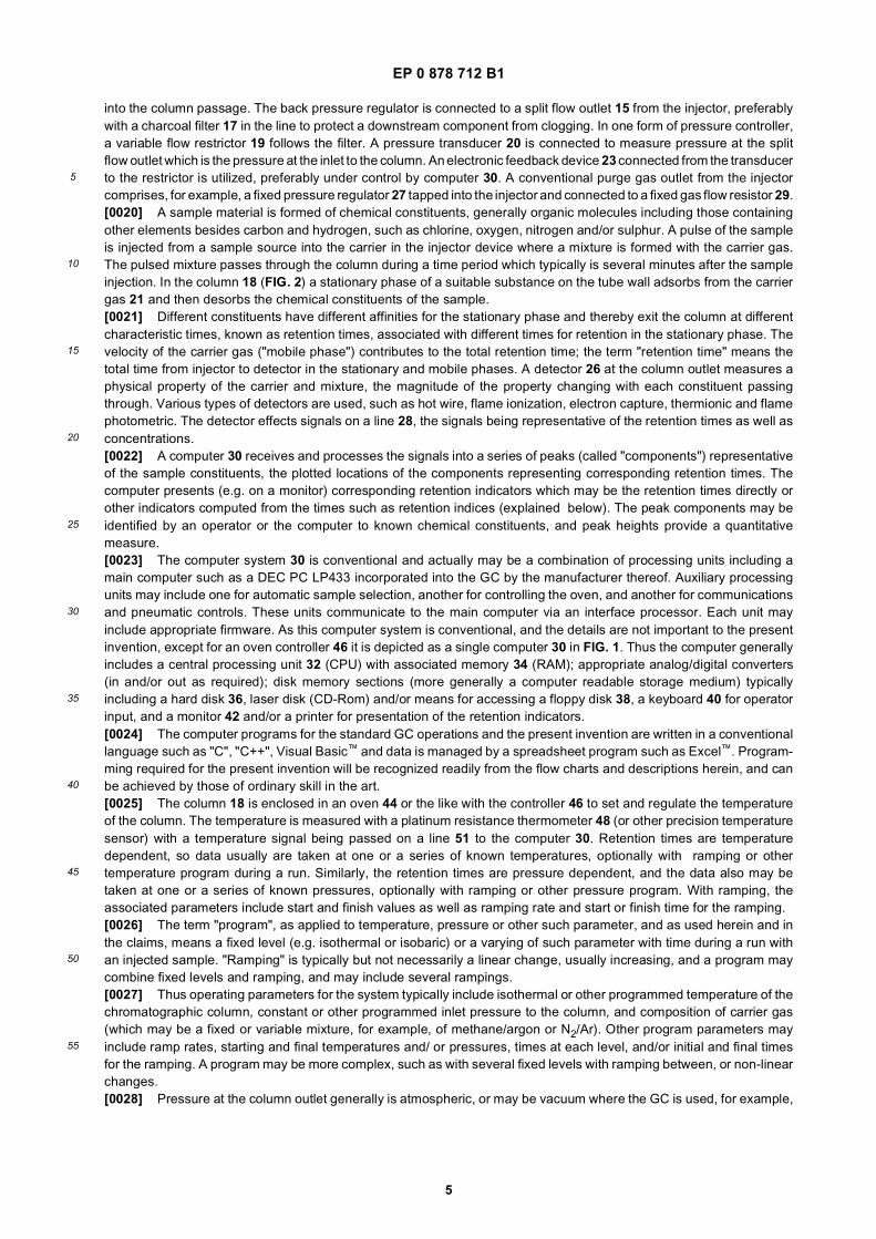
into the column passage. The back pressure regulator is connected to a split flow outlet 15 from the injector, preferablywith a charcoal filter 17 in the line to protect a downstream component from clogging. In one form of pressure controller,a variable flow restrictor 19 follows the filter. A pressure transducer 20 is connected to measure pressure at the splitflow outlet which is the pressure at the inlet to the column. An electronic feedback device 23 connected from the transducerto the restrictor is utilized, preferably under control by computer 30. A conventional purge gas outlet from the injectorcomprises, for example, a fixed pressure regulator 27 tapped into the injector and connected to a fixed gas flow resistor 29.[0020] A sample material is formed of chemical constituents, generally organic molecules including those containingother elements besides carbon and hydrogen, such as chlorine, oxygen, nitrogen and/or sulphur. A pulse of the sampleis injected from a sample source into the carrier in the injector device where a mixture is formed with the carrier gas.The pulsed mixture passes through the column during a time period which typically is several minutes after the sampleinjection. In the column 18 (FIG. 2) a stationary phase of a suitable substance on the tube wall adsorbs from the carriergas 21 and then desorbs the chemical constituents of the sample.[0021] Different constituents have different affinities for the stationary phase and thereby exit the column at differentcharacteristic times, known as retention times, associated with different times for retention in the stationary phase. Thevelocity of the carrier gas ("mobile phase") contributes to the total retention time; the term "retention time" means thetotal time from injector to detector in the stationary and mobile phases. A detector 26 at the column outlet measures aphysical property of the carrier and mixture, the magnitude of the property changing with each constituent passingthrough. Various types of detectors are used, such as hot wire, flame ionization, electron capture, thermionic and flamephotometric. The detector effects signals on a line 28, the signals being representative of the retention times as well asconcentrations.[0022] A computer 30 receives and processes the signals into a series of peaks (called "components") representativeof the sample constituents, the plotted locations of the components representing corresponding retention times. Thecomputer presents (e.g. on a monitor) corresponding retention indicators which may be the retention times directly orother indicators computed from the times such as retention indices (explained below). The peak components may beidentified by an operator or the computer to known chemical constituents, and peak heights provide a quantitativemeasure.[0023] The computer system 30 is conventional and actually may be a combination of processing units including amain computer such as a DEC PC LP433 incorporated into the GC by the manufacturer thereof. Auxiliary processingunits may include one for automatic sample selection, another for controlling the oven, and another for communicationsand pneumatic controls. These units communicate to the main computer via an interface processor. Each unit mayinclude appropriate firmware. As this computer system is conventional, and the details are not important to the presentinvention, except for an oven controller 46 it is depicted as a single computer 30 in FIG. 1. Thus the computer generallyincludes a central processing unit 32 (CPU) with associated memory 34 (RAM); appropriate analog/digital converters(in and/or out as required); disk memory sections (more generally a computer readable storage medium) typicallyincluding a hard disk 36, laser disk (CD-Rom) and/or means for accessing a floppy disk 38, a keyboard 40 for operatorinput, and a monitor 42 and/or a printer for presentation of the retention indicators.[0024] The computer programs for the standard GC operations and the present invention are written in a conventionallanguage such as "C", "C++", Visual Basic™ and data is managed by a spreadsheet program such as Excel™. Program-ming required for the present invention will be recognized readily from the flow charts and descriptions herein, and canbe achieved by those of ordinary skill in the art.[0025] The column 18 is enclosed in an oven 44 or the like with the controller 46 to set and regulate the temperatureof the column. The temperature is measured with a platinum resistance thermometer 48 (or other precision temperaturesensor) with a temperature signal being passed on a line 51 to the computer 30. Retention times are temperaturedependent, so data usually are taken at one or a series of known temperatures, optionally with ramping or othertemperature program during a run. Similarly, the retention times are pressure dependent, and the data also may betaken at one or a series of known pressures, optionally with ramping or other pressure program. With ramping, theassociated parameters include start and finish values as well as ramping rate and start or finish time for the ramping.[0026] The term "program", as applied to temperature, pressure or other such parameter, and as used herein and inthe claims, means a fixed level (e.g. isothermal or isobaric) or a varying of such parameter with time during a run withan injected sample. "Ramping" is typically but not necessarily a linear change, usually increasing, and a program maycombine fixed levels and ramping, and may include several rampings.[0027] Thus operating parameters for the system typically include isothermal or other programmed temperature of thechromatographic column, constant or other programmed inlet pressure to the column, and composition of carrier gas(which may be a fixed or variable mixture, for example, of methane/argon or N2/Ar). Other program parameters mayinclude ramp rates, starting and final temperatures and/ or pressures, times at each level, and/or initial and final timesfor the ramping. A program may be more complex, such as with several fixed levels with ramping between, or non-linearchanges.[0028] Pressure at the column outlet generally is atmospheric, or may be vacuum where the GC is used, for example,
EP 0 878 712 B1
6
5
10
15
20
25
30
35
40
45
50
55
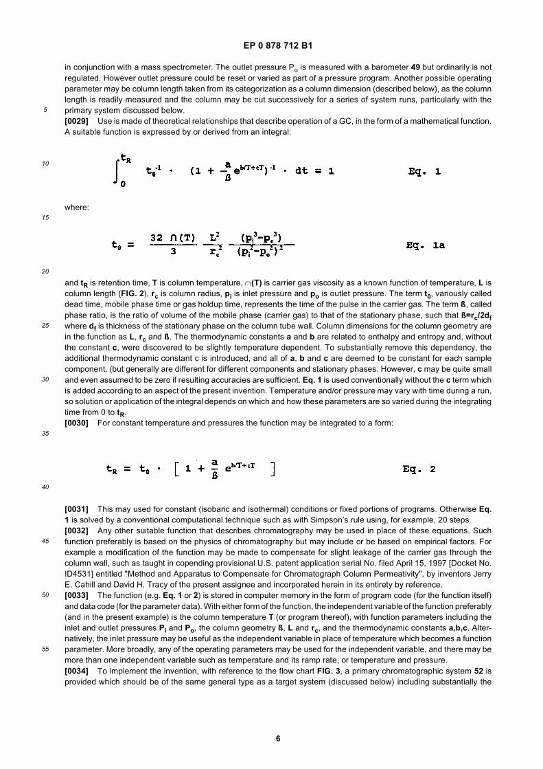
in conjunction with a mass spectrometer. The outlet pressure Po is measured with a barometer 49 but ordinarily is notregulated. However outlet pressure could be reset or varied as part of a pressure program. Another possible operatingparameter may be column length taken from its categorization as a column dimension (described below), as the columnlength is readily measured and the column may be cut successively for a series of system runs, particularly with theprimary system discussed below.[0029] Use is made of theoretical relationships that describe operation of a GC, in the form of a mathematical function.A suitable function is expressed by or derived from an integral:
where:
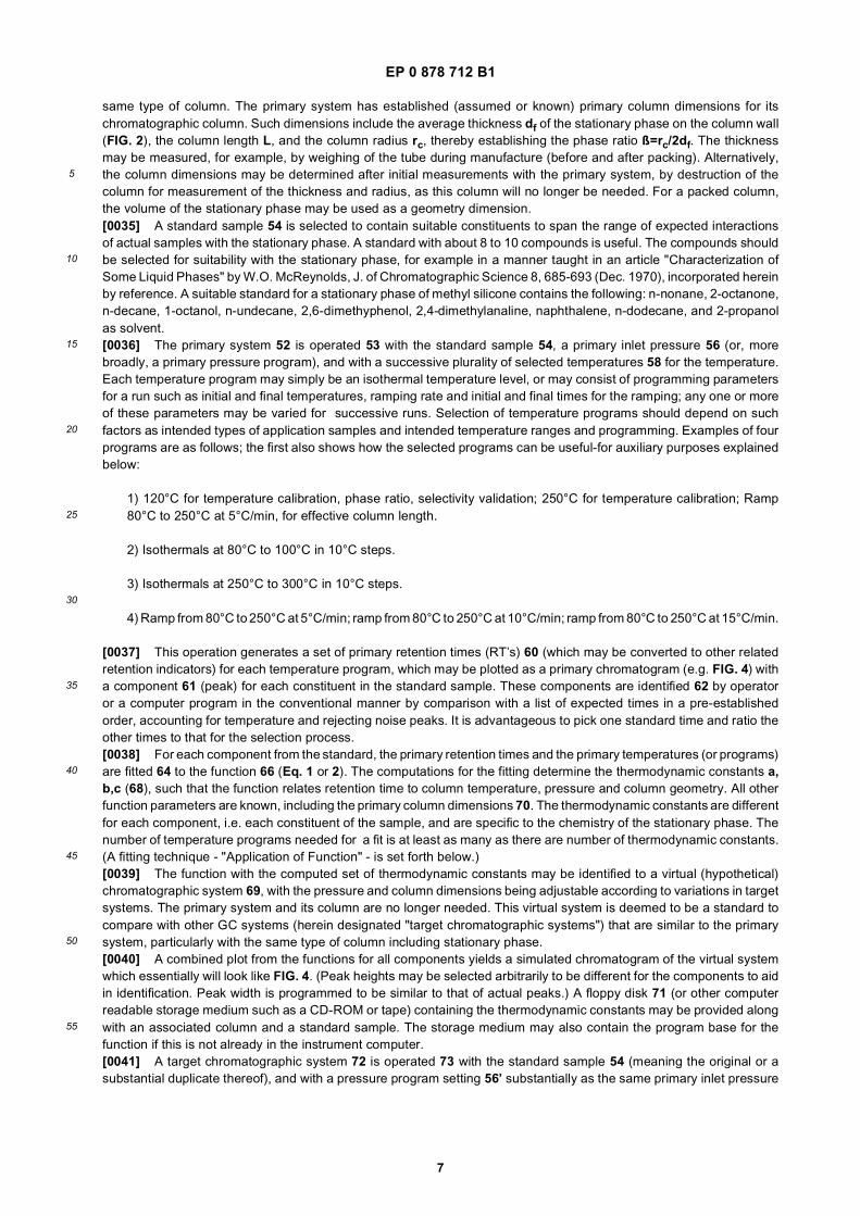
and tR is retention time, T is column temperature, ∩(T) is carrier gas viscosity as a known function of temperature, L iscolumn length (FIG. 2), rc is column radius, pi is inlet pressure and po is outlet pressure. The term t0, variously calleddead time, mobile phase time or gas holdup time, represents the time of the pulse in the carrier gas. The term ß, calledphase ratio, is the ratio of volume of the mobile phase (carrier gas) to that of the stationary phase, such that ß=rc/2dfwhere df is thickness of the stationary phase on the column tube wall. Column dimensions for the column geometry arein the function as L, rc and ß. The thermodynamic constants a and b are related to enthalpy and entropy and, withoutthe constant c, were discovered to be slightly temperature dependent. To substantially remove this dependency, theadditional thermodynamic constant c is introduced, and all of a, b and c are deemed to be constant for each samplecomponent, (but generally are different for different components and stationary phases. However, c may be quite smalland even assumed to be zero if resulting accuracies are sufficient. Eq. 1 is used conventionally without the c term whichis added according to an aspect of the present invention. Temperature and/or pressure may vary with time during a run,so solution or application of the integral depends on which and how these parameters are so varied during the integratingtime from 0 to tR.[0030] For constant temperature and pressures the function may be integrated to a form:
[0031] This may used for constant (isobaric and isothermal) conditions or fixed portions of programs. Otherwise Eq.1 is solved by a conventional computational technique such as with Simpson’s rule using, for example, 20 steps.[0032] Any other suitable function that describes chromatography may be used in place of these equations. Suchfunction preferably is based on the physics of chromatography but may include or be based on empirical factors. Forexample a modification of the function may be made to compensate for slight leakage of the carrier gas through thecolumn wall, such as taught in copending provisional U.S. patent application serial No. filed April 15, 1997 [Docket No.ID4531] entitled "Method and Apparatus to Compensate for Chromatograph Column Permeativity", by inventors JerryE. Cahill and David H. Tracy of the present assignee and incorporated herein in its entirety by reference.[0033] The function (e.g. Eq. 1 or 2) is stored in computer memory in the form of program code (for the function itself)and data code (for the parameter data). With either form of the function, the independent variable of the function preferably(and in the present example) is the column temperature T (or program thereof), with function parameters including theinlet and outlet pressures Pi and Po, the column geometry ß, L and rc, and the thermodynamic constants a,b,c. Alter-natively, the inlet pressure may be useful as the independent variable in place of temperature which becomes a functionparameter. More broadly, any of the operating parameters may be used for the independent variable, and there may bemore than one independent variable such as temperature and its ramp rate, or temperature and pressure.[0034] To implement the invention, with reference to the flow chart FIG. 3, a primary chromatographic system 52 isprovided which should be of the same general type as a target system (discussed below) including substantially the
EP 0 878 712 B1
7
5
10
15
20
25
30
35
40
45
50
55
same type of column. The primary system has established (assumed or known) primary column dimensions for itschromatographic column. Such dimensions include the average thickness df of the stationary phase on the column wall(FIG. 2), the column length L, and the column radius rc, thereby establishing the phase ratio ß=rc/2df. The thicknessmay be measured, for example, by weighing of the tube during manufacture (before and after packing). Alternatively,the column dimensions may be determined after initial measurements with the primary system, by destruction of thecolumn for measurement of the thickness and radius, as this column will no longer be needed. For a packed column,the volume of the stationary phase may be used as a geometry dimension.[0035] A standard sample 54 is selected to contain suitable constituents to span the range of expected interactionsof actual samples with the stationary phase. A standard with about 8 to 10 compounds is useful. The compounds shouldbe selected for suitability with the stationary phase, for example in a manner taught in an article "Characterization ofSome Liquid Phases" by W.O. McReynolds, J. of Chromatographic Science 8, 685-693 (Dec. 1970), incorporated hereinby reference. A suitable standard for a stationary phase of methyl silicone contains the following: n-nonane, 2-octanone,n-decane, 1-octanol, n-undecane, 2,6-dimethyphenol, 2,4-dimethylanaline, naphthalene, n-dodecane, and 2-propanolas solvent.[0036] The primary system 52 is operated 53 with the standard sample 54, a primary inlet pressure 56 (or, morebroadly, a primary pressure program), and with a successive plurality of selected temperatures 58 for the temperature.Each temperature program may simply be an isothermal temperature level, or may consist of programming parametersfor a run such as initial and final temperatures, ramping rate and initial and final times for the ramping; any one or moreof these parameters may be varied for successive runs. Selection of temperature programs should depend on suchfactors as intended types of application samples and intended temperature ranges and programming. Examples of fourprograms are as follows; the first also shows how the selected programs can be useful-for auxiliary purposes explainedbelow:
1) 120°C for temperature calibration, phase ratio, selectivity validation; 250°C for temperature calibration; Ramp80°C to 250°C at 5°C/min, for effective column length.
2) Isothermals at 80°C to 100°C in 10°C steps.
3) Isothermals at 250°C to 300°C in 10°C steps.
4) Ramp from 80°C to 250°C at 5°C/min; ramp from 80°C to 250°C at 10°C/min; ramp from 80°C to 250°C at 15°C/min.
[0037] This operation generates a set of primary retention times (RT’s) 60 (which may be converted to other relatedretention indicators) for each temperature program, which may be plotted as a primary chromatogram (e.g. FIG. 4) witha component 61 (peak) for each constituent in the standard sample. These components are identified 62 by operatoror a computer program in the conventional manner by comparison with a list of expected times in a pre-establishedorder, accounting for temperature and rejecting noise peaks. It is advantageous to pick one standard time and ratio theother times to that for the selection process.[0038] For each component from the standard, the primary retention times and the primary temperatures (or programs)are fitted 64 to the function 66 (Eq. 1 or 2). The computations for the fitting determine the thermodynamic constants a,b,c (68), such that the function relates retention time to column temperature, pressure and column geometry. All otherfunction parameters are known, including the primary column dimensions 70. The thermodynamic constants are differentfor each component, i.e. each constituent of the sample, and are specific to the chemistry of the stationary phase. Thenumber of temperature programs needed for a fit is at least as many as there are number of thermodynamic constants.(A fitting technique - "Application of Function" - is set forth below.)[0039] The function with the computed set of thermodynamic constants may be identified to a virtual (hypothetical)chromatographic system 69, with the pressure and column dimensions being adjustable according to variations in targetsystems. The primary system and its column are no longer needed. This virtual system is deemed to be a standard tocompare with other GC systems (herein designated "target chromatographic systems") that are similar to the primarysystem, particularly with the same type of column including stationary phase.[0040] A combined plot from the functions for all components yields a simulated chromatogram of the virtual systemwhich essentially will look like FIG. 4. (Peak heights may be selected arbitrarily to be different for the components to aidin identification. Peak width is programmed to be similar to that of actual peaks.) A floppy disk 71 (or other computerreadable storage medium such as a CD-ROM or tape) containing the thermodynamic constants may be provided alongwith an associated column and a standard sample. The storage medium may also contain the program base for thefunction if this is not already in the instrument computer.[0041] A target chromatographic system 72 is operated 73 with the standard sample 54 (meaning the original or asubstantial duplicate thereof), and with a pressure program setting 56’ substantially as the same primary inlet pressure
EP 0 878 712 B1
8
5
10
15
20
25
30
35
40
45
50
55
56 (or other pressure program); this pressure may not be quite the same as the primary due to variations in system andsettings. However a pressure calibration step is desirable for example by fully opening the flow valve 19 (FIG. 1) at thesplit flow exit and stopping carrier flow with the flow control 14 so as to expose the pressure gage to atmospheric pressureand use this as a zero calibration point 75 (gage pressure).[0042] A set of temperature values 74 is selected, which do not need to be the same as the primary temperatures.Suitable temperature programs are two fixed (isothermal) levels at 120°C and 250°C, and a ramping from 80°C to 250°Cat 5°C/minute. Corresponding secondary retention times 76 (or other retention indicators) are determined for the selectedtemperature programs. The isothermal retention times have several uses including standardization of systems, temper-ature calibration, validation and determination of phase ratio.[0043] The temperature scale of the target system should be calibrated 78 to effect calibrated temperatures 79, forexample in a manner described below using a secondary retention time for an isothermal for a specified component.Also, at this stage, a validation 80 of the target system (primarily to validate the stationary phase composition) is desirable,also as described below. If validation does not pass, further procedures are terminated to locate and fix 82 the problem,e.g. change columns.[0044] It is necessary to determine the parameters associated with column dimensions of the target system. Theremay be circumstances where the column dimensions for the target system are already established, e.g. in a prior runor by measurements during manufacture such as measuring the exact amount of stationary phase retained in the column.In this case the following procedure to determine column dimensions with the function may be skipped.[0045] The secondary retention times 76 are identified as target times for the function (Eq. 1 and/or 2). The targetsystem (particularly the target column) is characterized 84 by reverse application of the function 66, to determine effectivecolumn dimensions 86 for which a computation with the function yields substantially each secondary retention time forthe temperature at which the target system was run, using the previously determined thermodynamic constants 68 andthe primary inlet pressure 56. The phase ratio may be determined with the function; however, as explained below, thephase ratio ß advantageously is determined from retention times, so only a parameter associated with length L (viz. Litself or aspect ratio L/rc) needs to be determined with the function.[0046] Next, an effective secondary program for inlet pressure 88 is determined 90, again by reverse application ofEq. 1 and/or 2, for which, with the effective column dimensions 86 and the previously determined thermodynamicconstants 68, the function yields substantially the primary retention times 60 for any temperature program, preferablyone of the nominal selected temperature programs. A fixed pressure may be suitable, or a pressure program such asramping may be advantageous to achieve suitable equality of retention times. This secondary pressure program 88 maybe used 87 in subsequent system operations, or a selected program may be used by calibration.[0047] For such a selected pressure program, a fixed pressure for the program 88 also provides a second calibrationpoint for effective inlet pressure of the target system, compared to the pressure setting for the target system. With thispoint and the first calibration "zero" point 75 determined as described above, and with assumed linearity, a pressurecalibration 87 is established. Any operating pressure 89 (Pi, fixed or otherwise) may be selected for subsequent operationsof the target system. The proper pressure program setting corresponding to the operating pressure program is ascertainedfrom the calibration. Using the same procedures with other chromatographic systems operated for the same selected,calibrated pressure, retention times may be compared directly The actual pressure settings for the other systems wouldbe determined, calibrated and scaled in the same manner as in the present case.[0048] In the foregoing, an ideal goal is to determine the effective column dimensions and the secondary inlet pressuresuch that the function yields retention times exactly equal respectively to the secondary and primary retention times. Asthis generally is not quite attainable, the clarification "substantially" is intended to mean within practical limits of attain-ability. Details for application of the function are provided below.[0049] The target chromatographic system 72 then is operated 91 for sample analysis, using an application sample92 (usually unknown). For operating parameters, the selected pressure program 89, and any selected program (fixedor ramping) for the temperature 94 are used, preferably with temperature calibration 78. Such operation generates atleast one test retention time 96 for each component and each temperature program. By use of the secondary pressureprogram (fixed or ramping), the test retention times are thereby standardized to the virtual chromatographic system 69,and may be utilized for analysis 98 of the application sample. Similar operations with other application samples andother target systems provide retention times that, after normalization to a selected temperature by use of the function,may be compared directly. This also allows computer comparison and identification with a library of such times forselected chemical constituents.[0050] In the foregoing, temperature is selected conveniently as the independent variable with the pressure programas a parameter in the function. These roles could be reversed, with pressure as the independent variable. More broadly,any of the other operating parameters could be used in these roles, namely outlet pressure, ramping rates and times(or other program parameters), carrier gas composition (affecting viscosity ∩), column length, and even another columnparameter such as stationary phase composition or thickness if such can be varied controllably for a set of runs. Moreover,more than one of these variables could be used in each role at the same time, e.g. adding ramping to temperature. As
EP 0 878 712 B1
9
5
10
15
20
25
30
35
40
45
50
55
used herein and in the claims the term "first parameter" means the independent variable (temperature in the aboveexample), and "second parameter" means the parameter (e.g. inlet pressure) that is adjusted to standardize the targetsystem to the virtual system.[0051] As the function (Eq. 1 or 2) of the present embodiment includes inlet pressure, it is preferable that the systemutilize back pressure regulation of the split flow so that inlet pressure be controlled and known directly. However, theinvention could be utilized with flow regulation of the split flow such as disclosed in Hinshaw 1, provided inlet pressureto the column is measured and preferably is reproducible. Alternatively, with such a flow regulation system, a functionmay be derived with column flow rate as a first or second parameter in place of pressure, such flow rate being reproducibleand measured directly or ascertained by subtraction.[0052] The invention may be used with a supercritical fluid for the carrier. In this case the term "gas" herein includessuch fluid and the procedures are substantially the same as described herein including use of the same or other suitablefunction that describes the chromatography. The invention also may be utilized in a liquid chromatographic (LC) systemwith a liquid carrier such as the type described in the aforementioned U.S. patent No. 4,579,663. For LC additionalconsideration is given to interactions of the sample with the liquid carrier.
Column Dimensions
[0053] Characterizing 84 the effective column dimensions 86 (FIG. 3) for the target column conveniently has twoaspects. The phase ratio ß may be determined directly from a retention time. Other column dimensions are ascertainedas described below by application of the function.[0054] Phase ratio B=r/2d in the primary dimensions 70 for the primary column (ßp) preferably is determined fromactual measurements on the column, by destruction if necessary. Although the measurements should be as accurateas practical, absolute accuracy is not necessary because, in the characterization 84 for target column dimensions 86,the phase ratio for target columns (ßt) is determined relative to a known ßp. The phase ratio also has a relationshipß=K/k where k is a capacity factor and K is a partition coefficient that is constant for a given component, stationaryphase and temperature, so that ß is inversely proportional to k. The latter is calculated from k=(tR-to)/to where tR andto respectively are retention time and mobile phase time as defined above. The capacity factor k can be calculated fromany of the isothermal retention times taken with the primary and secondary system in the course of the other procedures.The phase ratio for the target column is related to that of the primary column by ßt=ßp·(kp/kt). This is used to computethe phase ratio for the column of each target system and is entered into the function prior to determination of the aspectratio. The latter is determined from the function as explained below.
Application of Function
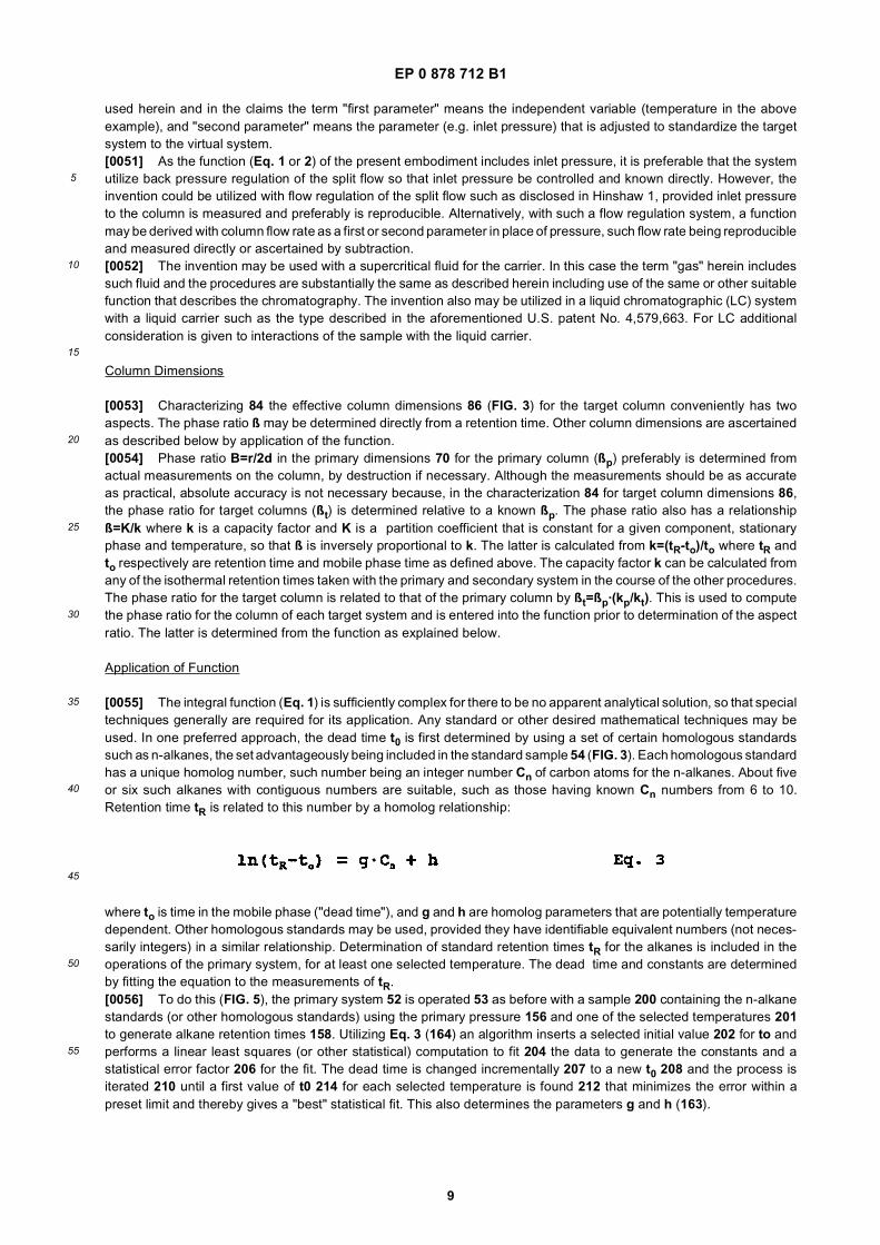
[0055] The integral function (Eq. 1) is sufficiently complex for there to be no apparent analytical solution, so that specialtechniques generally are required for its application. Any standard or other desired mathematical techniques may beused. In one preferred approach, the dead time t0 is first determined by using a set of certain homologous standardssuch as n-alkanes, the set advantageously being included in the standard sample 54 (FIG. 3). Each homologous standardhas a unique homolog number, such number being an integer number Cn of carbon atoms for the n-alkanes. About fiveor six such alkanes with contiguous numbers are suitable, such as those having known Cn numbers from 6 to 10.Retention time tR is related to this number by a homolog relationship:
where to is time in the mobile phase ("dead time"), and g and h are homolog parameters that are potentially temperaturedependent. Other homologous standards may be used, provided they have identifiable equivalent numbers (not neces-sarily integers) in a similar relationship. Determination of standard retention times tR for the alkanes is included in theoperations of the primary system, for at least one selected temperature. The dead time and constants are determinedby fitting the equation to the measurements of tR.[0056] To do this (FIG. 5), the primary system 52 is operated 53 as before with a sample 200 containing the n-alkanestandards (or other homologous standards) using the primary pressure 156 and one of the selected temperatures 201to generate alkane retention times 158. Utilizing Eq. 3 (164) an algorithm inserts a selected initial value 202 for to andperforms a linear least squares (or other statistical) computation to fit 204 the data to generate the constants and astatistical error factor 206 for the fit. The dead time is changed incrementally 207 to a new t0 208 and the process isiterated 210 until a first value of t0 214 for each selected temperature is found 212 that minimizes the error within apreset limit and thereby gives a "best" statistical fit. This also determines the parameters g and h (163).
EP 0 878 712 B1
10
5
10
15
20
25
30
35
40
45
50
55
[0057] As pressures are the same for the several isothermal operations, it may be seen from Eq. 1a that t0 is proportionalto carrier gas viscosity ∩(T) which is temperature dependent. A data base is stored 216 in the computer for the viscosityover the desired temperature range, conveniently in the form of parameters for a function relating viscosity to temperature.Values for other dead times t0 are obtained for the other relevant temperatures in proportion to the viscosities at theoriginal and the other temperatures to effect the temperature dependent t0(T). With these dead times, Eq. 1 is integrated(e.g. with Simpson’s method) over the three temperature programs for the standard compounds, to provide three equa-tions to solve 218 for the three thermodynamic constants a,b,c.[0058] For the dimensions 86 (FIG. 3) of the target column, the phase ratio ß is determined as explained above. Thecolumn length appears in Eqs. 1 and 2 via Eq. 1a as an aspect ratio α=L/rc. Thus either this ratio may be determinedas a length parameter, or rc may be estimated and an effective value for L determined (which corrects for any inaccuracyin rc). Conveniently the length L is taken to be the parameter.[0059] A searching technique may be used for solving the function to determine one or more parameters such as thelength L. A suitable technique (FIG. 6) for solving the function involves utilizing a stored initial parameter data base 102defining tentative values of the length (or other parameter) within a predetermined range over expected operatingconditions, such as from 20 m to 40 m in 1 m increments for a column having a nominal length of 30 m. (The data actuallystored may be the lowest and highest lengths plus increment value.) Other parameters 104 are known, namely thethermodynamic constants 68 (FIG. 3), set pressure 56, calibrated temperature 79 and phase ratio ß. With the function66 (e.g Eq. 1), theoretical retention times 106 are computed 108. Differences 110 ("errors" or "residuals") between thetheoretical times and measured times 76 are calculated 112. This is done for each value in the length base and for eachof the sample components, and is presented advantageously in the form of root-mean-square ("rms") residuals.[0060] The residuals may be plotted against the parameter if desired, or as contours if there are several parametersin the search, using conventional techniques. Such plot may be useful in visualizing a search, but is not important to thepresent invention.[0061] A search for the minimum may be done manually (e.g. by pointing and clicking an appropriate monitor displayof a plot of the residuals vs. length) or with any available or other desired computer program. An initial coarse search122 is advantageous, if not done previously 124, to find the region containing the lowest minimum. There may bemathematically forbidden areas in the range ("fractal space") which, if found, are assigned an arbitrarily high value suchas 1000. The minimum residual 120 then is determined. (Although not likely for the length L, in other applications forthe searching there may be several minima, and the coarse search should find the lowest.) A revised (narrowed) lengthdata base 126 with a smaller range such as 2 m around the minimum residual is selected 129, Eq. 1 is applied againto compute 108 theoretical retention times 106, and residuals 110 from the measured values 76 are recalculated 112.When a coarse search cycle 123 is determined 124 to have been done a set number of times (once should be sufficient),a fine search 128 is effected in the revised matrix 126 for the selected region so as to zero in on the minimum in theselected well. This may be done conventionally such as with linear programming, simulated annealing or, advantageously,an adaptive non-parametric search such as an algorithm for a downhill simplex method described in "Numerical Recipesin C" by W.H. Press, S.A. Teukolsky, W.T. Vetterling and B.P. Flannery, The Art of Scientific Computing, 2nd ed.,Cambridge University Press (1992). A conventional simplex search program determines the average of the residualsfor two proximate points that define a short line. The program flips the line over one of the points, redetermines theaverage and whether it has reduced; if not the line is flipped over to the other way. The procedure is repeated in searchof lower residuals 129. An advantageous modification to the simplex search shortens the point separations by a presetfactor when the residual average is reduced, or lengthens the separations by such a factor when a residual averageincreases, for example by a factor of two in each case. The starting points may the previously determined minimum andthe next best point.[0062] When a low residual 129 is found reflecting a "well", a test 130 for a nearly flat bottom of the well is made forthe rms residual not to change more than a preset limit such as 0.00001. If this is not met, the simplex cycle is repeated133 with a revised data base 126 of lengths selected 129 in smaller intervals around the latest region. If the number ofsimplex cycles exceeds a limit 134 such as 500 cycles, a problem is assumed to exist and the program is terminated136. Otherwise the last low residual is selected as the minimum 131 and this determines 137 the corresponding columnlength L or other parameter.[0063] A similar procedure may be used to apply the function with coarse and fine searching to determine 90 asecondary pressure program 88 (FIG. 3). If this is a fixed pressure, an initial data base of a range of potential pressuresis used for the initial parameter base 102 (FIG. 6) in place of the initial length base, the length L and radius rc replacethe initial pressure as predetermined parameters, and the measured retention times are the primary retention times.Otherwise the procedures of FIG. 6 are substantially the same. In the case of pressure or some other parameters, theremay be several minima from which the coarse search serves to select a lowest minimum before the simplex search.[0064] In the case of a pressure program with ramping, the procedures are effected with a matrix of parametersassociated with the program such as ramp rate and initial and final pressures (thus a 3-dimensional matrix). More broadly,the matrix has as many axes as variables being considered, e.g. one, two, three or more. Residuals are computed for
EP 0 878 712 B1
11
5
10
15
20
25
30
35
40
45
50
55
all of the compatible combinations in the matrix. For the coarse search, the residuals are searched by computer programto find the low in the same manner as described above. For a simplex search with a two-axis matrix, three proximatepoints are used in place of two for the averaging of residuals, and a triangle is visualized in place of the short connectingline. In the search the triangle is flipped over one of its sides for recomputation of an average. For a three-axis matrix,a pyramid is visualized with similar flips over an edge.[0065] The plotting and searching technique may be used for broader purposes, for example for an operator of achromatographic system to optimize selected operating parameters without necessarily being for the forgoing standard-ization to a virtual system. In the broader case, the system has operating parameters including selected parameters foroptimization and remaining parameters, and operation of the chromatographic system is represented by a mathematicalfunction having function parameters including the operating parameters. The primary chromatographic system is operatedwith a sample and selected values for the operating parameters so as to generate corresponding measured retentionindicators. A data set or matrix is provided comprising potential values of the selected operating parameters over pre-determined ranges of such parameters in predetermined increments, the data set representing combinations of suchparameters. Theoretical retention indicators are computed with the function for the combinations of such parametersand for the remaining parameters which are known or assumed for the purpose of the computation. Differences (residuals)between the measured retention indicators and the theoretical retention indicators are computed. The residuals aresearched for a minimum in the differences, such that the minimum establishes optimized selected parameters. Thesystem then is operated with the optimized parameters.[0066] It may be desirable for a plot of the retention times (actual and simulated) at each stage to be displayed on themonitor for operator viewing. Operator instructions for proceeding may be entered by way of pop up menus. Software(or firmware) with the function and the residual plotting and searching means for applying the function, along with matrixdata, may be incorporated into the computer programming of the system, or may be provided separately such as on afloppy disk.[0067] It is intended, as an aspect of this invention, that the foregoing searching technique may also be used directlyfor determining one or more optimum operating parameters for a chromatographic system, independently of any stand-ardizing.
Column Temperature
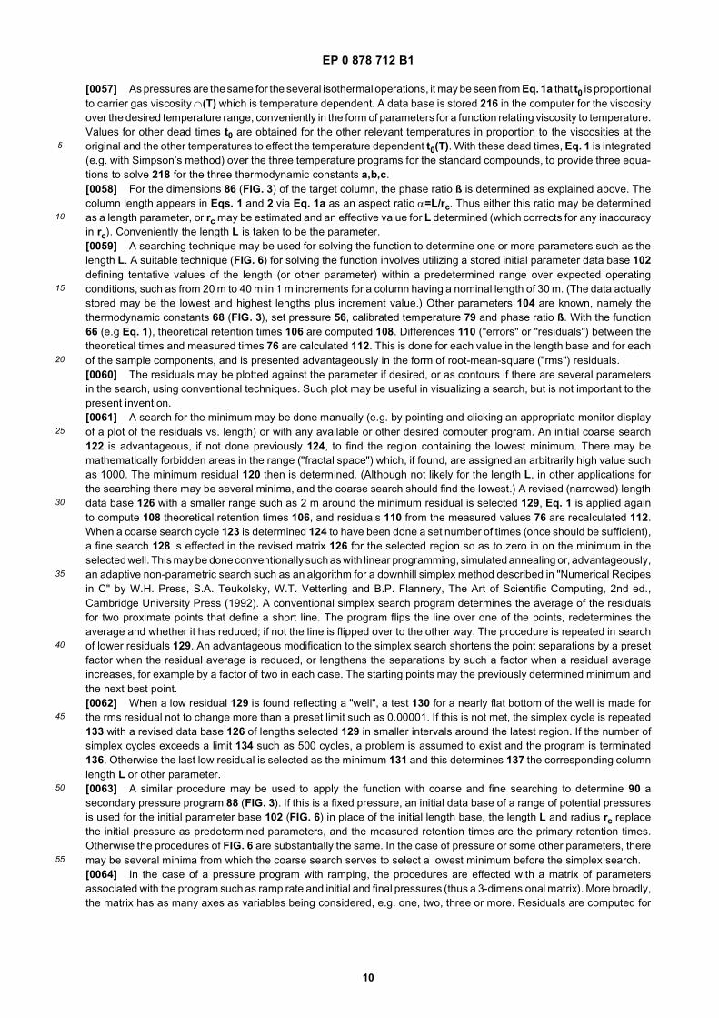
[0068] Temperatures for the primary chromatographic system should be measured as accurately as practical byconventional means, such as with several thermocouples distributed in the oven near the column and allowing the systemto stabilize at each temperature. Ultimately, however, the primary system temperatures may be considered to be standard,and absolute accuracy is not critical, as long as temperatures of subsequent system columns are accurate relative tothe original temperature scale of the primary.[0069] The operating temperatures of the target column should be determined with precision relative to the temperaturescale of the primary system. Calibration of temperature for the target column, according to an aspect of the invention,is made with use of a selected calibration compound. For this, it is advantageous to express the retention indicator inan alternate form "retention index" RI, also known as "Kovats Index", as for example in the following references: E.Kovats, Helv. Chim. Acta 41, 1915-1932 (1958); E. Kovats, Z. anal. Chem. 181, 351-366 (1961); P. Toth, E. Kugler, andE. Kovats, Helv. Chim. Acta 42, 2519-2530 (1959); A. Wehrli and E. Kovats, Helv. Chim. Acta 42, 2709-2736 (1959); L.S. Ettre, Anal. Chem. 36 (8), 31A-47A (1964); E. Kovats, in Advances in Chromatography Vol. 1 (J. C. Giddings and R.A. Keller, eds.), M. Dekker, Inc., New York, 1965; pp. 229-247. Retention index is defined as RI = 100·Cn, where Cn isa number associated with n-alkanes (or other standards) described above with respect to the homolog relationship Eq.3 which thereby becomes:
[0070] Any arbitrary compound (other than an n-alkane) has a retention index corresponding to a generally non-integerCn determined from Eq. 4 by measurement of retention time. The retention index for such a compound thus is relativeto the alkane standards, and is substantially independent of most parameters except temperature. This allows theretention index to be used in systems with varying parametric conditions while determining temperature dependence.To the extent that the retention index has a minor dependence on such parameters as pressure, such parameters shouldbe repeated as closely as practical for successive runs.[0071] For an aspect of the present invention, at least one temperature calibration compound is selected, the compoundpreferably having a retention index that has a relatively strong dependence on temperature. This compound is includedin a temperature standard sample with the several homologous standards (e.g. alkanes). To cover a desired temperature
EP 0 878 712 B1
12
5
10
15
20
25
30
35
40
45
50
55
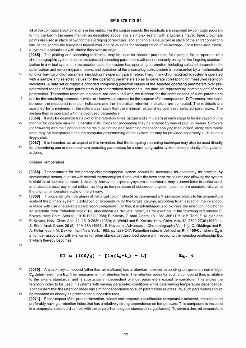
range it may be desirable to utilize two or more such compounds such as naphthalene and anthracene, each being mosteffective in a separate, narrower range for the temperature calibration, e.g. 120°C and 250°C respectively.[0072] Advantageously the temperature standard sample (with alkanes and calibration compounds) is included within the standard sample with the constituents used to define the virtual system, so only one set of runs is necessary, andtemperature is calibrated simultaneously with test operations. All or some of the calibration compounds and alkanesmay even be used for such constituents, except to define the virtual system it may be advantageous to use otherconstituents that have less temperature dependence. Moreover, such other constituents may better simulate the rangeof application sample materials likely to be tested.[0073] To establish temperatures, (FIG. 7), the primary chromatographic system 52 is operated 53 with the temperaturestandard 152 at a plurality of selected calibration temperatures 154 for the column and with a selected pressure program56. (For convenience these are included in the same conditions as for the standardizing runs, with the temperaturesused here being one of the isothermal runs. The number of temperatures depends on the number of constants in Eq.5 below, being three in the present case.) This generates a primary set of retention times for each temperature, comprisinghomolog (e.g. n-alkane) retention times 158 for each of the calibration compounds and a compound retention time 160for the temperature calibration compound. After peak identification (not shown) the homolog retention times and theknown retention indices Cn for the standards are used to determine 162 homolog parameters g and h (163) for theestablished relationship 164 (Eq. 3), relating homolog numbers to retention indicators (e.g. indices), these parametersbeing temperature dependent. A primary retention index 166 for the calibration compound is calculated 168 from therelationship 164 (Eq. 4) with the parameters g, h and the compound retention time 160 for the each calibration temper-ature, thereby relating a homolog number at each temperature for the calibration compound to its retention index. Theterm to in Eq. 4 is determined as described above. This homolog number is associated with the calibration temperatureTc (154). A temperature relationship 170 between retention index and temperature is close to being linear with temper-ature, but a quadratic fit may be used for accuracy:
where u, v and w are calibration constants 174 that are calculated 172 from the retention indices and temperature data.Several (three in the present case) primary temperature runs with different calibration temperatures are needed to getthese constants; again these may be combined with the original runs. These constants may be included in a data disk(or other such medium) along with the program base for Eq. 5 if necessary. Advantageously this is the disk that alsocontains the data base for the virtual system.[0074] The target chromatographic system then is operated 73 with the primary pressure program 56 and a selectedsecondary temperature 180 (or two such temperatures if two calibration standards are used), and with the sample 152,so as to generate a corresponding test set of retention times. The temperature 180 is measured with the scale (whichmay be arbitrary) associated with the target system. This operation is a temperature calibration run that for conveniencecould be the same as one of the runs for the standardization. These times comprise alkane retention times 182 and acompound retention time 184. The alkane retention times are used to redetermine 162 new homolog parameters g andh (188) for the established relationship (Eq. 3), and calculate 190 a secondary compound retention index 192 from therelationship 193 (Eq. 4) and the new parameters. The calibration relationship Eq. 5 (170, FIG. 7), with its earlier-determined constants 174, is applied with the calculated retention index 192 to determine 194 the calibrated columntemperature 79 for continuing with other procedures (FIG. 3), related to the primary system, that existed at the time ofoperation the target chromatographic system. If desired, a series of these temperatures may be determined to calibratethe temperature sensing system on the target system, so that the sensor may be used directly thereafter.[0075] Although retention index is a preferred form of retention indicator for the temperature calibration, as it simplifiesthe computations, other forms could be used. The retention indicator is advantageously in a form that is substantiallyindependent of system parameters and operating parameters other than temperature, the homologous standards eachhaving a predetermined retention indicator in such form. Also, the temperature calibration may be achieved with one ormore other homologous standards in place of the n-alkanes described above, provided such standards have a known,established relationship to their retention indicators.[0076] It is intended, as an aspect of this invention, that the foregoing technique for temperature calibration may alsobe used directly for calibrating a chromatographic system, independently of any standardizing.
Validation
[0077] It is desirable to validate the target system, to ensure particularly that the target column is of the type intendedand in satisfactory condition, and more particularly that the stationary phase chemistry ("selectivity") is satisfactory. Such
EP 0 878 712 B1
13
5
10
15
20
25
30
35
40
45
50
55
validation (80 in FIG. 3) may be effected with reference to FIG. 8. A validation sample 250 has a set of selected validationconstituents which may be included in the standard sample, and advantageously are the same as the constituents usedfor standardizing.[0078] Thus, as before, and conveniently during respective operations 53, 73 of standardizing runs with the primaryand target system 52, 72, the primary validation retention times 60 and the secondary validation retention times 76 areobtained and identified 62 for the validation sample constituents 250. The temperature programs 58, 74 each preferablyincludes an isothermal run (advantageously one of the original runs) with a primary validation temperature for the presentcase.[0079] Preliminary retention indices 252 are calculated 168 with Eq. 4 (193) (in the same manner as for the temperaturecalibration with reference to FIG. 7) and, similarly, secondary validation retention indices 258 are calculated 190. Theprimary indices are adjusted 254 to the secondary temperature 74 with Eq. 5 (170) to effect primary validation retentionindices 256.[0080] The differences 260 between the primary and secondary validation indices are calculated 262. The test forvalidation 80 is whether all of the differences are within predefined limits; if so, procedures are continued from thevalidation 80 with respect to FIG. 3 or, if not, the procedures are stopped to investigate and fix 82 the problem.[0081] It is intended, as an aspect of this invention, that the foregoing validation technique may also be used directlyfor validating a chromatographic system, independently of any standardizing.[0082] While the invention has been described above in detail with reference to specific embodiments, various changesand modifications which fall within the scope of the appended claims will become apparent to those skilled in this art.Therefore, the invention is intended only to be limited by the appended claims or their equivalents.
Claims
1. A method of standardizing a target chromatographic system with a primary chromatographic system, each systemincluding carrier means for passing a fluid carrier through the column, injection means for injecting a pulse of sampleinto the carrier to effect a mixture passing through the column subject to characteristic retention times for constituentsof the sample, detector means receptive of the mixture for effecting signals representative of the retention times,and processing means receptive of the signals for presenting corresponding retention indicators, wherein eachsystem has system parameters and operating parameters, the operating parameters comprising a first parameterhaving selectable first programming and a second parameter having selectable second programming, each pro-gramming being with respect to time, and the retention times being related to the system parameters and theoperating parameters by a mathematical function having function parameters including thermodynamic constantsassociated with interactions of the constituents with the column; the method comprising steps of:
establishing column dimensions of the primary chromatographic system;operating the primary chromatographic system with a standard sample, a selected primary second program forthe second parameter, and a plurality of selected primary first programs for the first parameter, so as to generatecorresponding primary retention indicators;fitting the primary retention indicators for each component of the standard sample and each selected primaryfirst programs to the function, with the primary second program, so as to determine thermodynamic constantswhereby the function is representative of a virtual chromatographic system; andstoring the thermodynamic constants for future application with the target chromatographic system.
2. The method of claim 1 wherein the retention indicators consist of retention times or retention indices.
3. The method of claim 1 wherein the first parameter is temperature of the column.
4. The method of claim 1 wherein each system is a gas chromatographic system, the fluid carrier is a gas carrier, andthe second parameter is inlet pressure of the carrier to the column.
5. The method of claim 1 wherein the system parameters comprise column dimensions.
6. The method of claim 1 further comprising:
initially operating a target chromatographic system with the standard sample, substantially the primary secondprogram, and a plurality of secondary first programs, so as to generate corresponding secondary retentionindicators;
EP 0 878 712 B1
14
5
10
15
20
25
30
35
40
45
50
55
establishing effective system parameters for the target chromatographic system;determining a secondary second program for which, with the effective system parameters,the function yields substantially the primary retention indicators for the primary first programs; andfurther operating the target chromatographic system with an application sample, the secondary second programand a selected first program, so as to generate at least one corresponding test retention indicator, wherebyeach test retention indicator is standardized to the virtual chromatographic system.
7. The method of claim 6 wherein the step of establishing effective system parameters comprises characterizing thetarget chromatographic system with effective system parameters for which the function yields substantially thesecondary retention indicators for the primary first programs and the primary second program.
8. The method of claim 7 wherein the system parameters comprise column dimensions, and the step of characterizingcomprises, for at least one specified column dimension, further steps of:
providing an initial data base defining a range of potential values of the specified column dimension;computing theoretical retention indicators with the function for the potential values, with the secondary temper-ature programs, the thermodynamic constants and the primary pressure program;computing differences between the theoretical retention indicators and the secondary retention indicators forthe secondary temperature programs; andsearching the differences for a minimum therein, such that the minimum establishes an effective value for thespecified column dimension.
9. The method of claim 8 wherein the step of searching comprises adaptive non-parametric searching.
10. The method of claim 9 wherein the step of searching further comprises, preceding the non-parametric searching,a further step of coarse searching to select a narrowed data base for the nonparametric searching.
11. The method of claim 6 wherein the step of determining comprises further steps of:
providing an initial data base defining a range of potential values of at least one parameter for a secondarysecond program;computing theoretical retention indicators with the function for the potential values, with the secondary firstprograms, the thermodynamic constants and the effective system parameters;computing differences between the theoretical retention indicators and the primary retention indicators; andsearching the differences for a minimum therein, such that the minimum establishes an effective value for theat least one parameter.
12. The method of claim 11 wherein the step of searching comprises adaptive non-parametric searching.
13. The method of claim 12 wherein the step of searching further comprises, preceding the non-parametric searching,a further step of coarse searching to select a narrowed data base for the nonparametric searching.
14. The method of claim 1 wherein each system includes a gas chromatographic column with associated columndimensions and a column inlet;said first parameter comprises a temperature and said selectable first programming comprises a temperature pro-gram; andsaid second parameter comprises a pressure and said selectable second programming comprises a pressureprogram;said mathematical function includes column dimensions;said method further comprising the step of: establishing primary column dimensions for the column of the primarychromatographic system.
15. The method of claim 14 wherein the retention indicators comprise retention times or retention indices.
16. The method of claim 14 wherein each temperature program consists of a fixed temperature or includes temperatureramping, and the pressure program consists of a fixed pressure or includes pressure ramping.
17. The method of claim 14 wherein the injector has a split flow with regulation of back pressure constituting the pressure
EP 0 878 712 B1
15
5
10
15
20
25
30
35
40
45
50
55
at the column inlet.
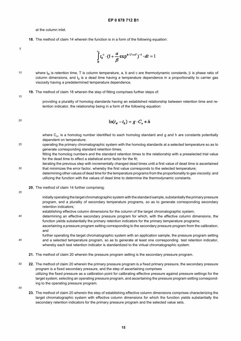
18. The method of claim 14 wherein the function is in a form of the following equation:
where tR is retention time, T is column temperature, a, b and c are thermodynamic constants, β is phase ratio ofcolumn dimensions, and t0 is a dead time having a temperature dependence in a proportionality to carrier gasviscosity having a predetermined temperature dependence.
19. The method of claim 18 wherein the step of fitting comprises further steps of:
providing a plurality of homolog standards having an established relationship between retention time and re-tention indicator, the relationship being in a form of the following equation:
where Cn, is a homolog number identified to each homolog standard and g and h are constants potentiallydependent on temperature;operating the primary chromatographic system with the homolog standards at a selected temperature so as togenerate corresponding standard retention times;fitting the homolog numbers and the standard retention times to the relationship with a preselected trial valuefor the dead time to effect a statistical error factor for the fit;iterating the previous step with incrementally changed dead times until a first value of dead time is ascertainedthat minimizes the error factor, whereby the first value corresponds to the selected temperature;determining other values of dead time for the temperature programs from the proportionality to gas viscosity; andutilizing the function with the values of dead time to determine the thermodynamic constants.
20. The method of claim 14 further comprising:
initially operating the target chromatographic system with the standard sample, substantially the primary pressureprogram, and a plurality of secondary temperature programs, so as to generate corresponding secondaryretention indicators;establishing effective column dimensions for the column of the target chromatographic system;determining an effective secondary pressure program for which, with the effective column dimensions, thefunction yields substantially the primary retention indicators for the primary temperature programs;ascertaining a pressure program setting corresponding to the secondary pressure program from the calibration;andfurther operating the target chromatographic system with an application sample, the pressure program settingand a selected temperature program, so as to generate at least one corresponding test retention indicator,whereby each test retention indicator is standardized to the virtual chromatographic system.
21. The method of claim 20 wherein the pressure program setting is the secondary pressure program.
22. The method of claim 20 wherein the primary pressure program is a fixed primary pressure, the secondary pressureprogram is a fixed secondary pressure, and the step of ascertaining comprisesutilizing the fixed pressure as a calibration point for calibrating effective pressure against pressure settings for thetarget system, selecting an operating pressure program, and ascertaining the pressure program setting correspond-ing to the operating pressure program.
23. The method of claim 20 wherein the step of establishing effective column dimensions comprises characterizing thetarget chromatographic system with effective column dimensions for which the function yields substantially thesecondary retention indicators for the primary pressure program and the selected value sets.
EP 0 878 712 B1
16
5
10
15
20
25
30
35
40
45
50
55
24. The method of claim 23 wherein the column comprises a stationary phase having an effective phase thickness, andthe column dimensions comprise the phase thickness, column length, and column radius.
25. The method of claim 24 wherein the step of characterizing comprises, for at least one specified column dimension,further steps of:
providing an initial data base defining a range of potential values of the specified column dimension;computing theoretical retention indicators with the function for the potential values, with the secondary temper-ature program, the thermodynamic constants and the primary pressure program;computing differences between the theoretical retention indicators and the secondary retention indicators forthe secondary temperature programs; andsearching the differences for a minimum therein, such that the minimum establishes an effective value for thespecified column dimension.
26. The method of claim 25 wherein the step of searching comprises adaptive non-parametric searching.
27. The method of claim 26 wherein the step of searching further comprises, preceding the non-parametric searching,a further step of coarse searching to select a narrowed data base for the nonparametric searching.
28. The method of claim 20 wherein the step of determining comprises further steps of:
providing an initial data base defining a range of potential values of at least one secondary pressure programparameter;computing theoretical retention indicators with the function for the potential values, with the secondary temper-ature program, the thermodynamic constants and the column dimension including the effective value for thespecified column dimension;computing differences between the theoretical retention indicators and the primary retention indicators; andsearching the differences for a minimum therein, such that the minimum establishes effective values for thesecondary pressure program parameters.
29. The method of claim 28 wherein the step of searching comprises adaptive non-parametric searching.
30. The method of claim 29 wherein the step of searching further comprises, preceding the non-parametric searching,a further step of coarse searching to select from potentially more than one minimum in the contour plot.
31. The method of claim 20 wherein, to determine column temperature of the target chromatographic system relativeto that of the primary chromatographic system, the method further comprises steps of:
providing a temperature standard comprising a calibration compound having temperature dependent retentiontime, and a plurality of homolog standards having a homolog relationship between corresponding retentionindicators and retention times;operating the primary chromatographic system with the temperature standard, a selected primary pressureprogram and a plurality of selected calibration temperatures so as to generate a primary set of retention tinesfor each calibration temperature, each primary set comprising homolog retention times for the homolog standardsand a compound retention time for the calibration compound;first utilizing the homolog relationship and the primary set of retention times for each calibration temperature todetermine calibration constants for a temperature relationship relating retention indicator for the calibrationcompound to column temperature for the primary system;operating the target chromatographic system with the temperature standard and a measured column temper-ature so as to generate a test set of retention times, the test set comprising test retention times for the homologstandards, and a test retention time for the calibration compound;second utilizing the homolog relationship and the test set of retention times to determine a secondary retentionindicator for the calibration compound; andapplying the temperature relationship with the calibration constants and the secondary retention indicator todetermine a calibrated temperature corresponding to the measured temperature.
32. The method of claim 31 wherein the retention indicator is in a form that is substantially independent of systemparameters and operating parameters other than temperature, the homolog standards each having a predetermined
EP 0 878 712 B1
17
5
10
15
20
25
30
35
40
45
50
55
retention indicator in such form.
33. The method of claim 32 wherein the retention indicator is retention index.
34. The method of claim 31 wherein:
the step of first utilizing comprises further steps of utilizing the standard retention times from the primary setsto determine primary homolog parameters for the homolog relationship,and calculating a primary retention indicator for the calibration compound from the homolog relationship, thecompound retention time and the primary homolog parameters for each calibration temperature, thereby relatingretention indicator for the calibration compound to column temperature for the primary system; andthe step of second utilizing comprises further steps of utilizing the test retention times from the test set toredetermine homolog parameters for the homolog relationship, and calculating the secondary retention indicatorfrom the homolog relationship, the redetermined homolog parameters and the measured retention time.
35. The method of claim 34 wherein, to validate the target chromatographic system, the method further comprises stepsof:
providing a validation sample comprising selected validation constituents;operating the primary chromatographic system with the validation sample, a selected primary pressure program,and a primary validation temperature, so as to generate corresponding primary validation retention times;utilizing the homolog relationship, the primary homolog parameters corresponding to the primary validationtemperature, and the primary retention times, to effect preliminary retention indicators;operating the target chromatographic system with the validation sample, substantially the primary pressureprogram, and the measured column temperature so as to generate corresponding secondary validation retentiontimes;utilizing the homolog relationship, the redetermined homolog parameters corresponding to the measured columntemperature, and the secondary validation retention times, to effect secondary validation retention indicators;adjusting the preliminary retention indicators, with the temperature relationship and corresponding primaryhomolog parameters to a calibrated temperature corresponding to the secondary validation temperature so asto effect primary validation retention indicators;calculating differences between corresponding primary validation retention indicators and secondary validationretention indicators; anddetermining whether the differences are less than a predetermined limit corresponding to whether the targetchromatographic system is valid.
36. The method of claim 35 wherein the retention indicator is in a form that is substantially independent of systemparameters and operating parameters other than temperature, the homolog standards each having a predeterminedretention indicator in such form.
37. The method of claim 36 wherein the retention indicator is retention index.
Patentansprüche
1. Verfahren zum Standardisieren eines chromatographischen Zielsystems mit einem primären chromatographischenSystem, wobei jedes System Trägermittel zum Leiten eines Fluidträgers durch die Säule aufweist, Injiziermittel zumInjizieren eines Probepulses in den Träger, um eine Mischung zu bewirken, die durch die Säule läuft, in Abhängigkeitvon charakteristischen Retentionszeiten für Bestandteile der Probe, Detektionsmittel, die die Mischung empfangen,um Signale zu erzeugen, die für die Retentionszeiten repräsentativ sind, und Verarbeitungsmittel, die die Signaleempfangen, um entsprechende Retentionsindikatoren zu präsentieren, wobei jedes System Systemparameter undBetriebsparameter hat, wobei die Betriebsparameter einen ersten Parameter aufweisen, der eine wählbare ersteProgrammierung hat, und einen zweiten Parameter, der eine wählbare zweite Programmierung hat, wobei jedeProgrammierung bezüglich der Zeit ist, und die Retentionszeiten mit den Systemparametern und den Betriebspa-rametern durch eine mathematische Funktion in Beziehung stehen, welche Funktionsparameter hat, die thermody-namische Konstanten aufweisen, die mit Wechselwirkungen der Bestandteile mit der Säule assoziiert sind;wobei das Verfahren die folgenden Schritte umfasst:
EP 0 878 712 B1
18
5
10
15
20
25
30
35
40
45
50
55
Erstellen von Säulendimensionen des primären chromatographischen Systems;Betreiben des primären chromatographischen Systems mit einer Standardprobe, einem ausgewählten primärenzweiten Programm für den zweiten Parameter, und einer Vielzahl ausgewählter primärer erster Programme fürden ersten Parameter, um entsprechende primäre Retentionsindikatoren zu erzeugen;Anpassen der primären Retentionsindikatoren für jede Komponente der Standardprobe und jedes ausgewählteprimäre erste Programm an die Funktion, mit dem primären zweiten Programm, um thermodynamische Kon-stanten zu bestimmen, wobei die Funktion für ein virtuelles chromatographisches System repräsentativ ist; undSpeichern der thermodynamischen Konstanten für zukünftige Anwendung mit dem chromatographischen Ziel-system.
2. Verfahren nach Anspruch 1, wobei die Retentionsindikatoren aus Retentionszeiten oder Retentionsindices bestehen.
3. Verfahren nach Anspruch 1, wobei der erste Parameter die Temperatur der Säule ist.
4. Verfahren nach Anspruch 1, wobei jedes System ein Gaschromatographie-System ist, der Fluidträger in Gasträgerist, und der zweite Parameter der Einlassdruck des Trägers in die Säule ist.
5. Verfahren nach Anspruch 1, wobei die Systemparameter Säulendimensionen aufweisen.
6. Verfahren nach Anspruch 1, das des Weiteren umfasst:
zunächst Betreiben eines chromatographischen Zielsystems mit der Standardprobe, im Wesentlichen demprimären zweiten Programm, und einer Vielzahl sekundärer erster Programme, um entsprechende sekundäreRetentionsindikatoren zu erzeugen;Erstellen effektiver Systemparameter für das chromatographische Zielsystem;Bestimmen eines sekundären zweiten Programms, für welches, mit den effektiven Systemparametern, dieFunktion im Wesentlichen die primären Retentionsindiaktoren für die primären ersten Programme ergibt; undweiterhin Betreiben des chromatographischen Zielsystems mit einer Anwendungsprobe, dem sekundären zwei-ten Programm und einem ausgewählten ersten Programm, um wenigstens einen entsprechenden Retentions-testindikator zu erzeugen, wobei jeder Retentionstestindikator auf das virtuelle chromatographische Systemstandardisiert wird.
7. Verfahren nach Anspruch 6, wobei der Schritt des Erstellens effektiver Systemparameter das Charakterisieren deschromatographischen Zielsystems mit effektiven Systemparametern umfasst, für welche die Funktion im Wesent-lichen die sekundären Retentionsindikatoren für die primären ersten Programme und das primäre zweite Programmergibt.
8. Verfahren nach Anspruch 7, wobei die Systemparameter Säulendimensionen aufweisen, und wobei der Schritt desCharakterisierens für wenigstens eine spezifizierte Säulendimension die folgenden weiteren Schritte umfasst:
Bereitstellen einer Anfangsdatenbank, die einen Bereich potentieller Werte der spezifizierten Säulendimensiondefiniert;Berechnen theoretischer Retentionsindikatoren mit der Funktion für die potentiellen Werte, mit den sekundärenTemperaturprogrammen, den thermodynamischen Konstanten und dem primären Druckprogramm;Berechnen der Differenzen zwischen den theoretischen Retentionsindikatoren und den sekundären Retenti-onsindikatoren für die sekundären Temperaturprogramme; undDurchsuchen der Differenzen nach einem Minimum, so dass das Minimum einen effektiven Wert für die spe-zifizierte Säulendimension liefert.
9. Verfahren nach Anspruch 8, wobei der Schritt des Durchsuchens adaptives nichtparametrisches Durchsuchenumfasst.
10. Verfahren nach Anspruch 9, wobei der Schritt des Durchsuchens, vor dem nichtparametrischen Durchsuchen, desWeiteren einen weiteren Schritt des groben Durchsuchens umfasst, um eine reduzierte Datenbank für das nicht-parametrische Durchsuchen auszuwählen.
11. Verfahren nach Anspruch 6, wobei der Schritt des Bestimmens die folgenden weiteren Schritte umfasst:
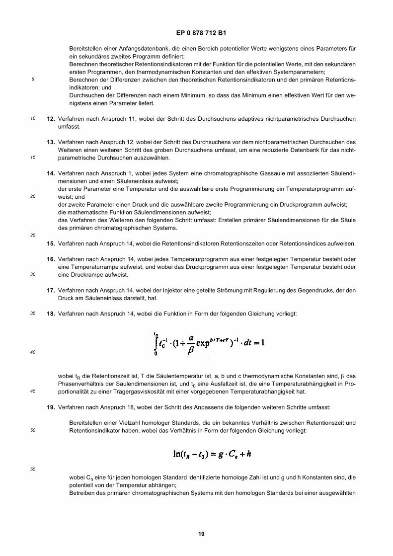
EP 0 878 712 B1
19
5
10
15
20
25
30
35
40
45
50
55
Bereitstellen einer Anfangsdatenbank, die einen Bereich potentieller Werte wenigstens eines Parameters fürein sekundäres zweites Programm definiert;Berechnen theoretischer Retentionsindikatoren mit der Funktion für die potentiellen Werte, mit den sekundärenersten Programmen, den thermodynamischen Konstanten und den effektiven Systemparametern;Berechnen der Differenzen zwischen den theoretischen Retentionsindikatoren und den primären Retentions-indikatoren; undDurchsuchen der Differenzen nach einem Minimum, so dass das Minimum einen effektiven Wert für den we-nigstens einen Parameter liefert.
12. Verfahren nach Anspruch 11, wobei der Schritt des Durchsuchens adaptives nichtparametrisches Durchsuchenumfasst.
13. Verfahren nach Anspruch 12, wobei der Schritt des Durchsuchens vor dem nichtparametrischen Durchsuchen desWeiteren einen weiteren Schritt des groben Durchsuchens umfasst, um eine reduzierte Datenbank für das nicht-parametrische Durchsuchen auszuwählen.
14. Verfahren nach Anspruch 1, wobei jedes System eine chromatographische Gassäule mit assoziierten Säulendi-mensionen und einen Säuleneinlass aufweist;der erste Parameter eine Temperatur und die auswählbare erste Programmierung ein Temperaturprogramm auf-weist; undder zweite Parameter einen Druck und die auswählbare zweite Programmierung ein Druckprogramm aufweist;die mathematische Funktion Säulendimensionen aufweist;das Verfahren des Weiteren den folgenden Schritt umfasst: Erstellen primärer Säulendimensionen für die Säuledes primären chromatographischen Systems.
15. Verfahren nach Anspruch 14, wobei die Retentionsindikatoren Retentionszeiten oder Retentionsindices aufweisen.
16. Verfahren nach Anspruch 14, wobei jedes Temperaturprogramm aus einer festgelegten Temperatur besteht odereine Temperaturrampe aufweist, und wobei das Druckprogramm aus einer festgelegten Temperatur besteht odereine Druckrampe aufweist.
17. Verfahren nach Anspruch 14, wobei der Injektor eine geteilte Strömung mit Regulierung des Gegendrucks, der denDruck am Säuleneinlass darstellt, hat.
18. Verfahren nach Anspruch 14, wobei die Funktion in Form der folgenden Gleichung vorliegt:
wobei tR die Retentionszeit ist, T die Säulentemperatur ist, a, b und c thermodynamische Konstanten sind, β dasPhasenverhältnis der Säulendimensionen ist, und t0 eine Ausfallzeit ist, die eine Temperaturabhängigkeit in Pro-portionalität zu einer Trägergasviskosität mit einer vorgegebenen Temperaturabhängigkeit hat.
19. Verfahren nach Anspruch 18, wobei der Schritt des Anpassens die folgenden weiteren Schritte umfasst:
Bereitstellen einer Vielzahl homologer Standards, die ein bekanntes Verhältnis zwischen Retentionszeit undRetentionsindikator haben, wobei das Verhältnis in Form der folgenden Gleichung vorliegt:
wobei Cn eine für jeden homologen Standard identifizierte homologe Zahl ist und g und h Konstanten sind, diepotentiell von der Temperatur abhängen;Betreiben des primären chromatographischen Systems mit den homologen Standards bei einer ausgewählten
EP 0 878 712 B1
20
5
10
15
20
25
30
35
40
45
50
55
Temperatur, um entsprechende Standard-Retentionszeiten zu erzeugen;Anpassen der homologen Zahlen und der Standard-Retentionszeiten an das Verhältnis mit einem vorgewähltenVersuchswert für die Ausfallzeit, um einen statistischen Fehlerfaktor für die Anpassung zu erzeugen;Wiederholen des vorhergehenden Schritts mit inkrementell geänderten Ausfallzeiten, bis ein erster Wert derAusfallzeit ermittelt wird, der den Fehlerfaktor minimiert, wobei der erste Wert der ausgewählten Temperaturentspricht;Bestimmen anderer Werte von Ausfallzeiten für die Temperaturprogramme aus der Proportionalität zur Gas-viskosität; undVerwenden der Funktion mit den Werten der Ausfallzeit, um die thermodynamischen Konstanten zu bestimmen.
20. Verfahren nach Anspruch 14, das des Weiteren umfasst:
zunächst Betreiben des chromatographischen Zielsystems mit der Standardprobe, im Wesentlichen dem pri-mären Druckprogramm, und einer Vielzahl sekundärer Temperaturprogramme, um entsprechende sekundäreRetentionsindikatoren zu erzeugen;Erstellen effektiver Säulendimensionen für die Säule des chromatographischen Zielsystems;Bestimmen eines effektiven sekundären Druckprogramms, für welches, mit den effektiven Säulendimensionen,die Funktion im Wesentlichen die primären Retentionsindiaktoren für die primären Temperaturprogramme ergibt;Ermitteln einer Druckprogrammeinstellung entsprechend dem sekundären Druckprogramm aus der Kalibrie-rung; undweiterhin Betreiben des chromatographischen Zielsystems mit einer Anwendungsprobe, der Druckprogramm-einstellung und einem ausgewählten Temperaturprogramm, um wenigstens einen entsprechenden Retentions-testindikator zu erzeugen, wobei jeder Retentionstestindikator auf das virtuelle chromatographische Systemstandardisiert wird.
21. Verfahren nach Anspruch 20, wobei die Druckprogrammeinstellung das sekundäre Druckprogramm ist.
22. Verfahren nach Anspruch 20, wobei das primäre Druckprogramm ein festgelegter primärer Druck ist, das sekundäreDruckprogramm ein festgelegter sekundärer Druck ist, und der Schritt des Ermittelns umfasst:
Verwenden des festgelegten Drucks als Kalibrierpunkt zum Kalibrieren effektiven Drucks gegenüber Druckein-stellungen für das Zielsystem, Auswählen eines Betriebsdruckprogramms und Ermitteln der Druckprogramm-einstellung entsprechend dem Betriebsdruckprogramm.
23. Verfahren nach Anspruch 20, wobei der Schritt des Erstellens effektiver Säulendimensionen das Charakterisierendes chromatographischen Zielsystems mit effektiven Säulendimensionen umfasst, für welche die Funktion im We-sentlichen die sekundären Retentionsindikatoren für das primäre Druckprogramm und die ausgewählten Wertsätzeergibt.
24. Verfahren nach Anspruch 23, wobei die Säule eine stationäre Phase aufweist, die eine effektive Phasenstärke hat,und wobei die Säulendimensionen die Phasenstärke, die Säulenlänge und den Säulenradius aufweisen.
25. Verfahren nach Anspruch 24, wobei der Schritt des Charakterisierens, für wenigstens eine spezifizierte Säulendi-mension, die folgenden weiteren Schritte umfasst:
Bereitstellen einer Anfangsdatenbank, die einen Bereich potentieller Werte der spezifizierten Säulendimensiondefiniert;Berechnen theoretischer Retentionsindikatoren mit der Funktion für die potentiellen Werte, mit dem sekundärenTemperaturprogramm, den thermodynamischen Konstanten und dem primären Druckprogramm;Berechnen der Differenzen zwischen den theoretischen Retentionsindikatoren und den sekundären Retenti-onsindikatoren für die sekundären Temperaturprogramme; undDurchsuchen der Differenzen nach einem Minimum, so dass das Minimum einen effektiven Wert für die spe-zifizierte Säulendimension liefert.
26. Verfahren nach Anspruch 25, wobei der Schritt des Durchsuchens adaptives nichtparametrisches Durchsuchenumfasst.
27. Verfahren nach Anspruch 26, wobei der Schritt des Durchsuchens vor dem nichtparametrischen Durchsuchen des
EP 0 878 712 B1
21
5
10
15
20
25
30
35
40
45
50
55
Weiteren einen weiteren Schritt des groben Durchsuchens umfasst, um eine reduzierte Datenbank für das nicht-parametrische Durchsuchen auszuwählen.
28. Verfahren nach Anspruch 20, wobei der Schritt des Bestimmens die folgenden weiteren Schritte umfasst:
Bereitstellen einer Anfangsdatenbank, die einen Bereich potentieller Werte wenigstens eines sekundären Druck-programmparameters definiert;Berechnen theoretischer Retentionsindikatoren mit der Funktion für die potentiellen Werte, mit dem sekundärenTemperaturprogramm, den thermodynamischen Konstanten und der Säulendimension einschließlich des ef-fektiven Werts für die spezifizierte Säulendimension;Berechnen der Differenzen zwischen den theoretischen Retentionsindikatoren und den primären Retentions-indikatoren; undDurchsuchen der Differenzen nach einem Minimum, so dass das Minimum effektive Werte für die sekundärenDruckprogrammparameter liefert.
29. Verfahren nach Anspruch 28, wobei der Schritt des Durchsuchens adaptives nichtparametrisches Durchsuchenumfasst.
30. Verfahren nach Anspruch 29, wobei der Schritt des Durchsuchens vor dem nichtparametrischen Durchsuchen desWeiteren einen weiteren Schritt des groben Durchsuchens umfasst, um aus potentiell mehr als einem Minimum imKonturdiagramm auszuwählen.
31. Verfahren nach Anspruch 20, wobei, um die Säulentemperatur des chromatographischen Zielsystems in Bezug zuder des primären chromatographischen Systems zu bestimmen, das Verfahren des Weiteren die folgenden Schritteumfasst:
Bereitstellen eines Temperaturstandards, der eine Kalibrierverbindung aufweist, die eine temperaturabhängigeRetentionszeit hat, und eine Vielzahl homologer Standards, die ein homologes Verhältnis zwischen entspre-chenden Retentionsindikatoren und Retentionszeiten haben;Betreiben des primären chromatographischen Systems mit dem Temperaturstandard, einem ausgewähltenprimären Druckprogramm und einer Vielzahl ausgewählter Kalibriertemperaturen, um einen primären Satz vonRetentionszeiten für jede Kalibriertemperatur zu erzeugen, wobei jeder primäre Satz homologe Retentionszeitenfür die homologen Standards und eine Verbindungs-Retentionszeit für die Kalibrierverbindung aufweist;erstes Verwenden des homologen Verhältnisses und des primären Satzes von Retentionszeiten für jede Kali-briertemperatur, um Kalibrierkonstanten für ein Temperaturverhältnis zu bestimmen, das Retentionsindikatorfür die Kalibrierverbindung mit Säulentemperatur für das primäre System ins Verhältnis setzt;Betreiben des chromatographischen Zielsystems mit dem Temperaturstandard und einer gemessenen Säu-lentemperatur, um einen Testsatz von Retentionszeiten zu erzeugen, wobei der Testsatz Testretentionszeitenfür die homologen Standards aufweist, und eine Testretentionszeit für die Kalibrierverbindung;zweites Verwenden des homologen Verhältnisses und des Testsatzes von Retentionszeiten, um einen sekun-dären Retentionsindikator für die Kalibrierverbindung zu bestimmen; undAnwenden des Temperaturverhältnisses mit den Kalibrierkonstanten und dem sekundären Retentionsindikator,um eine kalibrierte Temperatur entsprechend der gemessenen Temperatur zu bestimmen.
32. Verfahren nach Anspruch 31, wobei der Retentionsindikator in einer Form vorliegt, die im Wesentlichen von Sy-stemparametern und Betriebsparametern außer der Temperatur unabhängig ist, wobei die homologen Standardsjeweils einen vorgegebenen Retentionsindikator in einer solchen Form haben.
33. Verfahren nach Anspruch 32, wobei der Retentionsindikator ein Retentionsindex ist.
34. Verfahren nach Anspruch 31, wobei:
der Schritt des ersten Verwendens weitere Schritte des Verwendens der Standardretentionszeiten aus denprimären Sätzen umfasst, um primäre homologe Parameter für das homologe Verhältnis zu bestimmen, unddes Berechnens eines primären Retentionsindikators für die Kalibrierverbindung aus dem homologen Verhältnis,der Verbindungs-Retentionszeit und den primären homologen Parametern für jede Kalibriertemperatur, wobeiRetentionsindikator für die Kalibrierverbindung mit Säulentemperatur für das primäre System ins Verhältnisgesetzt wird; und
EP 0 878 712 B1
22
5
10
15
20
25
30
35
40
45
50
55
der Schritt des zweiten Verwendens weitere Schritte des Verwendens der Testretentionszeiten aus dem Testsatzumfasst, um homologe Parameter für das homologe Verhältnis neu zu bestimmen, und des Berechnens dessekundären Retentionsindikators aus dem homologen Verhältnis, den neu bestimmten homologen Parameternund der gemessenen Retentionszeit.
35. Verfahren nach Anspruch 34, wobei, um das chromatographische Zielsystem zu validieren, das Verfahren desWeiteren die folgenden Schritte umfasst:
Bereitstellen einer Validierungsprobe, die ausgewählte Validierungsbestandteile enthält;Betreiben des primären chromatographischen Systems mit der Validierungsprobe, einem ausgewählten primä-ren Druckprogramm und einer primären Validierungstemperatur, um entsprechende primäre Validierungsre-tentionszeiten zu erzeugen;Verwenden des homologen Verhältnisses, der primären homologen Parameter entsprechend der primärenValidierungstemperatur, und der primären Retentionszeiten, um vorläufige Retentionsindikatoren zu erzeugen;Betreiben des chromatographischen Zielsystems mit der Validierungsprobe, im Wesentlichen dem primärenDruckprogramm, und der gemessenen Säulentemperatur, um entsprechende sekundäre Validierungsretenti-onszeiten zu erzeugen;Verwenden des homologen Verhältnisses, der neu bestimmten homologen Parameter entsprechend der ge-messenen Säulentemperatur, und der sekundären Validierungsretentionszeiten, um sekundäre Validierungs-retentionsindikatoren zu erzeugen;Einstellen der vorläufigen Retentionsindikatoren mit dem Temperaturverhältnis und entsprechenden primärenhomologen Parametern auf eine kalibrierte Temperatur entsprechend der sekundären Validierungstemperatur,um primäre Validierungsretentionsindikatoren zu erzeugen;Berechnen der Differenzen zwischen entsprechenden primären Validierungsretentionsindikatoren und sekun-dären Validierungsretentionsindikatoren; undBestimmen, ob die Differenzen kleiner als eine vorgegebene Grenze sind, die der Gültigkeit des chromatogra-phischen Zielsystems entspricht.
36. Verfahren nach Anspruch 35, wobei der Retentionsindikator in einer Form vorliegt, die im Wesentlichen von Sy-stemparametern und Betriebsparametern außer der Temperatur unabhängig ist, wobei die homologen Standardsjeweils einen vorgegebenen Retentionsindikator in einer solchen Form haben.
37. Verfahren nach Anspruch 36, wobei der Retentionsindikator ein Retentionsindex ist.
Revendications
1. Procédé de standardisation d’un système chromatographique cible avec un système chromatographique principal,chaque système incluant un moyen de transport pour faire passer un porteur fluide à travers la colonne, un moyend’injection pour injecter une impulsion d’échantillon dans le porteur pour obtenir un mélange passant à travers lacolonne soumise à des temps de rétention caractéristiques pour des constituants de l’échantillon, un moyen détecteurrecevant le mélange pour obtenir des signaux représentatifs des temps de rétention, et un moyen de traitementrecevant les signaux pour présenter des indicateurs de rétention correspondants, dans lequel chaque système ades paramètres système et des paramètres de fonctionnement, les paramètres de fonctionnement comprenant unpremier paramètre ayant une première programmation sélectionnable et un deuxième paramètre ayant une deuxiè-me programmation sélectionnable, chaque programmation étant par rapport au temps, et les temps de rétentionétant liés aux paramètres système et aux paramètres de fonctionnement par une fonction mathématique ayant desparamètres de fonction incluant des constantes thermodynamiques associées avec des interactions des constituantsavec la colonne ; le procédé comprenant des étapes de :
établissement de dimensions de colonne du système chromatographique principal ;fonctionnement du système chromatographique principal avec un échantillon standard, un deuxième program-me principal sélectionné pour le deuxième paramètre, et une pluralité de premiers programmes principauxsélectionnés pour le premier paramètre, de façon à générer des indicateurs de rétention principauxcorrespondants ;ajustement des indicateurs de rétention principaux pour chaque composant de l’échantillon standard et chaquepremier programme principal sélectionné sur la fonction, avec le deuxième programme principal, de façon àdéterminer des constantes thermodynamiques, grâce à quoi la fonction est représentative d’un système chro-
EP 0 878 712 B1
23
5
10
15
20
25
30
35
40
45
50
55
matographique virtuel ; etstockage des constantes thermodynamiques pour application future avec le système chromatographique cible.
2. Procédé selon la revendication 1, dans lequel les indicateurs de rétention consistent en des temps de rétention oudes indices de rétention.
3. Procédé selon la revendication 1, dans lequel le premier paramètre est une température de la colonne.
4. Procédé selon la revendication 1, dans lequel chaque système est un système chromatographique en phase ga-zeuse, le porteur fluide est un porteur gazeux, et le deuxième paramètre est une pression d’entrée du porteur dansla colonne.
5. Procédé selon la revendication 1, dans lequel les paramètres système comprennent des dimensions de colonne.
6. Procédé selon la revendication 1, comprenant en outre :
le fonctionnement initial d’un système chromatographique cible avec l’échantillon standard, sensiblement ledeuxième programme principal, et une pluralité de premiers programmes secondaires, de façon à générer desindicateurs de rétention secondaires correspondants ;l’établissement de paramètres système effectifs pour le système chromatographique cible ;la détermination d’un deuxième programme secondaire pour lequel, avec les paramètres système effectifs, lafonction donne sensiblement les indicateurs de rétention principaux pour les premiers programmes principaux ;etle fonctionnement subséquent du système chromatographique cible avec un échantillon d’application, le deuxiè-me programme secondaire et un premier programme sélectionné, de façon à générer au moins un indicateurde rétention test correspondant, grâce à quoi chaque indicateur de rétention test est standardisé sur le systèmechromatographique virtuel.
7. Procédé selon la revendication 6, dans lequel l’étape d’établissement de paramètres système effectifs comprendla caractérisation du système chromatographique cible avec des paramètres système effectifs pour lesquels lafonction donne sensiblement les indicateurs de rétention secondaires pour les premiers programmes principaux etle deuxième programme principal.
8. Procédé selon la revendication 7, dans lequel les paramètres système comprennent des dimensions de colonne,et l’étape de caractérisation comprend, pour au moins une dimension de colonne spécifiée, des étapes additionnellesde :
prévision d’une base de données initiale définissant une plage de valeurs potentielles de la dimension decolonne spécifiée ;calcul d’indicateurs de rétention théoriques avec la fonction pour les valeurs potentielles, avec les programmesde température secondaires, les constantes thermodynamiques et le programme de pression principal ;calcul de différences entre les indicateurs de rétention théoriques et les indicateurs de rétention secondairespour les programmes de température secondaires ; etrecherche dans les différences d’un minimum de celles-ci, de sorte que le minimum établit une valeur effectivepour la dimension de colonne spécifiée.
9. Procédé selon la revendication 8, dans lequel l’étape de recherche comprend une recherche non paramétriqueadaptative.
10. Procédé selon la revendication 9, dans lequel l’étape de recherche comprend en outre, avant la recherche nonparamétrique, une étape additionnelle de recherche grossière pour sélectionner une base de données restreintepour la recherche non paramétrique.
11. Procédé selon la revendication 6, dans lequel l’étape de détermination comprend des étapes additionnelles de :
prévision d’une base de données initiale définissant une plage de valeurs potentielles d’au moins un paramètrepour un deuxième programme secondaire ;calcul d’indicateurs de rétention théoriques avec la fonction pour les valeurs potentielles, avec les premiers
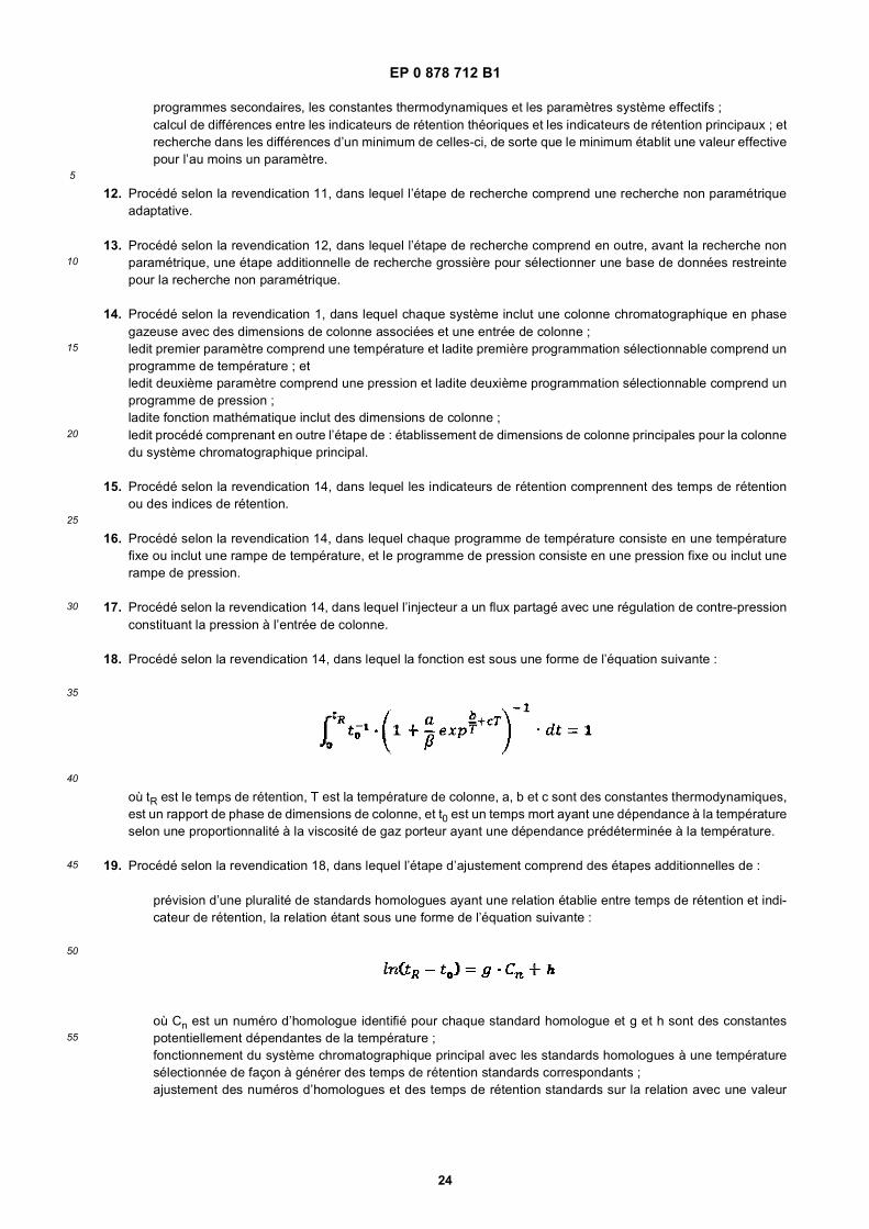
EP 0 878 712 B1
24
5
10
15
20
25
30
35
40
45
50
55
programmes secondaires, les constantes thermodynamiques et les paramètres système effectifs ;calcul de différences entre les indicateurs de rétention théoriques et les indicateurs de rétention principaux ; etrecherche dans les différences d’un minimum de celles-ci, de sorte que le minimum établit une valeur effectivepour l’au moins un paramètre.
12. Procédé selon la revendication 11, dans lequel l’étape de recherche comprend une recherche non paramétriqueadaptative.
13. Procédé selon la revendication 12, dans lequel l’étape de recherche comprend en outre, avant la recherche nonparamétrique, une étape additionnelle de recherche grossière pour sélectionner une base de données restreintepour la recherche non paramétrique.
14. Procédé selon la revendication 1, dans lequel chaque système inclut une colonne chromatographique en phasegazeuse avec des dimensions de colonne associées et une entrée de colonne ;ledit premier paramètre comprend une température et ladite première programmation sélectionnable comprend unprogramme de température ; etledit deuxième paramètre comprend une pression et ladite deuxième programmation sélectionnable comprend unprogramme de pression ;ladite fonction mathématique inclut des dimensions de colonne ;ledit procédé comprenant en outre l’étape de : établissement de dimensions de colonne principales pour la colonnedu système chromatographique principal.
15. Procédé selon la revendication 14, dans lequel les indicateurs de rétention comprennent des temps de rétentionou des indices de rétention.
16. Procédé selon la revendication 14, dans lequel chaque programme de température consiste en une températurefixe ou inclut une rampe de température, et le programme de pression consiste en une pression fixe ou inclut unerampe de pression.
17. Procédé selon la revendication 14, dans lequel l’injecteur a un flux partagé avec une régulation de contre-pressionconstituant la pression à l’entrée de colonne.
18. Procédé selon la revendication 14, dans lequel la fonction est sous une forme de l’équation suivante :
où tR est le temps de rétention, T est la température de colonne, a, b et c sont des constantes thermodynamiques,est un rapport de phase de dimensions de colonne, et t0 est un temps mort ayant une dépendance à la températureselon une proportionnalité à la viscosité de gaz porteur ayant une dépendance prédéterminée à la température.
19. Procédé selon la revendication 18, dans lequel l’étape d’ajustement comprend des étapes additionnelles de :
prévision d’une pluralité de standards homologues ayant une relation établie entre temps de rétention et indi-cateur de rétention, la relation étant sous une forme de l’équation suivante :
où Cn est un numéro d’homologue identifié pour chaque standard homologue et g et h sont des constantespotentiellement dépendantes de la température ;fonctionnement du système chromatographique principal avec les standards homologues à une températuresélectionnée de façon à générer des temps de rétention standards correspondants ;ajustement des numéros d’homologues et des temps de rétention standards sur la relation avec une valeur
EP 0 878 712 B1
25
5
10
15
20
25
30
35
40
45
50
55
d’essai présélectionnée pour le temps mort pour obtenir un facteur d’erreur statistique pour l’ajustement ;itération de l’étape précédente avec des temps morts changés de façon incrémentielle jusqu’à ce qu’une pre-mière valeur de temps mort soit constatée, qui minimise le facteur d’erreur, grâce à quoi la première valeurcorrespond à la température sélectionnée ;détermination d’autres valeurs de temps mort pour les programmes de température à partir de la proportionnalitéà la viscosité de gaz ; etutilisation de la fonction avec les valeurs de temps mort pour déterminer les constantes thermodynamiques.
20. Procédé selon la revendication 14, comprenant en outre :
le fonctionnement initial du système chromatographique cible avec l’échantillon standard, sensiblement le pro-gramme de pression principal, et une pluralité de programmes de températures secondaires, de façon à générerdes indicateurs de rétention secondaires correspondants ;l’établissement de dimensions de colonne effectives pour la colonne du système chromatographique cible ;la détermination d’un programme de pression secondaire effectif pour lequel, avec les dimensions de colonneeffectives, la fonction donne sensiblement les indicateurs de rétention principaux pour les programmes detempérature principaux ;le constat d’un réglage de programme de pression correspondant au programme de pression secondaire àpartir de l’étalonnage ; etle fonctionnement additionnel du système chromatographique cible avec un échantillon d’application, le réglagede programme de pression et un programme de température sélectionné, de façon à générer au moins unindicateur de rétention test correspondant, grâce à quoi chaque indicateur de rétention test est standardisépour le système chromatographique virtuel.
21. Procédé selon la revendication 20, dans lequel le réglage de programme de pression est le programme de pressionsecondaire.
22. Procédé selon la revendication 20, dans lequel le programme de pression principal est une pression principale fixée,le programme de pression secondaire est une pression secondaire fixée, et l’étape de constat comprendl’utilisation de la pression fixée comme un point d’étalonnage pour étalonner une pression effective par rapport àdes réglages de pression pour le système cible, la sélection d’un programme de pression de fonctionnement, et leconstat du réglage de programme de pression correspondant au programme de pression de fonctionnement.
23. Procédé selon la revendication 20, dans lequel l’étape d’établissement de dimensions de colonne effectives com-prend la caractérisation du système chromatographique cible avec des dimensions de colonne effectives pourlesquelles la fonction donne sensiblement les indicateurs de rétention secondaires pour le programme de pressionprincipal et les réglages sélectionnés de valeurs.
24. Procédé selon la revendication 23, dans lequel la colonne comprend une phase stationnaire ayant une épaisseurde phase effective, et les dimensions de colonne comprennent l’épaisseur de phase, la longueur de colonne, et lerayon de colonne.
25. Procédé selon la revendication 24, dans lequel l’étape de caractérisation comprend, pour au moins une dimensionde colonne spécifiée, des étapes additionnelles de :
prévision d’une base de données initiale définissant une plage de valeurs potentielles de la dimension decolonne spécifiée ;calcul d’indicateurs de rétention théoriques avec la fonction pour les valeurs potentielles, avec les programmesde température secondaires, les constantes thermodynamiques et le programme de pression principal ;calcul de différences entre les indicateurs de rétention théoriques et les indicateurs de rétention secondairespour les programmes de température secondaires ; etrecherche dans les différences d’un minimum de celles-ci, de sorte que le minimum établit une valeur effectivepour la dimension de colonne spécifiée.
26. Procédé selon la revendication 25, dans lequel l’étape de recherche comprend une recherche non paramétriqueadaptative.
27. Procédé selon la revendication 26, dans lequel l’étape de recherche comprend en outre, avant la recherche non
EP 0 878 712 B1
26
5
10
15
20
25
30
35
40
45
50
55
paramétrique, une étape additionnelle de recherche grossière pour sélectionner une base de données restreintepour la recherche non paramétrique.
28. Procédé selon la revendication 20, dans lequel l’étape de détermination comprend des étapes additionnelles de :
prévision d’une base de données initiale définissant une plage de valeurs potentielles d’au moins un paramètrede programme de pression secondaire ;calcul d’indicateurs de rétention théoriques avec la fonction pour les valeurs potentielles, avec le programmede température secondaire, les constantes thermodynamiques et la dimension de colonne incluant la valeureffective pour la dimension de colonne spécifiée ;calcul de différences entre les indicateurs de rétention théoriques et les indicateurs de rétention principaux ; etrecherche dans les différences d’un minimum de celles-ci, de sorte que le minimum établit des valeurs effectivespour les paramètres de programme de pression secondaire.
29. Procédé selon la revendication 28, dans lequel l’étape de recherche comprend une recherche non paramétriqueadaptative.
30. Procédé selon la revendication 29, dans lequel l’étape de recherche comprend en outre, avant la recherche nonparamétrique, une étape additionnelle de recherche grossière pour sélectionner à partir de potentiellement plusd’un minimum dans le tracé de contours.
31. Procédé selon la revendication 20, dans lequel, pour déterminer la température de colonne du système chromato-graphique cible par rapport à celle du système chromatographique principal, le procédé comprend en outre desétapes de :
prévision d’un standard de température comprenant un composé d’étalonnage ayant un temps de rétentiondépendant de la température, et d’une pluralité de standards homologues ayant une relation homologue entreindicateurs de rétention et temps de rétention correspondants ;fonctionnement du système chromatographique principal avec le standard de température, un programme depression principal sélectionné et une pluralité de températures d’étalonnage sélectionnées de façon à générerun ensemble principal de temps de rétention pour chaque température d’étalonnage, chaque ensemble principalcomprenant des temps de rétention homologues pour les standards homologues et un temps de rétention decomposé pour le composé d’étalonnage ;une première utilisation de la relation homologue et de l’ensemble principal de temps de rétention pour chaquetempérature d’étalonnage pour déterminer des constantes d’étalonnage pour une relation de température met-tant en rapport un indicateur de rétention pour le composé d’étalonnage et une température de colonne pourle système principal ;fonctionnement du système chromatographique cible avec le standard de température et une température decolonne mesurée de façon à générer un ensemble test de temps de rétention, l’ensemble test comprenant destemps de rétention tests pour les standards homologues, et un temps de rétention test pour le composéd’étalonnage ;une deuxième utilisation de la relation homologue et de l’ensemble test de temps de rétention pour déterminerun indicateur de rétention secondaire pour le composé d’étalonnage ; etapplication de la relation de température avec les constantes d’étalonnage et l’indicateur de rétention secondairepour déterminer une température étalonnée correspondant à la température mesurée.
32. Procédé selon la revendication 31, dans lequel l’indicateur de rétention est sous une forme qui est sensiblementindépendante de paramètres système et de paramètres de fonctionnement autres que la température, les standardshomologues ayant chacun un indicateur de rétention prédéterminé sous une telle forme.
33. Procédé selon la revendication 32, dans lequel l’indicateur de rétention est un indice de rétention.
34. Procédé selon la revendication 31, dans lequel :
l’étape de première utilisation comprend des étapes additionnelles d’utilisation des temps de rétention standardsprovenant des ensembles principaux pour déterminer des paramètres homologues principaux pour la relationhomologue, et de calcul d’un indicateur de rétention principal pour le composé d’étalonnage à partir de la relationhomologue, du temps de rétention de composé et des paramètres homologues principaux pour chaque tem-
EP 0 878 712 B1
27
5
10
15
20
25
30
35
40
45
50
55
pérature d’étalonnage, mettant ainsi en relation l’indicateur de rétention pour le composé d’étalonnage et latempérature de colonne pour le système principal ; etl’étape de deuxième utilisation comprend des étapes additionnelles d’utilisation des temps de rétention testsprovenant de l’ensemble test pour redéterminer des paramètres homologues pour la relation homologue, et decalcul de l’indicateur de rétention secondaire à partir de la relation homologue, des paramètres homologuesredéterminés et du temps de rétention mesuré.
35. Procédé selon la revendication 34, dans lequel, pour valider le système chromatographique cible, le procédé com-prend en outre des étapes de :
prévision d’un échantillon de validation comprenant des constituants de validation sélectionnés ;fonctionnement du système chromatographique principal avec l’échantillon de validation, un programme depression principal sélectionné, et une température de validation principale, de façon à générer des temps derétention de validation principaux correspondants ;utilisation de la relation homologue, des paramètres homologues principaux correspondant à la températurede validation principale, et des temps de rétention principaux, pour obtenir des indicateurs de rétentionpréliminaires ;fonctionnement du système chromatographique cible avec l’échantillon de validation, sensiblement le program-me de pression principal, et la température de colonne mesurée de façon à générer des temps de rétention devalidation secondaires correspondants ;utilisation de la relation homologue, des paramètres homologues redéterminés correspondant à la températurede colonne mesurée, et des temps de rétention de validation secondaires pour obtenir des indicateurs derétention de validation secondaires ;ajustement des indicateurs de rétention préliminaires, avec la relation de température et des paramètres ho-mologues principaux correspondants sur une température étalonnée correspondant à la température de vali-dation secondaire de façon à obtenir des indicateurs de rétention de validation principaux ;calcul de différences entre indicateurs de rétention de validation principaux et indicateurs de rétention de vali-dation secondaires ; etdétermination si les différences sont inférieures à une limite prédéterminée correspondant à la validité ou nondu système chromatographique cible.
36. Procédé selon la revendication 35, dans lequel l’indicateur de rétention est sous une forme qui est sensiblementindépendante de paramètres système et de paramètres de fonctionnement autres que la température, les standardshomologues ayant chacun un indicateur de rétention prédéterminé sous une telle forme.
37. Procédé selon la revendication 36, dans lequel l’indicateur de rétention est un indice de rétention.
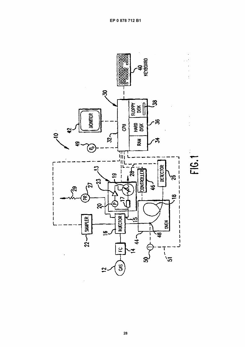
EP 0 878 712 B1
28
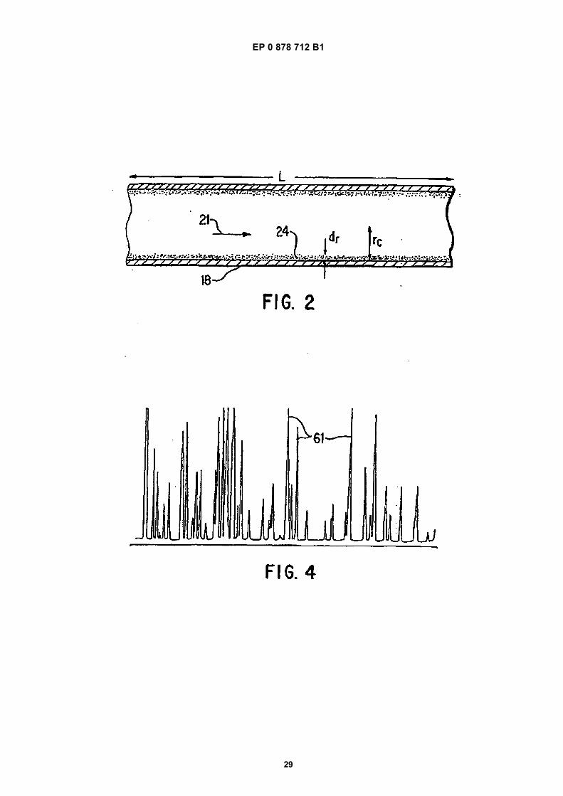
EP 0 878 712 B1
29
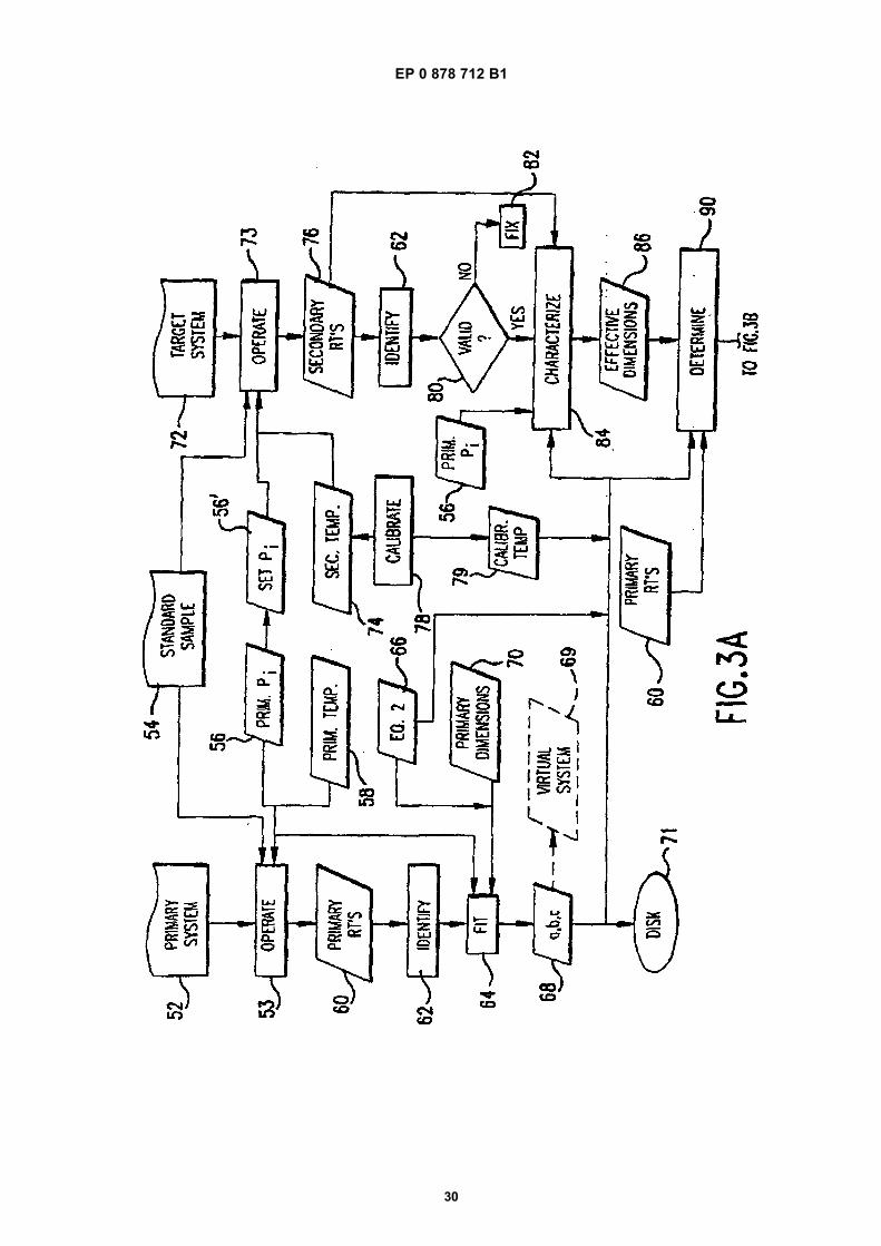
EP 0 878 712 B1
30
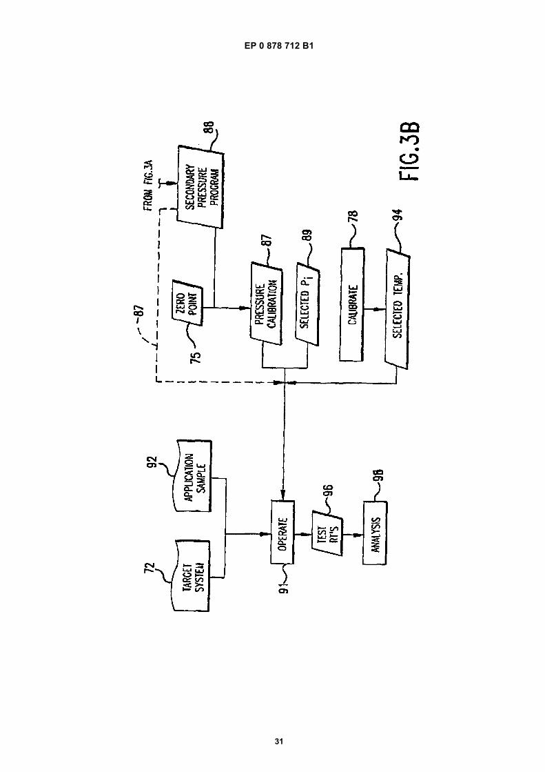
EP 0 878 712 B1
31
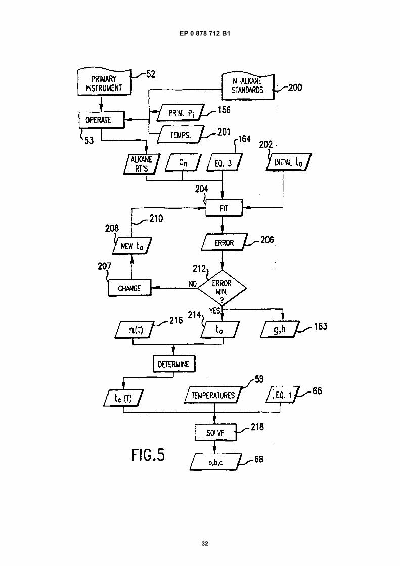
EP 0 878 712 B1
32
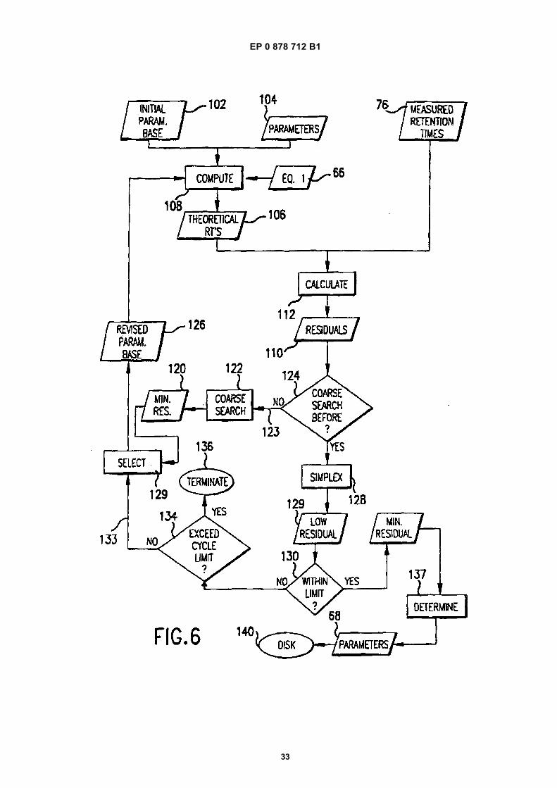
EP 0 878 712 B1
33
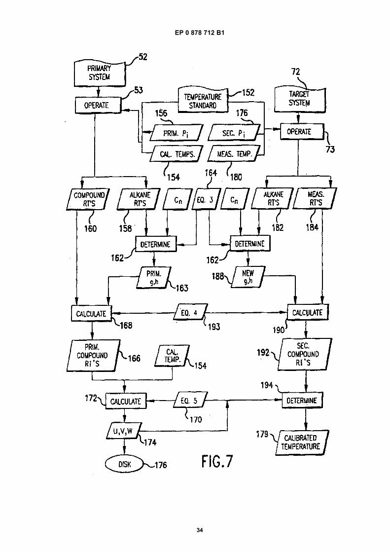
EP 0 878 712 B1
34
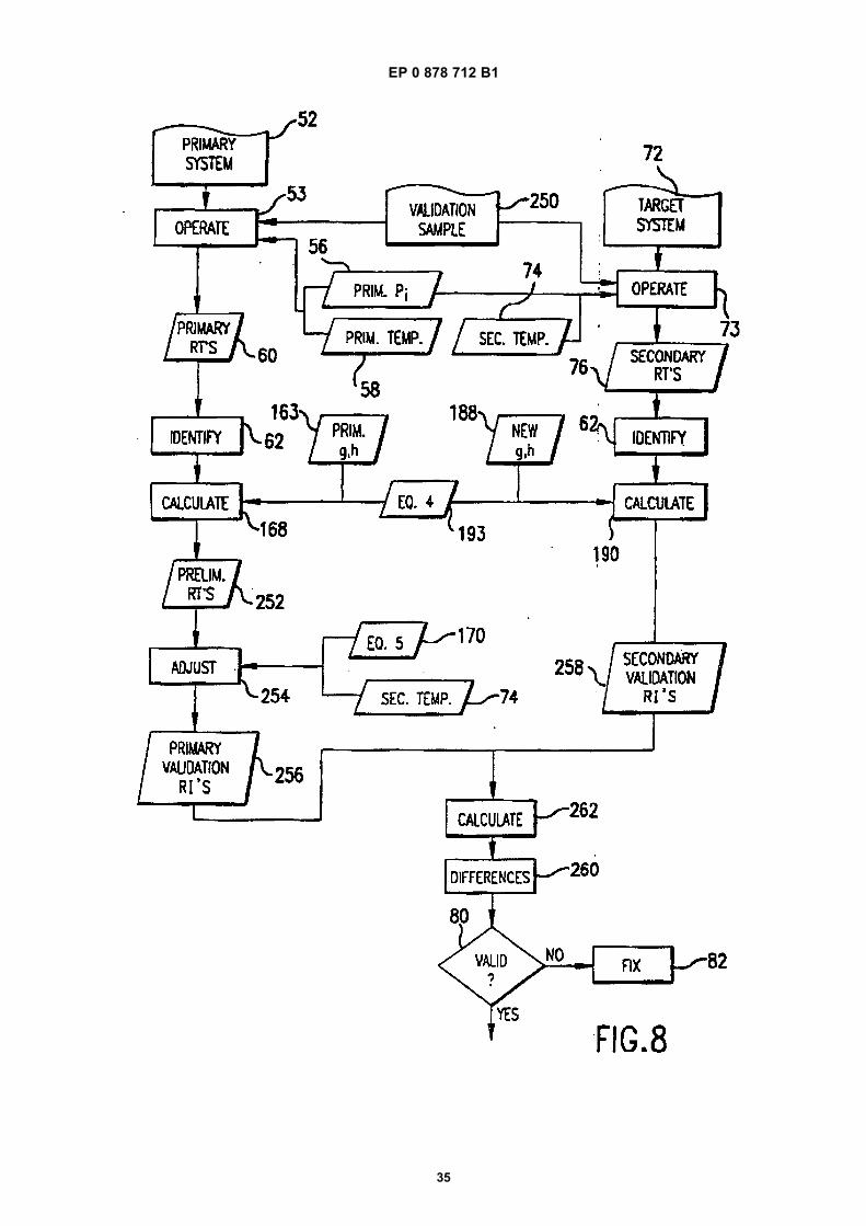
EP 0 878 712 B1
35
EP 0 878 712 B1
36
REFERENCES CITED IN THE DESCRIPTION
This list of references cited by the applicant is for the reader’s convenience only. It does not form part of the Europeanpatent document. Even though great care has been taken in compiling the references, errors or omissions cannot beexcluded and the EPO disclaims all liability in this regard.
Patent documents cited in the description
• US 5405432 A [0002] [0005]• US 5545252 A [0002] [0017]• US 73468996 A [0002]
• US 4579663 A [0002] [0052]• US 5303165 A, Ganz [0004]• US 734689 A, Hinshaw 2" [0017]
Non-patent literature cited in the description
• J.V. HINSHAW. The Effects of Inlet Liner Configura-tion and Septum Purge Flow Rate on Discriminationin Splitless Injection. J. High Resolution Chromatog-raphy, April 1993, vol. 16, 247-253 [0002]
• W.O. MCREYNOLDS. Characterization of Some Liq-uid Phases. J. of Chromatographic Science, Decem-ber 1970, vol. 8, 685-693 [0035]
• Numerical Recipes in C. W.H. PRESS ; S.A.TEUKOLSKY ; W.T. VETTERLING ; B.P. FLAN-NERY. The Art of Scientific Computing. CambridgeUniversity Press, 1992 [0061]
• E. KOVATS. Helv. Chim. Acta, 1958, vol. 41,1915-1932 [0069]
• E. KOVATS. Z. anal. Chem., 1961, vol. 181, 351-366[0069]
• P. TOTH ; E. KUGLER ; E. KOVATS. Helv. Chim.Acta, 1959, vol. 42, 2519-2530 [0069]
• A. WEHRLI ; E. KOVATS. Helv. Chim. Acta, 1959,vol. 42, 2709-2736 [0069]
• L. S. ETTRE. Anal. Chem., 1964, vol. 36 (8), 31A-47A[0069]
• E. KOVATS. Advances in Chromatography. M.Dekker, Inc, 1965, vol. 1, 229-247 [0069]