environmentally friendly drilling systems program · environmentally friendly drilling systems...
TRANSCRIPT

Environmentally Friendly Drilling Systems Program
Unbiased Data from an
Unbiased Source

EFD Team
Together
Everyone
Achieves
More
ENVIRONMENTAL ORGANIZATIONS
SPONSORS
Management Team
EFD Alliance
COLLABORATORS

EFD is the # 1 Program
in the Energy Industry Developing Innovative Environmental
Technology Rig Zone
Awards & Recognition
Best Health, Safety, Environment / Sustainable Development - Onshore AwardCleanSpacer™ III Spacer Fluid — HalliburtonElectro Water Separation (EWS) — OriginClearEnviroLift — Weatherford Inernational plcEnvironmentally Friendly Drilling Systems Program - Houston Advanced Research CenterModular Frac-flowback & Produced Water Treatment train technology — NSERC / ARIS-ET
Best Outreach ProgramAramco iExplore: Energy – AramcoEMSI High-Octane Tech Fest – WeatherfordEnvironmentally Friendly Drilling Virtual Site – Houston Advanced Research CenterGeoscientists Without Borders – Society of Exploration GeophysicistVeterans Resource Group – Baker Hughes Incorporated

Changing US Energy Mix

Production from Hydraulic Fracturing

New Record!Utica Shale

Colorado Energy

Piceance Basin
Top 20 in 2014
2014 ProductionOil Sales: 7,207,533 BblsGas Sales: 729,515,167 Mcf

Piceance Basin
Type Logs for Lower Williams Fork Formation in SE Piceance Basin
Stratigraphic cross section –distribution of deposits
Late Cretaceous Paleogeography showing extent of Western Interior Seaway during the Late Campanian and a depiction of the Late Cretaceous depositional environment in Utah/Colorado.
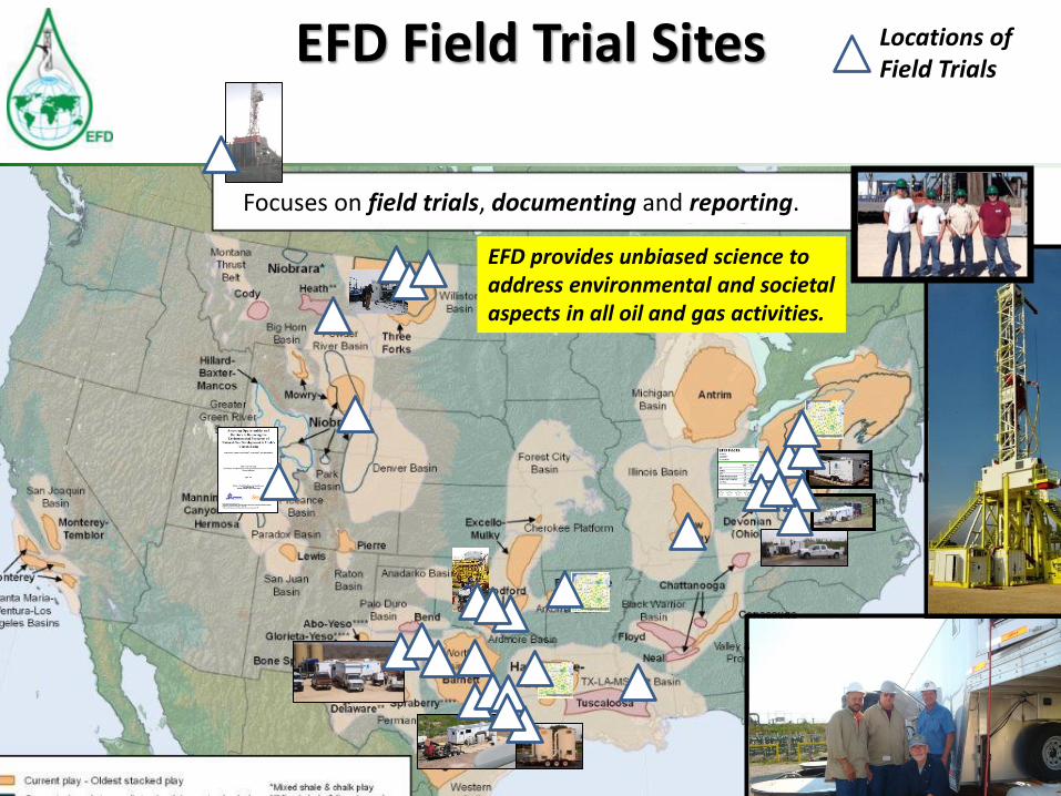
EFD Field Trial Sites
Focuses on field trials, documenting and reporting.
Locations of Field Trials
EFD provides unbiased science to address environmental and societal aspects in all oil and gas activities.
Environmental Risks

Approximately 8,000 feet
To Shale
Fresh Water Municipal Well
Less Than 1,000 feet
Multiple Layers of Casing and Cement
Intended to Isolate Drinking Water from
Completion and Production Fluids
In Modern Well Design Ground Water is Multiple Protected

Shale Gas Production and Theoretical
Possible Contamination Risks

MIT Study (2011) on Shale Gas Accidents in the US
Three studies combined - all reported US cases from 2000-2010 analyzed
Source 1 Source 2 Source 3
40,000+ shale gas wells drilled in the US during this period !

• Credible, transparent, understandable
• Withstands peer review
• Looks holistically at air, land, water and
biodiversity
• Maintains strong linkages to research
• Monitors regional stressors
• Takes advantage of local expertise
What does an Environmental
Monitoring System Look Like?

Monitoring Scope of Work
Data Reason Location Measurement Principle Method
Air Quality/ParticulateExhaust gases from operations, methane
from production, heavy traffic along
transport routes
Close to pads, close to surface
installation, along heavy traffic
transportation routes
Monitoring stations measure CO, NO2, O3, SO2, H2S,
methane, particulatesAutomated
Water Quality
Surface WaterContamination from spills during
drilling, production, transport, treatment
Close to pads, along transportation
routes, close to populated and
agricultural areas, in natural reserves,
at sewage plants
Sample containers, laboratory testing on chemistry,
total metals, organics, hydrocarbonManual
Ground WaterContamination from surface spills, bad
cementing, casing integrity, fracture
migration
Close to pads, close to agricultural and
populated areas, in natural reserves
Sample containers, laboratory testing on chemistry,
total metals, organics, hydrocarbonManual
Water Quantity
Surface Streams/Volumes Withdrawal for drilling & fracturing Rivers, streams, etc. Level/velocity Automated
Ground Water Level/StreamsWithdrawal may influence ground water
level
Close to pads, close to agricultural and
populated areas, in natural reserves
Level measurement, different stream flow
measurement methods availableManual
Soil Quality Deposition of contaminated material Close to padsSample containers, laboratory testing on physical,
chemical & biological contentManual
NoiseEngines required during drilling,
production, transportClose to populated areas Decibel meter Automated
Biodiversity General environmental impactsRivers, lakes, forests, agricultural
areas, natural reservesTaxonomic richness Manual
Seismic Waves Hydraulic fracturing, heavy transportClose to pads, close to other industry,
close to populated areasGeophones Automated
Tectonic Movements Production and re-injection Close to pads Optical level instrument Manual
Street Conditions Heavy Traffic Site access roads Visual, photographical Manual
Traffic Density Liquids and equipment transport Site access roads Video traffic detection Automated
Pipeline Integrity Corrosion, erosion Between check stations Pressure abnormalities Automated

Water Management – West TX
Assisted with development of water management strategies.

Emissions ?
Questions about Dual Fuel vs. Diesel Tail Pipe Emissions
○ NOx
○ CO
○ CH4 – Non-Combusted Methane (NCM) aka “Methane Slip”
○ NMHC – Non-Methane Hydrocarbon
○ CH2O – Formaldehyde (Carcinogen)
○ Soot – Main Component of Particulate Matter (PM)
Crankcase Emissions
Emission Control DeviceDiesel Oxidation Catalyst(DOC) Efficiency

D&C Ops: Field SetupInstruments / Sampling

Determined emission differences between hydraulic fracturing engines powered by diesel and engines powered with natural gas/diesel dual fuel.
Emissions from Hydraulic Fracturing Engines
• Natural gas dual fuel engine does not have clear advantages in emissions compared with diesel, further studies needed
• Un-combusted Methane is up to 30% of total natural gas fuel supply under high substitution rate, reduces fuel economy
• Further research is needed to address these issues – Have tested four different pump engines
45%65%
85%
1500 rpm 1600 rpm 1700 rpm 1800 rpm 1900 rpm 1950 rpm
45%65%
85%45%
65%85%
45%65%
85%45%
65%85%
Pump Load
Dual Fuel
Diesel
45%65%
85%
0
5000
10000
15000
20000
25000
30000
35000
40000
45000
50000
55000
60000
65000
Me
tha
ne
(C
H4
) [g
/hr]

Emissions from Hydraulic Fracturing Engines

Successfully developed and tested technology to capture VOC’s. System tested at CITGO Refinery.
• Currently testing at production stock tank.
Field Test – Emissions Control System
Removal Efficiency during field test period

Emission Characterization
• Open Path Fourier Transform Infrared Spectrometer, with integrated weather station in combination with a thermal imaging camera were used to collect emissions from an aging production facility.
• The facility known as “Central” was located in Dimmit County Texas on SHAPE ranch.

Emission Characterization
• Data was collected monthly from March – November 2015• 256 analytes were measured simultaneously during each sampling event• Approximately 50 analytes were detected and quantified above trace
SHAPE Ranch Sampling Team

Reducing Dust

Flaring Issues, Solutions, and Technologies (FIST)
Develop and Demonstrate Technologies to monetize stranded gas and to reduce or eliminate gas flaring and/or methane emissions associated with gas production.

Field Test – Flaring Mitigation
Objectives
Identify & test simple/robust technologies to reduce flaring
Location
• Field trials in the Bakken
Status• ORC equipment installed,
commissioned, operated. Field Trial Team
Technology identified through
assessment of RPSEA technologies.

Power From Produced Water(Previous RPSEA Funded Effort)

The ORC
• Recover Heat from Flare Gas • Use the heat to drive an Organic Rankine Cycle System • Use pressure of expanded working fluid to spin a generator

Provide Beneficial Use for Flare Gas
Gas Fueled Boiler
kW Output +
Reduced Flaring
X X

Field Test
• Test simple/robust ORC Technology to reduce flaring
• Demonstrate ability of the Power + to produce electricity from flare
• Demonstrate electricity production does not interfere with well operations
• Determine emissions offset and prove technology works
Trial Objectives
• 90 day pilot trial on the HA-ROLFSRUD site • July 29, 2015 to Nov 11, 2015• Emissions testing completed Oct 2015
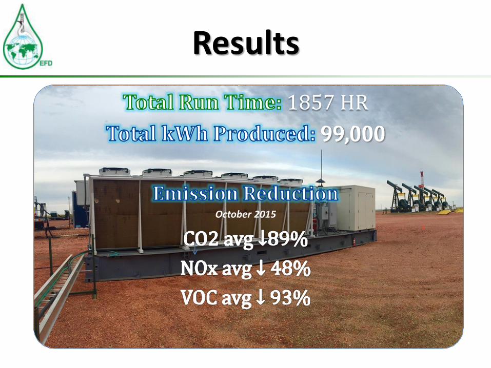
Results
1857 HR
October 2015

Summary• The trial has demonstrated that a beneficial use of flare gas is possible
• The system requires very little maintenance with approx. 1 man hour/week
• The Power+ system is an economical alternative to curtailing oil production due to flaring regulations
• Emissions can be reduced significantly

Development of LUSSIT• GIS based analytical tool that
aggregates spatially distributed attributes and considerations in the region(s) of interest to support site selection decisions.
• Tool beta tested in Sept/Oct 2015.• Tool now commercial!
Land Use Site Selection Information Tool LUSSIT
Tools for planning and evaluating infrastructure placement anyone can use
Simulate spill flow and termination scenarios
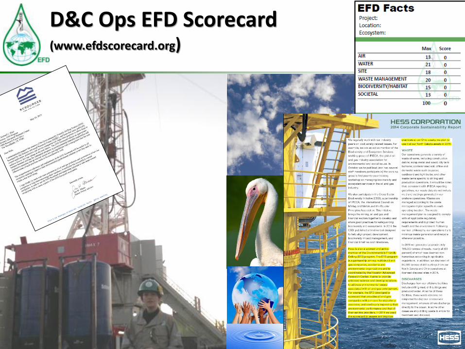
D&C Ops EFD Scorecard (www.efdscorecard.org)

Community Issues / Public Perception

1. Perception is a key factor in explaining:
a. attitudes toward, and
b. actions taken – either in support of or opposition to –
the development of oil and gas.
Selected Findings
2. Transparent communication between/ among all stakeholders is
paramount
a) Potentially positive aspects and negative consequences
b) Industry – share more information about shale gas
technologies with government and regulatory officials
and the general citizenry
3. Probability of risks exists
• Of rapid industrialization (boom and bust)
• Of uneven distribution of cost and benefit
• Of social-psychological stress

Environmental Friendly Drilling Rig

Technology Transfer
2016 -YTD
2015 2014 2013 2012
Publications 4 15 13 11 12
Presentations 10 57 48 24 32
Workshops 4 10 18 9 3
Webinars 2 5
Exhibits 1 2 4 1 12016July Nominated – Environmental Partnership Category, IOGCC Chairman’s Stewardship Awards
2015October Oil and Gas Awards – VZ Environmental Award for Excellence in Environmental Stewardship
October Finalist – Best Health, Safety, Environmental Program – Onshore, World Oil Awards
2014November Nominated – Protection of the Environment Prize, Eni Award
November Impact Award Nominee, 2014 Eagle Ford Excellence Awards, South Texas Energy Economic Roundtable
October Finalist – Best Outreach Program, World Oil Awards
August Nominated – Energy Education Category, IOGCC Chairman’s Stewardship Awards

Intermountain Oil & Gas Best
Management Practices
Projecthttp://www.oilandgasbmps.org

• Geographic Scope• CO, MT, NM, UT, WY• Beyond the Region
• Databases (searchable)• BMPs (>10,000)• Bibliography (> 800)• Laws and Regulations
(LawAtlas)• Website Background Materials
• Resource Pages• Law and Policy
(Federal, state, local, tribes)• Research Services• Workshops


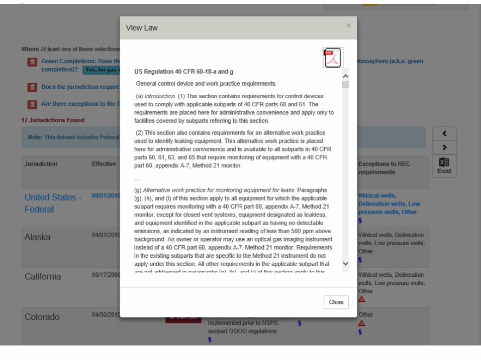
Comparative Law Database
• Water Quality – Lifecycle of field development
• Water Quantity –Administration, reporting, conservation, etc.
• Air Quality – Flares, engines, leak detection, storage, etc.
Current Database:
• States (17)• Federal
• BLM/BIA, USFS• EPA
• Local Jurisdictions (4)
2016 Expansion:• Setbacks• Induced Seismicity• Comparative analysis
factsheets


Browse the websites at:
www.oilandgasbmps.org and www.lawatlas.org/oilandgas
Contact Kathryn Mutz
Natural Resources LLC
303-499-1092
For more information

“Green” drilling is more than drilling
• Get in, drill and get out safely – as fast as possible with minimal disturbance to the land
• Protect surface and ground water
• Access roads
• Pad Drilling
• Reduce traffic, dust, noise, emissions, excessive lights that disturb nearby residences
• Aesthetics
• Flare/vapor recovery
• Gas captured to pipeline – flare gas only in necessary
• Pipe produced water/oil where feasible

It’s not so hard to be green
Questions?
Contact Rich:[email protected]
Thank you
www.efdsystems.orgwww.efdvirtualsite.orgwww.efdscorecard.orgwww.environment247.orgwww.oilandgasbmps.orgwww.lawatlas.org/oilandgaswww.facebook.com/EFDSystems