environmental pollution control alternatives: sludge ...infohouse.p2ric.org/ref/23/22206.pdf ·...
TRANSCRIPT
Technology Transfer EPA 625/5-82-018
Environmental Pollution Control Alternatives:
Sludge Handling, Dewatering, and Disposal Alternatives for the Metal Finishing Industry
October 1982
Technical content of this report was provided by the Industrial Environmental Research Laboratoiy Cincinnati OH 45268
This alternatives report was prepared by Centec Corporation of Reston VA for the Industrial Environmental Research Laboratory's Nonferrous Metals and Minerals Branch in Cincinnati OH. The EPA Project Officer IS
Alfred B. Craig, Jr.
EPA thanks the following companies and organizations for providing information and assistance: Barrett Centrifugals, Chemical Waste Manage- ment, Inc., Industrial Filter and Pump Manufacturing Company, Komline- Sanderson, Lenser America, Inc., SCA Services Company. and William R. Perrin Company.
Photographs were provided by Aqualogic' Inc.. Industrial Filter and Pump Manufacturing Company, Komline-Sanderson, and D. R. Sperry b Co.
The contact for further information is:
Nonferrous Metals and Minerals Branch Industrial Environmental Research Laboratory U.S. Environmental Protection Agency Cincinnati OH 45268
~~~~~ . ~ ~ ~ ~~ ~ ~ ~~ ~ ~ ~~ ~~~ ~ ~ ~
This report has been reviewed in accordance with the U.S. Environmental Protection Agency's peer and administrative review policies and approved for presentation and publication.
COVER PHOTOGRAPH: Recessed plate filter press with in-ground bin to receive discharged cake
ii
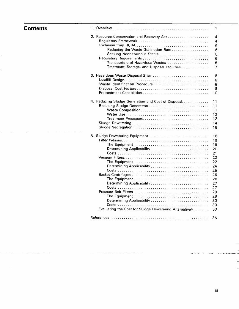
Contents 1. Overview . . . . . . . . . . . . . . . . . . . . . . . 1
2. Resource Conservation and Recoven/ Ac t . . . . . . . . . . . . . . . . . . . . 4 Regulatory Framework . . Exclusion from RCRA . . . . . . . . . . . . . .
Reducing the Waste Generation R Seeking Nonhazardous Status
Transporters of Hazardous Wastes . . . . . . . . . . . . . . . . . . . . Treatment, Storage, and Disposal Facilities . . . . . . . . . . . . .
Regulatow Requirements . . . . . . . . . . . . . . . 6 7
Landfill Design., . . . . . . . . . . . . . . . . . . . . Waste Identification Procedure . . . . . . . Disposal Cost Factors
4. Reducing Sludge Generation and Cost of Disposal., , ,
. . . . . . . . . 12
. . . . . . . . . 14
. . . . . . . . . 16
5. Sludge Dewatering Equipment . . . . . . . . . . . . . . . . Filter Presses. .
. . . . . . . . 22 The Equipment . . . . . . . . . . . . . . . . . . . . . . . . . . . . . 22 Determining Applicability, , , , , . . . . . . . . . . . 24
. . . , . . . . . . . . 25 . . . . . . . . . . . . .
. . . . . . . . . . . . . . . . . . . . . . . . . . . . .
costs . . . . . . . . . . Pressure Belt Filters . . . . . . . . . . . . . . . . . .
. . . . . . . . . . . . . . . . . . . . . . References. . . . . . . . . . . . 35
iii
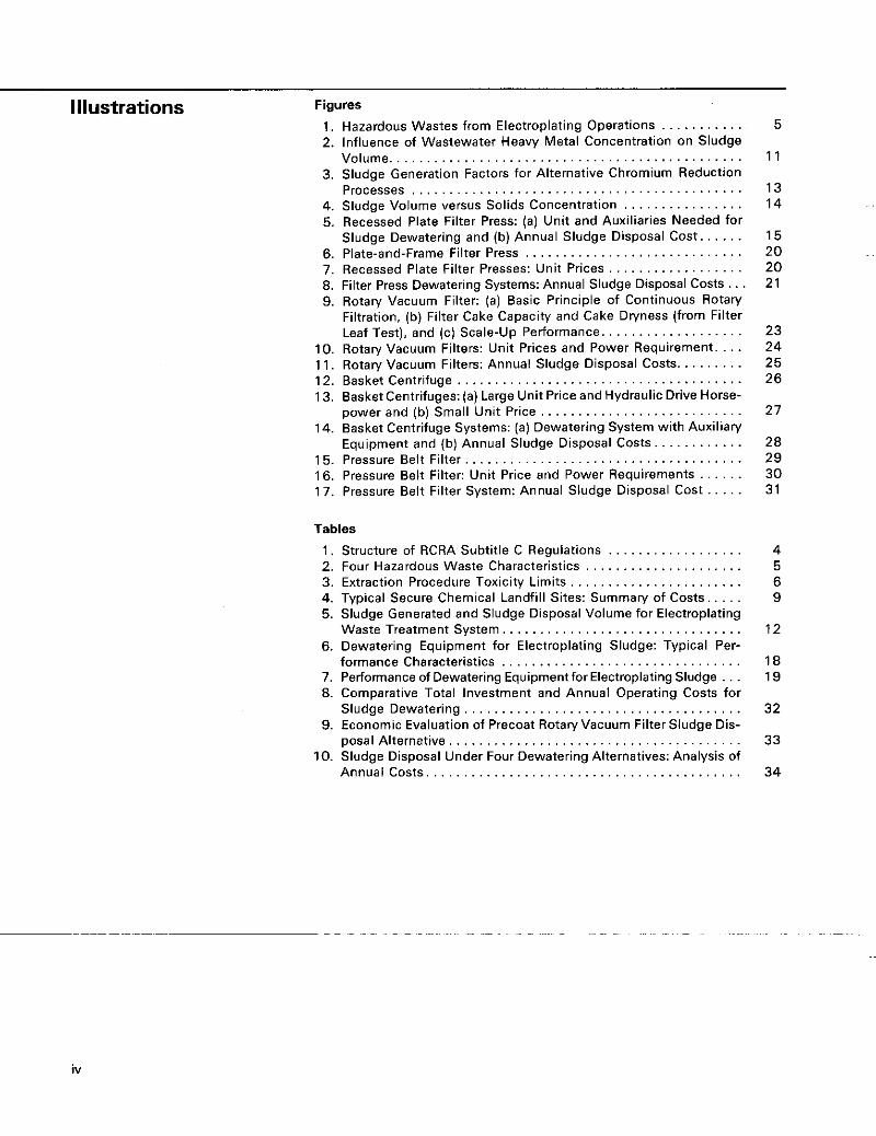
Illustrations Figures
1 , Hazardous Wastes from Electroplating Opera 2. Influence of Wastewater Heavy Metal Conce
for Alternative Ch . . . . . . . . . . . . . . . . . . . . . . . . . . . . .
Processes . . . . . . . . . . . . . . . . . . . . . . . . . . . . . . . . . . 4. Sludge Volume versus Solids Concentration . . . . . . . . . . . . . . . . 5. Recessed Plate Filter Press: (a) Unit and Auxiliaries Needed for
Sludge Dewatering and (b) Annual Sludge Disposal Cost. . . . . . 6. Plate-and-Frame Filter Press . . . 7. Recessed Plate Filter Presses: U . . . . . . . . . . . . 8. Filter Press Dewatering Systems: Annual Sludge Disposal Costs.. . 9. Rotary Vacuum Filter: (a) Basic Principle of Continuous Rotary
Filtration, (b) Filter Cake Capacity and Cake Dryness (from Filter Leaf Test), and (c) Scale-up Performance.. . . . . . . . . . .
IO. Rotary Vacuum Filters: Unit Prices and Power Requirement. . . . 1 1 . Rotary Vacuum Filters: Annual Sludge Disposal Costs. . . . . . . . . 13. Basket Centrifuges: (a) ulic Drive Horse-
14. Basket Centrifuge Systems: (a) Dewatering System with Auxiliary Equipment and (b) Annual Sludge Disposal Costs
15. Pressure Belt Filter.. . , , , , . . . . . . . . . . . . . . 16. Pressure Belt Filter: Unit Price and Power Requiremen s 17. Pressure Belt Filter System: Annual Sludge Disposal Cost
, , , , . . . . . . . . . .
12. Basket Centrifuge . . . . . . . . . . . . . . . . .
power and (b) Small Unit Price , , , , , . . . . . . . . .
Tables
1 , Structure of RCRA Subtitle C Regulations . . . . . . . . . . . . . . . . . . 2. Four Hazardous Waste Characteristics . . . . . . . . . . . . . . . . . . . . . 3. Extraction Procedure Toxicity Limits . . . , . . . . . . . . . . . . . . . . . . . 4. Typical Secure Chemical Landfill Sites: Summary of Costs. . . . . 5. Sludge Generated and Sludge Disposal Volume for Electroplating
Waste Treatment System.. . . . . . . . . . . . . . . . . . . . . . . . . . . . . . . 6. Dewatering Equipment for Electroplating Sludge: Typical Per-
formance Characteristics . . . . . . . 7. Performance of Dewatering Equipmentfor Electroplating Sludge . . . 8. Comparative Total Investment and Annual Operating Costs for
9. Economic Evaluation of Precoat Rotary Vacuum Filter Sludge Dis- posal Alternetive . . . . . . . . . . . . . . . . . . . . . . . . . . . . . . . . . . . . . . .
10. Sludge Disposal Under Four Dewatering Alternatives: Analysis of Annual Costs . . . . . . . . . . . . . . . . . . . . . . . . . . . . . . . . . . . . . . . . . .
Sludge Dewatering . . . . . . . . . . . . . . . . . . . . . . . . . . . . .
5
1 1
13 14
15 20 20 21
23 24 25 26
27
28 29 30 31
4 5 6 9
12
18 19
32
33
34
iv
1. Overview Under regulations implementing the Clean Water Act of 1977 (Public Law 95-21 7) metal finishing facil- ities may be required to treat spent process wastewaters to remove regulated pollutants before the wastewaters are discharged. Treatment for heavy metal pollutants generally consists of reducing the solubility of the metals, then separating the resulting precipitants from the wastewater. Consequently, the treatment yields a solid waste, or sludge, containing a high con- centration of potentially harm- ful or toxic substances. This sludge must be disposed of in a manner that ensures that the pollutants, once removed from the wastewater, will not pose a threat to the environment.
Recognizing the increased rate of solid waste generation and the need for environmentally safe disposal, the US. Congress included provisions for solid waste disposal in the Re- source Conservation and Recovery Act (RCRA) of 1976 (Public Law 94-580). Subtitle C of RCRA contains provisions for hazardous waste management. It directs the US. En- vironmental Protection Agency (EPA) to identify those wastes that are hazardous, and to establish national standardsfor generators and transporters of hazardous wastes and for operators of hazardous waste management facilities involved in the treatment, storage, and dis- posal of these wastes.
The EPA has classified the following metal finishing wastes as hazard- ous materials:’
Plating baths and the sludge accumulated in these baths Stripping and cleaning solutions Sludge resulting from wastewater
Metal finishing shops disposing af-any~of these~wastes are regulated by the RCRA standards. Under RCRA. EPA holds waste generators responsible for the ultimate safe disposal of their wastes. Waste gen- erators are also required to keep
treatment
records, use proper labels and containers, and keep a manifest sys- tem to document proper disposal.
The more stringent control of hazardous waste disposal means that plating shops may have difficulty in finding licensed disposal facili- ties. and may incur higher prices for hauling and disposal than if their wastes were nonhazardous.
Hauling costs depend on the distance to the disposal site and the size of the load. Haulers typically use trucks designed for loads of 40,000 Ib (1 8,000 kg), Or5.000 gal (1 9,000 L); they can transport liquids or solids. A partial load would be charged the same price as a full load. Prices for long hauls are in the order of $3 to $5 per loaded mile for the 5,000-gal (1 9.000-L) load, based on the distance one way.a A 300-mi (480-km) trip, therefore, would cost $0.18/gal to $0.30/gal of waste, assuming the truck had a full load. Because there are so few dis- posal sites, long-distance hauling is becoming the rule, not the exception.
Disposal facilities operating state- of-the-art secure chemical landfills charge according to volume, type of waste, and type of container. Disposal of drum quantities is by far the most expensive. Fees at disposal sites range from $25 to $50 for each drum that requires burial in the site. The equivalent cost per gallon would be $0.60 to $1.20, based on 42-gal (1 59-L) drum capac- iv. Adding drum and hauling costs could bring the total disposal cost to $1 00 per drum.
Bulk liquids, which include dilute sludges and spent process baths, are less expensive to dispose of than drum quantities; however, the disposal cost includes the cost for solidifying the waste before it is placed in thalandfill site. Costs range from $0.25/gal to $0.75/gal.
‘All costs in this repon are in 1581 ddhrs.
1
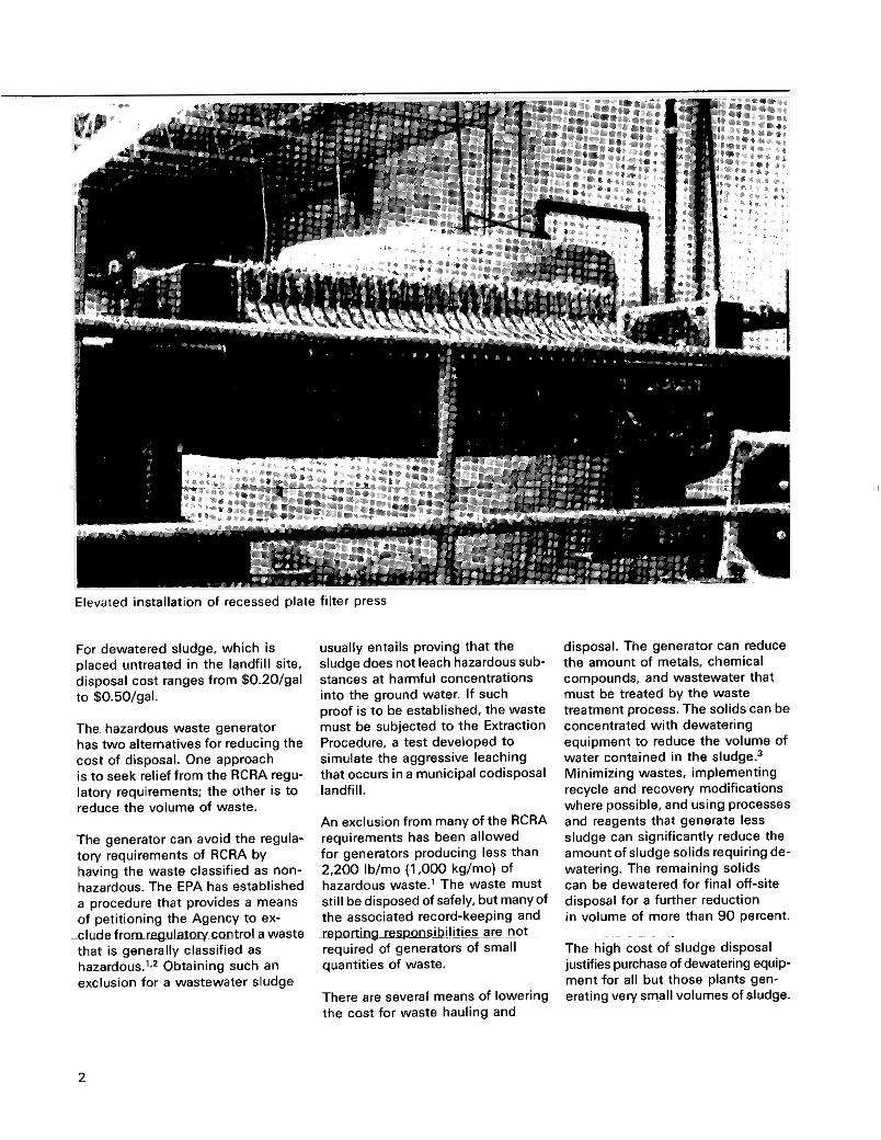
Elevated insiallat on of recesseo plate fi.ter Dress
For dewatered sludge, which is placed untreated in the landfill site. disposal cost ranges from $0.20/gal to $0.50/gal.
The hazardous waste generator has two alternatives for reducing the cost of disposal. One approach is to seek relief from the RCRA regu- latory requirements; the other is to reduce the volume of waste.
The generator can avoid the regula- tory requirements of RCRA by having the waste classified as non- hazardous. The EPA has established a procedure that provides a means of petitioning the Agency to ex-
d u d e from~regula~olycMtroI awasE that is generally classified as hazardous.’,2 Obtaining such an exclusion for a wastewater sludge
usually entails proving that the sludge does not leach hazardous sub- stances at harmful concentrations into the ground water. If such proof is to be established, the waste must be subjected to the Extraction Procedure, a test developed to simulate the aggressive leaching that occurs in a municipal codisposal landfill.
An exclusion from many of the RCRA requirements has been allowed for generators producing less than 2,200 Ib/mo (1,000 kg/mo) of hazardous waste.’ The waste must still be disposed of safely, but many of the associated record-keeping and -rewltingrespmslbi!akz a ~ e ~ ! ~ o t ~ ~~
required of generators of small quantities of waste.
There are several means of lowering the cost for waste hauling and
disposal. The generator can reduce the amount of metals, chemical compounds, and wastewater that must be treated by the waste treatment process. The solids can be concentrated with dewatering equipment to reduce the volume of water contained in the ~ l u d g e . ~ Minimizing wastes, implementing recycle and recovery modifications where possible, and using processes and reagents that generate less sludge can significantly reduce the amount of sludge solids requiring de- watering. The remaining solids can be dewatered for final off-site disposal for a further reduction in volume of more than 90 percent.
The high cost of sludge disposal justifies purchase of dewatering equip- ment for all but those plants gen- erating very small volumes of sludge.
~ ~~ ~~
2
The properties of individual sludges vary widely, however, and some form of pilot testing is needed to determine whether a particular type of dewatering equipment is suitable.
Of the types of equipment available, filter presses are usually the least expensive to install. Filter presses have further advantages in their mechanical simplicity and in their ability to achieve higher cake solids concentrations than other de- watering equipment types. Good performance with a filter press requires a sludge with good filtration characteristics. Sludges that have highly compressible, delicate
particles or that tend to blind the media are not well suited for equip- ment of this type.
Poor-filtering sludges can be dewatered by centrifuges, pressure belt filters, or vacuum filters that use a precoat filter aid. These devices are more mechanically sophisticated than filter presses and usually cost more. Their automa- tion, however, often reduces the need for operating labor.
This report is provided to aid the metal finisher in assessing waste gen- eration alternatives and developing
a cost-effective means of compliance with the regulatory requirements. The section that follows constitutes an overview of the regulatoly framework developed for hazardous waste disposal. Section 3 reviews the disposal methods and associated costs of commercially operated secure chemical landfills. Section 4 reviews factors influencing waste generation and describes what can be done to reduce waste volume and the cost of disposal. The main emphasis of the report is the final section, which evaluates the types of dewatering equipment available and their cost and performance.
..
3
2. Resource Conservation Recovery Act
On May 19, 1980, EPA issued regu- lations under RCRA as a basis for a national hazardous waste manage- ment program. The regulations came as a result of 1976 Congres- sional legislation that directed EPA to:
0 Identify those wastes that are hazardous
0 Establish national standards for generators and transporters of hazardous wastes and for operators of hazardous waste man- agement facilities involved in the storage or disposal of these wastes
and
Hazardous wastes are regulated from the time they are created to the time of their disposal. This cradle- to-grave monitoring is achieved by a manifest system?' Any waste that is transported off site for treatment, storage, or disposal must be accompanied by a manifest that:
0 Identifies whogenerated thewaste 0 Provides a full description of the
contentsand quantityofthe waste 0 Designates the facility to which
the waste must be shipped
Under RCRA, EPA holds the generator of a waste responsible for the ulti- mate safe disposal of that waste. Strict civil penalties can be imposed for any violations of the regulations. In addition, regulations governing the transportation of hazardous materials over public roads were pub-
lished on May 22, 1980, by the U.S. Department of Transportation ( ~ 0 ~ 1 . 7
Table 1.
Structure of RCRA Subtitle C Regulations
Regulatory Framework
Table 1 gives the structure of the RCRA regulations. Part 261 of Subtitle C defines four characteristics of wastes that would present an environmental threat if disposed of improperly (Table 2). A solid waste is hazardous if it exhibits any of these four characteristics, or if it is spe- cifically listed in Part 261 as haz- ardous.' In the latter case, EPA evaluated the hazard associated with unregulated disposal of wastes for which adequate information was available. Then, if the findings so warranted, the Agency made a general determination that a given waste is hazardous. Figure 1 shows the four common plating shop wastes that are generally classified as hazardous. All four wastes were determined to be toxic; plating baths, sludge from plating baths, and stripping and cleaning solutions may exhibit reactive properties as well.
RCRA standards for solid waste generators such as plating shops are defined in Part 262 of Subtitle C.4 They include provisions for record keeping, reporting. implementing a manifest system, and obtaining an EPA identification number.
Description Pan (40 CFR)
General provisions and definitions ..............................
Standards applicable to: ~~
~~ ~~~ ~~~ ~~~~~~~ ~ ~~ ~~~ ~~ ~ ~ ~ ~ ~ ~~ ~~ of.49 CER) ~ ~~
260 261
262. Sec. 262.34 263 (and Pts. 171-179
264
Identification and listing of hazardous waste.. ....................
Generators storing wastes <90 d Transporters, , . . . . . . . . . . . . . . . . . . . . . . . . . . . . . . . . . . . . . . . . . .
Permitted treatment. storage. and dispose1 facilities . . . . . . . . . . .
Permits for treetment. storage. and disposal facilities . . . . . . . . . . . . . .
Interim status standards applicable to treatment. storage. and disposal facilities. . . . . . . . . . . . . . . . . . . . . . . . . . . . . . . . . . . . . . . . . . . 265
122. 124 123 Guidelines for State hazardous weste programs.. . . . . . . . . . . . . . . . . .
SOURCE: U.S. Environmental Protection Agency. "Hazardous Waste Management System: General." Fedem/ Regisfer 45(98):33067. May 19. 1980.
4

Table 2.
Four Hazardous Waste Characteristics
Characteristic Description
Ignitabiiity., . . , . , . . . . . . . The waste is capable of causing fires during routine transpolfation to statage and disposai. or of burning so vigorously as to create B hazard.
The waste is aqueous and has a pH 5 2 or 21 2.5 or corrodes steel at a rate >0.25 inlyr.
The waste is extremely unstable and tends to react violently or explode, thus posing a problem st 811 Stages Of waste management.
Corrmivity.. . . . . . . . . . . . .
Reactivity . , , , , , , . . . . . . .
Extraction Procedure toxicity , , . . , . , , . . , , . . When the waste is subjected to a specified leaching procedure.
the leachate fraction contains certain contaminants in a concentration >lo0 times that specified in the National Interim Drinking Water Standards.
SOURCE: U.S. Environments1 Protection Agency, "Hazardous Wmte Management System: Identification and Listing of Hazardous Wastes." Fedem/ Register 45(98):33121-33122. May 19. 1980.
Workflow Product
.c--- A
Strlpplng and I I Plating bath , , 1 Rinse water c1emng SOl " t l 0 "S (FOO8, F007) (FOOS)
Effluent
Wastewater trestment
Hazardous waste Hazard code EPA hazardous waste no.
F006 Wastewmr treatment sludge Toxic
F007 Spent plating solutions Reactive, toxic FOO8 Spent plating bath and sludges Reactive, toxic
F009 Spent stripping and cleaning Reactive. toxic
from electroplating operations
from bottom of bath
solutions
Figure 1.
Hazardous Wastes from Electroplating Operations
If a hazardous waste is transported off site for treatment, storage, or disposal, the generator must pre- pare a man i fe~ t .~ .~ The manifest designates the treatment, storage, or disposal facility to which the waste is being transported; in the event an emergency prevents delivery to this facility, an alternate receiv- ing facility is designated. The manifest must contain a full descrip- tion of the waste being shipped in terms of contents and quantity, and it must identifythegeneratorand transporter. Sufficient copies of the manifest are needed to provide a copy for the records of the gen- erator, each transporter, and the receiving facility, as well as a copy to be returned to the generator after disposal of the waste.
The EPA considers that a generator storing hazardous waste on site for more than 90 days is an operator of a storage facility, and therefore must have applied for a facility permit before November 19,1980, to continue such operations.6 Storage for less than 90 days does not require a permit, but certain standards must be met. Regulations specify:
0 Provisions for inspection of
Precautions for ignitable or reac-
0 Personnel training 0 Contingency plans and emergency
procedures for dealing with the release of hazardous wastes from their containers or tanks
The hazardous waste management regulations issued on May 19. 1980, specified that plants operating a waste treatment system regulated by the Clean Water Act still had to comply with the RCRA standards for hazardous waste treatment and
comments on the regulations, EPA decided to award operators of wastewatertreatmenrand neutraliza- ~ ~ ~~ ~~
tion units a permit-by-rule if they comply with certain specified standards. Accordingly, plants with waste treatment facilities do not have to applyfora treatment and stor-
containers
tive waste containers
storage facilities. After reviewing ~~
..
5
age facility permit or comply with the interim status standards for those facilities. (Some State agencies administering the RCRA Program, however, have not adopted the permit-by-rule exclusion.) Details of this Wastewater Treatment Tank Exclusion were published on November 17, 1980.*
Exclusion from RCRA
Costs related to RCRA compliance can be lowered in one of two ways. The rate a t which hazardous waste is generated can be reduced to below 2,200 I b h o (1,000 kglmo), or the generator can have the waste declared nonhazardous.'
Reducing the Waste Generation Rate. An exclusion from many of the RCRA requirements has been allowed for generators producing less than 2,200 Iblmo (1.000 kglmo) of hazardous waste (small genera- tors), This upper limit applies to the total mass of waste and includes water and other nonhazardous constituents. The waste must still be disposed of either in authorized hazardous waste management facilities or in facilities approved by a State agency for municipal or industrial waste disposal. The associated record keeping, reporting. and waste manifest are not required of the small generator. Lacking an EPA identification number and waste manifest, however, the gen- erator may have more difficulty in finding a disposal facility that will accept metal finishing wastes. Moreover, within 2 to 5 yr. EPA may initiate rules to include in the RCRA requirements small gen- erators producing more than 220 Ib/mo (100 kglmo) of hazardous waste.
Seeking Nonhazardous Status. For some plating shops, having the waste declared nonhazardous (delisted) is effective in reducing RCRA-related costs.'.2 The EPA has established an appeals procedure that provides a generator with a means of petitioning the Agency to
~~~~~~~~~~~~~~~~~~~~~ ~~~ ~~~~~ ~
exclude from the regulatory controls a waste that is usually classified as hazardous. The Agency has authority to grant a temporary exclu- sion on the grounds of significant likelihood that the appeal will be successful.
A plating shop seeking to have its waste delisted must prove its waste nonhazardous, which means proving that the waste does not ex- hibit toxic or reactive characteristics. Proving the waste nonreactive generally requires testing to verify a low level of cyanide. Proving the waste nontoxic requires subjecting the waste to the Extraction Pro- cedure and proving that the sludge could not leach hazardous sub- stances at harmful concentrations into ground water. The Extraction Procedure is designed to sim- ulate the aggressive leaching that occurs in municipal codisposal land- fills. A sample of the waste is extracted and analyzed to determine whether it possesses any toxic contaminants identified in the National Interim Primary Drinking Water Standards (NIPDWS) and, if so. at what levels. The waste will be considered hazardous if it contains concentrations of contaminants 100 times greater than those speci- fied in the NIPDWS (Table 3). In addition, a complete chemical assay of the waste must be included in the delisting petition.
If a waste is to be delisted, it must be tested for each characteristic that is assumed to be present. Sufficient tests (at least four) of each type must be conducted to ensure repre- sentative results. Costs to perform the testing should range between $300 and $1.000. The test results are an essential step in the appeals procedure. Every reason for a waste being judged hazardous must be refuted. Even if a waste passes
_the extraction Procedure, hQWeVer,~ EPA may rule that sufficient hazard exists to warrant denying the appeal.
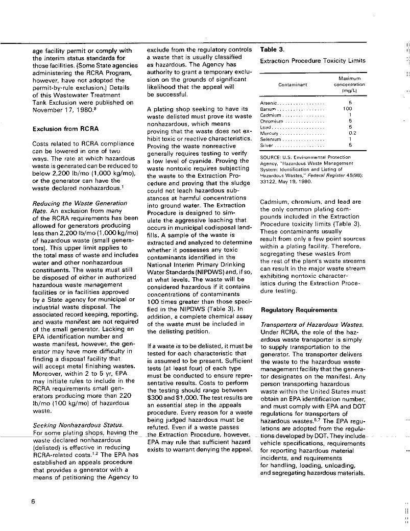
Table 3. Extraction Procedure Toxicity Limits
Maximum Conlaminant concentretion
h / L I
Arsenic . . . . . . . . . . . . . . . . . . 5 Barium. . . . . . . . . . . . . . . . . . 100 Cadmium . . . . . . . . . . . . . . . 1 Chromium . . . . . . . . . . . . . . . 5 Lead . . . . . . . . . . . . . . . . . . . . 5 Mercury . . . . . . . . . . . . . . . . . 0.2 Selenium . . . . . . . . . . . . . . . . 1 Silver . . . . . . . . . . . . . . . . . . . 5
SOURCE: U.S. Environmental Protection Agency, "Hazardous Waste Management System: Identification and Lisling of Hazardous Wastes," Federal Register 45/98): 33122. May 19, 1980.
Cadmium, chromium, and lead are the only common plating com- pounds included in the Extraction Procedure toxicity limits (Table 3). These contaminants usually result from only a few point sources within a plating facility. Therefore, segregating these wastes from the rest of the plant's waste streams can result in the major waste stream exhibiting nontoxic character- istics during the Extraction Proce- dure testing.
Regulatory Requirements
Transporters of Hazardous Wastes. Under RCRA, the role of the haz- ardous waste transporter is simply to supply transportation to the generator. The transporter delivers the waste to the hazardous waste management facility that the genera- tor designates on the manifest. Any person transporting hazardous waste within the United States must obtain an EPA identification number, and must comply with EPA and DOT regulations for transporters of hazardous The EPA regu- lations are adopted from the regula-
vehicle specifications, requirements
incidents, and requirements for handling, loading, unloading, and segregating hazardous materials.
~~
tions~developed by-DOT: They include- ~~
for reporting hazardous material ..
6
The requirements for transporters apply to both inter- and intrastate transportation and are enforceable by EPA or DOT.
A transporter may not accept a hazardous waste from a generator unless both parties have an EPA identification number and the waste is accompanied by a signed manifest. The transporter must sign the manifest and return a copy to the generator before leaving the gen- erator's property. When the ship- ment is transferred to another transporter or to the designated hazardous waste management facil- ity, the original transporter must obtain the signature of the next party on the manifest and keep one copy. The second transporter re- tains one copy of the manifest and transmits the remaining copies to the next party. The designated treatment, storage, or disposal facility is required to send one copy, with all the signatures, back to the generator. Special requirements exist for bulk shipments by rail or water.
Treatment, Storage, and Disposal Facilities. Facilities that treat, store, or dispose of hazardous wastes are also regulated under RCRA.e In.
terim operating permit status has been granted to all such facilities pro- vided they:
a Had been in operation or under construction before November 19. 1980
a Had notified EPA of their haz- ardous waste activities by August 18, 1980
vember 19, 1980 a Had applied for a permit by No-
Requirementsfor disposal sites cover
a General facility standards a Emergency precautions and actions
The manifest system a Record keeping and reporting
Requirements forfacilities on interim status cover:
a Reactive, ignitable, and incom-
a Closure and postclosure care a Containers and tanks
Surface impoundment, waste piles,
a Incinerators a Underground injection a Thermal, chemical, physical.
and biological treatment a Financial responsibility and
liability
patible wastes
land treatment, and landfills
For the foreseeable future, disposal in a landfill is the onlyfeasible method of disposing of many hazardous
~ ~~~
wastes. The regulations are intended to provide long-term protection of ground water and human health. They specify monitoring require- ments; failure to monitor the land treatment facility is a viola- tion of the regulations. They include requirements for controlling and monitoring water run-on and run-off, as well as general requirements for ignitable, reactive, and incompat- ible wastes. Owners and operators must consider specific factors and methods in addressing closure and postclosure requirements. Also, record keeping and surveying are required so that the exact loca- tion and contents of each waste cell will be known.
EPA has proposed financial require- ments intended to ensure that funds will be available for closure of treatment, storage, and disposal facilities, and for postclosure monitoring and maintenance a t disposal facilities.9 The proposed requirements also include liability coverage for injuries resulting from operation of a hazardous waste management facility. These pro- posals allow a number of ways to provide financial insurance.
7
3. Hazardous Waste The secure chemical landfill is the state of the art for disposal of metal finishing waste treatment Disposal Sites It is designed to preclude the risk of ground water contamination by toxic heavy metals that would leach through the soil and into the ground water unless prevented from doing so. The secure chemical landfill provides a means by which toxic wastes can be buried in an environmentally acceptable manner.
Landfill Design
There are basically two designs for a secure chemical landfill. The first takes advantage of natural geological barriers created by imper- meable clays. The second adds a flexible elastomer liner as further pro- tection against leaching of pollut- ants into the ground water. In both cases, disposal involves direct burial of wastes in cells designed to avoid contaminating the surround- ing environment.
The wastes to be buried are classified and segregated, and their positions within a burial cell are recorded. Bulk liquid wastes are solidified with lime or cement dust before burial; bulk solids are buried directly. Drums of wastes are surrounded by sufficient sorbent material to ab- sorb the entire contents of the drum, thereby eliminating the presence of any free liquids in the cell. Only compatible wastes are placed in a given disposal cell. When a cell is full, a compacted clay cover is placed over the top to prevent precipitation from filtering into the cell, thereby minimizing the formation of leachate and preventing its migration from damaged drums.
A piping system for leachate collec- tion is buried in a permeable bot- tom layer at the center of each cell. All leachate is recovered and
7S~peiiodically pum-ped~out of the cell through a standpipe connected to the piping system. The recovered leachate is solidified, then buried in the landfill. A monitoring-well system is placed outside the landfill cells for early detection
of any leachate that may leak out of the area. A properly operated secure chemical landfill does not usually experience leachate in its monitoring wells.
Waste Identification Procedure
Before a hazardous waste disposal site will accept a waste fordisposal, it will require the generator to submit a completed waste identification profile. The procedure includes an analysis of a sample of the waste to be landfilled. The analysis includes, for example, pH, flash point, and heavy metals content. From the pro- file and analysis, the disposal facility can determine whether the waste is compatible with the landfill disposal methods and operating permits. (Many secure chemical landfills do not accept re- active wastes containing cyanides.) If the waste is acceptable, the gen- erator prepares a shipping manifest that identifies the waste origin (generator), destination (disposal facility). hazard class and material identification number, EPA haz- ardous waste number, and weight. The manifest is carried by all transporters and is presented to the disposal facility when the waste is delivered. Appropriate copies of the manifest are returned to the transporter and the generator.
When the waste is received a t the landfill site, a representative sample is taken and analyzed to en- sure that the waste material received is the same as that identified by the waste profile documents. If the waste is accepted, it can then be landfilled. If rejected, it is usually re- turned to the generator.
Disposal Cost Factors
The total cost fordisposing of sludge wastes consists of the costs for hauling, for disposal site pre- treatment, and for landfilling. These costs depend on the physical nature and chemical composition of the wastes, and on the distance be-
..
a
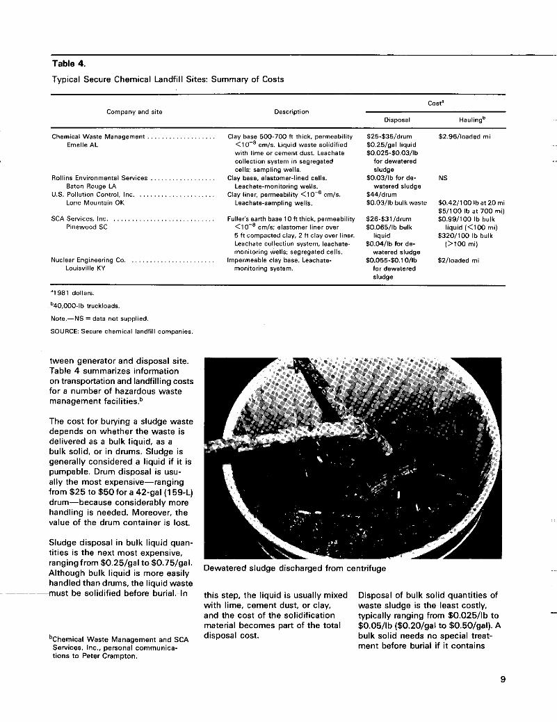
Table 4.
Typical Secure Chemical Landfill Sites: Summary of Costs
casta
oisposa1 Haulingb Company and site Description
Chemical Waste Management Emelle AL
RollinS Environmental Services . . . . . . . . . . . . Baton Rouge LA
Lone Mountain OK u s POllUtiD" Control. 1°C. . . . . . . . . . . . . . . .
. . . . . .
. . . . . .
SCA Services, Inc. . . . . . . . . . . . . . . . . . . . . . . . . . . . . Pinewood SC
Nuclear Engineering Co. Louisville KY
Clay base 500-700 f l thick. permeability <lo-' cmls. Liquid waste solidified with lime or cement dust. Leachate collection system in segregated cells: sampling wells.
Clay base. elastomer-lined cells. Leachatemonitoring wells.
Clay liner, permeability <lo-' c m l s . Leachate-sampling wells.
Fuller's earth bsse lof t th ick. permeability <IO-' cm/s: elastomer liner over 5 f t compacted clay. 2 ft clay over liner. Leachate Collection system. leachate- monitoring wells: segregsted cells.
monitoring system. Impermeable clsy base. Leschate-
$25-535/drum $0.25/gal liquid 50.025-50.03/1b
for dewatered sludge
50.03/lb fords- watered sludge
W41drum $0.0311b bulk waste
$26-$31/drum $0.065/lb bulk
liquid $0.04/lb for de-
watered sludge 50.055-50.1 Ollb
for dewatered sludae
52.96llaaded mi
NS
$0.42/100lbat20mi 551100 Ib a t 700 mi) 50.991100 Ib bulk
liquid (<lo0 mi) $3201100 Ib bulk
(>TOO mi)
52lloaded mi
'1981 dollars.
b40.000-lb trucklosds.
Note.-NS =data not supplied.
SOURCE: Secure chemical landfill companies,
tween generator and disposal site. Table 4 summarizes information on transportation and landfilling costs for a number of hazardous waste management facilitiesb
The cost for burying a sludge waste depends on whether the waste is delivered as a bulk liquid, as a bulk solid, or in drums. Sludge is generally considered a liquid if it is pumpable. Drum disposal is usu- ally the most expensive-ranging from $25 to $50 for a 42-gal (1 59-L) drum-because considerably more handling is needed. Moreover, the value of the drum container is lost.
Sludge disposal in bulk liquid quan- tities is the next most expensive, rangingfrom $0.25/gal to $0.75/gal. Although bulk liquid is more easily Dewatered sludge discharged from centrifuge
handled than drums, the liquid waste --must be solidified before burial. In this step, the liquid is usually mixed
with lime, cement dust, or clay, and the cost of the solidification material becomes part of the total disposal
Disposal of bulk solid quantities of waste sludge is the least costly, typically ranging from $0.025/lb to $0.05/lb ($0.20/gal to $0.50/gal). A bulk solid needs no special treat- ment before burial if it contains
bChemical Waste Management and SCA Services, Inc.. personal communica- tions to Peter Crampton.
9

no free liquid. Also, the overall cost of disposal is lower per unit of dly solids because of the smallervolume of the water associated with the waste. In general, the average disposal costs for all bulk loads of sludge are approximately $0.25/gal (see Table 4). Unfortunately. some disposal sites do not have the material-handling capabilities to dispose of nonpumpable wastes. It is important, therefore, to determine the local disposal conditions before developing a waste disposal strategy.
The cost for hauling sludge wastes depends on three significant factors:
0 Load size e Distance hauled e Fuel costs
Atypical bulk load of sludge is hauled by a truck with a 40,000-lb (1 8,000- kg) capacity. A load that is less than full will incur the same haul- ing cost as a full load. From Table 4, the average hauling cost is $3 per loaded mile in bulk loads. Therefore, if a bulk load of sludge is hauled 300 mi (480 kin), the average hauling cost is about $0.18/gal. When sludges are hauled to distant disposal sites, it is common for a number of small generators to com- bine and thus make full use of the hauling capacity of a truck. To maintain proper responsibility for the individual waste volumes, the wastes are segregated in sepa- rate hoppers or drums.
Pretreatment Capabilities
In general, the hazardous waste management facility does not
pretreat or process sludge wastes on site except to mix liquid waste with solidification materials. Physical or chemical treatment-such, as de- watering, dlying, or pH adjustment- is not performed on site. Some of the large chemical waste disposal companies do have or are planning to have facilities that offer a wide range of treatment capabilities. For example, RCRA does not allow land- fill disposal of sludges containing reactive materials such as cyanide. The disposal facility would therefore increase its potential market by providing chemical treatment for cyanide oxidation, making these wastes compatible for landfill disposal. As an alternative to solidifying dilute sludges, sludge dewatering could also be done at the treatment facilities.
10
4. Reducing Sludge Sludge handling and disposal costs
Generation and Cost ,,f normally depend heavily on sludge volume. The high cost of disposal
Disposal provides a strong incentive for modi- wing plating procedures to reduce this volume. A program to mini- mize chemical losses and watercon- sumption can reduce sludge gener- ation ~ignificantly.'*-'~ After wastewater treatment, the dilute sludge can be dewatered mechani- cally to reduce the volume by 90 to 95 percent.
Many factors contribute to the formation of insoluble solids during wastewater treament: major factors are:
Concentration of heavy metals and otherdissolved solids that pre- cipitate during treatment Volume of water to be treated Reagents, conditioners, and unit processes used in treatment
Incremental reductions in the amount of hazardous waste generated will lower disposal costs. Reducing the waste generation rate to below 2,200 Iblmo (1,000 kglmo) will
exempt the plant from reporting re- quirements defined in RCRA for hazardous waste generators. Eliminating toxic materials (cad- mium, lead, chromium) from the waste stream will result in a sludge that would prove nonhazardous if analyzed according to the Extrac- tion Procedure.
Reducing Sludge Generation
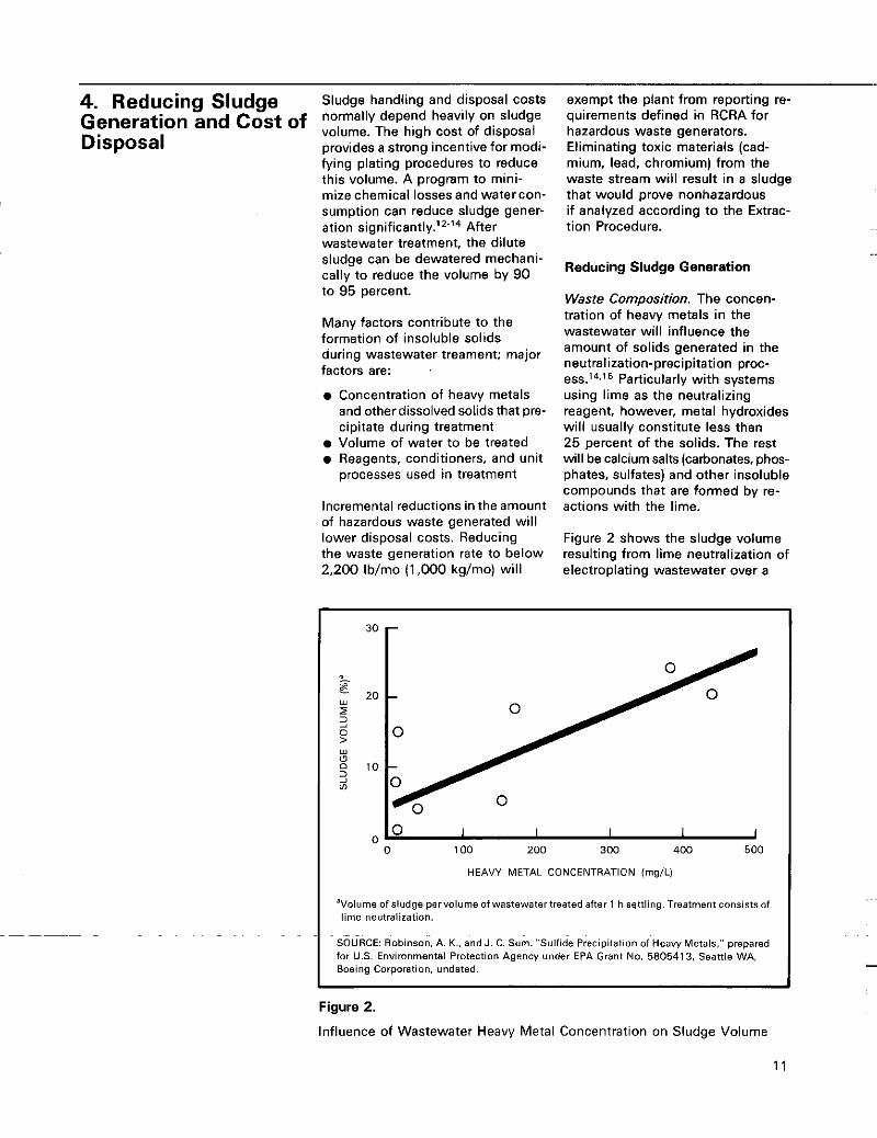
Waste Composition. The concen- tration of heavy metals in the wastewater will influence the amount of solids generated in the neutralization-precipitation proc- ess.14,15 Particularly with systems using lime as the neutralizing reagent, however, metal hydroxides will usually constitute less than 25 percent of the solids. The rest will be calcium salts (carbonates. phos- phates, sulfates) and other insoluble compounds that are formed by re- actions with the lime.
Figure 2 shows the sludge volume resulting from lime neutralization of electroplating wastewater over a
0 1 I I 1 I 0 100 200 300 400 500
HEAVY METAL CONCENTRATICN (mg/L)
'Volume of sludge pervolume of wastewatertreated after 1 h settling. Treatment consists of lime neutralization.
~ ~~
SOURCE: Robinson, A. K.. and J. C. Sum. "Sulfide Precipitation of Heavy Metals:' prepared for U.S. Environmental Protection Agency under EPA Grant No. 5805413, Seattle WA. Boeing Corporation, undated.
Figure 2.
Influence of Wastewater Heavy Metal Concentration on Sludge Volume
1 1
~ ~ ~ ~~~~
range of heavy metal concentrations. Based on the relationship shown, lime neutralization of 1,000 gal (3,800 L) of wastewater containing 100 mg/L of heavy metals would yield, after 1 h of settling, 90 gal (340 L) of sludge. Although the data do not define the suspended solids concentration of the sludge, metal hy- droxide sludges will typically gravity settle to between 1 and 5 percent solids by weight.
Reducing chemical losses, therefore, will reduce sludge generation rates as well as chemical replacement and wastewater treatment costs. The in-plant modifications that can reduce chemical losses are well-documented16-'8 and include such procedures as:
Dragout recovety and recycle Maximum use of 'stripping and cleaning solutions before they are discarded Drip trays and splash guards to direct losses back to the bath A good housekeeping and maintenance program to permit rapid finding and repair of leaks in tanks, valves, and pump seals
Table 5 gives the amount of metal hydroxide solids precipitated
during treatment for various metals in the raw wastewater, as well as the associated sludge volume at 3 percent and 25 percent solids by weight. Loss of 1 Ib (0.45 kg) of nickel into the wastewater will result in 6.1 gal (23.1 L) of sludge at 3 per- cent solids by weight. The cost of disposing of this volume of sludge will usually be greater than the original cost of the nickel salt.
Wafer Use. The amount of sludge generated is also affected by the volume of water needing treatment.15 In areas of hard water, precipitation of natural water contaminants, such as carbonates and phosphates, can generate a sludge volume exceeding that associated with chemicals discharged to the waste stream. Moreover, consumption of many treatment reagents and chem- ical conditioners used in waste- water treatment depends on the vol- ume of water treated. These com- pounds frequently end up in the sludge and increase its volume.
Several steps can be taken to reduce water use.16-18 The major water requirement is for rinsing; multiple stage counterflow rinse sys- tems and adequate agitation in the rinse tank will significantly reduce the amount of rinse water needed. For
Table 5
automated plating lines, flow restric- tors on the rinse water feed can be used to control fresh water additions at the minimum required for good rinsing. Rinse tank conductivity meters can do the same for inter- mittent plating operations. Reusing spent rinses or treated effluent for less critical water requirements will reduce water consumption.
The benefits of reducing water use go far beyond decreasing the amount of sludge generated, but the impact on sludge disposal should not be ignored in cost-benefit evaluation of potential modifications.
Pretreating the water to reduce its hardness level can reduce the contribution of naturally occurring water contaminants to sludge gen- eration. Water softeners using ion exchange resins or reverse osmosis systems can remove calcium and magnesium from water supplies.
Treatment Processes. The reagents, conditioners. and unit processes employed in wastewater treatment should be evaluated in terms of their effect on sludge generation rates. For example, lime and caustic soda are the two alkali neutraliz- ing agents used most frequently.'5 Lime has advantages over caustic soda in that it costs less per unit of neutralizing capacity, produces sludge that settles and dewaters more - readily, and can reduce the solubil- ity of metals to lower levels in some applications (primarily
Sludge Generated and Sludge Disposal Volume for Electroplating Waste Treatment System
because of the complex-breaking capabilities of the calcium ions). Lime has disadvantages, however, in
Waste metal components W b metal Generated that it requires a higher investment
bv weight) bv weight) longerto react in the wastewater, and, ... . . . . . . depending on the chemical comDo-
Sludge (gal/lb metal precipitated]
Dry solids
precipitated)' (a t3%so~ids (to 25%solids in the reagent feed system, takes
Aluminum .............................. Z.WY 1 1 .z 1.14 sition of the wastewater, can produce Cadmium . . . . . . . . . . . . . . . . . . . . . . . . . . . . . . 1.3 5
Chromium . . . . . . . . . . . . . . . . . . . . . . . . . . . . . 1.98 7.7 0.79 as much as 10 times the dly weight 0.51
Copper . . . . . . . . . . . . . . . . . . . . . . . . . . . . . . . . 1.53 5.9 0.6 of sludge produced by caustic soda. Iron . . . . . . . . . . . . . . . . . . . . . . . . . . . . . . . . . . . 1.61 6.2 0.63
~~
. . . . . . . . . . . . . . . . . . . . . . . . . . . . . . . . . ~ O . ' 2 Coagulating agents commonly Nickei 1.58 6.1 2,nc . . . . . . . . . . . . . . . . . . . . . . . . . . . . . . . . . . 1.52 5.9 0.6
used to improve floc formation before 'Using sodium hydroxide. clarification also can contribute to
sludge generation.12 Alum and ferric SOURCE: U.S. Environmental Protection Agency. Environmental Pollution Control Alternatives: Economics o f Wastewater Treatment Alternatives for the Electroplating Industv. EPA 625/5-79- 01 6, June 1979.
12
chloride are widely used, and ulti- mately both are converted to hydroxides and add to the amount of sludge for disposal. Although polyelectrolyte conditioners are more expensive than inorganic coagu- lants, they do not add to the quantity of sludge and have provided effective solids-settling rates. Their actual cost may therefore be lower.
The significance of treatment process selection can be appreciated when the different systems used to reduce chromium are consid- ered.l4.l5 Three types have been demonstrated:
Chemical reduction using a sulfur compound-sulfur dioxide (SO,) or sodium bisulfite (NaHSO,)
0 Electrochemical reduction using sacrificial iron electrodes Reduction using a slurry of in- soluble ferrous sulfide (FeS)
Using sulfur dioxide or sodium bisulfite has an advantage because, exceptforthe chromium, no insoluble byproducts are formed in the re- duction reaction:
350, + 2H,Cr04 + 3H,O - Cr,(SO,), + 5H,O
In electrochemical reduction units, an electric current is used to gen- erate ferrous ions that react with the hexavalent chromium ions:
3Fe+, + Cr0T2 + 4H,O - 3Fe+, + Cr+3 + 80H-
The ferric ions generated by the reduction will precipitate a t a neutral pH and add to the sludge volume.
Similarly, using ferrous sulfide as the reducing reagent will generate ferric ions and sulfur, both of which willadd to thesludgevolume:
H,Cr04 + FeS + 4H,O - Cr(OH), + Fe(OH), + S + 2H,O
tional factor to consider. Reduction using sulfur dioxide or sodium bisulfite requires a wastewater pH between 2 and 3. Consequently, a significant amount of acid may be needed to lower the pH. then a signif- icant amount of base would be needed to raise it back to neutral to precipitate the chromium as chromic hydroxide [Cr(OH),]. Electrochemical and ferrous sulfide reduction systems can operate at neutral pH. Particularly in sulfur dioxide and bisulfite reduction sys-
terns employing sulfuric acid and lime, the amount of calcium salts pre- cipitated can exceed the amount of precipitants resulting from the ferric ions and sulfur generated in the alternative reduction processes.
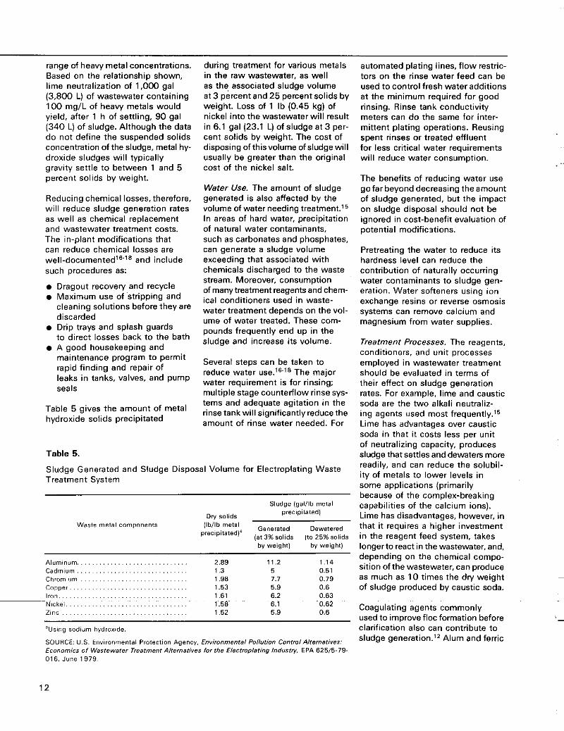
Figure 3 shows the sludge generation rates of the three reduction sys- tems over a range of hexavalent chromium concentration^.'^^'^ The electrochemical and ferrous sulfide processes actually generate less sludge solids at chromium concen-
..
ferrous sulfide reduction electrochemical reduction sulfur dioxide reduction
0 50 100 150 200
HEXAVALENT CHROMIUM (mg/L)
SOURCES: U S Environmental Protection Agency, Control and Treatment Technology for the Metal Finishing lndustw: Sulfide Precipitation. EPA 62518-80-003, Apr. 1980. U S Environmental Protection Agency. Economics of Wastewater Treatment Alternatites for the Electroplating Industv, EPA 62615.79-016. June 1979.
-It would appear that the electro- Figure 3. chemical and ferrous sulfide reduc- tion processes would be unfavorable, a t least in terms of sludge generation rates: however, there is an addi-
- Sludge Generation Factors for Alternative Chromium Reduction Processes
13
trations below 75 mg/L. It is im- portant to remember that the solids generation rates are based on assumptions regarding the initial pH of the wastewater and the neutral- izing reagent employed. Any firm conducting a similar analysis for its treatment system should test to determine how much sludge is generated by each of the differ- ent treatment alternatives.
To reduce sludge disposal costs, it is necessary to select the waste treatment techniques that generate the least amount of wastesludge.’2,13 Although some of the newer treat- ment techniques produce an effluent of high quality. they generate much more sludge than the conven- tional approaches they replace. The high cost of waste disposal re- quires that the foregoing sludge generation factors influence the selec- tion of wastewater treatment systems.
Sludge Dewatering
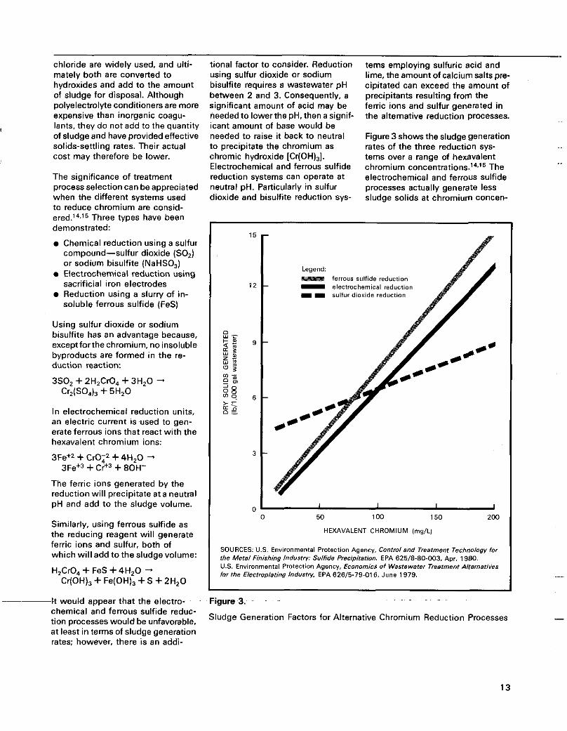
Although the volume of sludge can be reduced significantly by modifica- tions that reduce the pollutant and wastewater loadings on the treatment system, a sludge residue will result from wastewater treatment. The cost to dispose of this residue will depend primarily on volume. The volume of sludge can be reduced sinnificantlv bv mechanical de-
10 I I I I I I
0 5 10 15 20 25 30 35 J
SOLIDS CONCENTRATION 1% by weight]
Note.-Initial conditions. 1,000 gal a t 1% by weight.
watering equipment. Figure 4 shows Figure 4.
Sludge Volume versus Solids Concentration the reductions possible when sludge is dewatered from 1 percent solids bv weiaht to different solids - concentrations
Normally the clarifier underflow will contain between 0.5 and 3 per- cent solids by weight. Allowing the clarifier underflow to settle in a thickener tank will increase the solids content to between 2 and 5 percent by weight. Using the curve
in Figure 4, 1,000 gal (3,800 L)
of sludge at 1 percent solids byweight would be reduced to 330 gal (1,250 L) when thickened to 3 per- cent solids by weight. A mechanical dewatering device will achieve anywhere from 10 to 50 percent solids by weight, depending on the type of equipment and the dewatering properties of the sludge. Assuming dewatering to 25 per- cent solids by weight, the sludge vol- ume would be reduced to 40 gal (1 50 L)-4 percent of the original clarifier underflow volume.
Vacuum filters, filter presses, pressure leaf filters, belt filters, and centri- fuges have been applied successfully for mechanical dewatering of metal hydroxide sludges. The properties of individual sludges vary widely. however, and some pilot evaluations are necessary to determine whether a particular type of dewatering equipment is suitable. As a rule, equip- ment vendors will provide testing if supplied with a sample of the sludge.
14
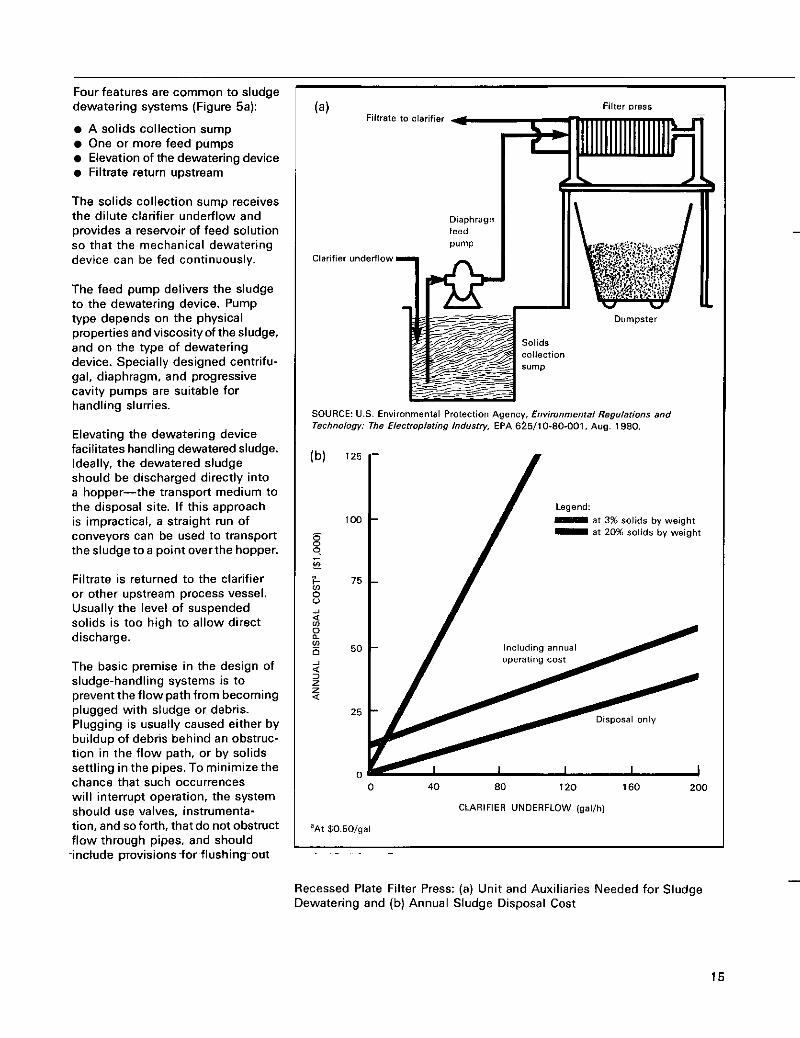
Four features are common to sludge dewatering systems (Figure 5a):
A solids collection sump One or more feed pumps Elevation of the dewatering device Filtrate return upstream
The solids collection sump receives the dilute clarifier underflow and provides a reservoir of feed solution so that the mechanical dewatering device can be fed continuously.
The feed pump delivers the sludge to the dewatering device. Pump type depends on the physical properties andviscosityof the sludge, and on the type of dewatering device. Specially designed centrifu- gal, diaphragm, and progressive cavity pumps are suitable for handling slurries.
Elevating the dewatering device facilitates handling dewatered sludge. Ideally, the dewatered sludge should be discharged directly into a hopper-the transport medium to the disposal site. If this approach is impractical, a straight run of conveyors can be used to transport the sludge toa point overthe hopper.
Filtrate is returned to the clarifier or other upstream process vessel. Usually the level of suspended solids is too high to allow direct discharge.
The basic premise in the design of sludge-handling systems is to prevent the flow path from becoming plugged with sludge or debris. Plugging is usually caused either by buildup of debris behind an obstruc- tion in the flow path, or by solids settling in the pipes. To minimize the chance that such occurrences will interrupt operation, the system should use valves, instrumenta- tion, and so forth, that do not obstruct flow through DiDes. and should
Filtrate to clarifier (a)
Diaphragm feed Pump
Clarifier underflow
Filter D ~ ~ S S
0"mpLter
SOURCE: U.S. Environmental Protection Agency. Envimnmental Reguletions and Technology: The Electroplating lndustw, EPA 6%/10-80-001, Aug. 1980 .
125
/ Legend:
0 40 80 120 1 6 0 200
CLARIFIER UNDERFLOW (gal/h)
'At 50.50/gal
- . . ~~~ -include provisions~for flushing~ out ~
Recessed Plate Filter Press: (a) Unit and Auxiliaries Needed for Sludge Dewatering and (b) Annual Sludge Disposal Cost
15
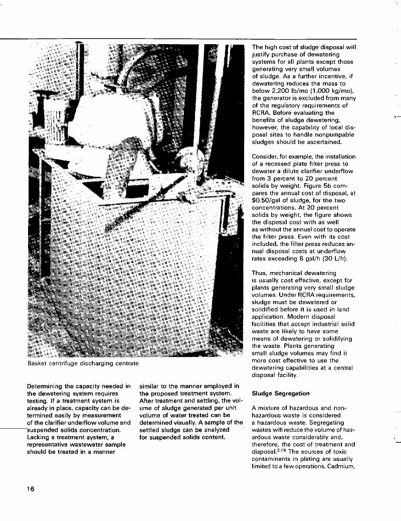
Basket centrifuge discharging centrate
Determining the capacity needed in the dewatering system requires testing. If a treatment system is already in place, capacity can be de- termined easily by measurement of the clarifier undelflow volume and suspended solids concentration. Lacking a treatment system, a representative wastewater sample should be treated in a manner
~
similar to the manner employed in the proposed treatment system. After treatment and settling, the vol- ume of sludge generated per unit volume of water treated can be determined visually. A sample of the settled sludge can be analyzed for suspended solids content.
The high cost of sludge disposal will justify purchase of dewatering systems for a l l plants except those generating very small volumes of sludge. As a further incentive, if dewatering reduces the mass to below 2,200 Iblmo (1,000 kglmo). the generator is excluded from many of the regulatov requirements of RCRA. Before evaluating the benefits of sludge dewatering, however, the capability of local dis- posal sites to handle nonpumpable sludges should be ascertained.
Consider, for example, the installation of a recessed plate filter press to dewater a dilute clarifier underflow from 3 percent to 20 percent solids by weight. Figure 5b com- pares the annual cost of disposal, at $0.50/gal of sludge, for the two concentrations. At 20 percent solids by weight, the figure shows the disposal cost with as well as without the annual cost to operate the filter press. Even with its cost included, the filter press reduces an- nual disposal costs at underflow rates exceeding 8 gal/h (30 Uh).
Thus, mechanical dewatering is usually cost effective, except for plants generating very small sludge volumes. Under RCRA requirements, sludge must be dewatered or solidified before it is used in land application. Modern disposal facilities that accept industrial solid waste are likely to have some means of dewatering or solidifying the waste. Plants generating small sludge volumes may find it more cost effective to use the dewatering capabilities a t a central disposal facility.
Sludge Segregation
A mixture of hazardous and non- hazardous waste is considered a hazardous waste. Segregating wastes will reduce the volume of haz- ardous waste considerably and, therefore, the cost of treatment and d i s p o ~ a l . ~ ~ ~ ~ The sources of toxic contaminants in plating are usually limited to a few operations. Cadmium,
7 -
16
lead, and chromium are the only common plating materials on the EPA list of toxic substances. If toxic wastes are separated from the rest of the waste stream, the treat- ment residue from the nontoxic waste streams should be able to pass the Extraction Procedure and be judged nonhazardous by EPA. Disposal of a waste that is judged nonhazardous should be less costly.
The segregated sludge containing toxic substances must be disposed of in a manner acceptable for haz- ardous wastes; however, the volume should be considerably less than the total amount of waste generated. The generator will avoid the report- ing and manifest requirements if the hazardous waste amounts to less than 2,200 I b h o (1.000 kglmo).
Toxic substances can also be eliminated from a plant’s waste by recovery and recycle of the toxic contaminants. Dragout from cadmium, lead, and chromium plating operations has been recov- ered by recovery systems. The combined benefits of material recov- ery, waste treatment cost reduction, and producing a nonhazardous sludge can provide significant returns on the investment in recovery equipment.
5. Sludge Dewatering Mechanical dewatering devices are used to achieve a higher sludge solids concentration than can be ob- Equipment
~~ ~~
tained by gravity thickening. Weak attractive forces bind much of the water contained in a sludge to the solid particles; when the bonds are subjected to mechanical force, much of the water remaining in the sludge aftergravity thickening can be removed. The following types of equipment can be used for mechanical dewatering of electro- plating sludges:
e Pressure filters e Vacuum filters e Centrifuges
Compression filters
When pressure filters are employed. the dilute sludge is pumped into the filter; the solids are retained on the filter membrane and the filtrate is discharged. Recessed plate filter presses use this method. They can dewater sludge to high solids content owing to the large pres- sure gradient they can apply across the sludge cake.
Vacuum filters dewater sludge by applying a vacuum on one side of a water permeable membrane that has a sludge layer or suspension on the other side. In response to the pressure gradient, the water passes through the membrane. Rotary drum and vacuum belt filters use this principle.
Centrifuges dewater sludge similarly to gravity thickening, but by rapidly rotating the sludge, they create a centrifugal force thousands of times more powerful than normal gravity. The strong centrifugal force greatly speeds up the settling process and magnifies the com- paction effect. This dewatering mechanism makes centrifuges most suitable for compressive sludges that settle well.
Compression filters dewater sludge by squeezing it between water permeable membranes. They have proven effective mainly for dewatering highly compressive sludges typical of those resulting from polyelectrolyte conditioning.
Criteria for selecting one of the foregoing devices for a specific a p - plication include:
e Sludge properties (solids
-
concentration, particle size, compressibility) Volume of sludge to be dewatered
e Local disposal requirements
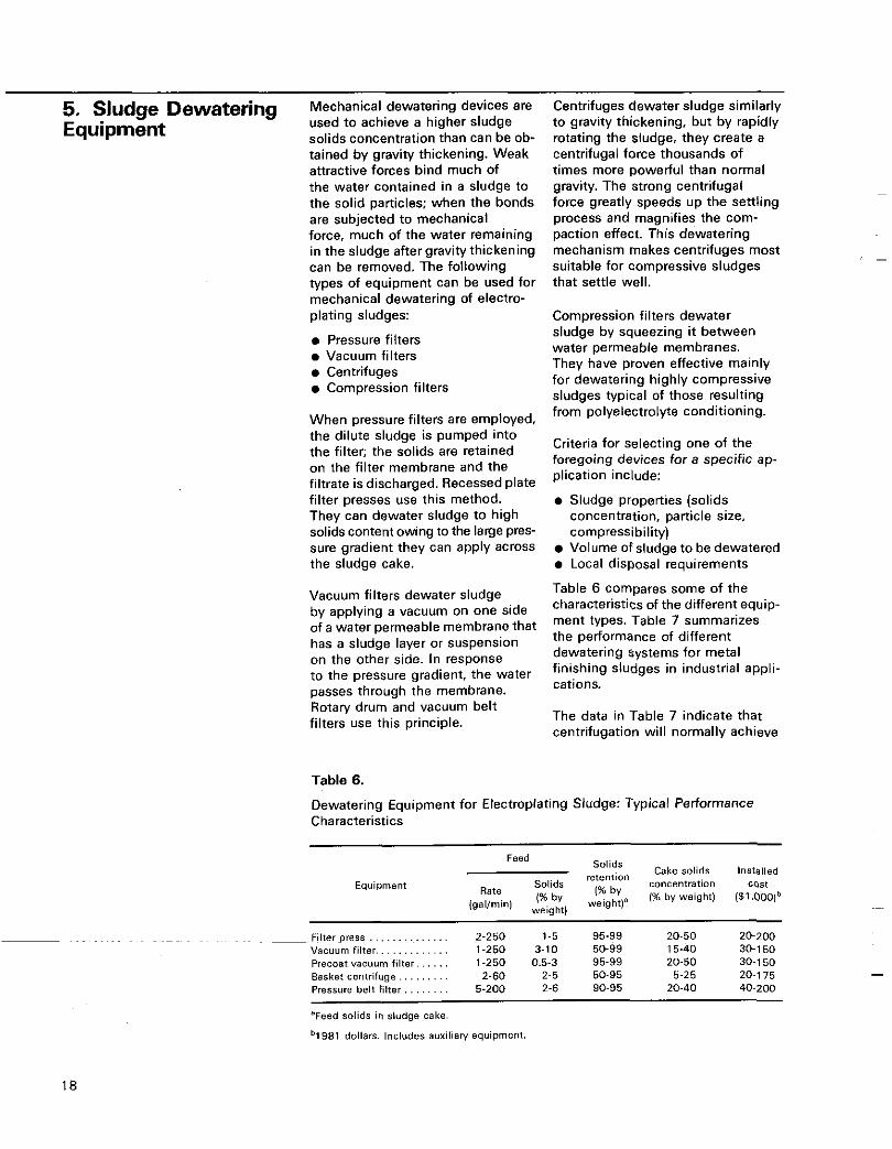
Table 6 compares some of the characteristics of the different equip- ment types. Table 7 summarizes the performance of different dewatering systems for metal finishing sludges in industrial appli- cations.
The data in Table 7 indicate that centrifugation will normally achieve
Table 6.
Dewatering Equipment for Electroplating Sludge: Typical Performance Characteristics
Solids Feed Solids retention Cake solids lnstglled
IgallminI (% by 1% by weight) (51.000)b by concentration Cost
Rate Equipment
Filter press . . , . . . . . . . . . . . 2-250 1-5 95-99 20-50 20-200 Vacuum filter.. , , . . . . , . . . . 1-250 3-10 50-99 15-40 30-1 50 Precoat vacuum l i l ter . . . . . . 1-250 0.5-3 95-99 20-50 30-1 50 Basket centrifuge.. . . . . . . . 2-60 2-5 50.95 5-25 20-1 75 Pressure belt f i l ter . . . . . . . . 5-200 2-6 90-95 20-40 40-200
'Feed solids in sludge cake.
b1981 dollars. Includes auxiliaw equipment.
18
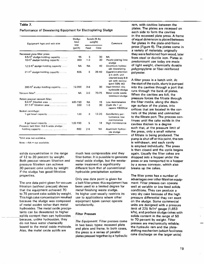
Table 7.
Performance of Dewatering Equipment for Electroplating Sludge
Sludge Solids I% by feed weight) rate
Comment Equipment type and unit Size
(gal/h) Feed Cake
Recessed plate filter press: 8.5-ft3 sludge-holding capacity. . . . . . 95 3 30 MA 10-ft3 sludge-holding capacity. . . . . . 300 1-2 30 Plastic-plating lime
sludge
ide dewsterino 12.5-ft3 sludgeholding capacity . . . . NA NA 40 Chromium hydrox-
21 .ft3 sludge-holding capacity.. . . . . 825 5 35-40 Operationattention 2-h shift: unit cleaned every 6-8 wk with recircu- lated 50% HCI
260-ft3 sludge-holding capacity.. . . . 12,000 3-6 30 Heat-treated zinc hydroxide sludge
vacuum f l l t d . . . . . . . . . . . . . . . . . . . . . . . . NA 3-5 70-75 Metal oxide waste treatment sludge
Rotary precost vacuum filter: 9.4-ft2 filtration area . . . . . . . . . . . . . . 100-150 NA 15 Low maintenance 37.1-ft' filtration area . . . . . . . . . . . . . 330 1-5 30 Cloth life 1 yr:
1-gal bowl capacity. . . . . . . . . . . . . . . 120 3 12-20 Satisfactovper-
4-gal bowlcapaci ty . . . . . . . . . . . . . . . 120-150 5 18 High maintenance
repairs <$200/yr Basket centrifuge:
formance; low maintenance
Pressure belt filter: 9.8-ft-wide sludge- holding capacity.. . . . . . . . . . . . . . . . . . . 800 2-6 NA Aluminum hydrox-
ide sludge
'Unit size not available.
Note.-NA= not available.
solids concentration in the range of 12 to 20 percent by weight. Both precoat vacuum filtration and pressure filtration can achieve 30 percent cake solids by weight if the sludge has good filtration properties.
The one data point given for vacuum filtration (without precoat) shows that the equipment achieved 70 to 75 percent cake solids by weight. This high cake concentration resulted because the sludge was composed of metal oxides rather than metal hydroxides. The metal oxide precipi- tants can be dewatered to higher
_solids content than can hydroxides because, unlike hydroxides, they do not have water chemically bound to the metal oxide molecule. Also, the metal oxide solids are
much less compressible and they filter better. It is possible to generate metal oxide sludge, but the waste- water treatment is significantly different from that of conventional hydroxide precipitation systems.
Only one data point is given for a beltfilter press; this equipment has been used to a limited degree for metal finishing waste sludge. Its higher cost usually restricts its use to applications where other equipment types cannot operate satisfactorily.
Filter Presses
The Equipment. Filter presses come in two basic types: recessed plate and plate and frame. In both cases, the press is a series of parallel plates pressed together by a hydraulic
ram, with cavities between the plates. The plates are recessed on each side to form the cavities in the recessed plate press. A frame of equal dimension is placed between flat plates in the plate-and-frame press (Figure 6). The plates come in a variety of materials: originally they were fashioned from wood, later from steel or ductile iron. Plates in predominant use today are made of light weight, chemically durable polypropylene or fiber-reinforced polyester.
A filter press is a batch unit. At thestartofthecycle,slurryispumped into the cavities through a port that runs through the bank of plates. When the cavities are full, the pressure forces the filtrate through the filter media, along the drain- age surface of the plates, into orifices that are located in the cor- ners of the plates and connected to the filtrate port. The process con- tinues until the cake solids in the cavities thicken to a degree such that, at the pressure limit of the press, only a small volume of filtrate is being produced. The pump is shut off a i this point, the ram is withdrawn, and each cavity is emptied individually. The press is then closed and the cycle begins again. Usually the filter cakes are dropped into a hopper under the press or are transported to a hopper by a screw conveyor, which also breaks up the cakes.
The filter press has a number of advantages over other filtration equip- ment. Filter presses can operate well at variable or low feed solids conditions. They can produce a very dry cake because of the high pressure differential they can exert on the sludge. Some commercial units are designed with a pressure limit of 225 Ib/in* gauge (1,653 kPa). and produce sludge cakes with solids content in the range of 50 to 70 percent by weight. Filter presses are mechanically reliable; the hydraulic ram and the plate- shifting mechanism (which facilitates cake discharge on the larger units)
19
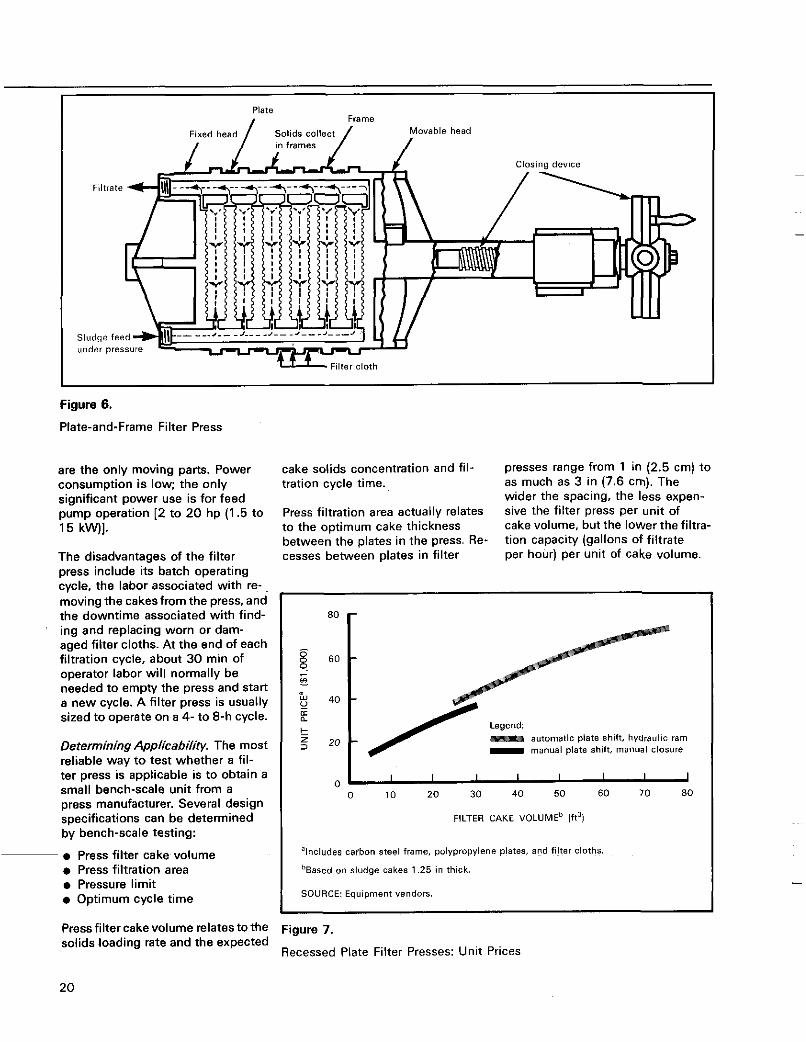
Plate Frame
Solids collect/ Movable head / in frames / Fixed head I
ing and replacing worn or dam- aged filter cloths. At the end of each filtration cycle, about 30 min of operator labor will normally be needed to empty the press and start a new cycle. A filter press is usually sized to operate on a 4- to 8-h cycle.
Determining AppiicaMity. The most reliable way to test whether a fil-
Filter cloth
e Press filter cake volume 0 Press filtration area e Pressure limit e Optimum cycle time
Figure 6.
Plate-and-Frame Filter Press
'Includes carbon Steel frame, polypropylene plates, and filter cloths.
'Based on sludge cakes 1.25 in thick.
SOURCE: Equipment vendors.
are the only moving parts. Power consumption is low; the only significant power use is for feed pump operation [2 to 20 hp (1.5 to 15 kW)].
The disadvantages of the filter press include its batch operating
cake solids concentration and fil- tration cycle time.
Press filtration area actually relates to the optimum cake thickness between the plates in the press. Re- cesses between plates in filter
presses range from 1 in (2.5 cm) to as much as 3 in (7.6 cm). The wider the spacing, the less expen- sive the filter press per unit of cake volume, but the lower the filtra- tion capacity (gallons of filtrate per hour) per unit of cake volume.
automatic plate shift. hyarsulic ram manual plate shift, manual closure
60
LU 40 v
t
n: a
0 I I I I I I I I
0 10 20 30 40 50 60 70 80
FILTER CAKE VOLUME^ (ft31
Press filter cakevolume relatestothe solids loading rate and the expected
Figure 7.
Recessed Plate Filter Presses: Unit Prices
20
Feed solids concentration and filter- ability of the sludge affect the choice of spacing.
Pressure limit relates to the solids content of the sludge cakeversus the applied pressure.
Optimum cycle time is determined bythe pressvolumeand filtrationarea specified. The longer the cycle time, the lower the labor require- ments, because cake discharge and restarting occur less frequently. A longer cycle time will require a larger unit, which of course will cost more.
Testing with a bench-scale filter press, however, can be costly and time consuming. The applicabil- ity of a filter press, or of any filtration technique, can be determined more simply by use of a filter leaf test apparatus.*O Several factors can be evaluated, for example, filter- ability, medium fouling, and cake release from the medium. Vendors of filter press equipment can scale up filter leaf test data to determine the required size of a filter press.
As an alternative to testing, filter press vendors need only a sludge sample and the volumetric rate and solids content of the press feed to determine the required size and cost of the unit.
Costs. Figure 7 shows the relation- ship of filter press purchase price to the volume of cake solids for a press with a 1.25-in (3.2-cm) cake recess and an operating pressure of 100 Ib/in2 gauge (790 kPa). The cost covers only the purchase price of the press; auxiliary equipment needed includes:
0 High pressure feed pump or pumps 0 Sludge feed storage 0 Filtrate return to the clarifier 0 Cake solids handling and discharge
The cost of auxiliaries can be considerable, but fortunately there are alternatives that can elim- inate some of the expense. Sludge
~~ ~~
feed piping, filter, and filtrate discharge piping can be designed as a closed hydraulic system. This ap- proach enables the sludge feed pump to provide the pressure head needed to return the filtrate to the clarifier, thus eliminating the need for a filtrate receiving tank and return pump in applications where gravity flow return is not feasible.
Handling and disposal of the cake solids can be simplified by elevation of the press, enabling the filter cake to be discharged directly into the disposal hopper. This approach will eliminate the need for solids conveying systems and reduce the amount of operator attention associated with discharge'of the cake solids.
Owing to the batch operation of the filter press, storage volume
is needed for the sludge feed. Normally, a sump to receive the clarifier underflow will provide the necessaly storage volume. If the solids retention time in a clarifier is high, the clarifier can be used as the storage chamber; otherwise a holding tank will be required to provide adequate sludge storage.
Operational costs associated with the press are for power to operate the feed pumps and labor to turn the press around at the end of each cycle. Minor operational costs are asso- ciated with maintaining the filter media in good condition. These costs include replacement of dam- aged or worn filter cloths and periodic cleaning to control media blinding.
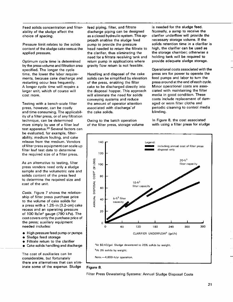
In Figure 8, the cost associated with using a filter press for sludge
1 4 0 1 120
Legend: II - disposal only
including annual cost of filter press
0 GO 120 180 240 300 360
CLARIFIER UNDERFLOWb (gal/h)
'At $O43/gal Sludge dewatered to 25% solids by weight
bAt 3% solids by weight
Note -4,800-h/yr operation
Figure 8.
Filter Press Dewatering Systems: Annual Sludge Disposal Costs
21
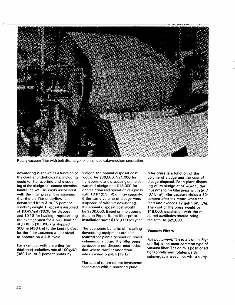
Rotary vacuum filter with belt discharge for enhanced cake-medium separation
dewatering is shown as a function of the clarifier underflow rate, including costs for transporting and dispos- ing of the sludge at a secure chemical landfill as well as costs associated with the filter press. It is assumed
weight, the annual disposal cost would be $39.000: 521,000 for transporting and disposing of the de- watered sludge and $1 8,000 for depreciation and operation of a press with 10 ft3 (0.3 m3) of filter capacity.
filter press is a function of the volume of sludge and the cost of sludge disposal. For a plant dispos- ing of its sludge a t $0.43/gal, the investment in a filter press with a 5-ft3 (0.1 5") filter capacity yields a 30-
that the clarifier underflow is dewatered from 3 to 25 percent solids byweight. Disposal isassumed at $0.43/gal (50.25 for disposal and $0.1 8 for hauling), representing the average cost for a bulk load of 40.000 Ib (18,000 kg) shipped 300 mi (480 km) to the landfill. Cost for the filter assumes a unit sized to operate on a 4-h cycle.
For example, with a clarifier (or -thickener) underflow rate of 100 gal/h (380 Vh) a t 3 percent solids by
If the same volume of sludge were disposed of without dewatering, the annual disposal cost would be $200.000. Based on the assump- tions in Figure 8, the filter press installation saves $1 61,000 per year.
The economic benefits of installing dewatering equipment are also realized for plants generating small volumes of sludge. The filter press achieves a net disposal cost reduc- tion where clarifier underflow rates exceed 5 gal/h (19 Uh).
The rate of return on the investment associated with a recessed plate
percent after-tax return when the feed rate exceeds 12 gal/h (45 Uh). The cost of the press would be $19.000: installation with the re- quired auxiliaries should bring the total to $29,000.
Vacuum Filters
The Equipment. The rotary drum (Fig- ure 9a) is the most common type of vacuum filter. The drum is positioned horizontally and rotates partly submerged in a vat filled with a slum/.
22
Dewatering zone
--
0 1 2 3 4
CYCLE (min/r)
Note.-Ai 3% feed solids by weight.
25 r
0 100 200 300 400 500 600
FEED RATE (yalih)
Note -At 3% feed solids by weight
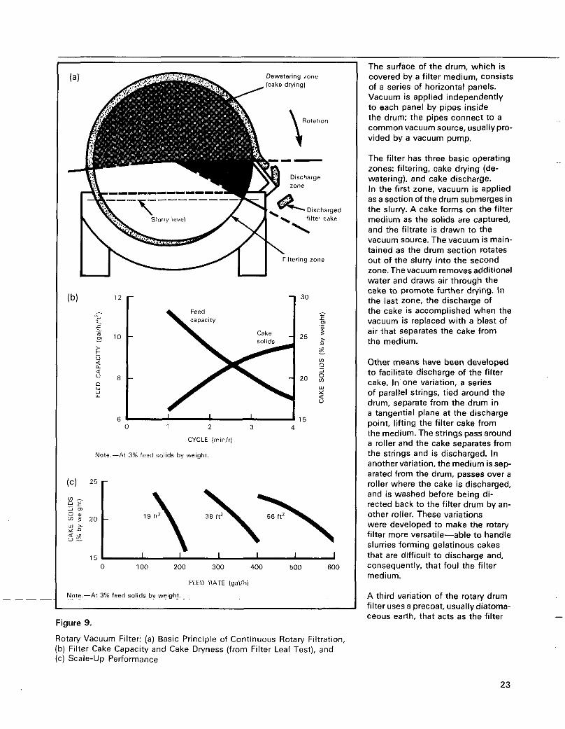
Figure 9.
Rotary Vacuum Filter: (a) Basic Principle of Continuous Rotary Filtration, (b) Filter Cake Capacity and Cake Dryness (from Filter Leaf Test), and IC) Scale-up Performance
The surface of the drum, which is covered by a filter medium, consists of a series of horizontal panels. Vacuum is applied independently to each panel by pipes inside the drum; the pipes connect to a common vacuum source, usually pro- vided by a vacuum pump.
The filter has three basic operating zones: filtering, cake drying (de- watering), and cake discharge. In the first zone. vacuum is applied as a section of the drum submerges in the slurry. A cake forms on the filter medium as the solids are captured, and the filtrate is drawn to the vacuum source. The vacuum is main- tained as the drum section rotates out of the slurry into the second zone. Thevacuum removesadditional water and draws air through the cake to promote further drying. In the last zone, the discharge of the cake is accomplished when the vacuum is replaced with a blast of air that separates the cake from the medium.
Other means have been developed to facilitate discharge of the filter cake. In one variation, a series of parallel strings, tied around the drum, separate from the drum in a tangential plane at the discharge point, lifting the filter cake from the medium. The strings pass around a roller and the cake separates from the strings and is discharged. In another variation, the medium is sep- arated from the drum, passes over a roller where the cake is discharged, and is washed before being di- rected back to the filter drum by an- other roller. These variations were developed to make the rotary filter more versatile-able to handle slurries forming gelatinous cakes that are difficult to discharge and, consequently. that foul the filter medium.
A third variation of the rotary drum filter uses a precoat, usuallydiatoma- ceous earth, that acts as the filter
23
medium. As the drum rotates past a scraper, a thin portion of the precoat cake is removed along with the collected solids, resulting in a clean, unfouled surface each time a sec- tion of the drum enters the slurry. Precoat filtration provides excellent filtrate quality and can remove slimy solids that are difficult to filter and that would rapidly foul a per- manent filter medium.
Precoatfiltration is generally used to dewater dilute sludges because it offers a high filtration rate per unit of filter area. Precoat consump- tion usually ranges from 5 to 20 Ib (5 to 20 kg) for each 100 Ib (100 kg) of sludge solids ($0.50- $21100 Ib sludge solids). The pre- coat does add to the quantity of solids for disposal, but often precoat filtration yields a cake with higher solids content than does standard vacuum filtration.
Determining Applicability. The filter leaf testz0 is the common proce- dure for evaluating the applicability of vacuum filtration and determin- ing required unit size. The filter leaf is a small disk with drainage arids similar to oroduction filters. Fil-
70
60
F 50
9 % “ul 40 v
t 5 30
0 - a a
20
10
F L Precoat w w u m
Legend 40
35
30
25
20
15
0 20 40 60 80 100 120
FILTER AREA (ft’)
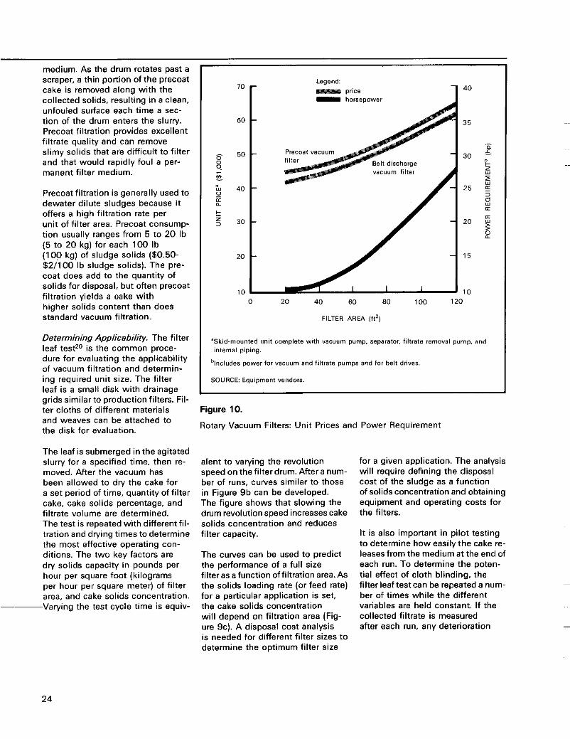
’Skid-mounted unit complete with v.%UUm pump. Separator. filtrate removal pump, and internal piping.
’Includes power for Vacuum and filtrate pumps and for belt drives.
SOURCE Equipment vendors
ier cloths of different materials and weaves can be attached to the disk for evaluation.
Figure 10.
Rotary Vacuum Filters: Unit Prices and Power Requirement
The leaf is submerged in the agitated slurry for a specified time, then re- moved. After the vacuum has been allowed to dry the cake for a set period of time, quantity of filter cake, cake solids percentage, and filtrate volume are determined. The test is repeated with different fil- tration and drying times to determine the most effective operating con- ditions. The two key factors are dly solids capacity in pounds per hour per square foot (kilograms per hour per square meter) of filter area, and cake solids concentration.
-Varying the test cycle time is equiv-
alent to varying the revolution speed on the filter drum. After a num- ber of runs, curves similar to those in Figure 9b can be developed. The figure shows that slowing the drum revolution speed increases cake solids concentration and reduces filter capacity.
The curves can be used to predict the performance of a full size filter as a function offiltration area.As the solids loading rate (or feed rate) for a particular application is set, the cake solids concentration will depend on filtration area (Fig- ure 9c). A disposal cost analysis is needed for different filter sizes to determine the optimum filter size
for a given application. The analysis will require defining the disposal cost of the sludge as a function of solids concentration and obtaining equipment and operating costs for the filters.
It is also important in pilot testing to determine how easily the cake re- leases from the medium a t the end of each run. To determine the poten- t ia l effect of cloth blinding, the filter leaf test can be repeated a num- ber of times while the different variables are held constant. If the collected filtrate is measured after each run, any deterioration
24
120
I O 0
so
60
40
20
0 0 100 200 300 400
CLARIFIER UNDERFLOWb (gallh)
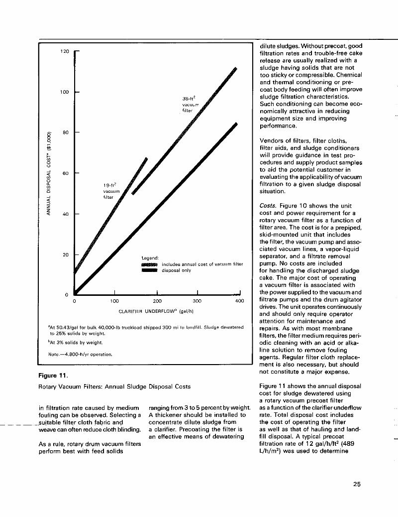
'At $0.43/gal for bulk 40,000-lb truckload shipped 300 mi to landfill. Sludge dewatered to 25% solids by weight.
'At 3% solids by weight.
Note.-4.800-h/yr operation.
Figure 11.
Rotary Vacuum Filters: Annual Sludge Disposal Costs
dilutesludges. Without precoat, good filtration rates and trouble-free cake release are usually realized with a sludge having solids that are not too sticky or compressible. Chemical and thermal conditioning or pre- coat body feeding will often improve sludge filtration characteristics. Such conditioning can become eco- nomically attractive in reducing equipment size and improving performance.
Vendors of filters, filter cloths, filter aids, and sludge conditioners will provide guidance in test pro- cedures and supply product samples to aid the potential customer in evaluating the applicabilityof vacuum filtration to a given sludge disposal situ at i o n . Costs. Figure 10 shows the unit cost and power requirement for a rotary vacuum filter as a function of filter area. The cost is for a prepiped, skid-mounted unit that includes the filter, the vacuum pump and asso- ciated vacuum lines, a vapor-liquid separator, and a filtrate removal pump. No costs are included for handling the discharged sludge cake. The major cost of operating a vacuum filter is associated with the power supplied to the vacuum and filtrate pumps and the drum agitator drives. The unit operates continuously and should only require operator attention for maintenance and repairs. As with most membrane filters, the filter medium requires peri- odic cleaning with an acid or alka- line solution to remove fouling agents. Regular filter cloth replace- ment is also necessary, but should not constitute a major expense.
Figure 1 1 shows the annual disposal cost for sludge dewatered using a rotary vacuum precoat filter
in filtration rate caused by medium fouling can be obselved. Selecting a
weave can often reduce cloth blinding.
As a rule, rotary drum vacuum filters perform best with feed solids
rangingfrom 3 to 5 percent by weight. A thickener should be installed to concentrate dilute sludge from a clarifier. Precoating the filter is an effective means of dewatering
as a function of the clarifier underflow rate. Total disposal cost includes the cost of operating the filter as well as that of hauling and land- fill disposal. A typical precoat filtration rate of 12 gal/h/ft2 (489 Uh/m2) was used to determine
~~ suitable filter cloth fabric and
25
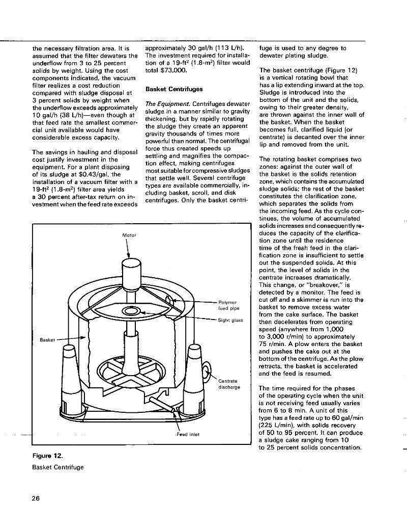
the necessary filtration area. It is assumed that the filter dewaters the underflow from 3 to 25 percent solids by weight. Using the cost components indicated, the vacuum filter realizes a cost reduction compared with sludge disposal a t 3 percent solids by weight when the underflow exceeds approximately 10 gal/h (38 L/h)-even though a t that feed rate the smallest commer- cial unit available would have considerable excess capacity.
The savings in hauling and disposal cost justify investment in the equipment. For a plant disposing of its sludge at $0.43/gal, the installation of a vacuum filter with a 1 9-ft2 (1 .8-m2) filter area yields a 30 percent after-tax return on in- vestment when the feed rate exceeds
approximately 30 gal/h (1 13 Uh). The investment required for installa- tion of a 1 9-ft2 (1 .8-m2) filter would total 573,000.
Basket Centrifuges
The Equipment. Centrifuges dewater sludge in a manner similar to gravity thickening, but by rapidly rotating the sludge they create an apparent gravity thousands of times more powerful than normal. The centrifugal force thus created speeds up settling and magnifies the compac- tion effect, making centrifuges most suitable for compressive sludges that settle well. Several centrifuge types are available commercially, in- cluding basket, scroll, and disk centrifuges. Only the basket centri-
Basket
Motor
15, Polymer feed pipe
Sight glass
centrate discharge
\ Feed inlet
fuge is used to any degree to dewater plating sludge.
The basket centrifuge (Figure 12) is a vertical rotating bowl that has a lip extending inward at the top. Sludge is introduced into the bottom of the unit and the solids, owing to their greater density, are thrown against the inner wall of the basket. When the basket becomes full, clarified liquid (or centrate) is decanted over the inner lip and removed from the unit.
The rotating basket comprises two zones: against the outer wall of the basket is the solids retention zone, which contains the accumulated sludge solids: the rest of the basket constitutes the clarification zone. which separates the solids from the incoming feed. As the cycle con- tinues, the volume of accumulated solids increases and consequentlyre- duces the capacity of the clarifica- tion zone until the residence time of the fresh feed in the clari- fication zone is insufficient to settle out the suspended solids. At this point, the level of solids in the centrate increases dramatically. This change, or “breakover,” is detected by a monitor. The feed is cut off and a skimmer is run into the basket to remove excess water from the cake surface. The basket then decelerates from operating speed (anywhere from 1.000 to 3,000 r/min) to approximately 75 r/min. A plow enters the basket and pushes the cake out at the bottom ofthe centrifuge.As the plow retracts, the basket is accelerated and the feed is resumed.
The time required for the phases of the operating cycle when the unit is not receiving feed usually varies from 6 to 8 min. A unit of this type has a feed rate up to 60 gal/min (225 Umin), with solids recovery of 50 to 95 percent. It can produce a sludge cake ranging from 10 to 25 percent solids concentration.
Figure 12.
Basket Centrifuge
26
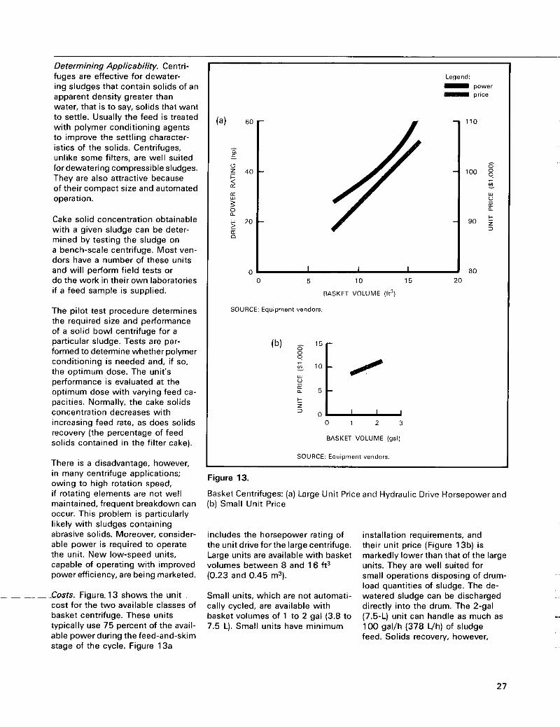
Determining Applicability. Centri- fuges are effective for dewater- ing sludges that contain solids of an apparent density greater than water, that is to say, solids that want to settle. Usually the feed is treated with polymer conditioning agents to improve the settling character- istics of the solids. Centrifuges, unlike some filters. are well suited for dewatering compressible sludges. They are also attractive because of their compact size and automated operation.
Cake solid concentration obtainable with a given sludge can be deter- mined by testing the sludge on a bench-scale centrifuge. Most ven- dors have a number of these units and will perform field tests or do the work in their own laboratories if a feed sample is supplied.
The pilot test procedure determines the required size and performance of a solid bowl centrifuge for a particular sludge. Tests are per- formed to determine whether polymer conditioning is needed and, if so, the optimum dose. The unit's performance is evaluated a t the optimum dose with varying feed ca- pacities. Normally, the cake solids concentration decreases with increasing feed rate. as does solids recovery (the percentage of feed solids contained in the filter cake).
There is a disadvantaoe. however
Legend:
111 price - power
0 5 10 15 20
BASKET VOLUME (ft3)
SOURCE: Equipment vendors.
if rotating elements are not well maintained, frequent breakdown can occur. This problem is particularly likely with sludges containing abrasive solids. Moreover, consider- able power is required to operate the unit. New low-speed units, capable of operating with improved power efficiency, are being marketed.
Costs. Figure- 13 shows the unit cost for the two available classes of basket centrifuge. These units typically use 75 percent of the avail- able power during the feed-and-skim stage of the cycle. Figure 13a
t z 2 0
0 1 2 3
BASKET VOLUME (gal)
SOURCE: Equipment vendors I
owing to high rotation speed, Basket Centrifuges: (a) Large Unit Price and Hydraulic Drive Horsepower and (b) Small Unit Price
includes the horsepower rating of the unit drive forthe large centrifuge. Large units are available with basket volumes between 8 and 1 6 ft3 (0.23 and 0.45 m3).
Small units, which are not automati- cally cycled, are available with basket volumes of 1 to 2 gal (3.8 to 7.5 LI. Small units have minimum
installation requirements, and their unit price (Figure 13b) is markedly lower than that of the large units. They are well suited for small operations disposing of drum- load quantities of sludge. The de- watered sludge can be discharged directly into the drum. The 2-gal (7.5-L) unit can handle as much as 100 gal/h (378 Vh) of sludge feed. Solids recovery, however,
27
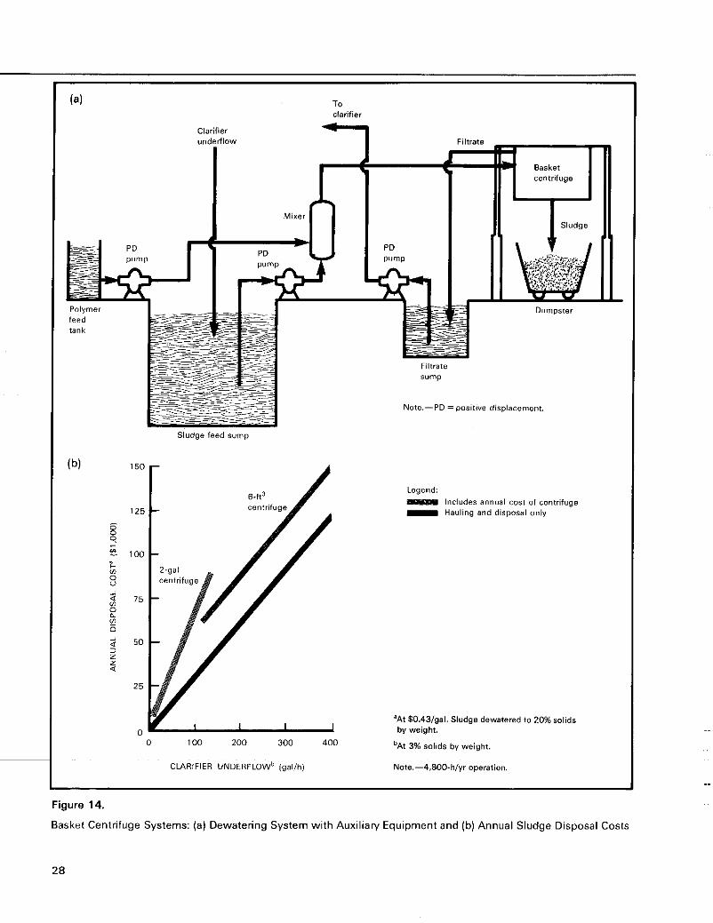
. . ..
Od--'alON
duns LBllllj
dund Od
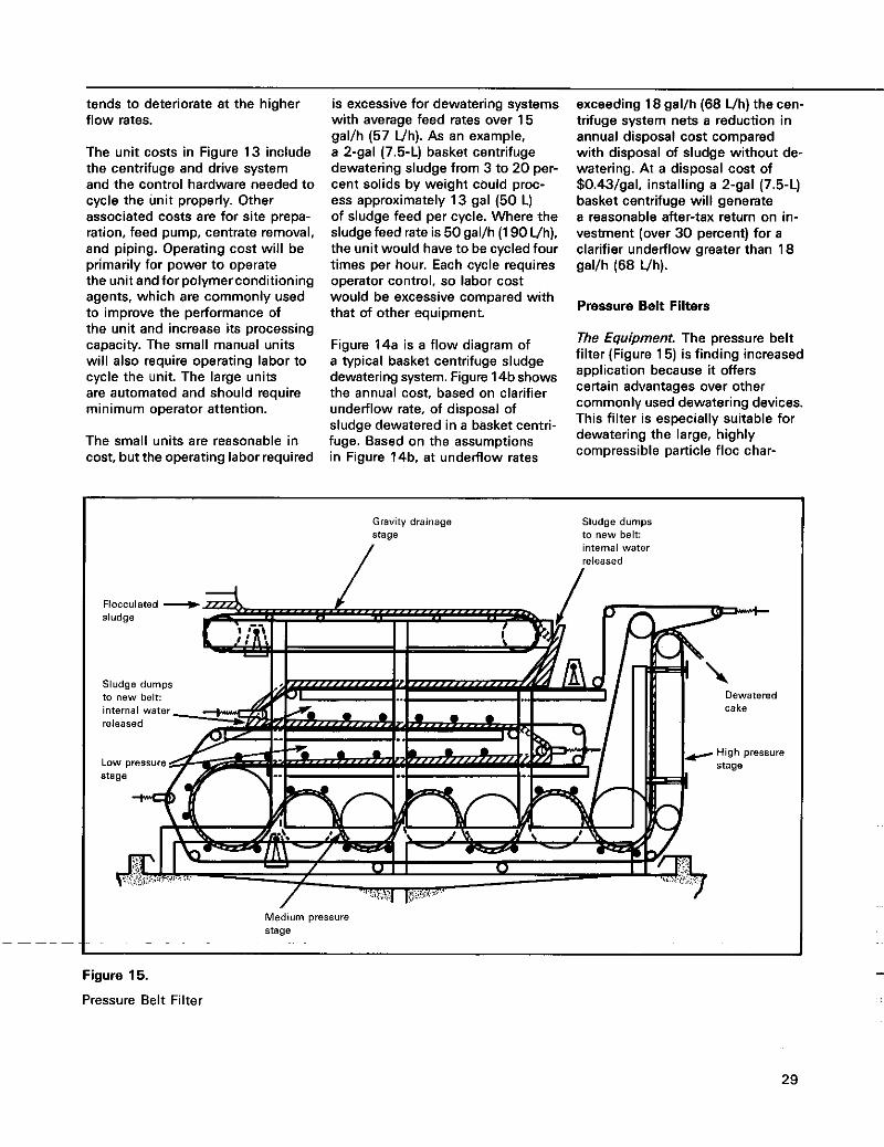
tends to deteriorate at the higher flow rates.
The unit costs in Figure 13 include the centrifuge and drive system and the control hardware needed to cycle the unit properly. Other associated costs are for site prepa- ration, feed pump, centrate removal, and piping. Operating cost will be primarily for power to operate the unit and tor polymerconditioning agents, which are commonly used to improve the performance of the unit and increase its processing capacity. The small manual units will also require operating labor to cycle the unit. The large units are automated and should require minimum operator attention.
The small units are reasonable in cost, but the operating labor required
is excessive for dewatering systems with average feed rates over 15 gal/h (57 Vh). As an example, a 2-gal (7.5-L) basket centrifuge dewatering sludge from 3 to 20 per- cent solids by weight could proc- ess approximately 13 gal (50 L) of sludge feed per cycle. Where the sludge feed rate is 50 gal/h (1 90 Vh), the unit would have to be cycled four times per hour. Each cycle requires operator control, so labor cost would be excessive compared with that of other equipment.
Figure 14a is a flow diagram of a typical basket centrifuge sludge dewatering system. Figure 14bshows the annual cost, based on clarifier underflow rate, of disposal of sludge dewatered in a basket centri- fuge. Based on the assumptions in Figure 14b. at underflow rates
exceeding 18 gal/h (68 Uh) the cen- trifuge system nets a reduction in annual disposal cost compared with disposal of sludge without de- watering. At a disposal cost of $0.43/gal, installing a 2-gal (7.5-L) basket centrifuge will generate a reasonable after-tax return on in- vestment (over 30 percent) for a clarifier underflow greater than 18 gal/h (68 Vh).
Pressure Belt Filters
The Equipment. The pressure belt filter (Figure 15) is finding increased application because it offers certain advantages over other commonly used dewatering devices. This filter is especially suitable for dewatering the large, highly compressible particle floc char-
Gravity drainage stage
/ Sludge dumps to new belt: internal water released
/ Flocculated +
Sludge dumps to new belt: Dewatered internal water
Medium pressure stage
Figure 15.
Pressure Belt Filter
29
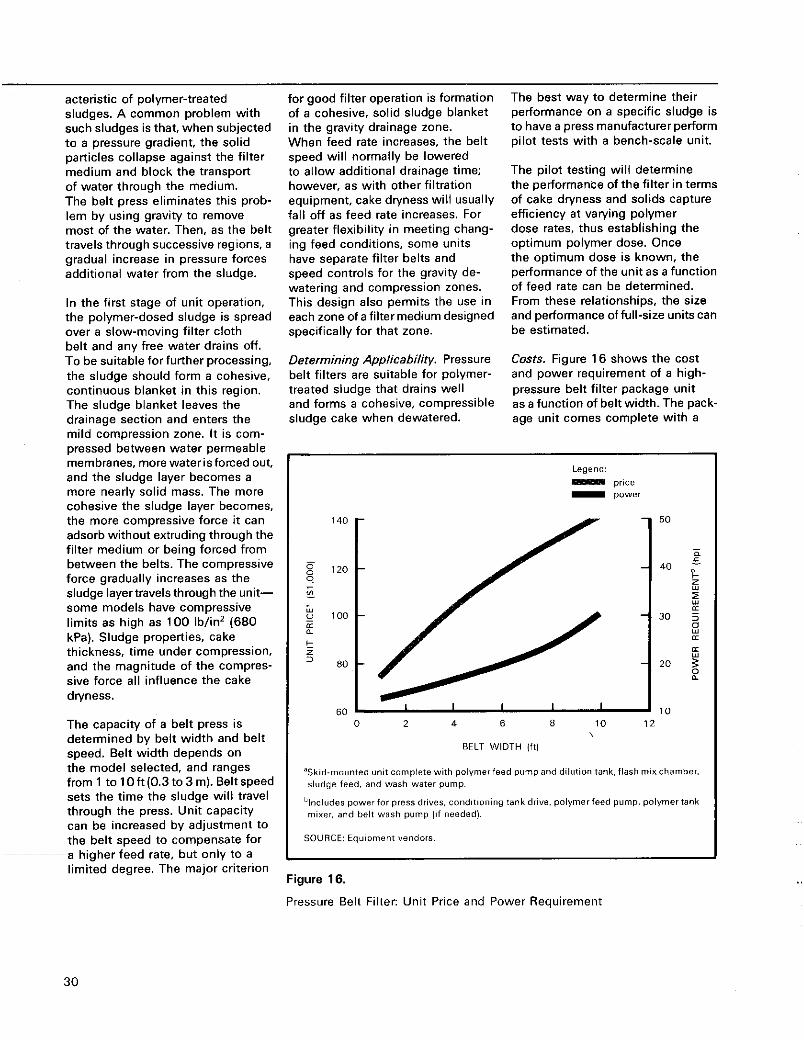
acteristic of polymer-treated sludges. A common problem with such sludges is that, when subjected to a pressure gradient, the solid particles collapse against the filter medium and block the transport of water through the medium. The belt press eliminates this prob- lem by using gravity to remove most of the water. Then, as the belt travels through successive regions, a gradual increase in pressure forces additional water from the sludge.
In the first stage of unit operation, the polymer-dosed sludge is spread over a slow-moving filter cloth belt and any free water drains off. To be suitable for further processing, the sludge should form a cohesive, continuous blanket in this region. The sludge blanket leaves the drainage section and enters the mild compression zone. It is com- pressed between water permeable membranes, more waterisforced out, and the sludge layer becomes a more nearly solid mass. The more cohesive the sludge layer becomes, the more compressive force it can adsorb without extruding through the filter medium or being forced from between the belts. The compressive force gradually increases as the sludge layertravels through the unit- some models have compressive limits as high as 100 Ib/in2 (680 kPa). Sludge properties, cake thickness, time under compression, and the magnitude of the compres- sive force al l influence the cake dlyness.
The capacity of a belt press is determined by belt width and belt speed. Belt width depends on the model selected, and ranges from 1 tolOft(0.3to3m).Beltspeed sets the time the sludge will travel through the press. Unit capacity can be increased by adjustment to the belt speed to compensate for a higher feed rate, but only to a limited degree. The major criterion
for good filter operation is formation of a cohesive, solid sludge blanket in the gravity drainage zone. When feed rate increases, the belt speed will normally be lowered to allow additional drainage time; however, as with other filtration equipment, cake dryness will usually fall off as feed rate increases. For greater flexibility in meeting chang- ing feed conditions, some units have separate filter belts and speed controls for the gravity de- watering and compression zones. This design also permits the use in each zone of a filter medium designed specifically for that zone.
Determining Applicability. Pressure belt filters are suitable for polymer- treated sludge that drains well and forms a cohesive, compressible sludge cake when dewatered.
The best way to determine their performance on a specific sludge is to have a press manufacturer perform pilot tests with a bench-scale unit.
The pilot testing will determine the performance of the filter in terms of cake dryness and solids capture efficiency a t varying polymer dose rates, thus establishing the optimum polymer dose. Once the optimum dose is known, the performance of the unit as a function of feed rate can be determined. From these relationships, the size and performance of full-size units can be estimated.
Costs. Figure 16 shows the cost and power requirement of a high- pressure belt filter package unit as a function of belt width. The pack- age unit comes complete with a
140
120 9 'A -
100 n a k z 3 E0
E"
Legend: - power pr,ce
1 2 10 I"
0 2 4 6 8
BELT WIDTH (it)
'Skid-mounted unit complete with polymerfeed pumpand dilution tank,flash mixchamber,
%eludes power for press drives, conditioning tank drive. polymer feed pump, polymer tank
sludge feed. and wash water pump.
mixer. and bell wash pump (If needed).
SOURCE: Equipment vendors.
Figure 16.
Pressure Belt Filter: Unit Price and Power Requirement
30
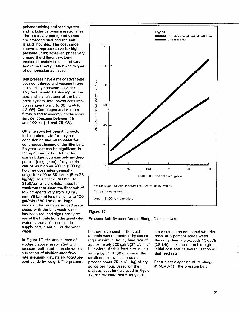
polymer-mixing and feed system, and includes belt-washing auxiliaries. The necessaly piping and valves are preassembled and the unit is skid mounted. The cost range shown is representative for high- pressure units; however, prices vary among the different systems marketed, mainly because of varia- tion in belt configuration and degree of compression achieved.
Belt presses have a major advantage over centrifuges and vacuum filters in that they consume consider- ably less power. Depending on the size and manufacturer of the belt press system, total power consump- tion ranges from 5 to 30 hp (4 to 22 kW). Centrifuges and vacuum filters, sized to accomplish the same service, consume between 15 and lo0 hp (1 1 and 75 kW).
Other associated operating costs include chemicals for polymer conditioning and wash water for continuous cleaning of the filter belt. Polymer cost can be significant in the operation of belt filters; for some sludges, optimum polymer dose per ton (megagram) of dry solids can be as high as 200 Ib (100 kg). Polymer dose rates generally range from 10 to 50 Iblton (5 to 25 kg/Mg), at a cost of $30/ton to $1 50Iton of dry solids. Rates for wash water to clean the filter belt of fouling agents valy from 10 gal/ min (38 Umin) for small units to 100 gallmin (380 Vmin) for larger models. The wastewater load asso- ciated with the belt wash water has been reduced significantly by use of the filtrate from the gravity de- watering zone of the press to supply part, if not all, of the wash water.
In Figure 17, the annual cost of sludge disposal associated with pressure belt filtration is shown as a function of clarifier underflow
-rate, assuming dewatering to 20 per- cent solids by weight. The pressure
Legend: includes annual cost of bell filter - disposal only
12(
1 O(
F
s 0 0 8C - F vi s 2 2 6C
E 0 i Q 2 z 40 z Q
vi
20
0 0 50 100 150 200 250
CLARIFIER UNDERFLOWb (gal/h)
"At 50,43/gal. Sludge dewatered 10 20% solids by weight.
'At 3% solids by weight.
Note.-4.8OO-h/yr operation.
Figure 17.
Pressure Belt System: Annual Sludge Disposal Cost
belt unit size used in the cost analysis was determined by assum- ing a maximum hourly feed rate of approximately300 gallft (37 Vcm) of belt width. At this feed rate, a unit with a belt 1 ft (30 cm) wide (the smallest size available) could process about 75 Ib (34 kg) of dry solids per hour. Based on the disposal cost formula used in Figure 17, the pressure belt filter yields
a cost reduction compared with dis- posal a t 3 percent solids when the underflow rate exceeds 10 gal/h (38 Vh)-despite the unit's high initial cost and its low utilization a t that feed rate.
For a plant disposing of its sludge at $0.43/gal, the pressure belt
31
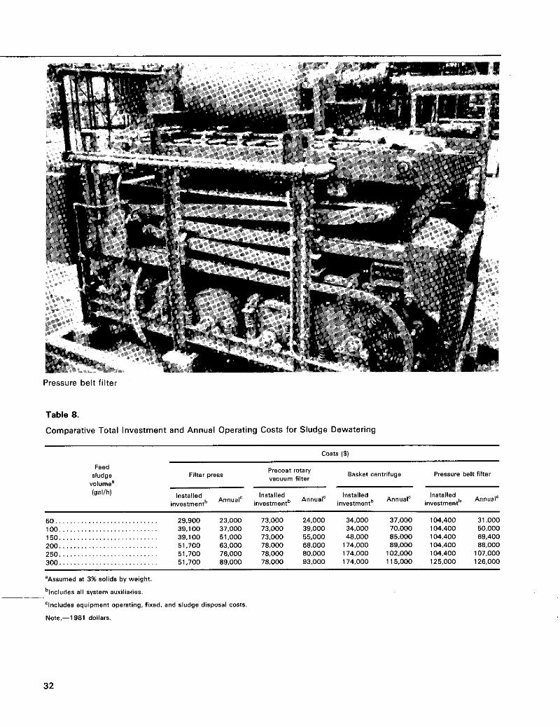
Pressure belt filter
Table 8.
Comparative Total Investment and Annual Operating Costs for Sludge Dewatering
sludge Filter press Basket centrifuge Pressure belt filter PrecOat r o t q Feed
w w u m filter volume'
IgalIh) Installed Installed ln$tslled Installed Annual' investmentb
AnnualC investmentb Annual' investmenth Annual'
inwstmentb
50 ............................ 29.900 23,000 73.000 24.000 34.000 37.000 104,400 31,000 100 . . . . . . . . . . . . . . . . . . . . . . . . . . . 39.100 37.000 73.000 39,000 34.000 70.000 104.400 50,000 150 ........................... 39.100 51.000 73.000 55.000 48.000 85.000 104,400 69.400 200 . . . . . . . . . . . . . . . . . . . . . . . . . . . 51.700 63.000 78,000 68.000 174,000 89,000 104,400 88,000 250 ........................... 51.700 76.000 78.000 80,000 174,000 102.000 104.400 107,000 300 ........................... 51.700 89,000 78.000 93,000 174,000 115.000 125.000 126.000
'Assumed at 3% solids by weight.
blncludes 811 system auxiliaries.
'Includes equipment operating. fixed. and sludge disposal costs.
Note.-1 981 dollars.
32
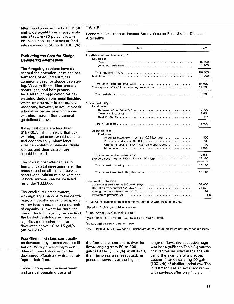
filter installation with a belt 1 ft (30 cm) wide would have a reasonable rate of return (30 percent return on investment after taxes) at feed rates exceeding 50 gal/h (190 4h).
Evaluating the Cost for Sludge Dewatering Alternatives
The foregoing sections have de- scribed the operation, cost, and per- formance of equipment types commonly used for sludge dewater- ing. Vacuum filters. filter presses, centrifuges, and belt presses have all found application for de- watering sludge from metal finishing waste treatment. It is not usually necessary. however, to evaluate each alternative before selecting a de- watering system. Some general guidelines follow.
If disposal costs are less than $1 5,00O/yr, it is unlikely that de- watering equipment would be justi- fied economically. Many landfill sites can solidify or dewater dilute sludge, and their capabilities should be used.
The lowest cost alternatives in terms of capital investment are filter presses and small manual basket centrifuges. Minimum size versions of both systems can be installed for under $30,000.
The small filter press system, although equal in cost to the centri- fuge, will usually have more capacity. At low feed rates, the cost per unit of capacity is lowest for the filter press. The low capacity per cycle of the basket centrifuge will require significant operating labor a t flow rates above 10 to 15 gal/h (38 to 57 Uh).
Poor-filtering sludges can usually be dewatered by precoat vacuum fil- tration. With polyelectrolyte con- ~ditioning, most sludges can be dewatered effectively with a centri- fuge or belt filter.
Table 8 compares the investment and annual operating costs of
Table 9.
Economic Evaluation of Precoat Rotary Vacuum Filter Sludge Disposal Alternative
Item cost
Installation of modifications (51:’ Equipment:
Filte . . . . . . . . . . . . . . . . . . . . . . . . . . . . . . . . . . . . . . . . . . . . . . . . . . . . . . . . . . . . . . . . . . . . . . . . . . . . . . . . . . . . . . . . . . . . . . . . . .
. . . . . . . . . . . . . . . . . . . . . . . . . . . . . . . . . .
. . . . . . . . . . . . . . . . . . . . . . . . . . . . . . . . . .
Total cost including installation . . . . . . . . . . . . . . . . . . . . . . . . . . . . . . . . . . . . Contingency. 20% of total including installation.. .......................
Tots1 installed cost . . . .
Annual Costs (5/yr):b Fixed costs:
Depreciation on equipment Taxes and inSuranCe . . . . . . . . . . . . . . . . . . . . . . . . . . . . . . . . . . . . . . . . . . . . COSt Of capital . . . . . . . . . . . . . . . . . . . . . . . . . . . . . . . . . . . . . . . . . . . . . . . . .
Total fixed costs
Operating cost: Equipment:‘
Power a t 50.05lkWh (10 hp a t 0.75 LWhIhp) . . . . . . . Precoat chemicals st 50.10llb ............................... Operating labor. a t 510lh (0.5 h/8 h operation). . . . . . . . . . . . . . . . . Maintenance . . . . . . . . . . . . . . . . . . . . . . . . . . . . .
45,000 11,500
56.500 4,500
-
- - 61,000 12,200
73.200
- - -
7,300 1,600
NA
8.900
- - -
500 700 700
1.000
Total equipment operating cost . . . . . . . . . . . . . . . . . . . . . . . . . . . . . . . . . . . . 2,900 12.380
15.280
Sludge disposal fee. a t 25% solids and 50.43lgal.. .....................
Total annual operating cost.. . . . . . . . . . . . . . . . . . . . . . . . . . . . . . . . . . . . . . . - -
Total annual cost including fixed cost. . ............................. 24.180
Investment jwtificstion: Current disposal cost a t 3% solids (5 ly r ) . . . . . . . . . . . . . . . . . . . . . . . . . . . . . . . Reduction from current cost (5lyr) . . . . . . . . . . . . . . . . . . . . . . . . . . . . . . . . . . . .
103,000 78.820
59 ~ v e r a g e return on investment I % ) ~ . . . . . . . . . . . . . . . . . . . . . . . . . . . . . . . . . . . . InveStment payback (yr)’ . . . . . . . . . . . . . . . . . . . . . . . . . . . . . . . . . . . . . . . . . . . . 1.5
’Elevated installation of precost rotmy vacuum filter with 19-ft2 filter area
’Based on 1,050 h/yr of filter operation.
‘4,800 h/yr and 22% operating factor.
‘(578.820 X 0.55)/$73,200 (0.55 based on a 45% tax ratel.
8573.200/[(578.S20 X 0.55) + 7.3001.
Note.-l981 dollars. Dewatering 50 gallh from 3% to 20% solids by weight. NA = not applicable.
the four equipment alternatives for flows ranging from 50 to 300 gal/h (1 90 to 1.1 35 Uh). At all levels, the filter press was least costly in general; however, a t the higher
range of flows the cost advantage was less significant. Table 9 gives the cost factors included in the analysis, using the example of a precoat vacuum filter dewatering 50 gallh (1 90 Vh) of clarifier underflow. The investment had an excellent return, with payback after only 1.5 yr.
33
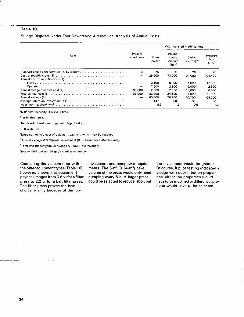
............................................ 2'2 6'0 5' 1 9'0 - ,(>A) yooqAed ~UB~ISBAUI
.................................... 11%) luauIsan"! "0 ","la, afismv -
................................................. (5) ssqnss 1e"""V 000' 1 E 000'LE OOl't,Z 000'EZ 000'EOl (5) ISO~ len~ue le101
005'2 .OOb'9 1 006'2 009'1 - 005'2 1 OOO't, 006'8 OOL'E -
OObPOl 000'PE OOZ'EL 006'62 - 02 02 52 52 E
9E L6 65 Lbl 002'89 002'09 006'8L 000'08 -
000'9 I oo9,91 OOE,Z1 OOE,Z1 OOoEO1 (5) 1503 lesods!p a6pnl~ lenuuv ...................................... .................................................... emdo
............................. paw :($I SUO!lBJ!$!pOU $0 IS03 IenUtJV
............................................ (5) suo!ie3!&!pou &a is03
............................ (146!aM Aq %I UO!I~J~U~~UO~ sp!los Iesods!(I
References 'US. Environmental Pmtection Agency. "Hazardous Waste Man- agement System: Identification and Listing of Hazardous Wastes." Federal Register 45(98):33084- 331 33, May 19, 1980.
2National Association of Manufac- turers. Hazardous Waste Man- agement Under RCRA, A Primer for Small Business. Washington DC, NAM, Oct. 1980.
3Richard W. Crain. "Solids Removal and Concentration." In US. Environmental Protection Agency and American Electroplaters' Society (cosponsors), Third Con- ference on Advanced Pollution Control for the Metal Finishing In-
Feb. 1981. dustry. EPA 600/2-81-028.
'+US. Environmental Protection Agency. "Hazardous Waste Man- agement System: Standards for Generators of Hazardous Waste." Federal Register 45(98):33140- 331 48, May 19. 1980.
5U.S. Environmental Protection Agency. "Hazardous Waste Man- agement System: Standards for Transporters of Hazardous Waste." Federal Register 45(98):33150- 331 52. May 19. 1980.
BUS. Environmental Protection Agency. "Hazardous Waste Man- agement System: Standards for Owners and Operators of Hazardous Waste Treatment, Storage, and Disposal Facilities." Federal Reg- ister 45(98):33154-33258. May 19. 1980.
7U.S. Department of Transportation. "Transport of Hazardous Wastes and Hazardous Substances." Federal Register 45( 101 ):34560- 34705, May 22. 1980.
8U.S. Environmental Protection Agency. "Hazardous Waste Man- agement System: Suspension of Rules and Proposal of Special Standards for Wastewater Treat- ment Tanks and Neutralization Tanks." Federal Register 45(223): 76074-76083, Nov. 17, 1980.
9U.S. Environmental Protection Agency. "Hazardous Waste Man- agement System: Proposal to Modify 40CFR Part 265-Sub- part H-Financial Requirements.'' Federal Register 45(98):33260- 33278, May 19. 1980.
'ONational Paint and Coatings Association. Hazardous Waste Treatment and Disposal Facilities. Environmental Bulletin. Wash- ington DC. NPCA, Feb. 1980.
l1 US. Environmental Protection Agency. Information About Haz- ardous Waste Management Facilities. NTlS No. PB 274881. July 1975.
12Roy, Clarence. "Methods and Technologies for Reducing the Generation of Electroplating Sludges." In US. Environmental Protection Agency and American Electroplaters' Society (co- sponsors), Second Conference on Advanced Pollution Control for the Metal Finishing Industry. EPA
297453. Feb. 1979. 600/8-79-014. NTlS NO. PB
13Steward, F. A,, and Leslie E. Lancy. "Minimizing the Generation of Metal-Containing ?Vaste Sludges." In US. Environmental Protection Agency and American Electro- platers' Society (cosponsors), First Annual Conference on Advanced Po~lution Control for the Met8l Finishing Industry. NTlS No. PB 282443. Jan. 1978.
''U.S. Environmental Protection Agency. Environmental Pollution Control Alternatives: Economics of Wastewater Treatment Alter- natives for the Electroplating lndus-
June 1979. try. EPA 625/5-79-016.
'5U.S. Environmental Protection Agency. Contml and Treatment Technology for the Metal Finishing Industry: Sulfide Precipitation. EPA 625/8-80-003. Apr. 1980.
35
' W . S . Environmental Protection Agency. Control and Treatment Technology for the MeJal Finishing Industry: In-Plant Chinges. EPA 625/8-82-008. Jan. 1982.
"Kushner, Joseph E. Water and Waste Control forthe Plating Shop. Cincinnati OH, Gardner Publi- cations, 1976.
W . S . Environmental Protection Agency. In-Process Pollution Abatement: Upgrading Metal- Finishing Facilities to Reduce Pol- lotion. EPA 625/3-73-002. NTlS No. PB 260546. July 1973.
lSCrampton, Peter. "Sludge Handling and Disposal." Paper presented at US. Environmental Agency Seminar on Handling Electro- plating Wastes, Philadelphia PA, Sept. 30, 1980.
20Liptak. 6. G. (ed.) Environmental Engineers Handbook. Vol 1. Radnor PA, Chilton Book Co., 1974. P. 905.
36