environmental consulting & management roux …environmental consulting & management . roux...
TRANSCRIPT

ENVIRONMENTAL CONSULTING & MANAGEMENT
ROUX ASSOCIATES INC 12 Gill Street, Suite 4700 Woburn, Massachusetts 01801 TEL 781-569-4000 FAX 781-569-4001
November 18, 2014
Mr. David J. Newton NH/RI Superfund Section U.S. Environmental Protection Agency 5 Post Office Square, Suite 100 Mail Code OSRR07-1 Boston, Massachusetts 02109
Re: Proposed Plan for Operable Unit 2 Peterson/Puritan Superfund Site Cumberland/Lincoln, Rhode Island
Dear Mr. Newton:
On behalf of Teknor Apex Company (Teknor Apex), Roux Associates is submitting the following comments regarding the Proposed Plan for Operable Unit 2 (OU2) of the Peterson/Puritan Superfund Site in Cumberland and Lincoln, Rhode Island (Site). As you are aware, Teknor Apex has been named as a potentially responsible party (PRP) for OU2 of the Site; further, Teknor Apex is a member of the Joint Defense Group for OU2 and expects to be one of the performing parties likely to enter into an agreement with the U.S. Environmental Protection Agency (EPA) for cleanup of OU2. Consequently, Teknor Apex has a significant interest in the selection of a remedy for OU2 that provides adequate protection to human health and the environment yet does so in a manner and at a cost commensurate with actual risks. In this regard, Teknor Apex has contributed to and approved the comments on the Proposed Plan prepared on behalf of the Joint Defense Group by Woodard & Curran and submitted to EPA on November 4, 2014. However, because Teknor Apex was not a signatory to the agreement with EPA for performance of the remedial investigation (RI) and feasibility study (FS)—and thus was not a performing party for the RI and FS—it has therefore authorized Roux Associates to provide independent comments on behalf of Teknor Apex alone, dealing specifically with the FS and the portion of the Proposed Plan relating to containment of the waste in the J.M. Mills Landfill portion of OU2.
The comments being submitted by Roux Associates on behalf of Teknor Apex mirror, to a large degree, several of the comments being submitted on behalf of the Joint Defense Group. More specifically, as set forth in more detail below, we believe that the Proposed Plan is factually incorrect in places (and thus provides a misleading impression to the public) and that the selected alternative for capping of the J.M. Mills Landfill is (1) not sufficiently justified from both technical and regulatory perspectives and (2) more conservative than necessary to address the level of risk at the Site (and thus unnecessarily destructive to the environment). But furthermore, we believe that the FS (which served as the basis for the Proposed Plan) overlooked a third option for capping of the J.M. Mills Landfill, i.e., in addition to the options included
2006.0001M002.100/L
Mr. David J. Newton November 18, 2014 Page 2
in Alternatives JM-SO-2 (RCRA Subtitle C Cap of Whole Landfill) and JM-SO-3 (Combination RCRA Subtitle C Cap [top]/Perimeter Soil Cap [side slopes], also referred to as “The Hybrid Cap”).1 More specifically, we are of the opinion that an alternative featuring an evapotranspiration (ET) cap should also have been considered and subjected to detailed evaluation during the FS and, in any event, should be considered at this time. To address this omission in the FS—but by no means detracting from the merits of the Joint Defense Group’s arguments for the Hybrid Cap—Roux Associates has included within its comments being submitted on behalf of Teknor Apex both general and site-specific information supporting selection of an ET cap as an alternative approach for capping of the J.M. Mills Landfill. As demonstrated herein, an ET cap would meet all of the remedial action objectives for the J.M. Mills Landfill and provide the necessary protectiveness without the adverse impacts to aesthetics that would come with a conventional RCRA Subtitle C cap; it would also result in less truck traffic in the community, would require less long-term maintenance, and would have a much smaller carbon footprint than a RCRA Subtitle C cap. In fact, as an ET cap would provide even greater—although not necessarily warranted—protection against infiltration and potential leachate generation compared to the Hybrid Cap and, at the same time, would result in less impact to the surrounding community and less longterm loss of riverbank and upland habitat relative to the RCRA Subtitle C cap, we believe an ET cap provides EPA with a reasonable compromise between the two remedial alternatives for the J.M. Mills Landfill currently “on the table,” thus better balancing regulatory requirements and public concern.
Comments Regarding Proposed Plan
1. The Proposed Plan is factually incorrect in places and is thus misleading to the public. More specifically, the Proposed Plan incorrectly states in multiple places (including but not limited to pages 1, 7, 10, and 27) that hazardous waste was disposed of in the J.M. Mills Landfill. On the contrary, by (1) indicating in meetings and discussions with the performing parties for the FS that the Resource Conservation Recovery Act (RCRA) Subtitle C requirements for the treatment, storage, and disposal of hazardous waste (40 CFR Part 264) are not “applicable” for cleanup of the J.M. Mills Landfill, (2) indicating in the FS report (Section 7.2.1.2.2) that “relevant and appropriate hazardous waste landfill closure standards will be the primary standards used to design, construct and maintain the landfill cap,” and (3) indicating in the FS report tables (e.g., Table I-5b) that certain RCRA Subtitle C and analogous state regulations are “relevant and appropriate,” rather than “applicable,” EPA has, in effect, acknowledged that hazardous waste was not disposed of in the J.M. Mills Landfill (or that insufficient evidence exists to make an affirmative determination that hazardous waste was disposed of in the J.M. Mills Landfill). This distinction is important because it means that the cap for the J.M. Mills Landfill does not necessarily have to meet all RCRA Subtitle C landfill closure requirements (40 CFR 264.310), only those that are “relevant and appropriate.” This point is discussed further in comment #3 below.
We have excluded the No Action Alternative (JM-SO-1) from this discussion.
ROUX ASSOCIATES, INC. 2006.0001M002.100/L
1

Mr. David J. Newton November 18, 2014 Page 3
2. The selected alternative for capping of the J.M. Mills Landfill (JM-SO-2) is not sufficiently justified from a technical perspective. In the Proposed Plan, EPA claims that Alternative JM-SO-2, which includes a full RCRA Subtitle C cap for the J.M. Mills Landfill, is the only alternative that will be fully protective of human health and the environment and that, conversely, Alternative JM-SO-3 (which includes the Hybrid Cap) is not fully protective because “it does not establish a completely protective physical barrier between potential receptors and contaminated materials in soil and waste, does not fully reduce the infiltration and the potential for leaching of contaminants in soil to groundwater, does not fully address potential landfill gas releases, and does not ensure that contamination is not eroded or washed out of the J.M. Mills Landfill during any flood, up to a 500-year event.” However, nowhere does EPA adequately support their claim that the Hybrid Cap is not fully protective, either in the Proposed Plan or the FS report:
• With regard to EPA’s contention that Alternative JM-SO-3 does not establish a completely protective physical barrier between potential receptors and contaminated materials in soil and waste, EPA does not clearly indicate how the Hybrid Cap is not a completely protective barrier. For example, Section 6.2.1.3 of the FS report states that “[Alternative JM-SO-3] provides protection to human health by preventing or controlling potential exposures to waste and contaminated soils through . . . installation of a RCRA Subtitle C Cap on the upper one-third of the J.M. Mills Landfill and a perimeter soil cap over the lower two-thirds of the J.M. Mills Landfill.” However, without any basis provided, Table 6-7 of the FS report indicates that Alternative JM-SO-3 “would not fully prevent exposure to receptor[s] in the soil cap area” and “would not be effective in preventing exposure to receptors in the soil cap area.” Similarly, Section 7.2.1.3.1 of the FS report states, again without basis or explanation, “The installation of the hybrid landfill cap . . . will place a limited physical barrier between potential receptors and contaminated materials in soil and waste to reduce the potential exposure pathway” (emphasis added). On the contrary, there is nothing “limited” about the hybrid cap when it comes to preventing exposure to the waste and contaminated soil in the J.M. Mills Landfill. In fact, soil caps similar to that included in Alternative JM-SO-3 are routinely used by EPA and state environmental agencies such as the Rhode Island Department of Environmental Management (RIDEM) to cap landfills and other areas where exposure to waste and contaminated soil must be eliminated.
In searching the FS report for the basis of EPA’s assertion that the Hybrid Cap is not a completely protective barrier, we noted that in Section 7.2.1.3.3, the FS report states that Alternative JM-SO-3 may not eliminate the potential for direct contact with contaminants in soil/landfill debris by a receptor because the perimeter soil cap may not prevent the release of contaminants in the event of a flood or through the potential for erosion of the soil cap over the long term (emphasis added). If this in fact represents the basis for EPA’s claim that the Hybrid Cap is not a completely protective barrier, we must point out
ROUX ASSOCIATES, INC. 2006.0001M002.100/L

Mr. David J. Newton November 18, 2014 Page 4
several flaws with EPA’s logic. First, to state that a remedial alternative may not prevent something from occurring is not adequate justification for concluding that it will not prevent that something from occurring. Secondly, the eventualities raised by EPA (i.e., a flood event or erosion over time) are design considerations that are more appropriately taken into account during the Remedial Design stage, which follows selection of the remedy. In fact, this is recognized in the FS report; for example, in Section 5 (Development of Remedial Alternatives), the report provides almost identical language in this regard for both capping alternatives:
JM-SO-2 (Section 5.2.1.5): “Since the cap will be located within the floodplain, the cap will need to be designed to prevent any release of contaminants during flooding, up to a 500-year flood event” (emphasis added).
JM-SO-3 (Section 5.2.1.6): “Since the cap will be located within the floodplain, the cap would need to achieve standards requiring no release of contaminants during flooding, up to a 500-year flood event.”
And thirdly, it is inappropriate to eliminate an alternative during the FS stage based simply on a feature or characteristic that has not yet been designed. By raising these design-related issues (susceptibility to flooding and erosion over time) during the FS only in regard to Alternative JM-SO-3 and not to Alternative JM-SO-2, EPA introduced substantial bias into their remedy selection process. For example, EPA conveniently assumed that a full RCRA Subtitle C cap (JM-SO-2) would be adequately designed to address flooding concerns (see Section 7.2.1.2.1 of the FS report) but did not make a similar assumption in its evaluation of the Hybrid Cap (JM-SO-3). There is no reason to believe that either cap could not be designed to adequately withstand episodic flooding and long-term erosion. Therefore, in this regard, the two caps (JM-SO-2 and JM-SO-3) are equivalent in terms of protectiveness and longevity at the FS stage.
• With regard to EPA’s contention that Alternative JM-SO-3 does not fully reduce the infiltration and the potential for leaching of contaminants in soil to groundwater, this point is not disputed. However, this distinction between the two capping alternatives is not material because the modeled difference in infiltration allowed by the two alternatives is only roughly 20% and there is no need to reduce infiltration at the Site to the degree typically associated with a full RCRA Subtitle C cap (i.e., 99%). More specifically, as evidenced by Site data and as recognized by EPA (e.g., during a December 2012 public meeting at the Cumberland Library), most detections of Site contaminants in groundwater were “scattered” and “not significant” and there is no well-defined plume. This is of great importance when one considers that the J.M. Mills Landfill has been inactive and uncapped for over 30 years. Not surprisingly, EPA has proposed no remediation of Site groundwater in its
ROUX ASSOCIATES, INC. 2006.0001M002.100/L

Mr. David J. Newton November 18, 2014 Page 5
Proposed Plan. The absence of any significant groundwater contamination (i.e., requiring remediation) in the vicinity of the J.M. Mills Landfill indicates either that the waste in the J.M. Mills Landfill does not contain significant quantities of hazardous substances and/or that leaching of such substances to groundwater is not occurring to any great extent. Therefore, the additional infiltration protection offered by the full RCRA Subtitle C cap is not necessary for the J.M. Mills Landfill, especially at an additional cost of almost $8 million.
• With regard to EPA’s contention that Alternative JM-SO-3 does not fully address potential landfill gas releases, this too—like the flooding concern discussed earlier—is a detailed design consideration, one that was appropriately not included in the conceptual design for Alternative JM-SO-3 evaluated during the FS. In fact, it is not clear at this point whether landfill gas emissions are even a concern for the J.M. Mills Landfill. For example, the Executive Summary of the FS report states, “Data collected from air emissions at the vents at the J.M. Mills Landfill suggest that there is some evidence of landfill gas generation that will be evaluated during remedial design” (emphasis added). Section 2.4.3.6 of the FS report similarly states, “During predesign studies, additional investigations will be conducted to ascertain whether landfill gases require remediation” (emphasis added). So landfill gas collection should not have been included as a remedial action objective (RAO) in the first place. It is reasonable to assume that it was included as an RAO for the J.M. Mills Landfill simply because landfill gas collection is typically needed whenever a RCRA Subtitle C cap is used (because the impermeable liner component of the RCRA Subtitle C cap typically traps and accumulates landfill gases), and both caps evaluated during the FS included RCRA Subtitle C caps.
As with the flooding concern, if landfill gas is determined to be an actionable issue for the J.M. Mills Landfill during the design stage, JM-SO-3 can be constructed with a gas venting layer or a passive trench network under the RCRA Subtitle C cap portion of the Hybrid Cap to permit collection and venting of landfill gases. For the unlined portion of the Hybrid Cap (the soil cap), landfill gas collection can be addressed in a similar fashion, as has been done at landfills with soil caps nationwide. Alternatively, if pre-design surface emissions monitoring identified an isolated landfill gas hot-spot (as seems to be the case based on the RI), it could be addressed with a simple vapor extraction system, rather than a traditional landfill gas recovery system. Thus it is inappropriate to characterize the Hybrid Cap as “not fully address[ing] potential landfill gas releases,” as EPA has.
ROUX ASSOCIATES, INC. 2006.0001M002.100/L

Mr. David J. Newton November 18, 2014 Page 6
• Finally, with regard to EPA’s contention that Alternative JM-SO-3 does not ensure that contamination is not eroded or washed out of the J.M. Mills Landfill during any flood, up to a 500-year event, this too is a design consideration to be addressed during the Remedial Design stage. As discussed already, EPA expressed concern that the perimeter soil cap component of the Hybrid Cap may not prevent the release of contaminants in the event of a flood (emphasis added), but arbitrarily and capriciously assumed that the full RCRA Subtitle C cap would prevent such a release. Without more detailed information regarding the design of the RCRA Subtitle C cap, such a conclusion is unsubstantiated. As stated once before, there is no reason to believe that either cap could not be designed to adequately withstand episodic flooding; therefore, the two caps (JM-SO-2 and JM-SO-3) are equivalent in terms of protectiveness against flooding and re-release of contained waste/contaminated soil.
3. The selected alternative for capping of the J.M. Mills Landfill (JM-SO-2) is not sufficiently justified from a regulatory perspective. In the Proposed Plan, EPA also claims that Alternative JM-SO-2 is the only alternative that can be designed and implemented to comply with applicable state and federal ARARs (i.e., applicable or relevant and appropriate requirements). The basis for this claim is that, in EPA’s view, Alternative JM-SO-3 “may not prevent the release of contaminants in the event of a flood” (emphasis added), does not meet hazardous waste landfill closure standards throughout the entirety of the cap, and will not allow for landfill gas control standards to be achieved. We have already addressed the EPA’s contentions about possible release of contaminants due to flooding and landfill gas control; consequently the focus for the remainder of this comment will be on EPA’s contention that Alternative JM-SO-3 (the Hybrid Cap) does not meet hazardous waste landfill closure standards throughout the entirety of the cap. Although not stated anywhere in the FS report or Proposed Plan, it is reasonable to assume that the “hazardous waste landfill closure standard” that EPA believes will not be met throughout the entirety of the Hybrid Cap is the RCRA Subtitle C requirement to “provide long-term minimization of migration of liquids through the closed landfill” (40 CFR 264.310(a)(1)). This assumption is based on EPA’s claim, discussed earlier in comment #2, that Alternative JM-SO-3 “does not fully reduce the infiltration and the potential for leaching of contaminants in soil to groundwater.” While this claim is accurate, as we have already discussed in comment #2, the additional infiltration protection offered by the full RCRA Subtitle C cap is not warranted for the J.M. Mills Landfill based on the existing groundwater conditions. For this reason, the RCRA Subtitle C requirement to provide long-term minimization of migration of liquids through the closed landfill is not a “relevant and appropriate” requirement for capping of the J.M. Mills Landfill. And as a result, since none of the RCRA Subtitle C requirements for the treatment, storage, and disposal of hazardous waste are “applicable” (as discussed in comment #2), Alternative JM-SO-3 does in fact meet hazardous waste landfill closure standards throughout the entirety of the cap (i.e., those that are relevant and appropriate, such as the requirement to promote drainage and minimize erosion or abrasion of the cover).
ROUX ASSOCIATES, INC. 2006.0001M002.100/L

Mr. David J. Newton November 18, 2014 Page 7
With respect to ARARs, although not specifically mentioned in the Proposed Plan, the FS report states that the Hybrid Cap does not comply with the Toxic Substances Control Act (TSCA). The FS report does not state why this is so, but it can reasonably be assumed based on language in Section 7.2.1.2.2 of the FS report (addressing Alternative JM-SO-2) and in the green highlight box on page 6 of the Proposed Plan that EPA’s contention that the Hybrid Cap does not comply with TSCA is based on the arbitrary assumption that any polychlorinated biphenyl (PCB)contaminated floodplain soils exceeding a concentration of 10 parts per million (ppm), which are to be excavated during implementation of the OU2 remedy, might be placed under the soil cap portion of the Hybrid Cap. Without conceding that the PCB-contaminated soil at the Site is, in fact, “PCB remediation waste” (as claimed in the Proposed Plan) or that the 10-ppm action level is appropriate given current and future Site uses (the action level is based on residential use), EPA’s assumption (as inferred per the foregoing) is completely groundless, as any PCB remediation waste exceeding 10 ppm that is identified during Site cleanup can simply be placed under the RCRA Subtitle C cap portion of the Hybrid Cap. This point notwithstanding, given the foregoing discussion regarding the non-relevance and non-appropriateness of the RCRA Subtitle C requirement to minimize migration of liquids (i.e., precipitation) through the landfill, it is not appropriate to link TSCA compliance to full compliance with RCRA Subtitle C. Similarly, the provisions of TSCA that relate to infiltration protection (e.g., the need for a low-permeability cap) for PCB remediation waste should likewise not apply to the J.M. Mills Landfill, especially considering the relatively low solubility of PCBs and the fact that PCB remediation waste at the concentrations found at the Site (maximum of 12 ppm) can be disposed of at a municipal solid waste landfill or non-municipal, non-hazardous waste landfill under other provisions of TSCA.
We wish to make one last point with regard to TSCA. The Proposed Plan indicates that EPA has made a draft finding that Alternative JM-SO-2 (full RCRA Subtitle C cap) will meet risk-based protectiveness requirements for the remediation of PCBs under TSCA, but it does not appear that EPA ever evaluated the ability of Alternative JM-SO-3 (Hybrid Cap) to do the same. To state that Alternative JM-SO-2 will meet risk-based protectiveness requirements for the remediation of PCBs under TSCA without having evaluated the protectiveness of JM-SO-3—thereby suggesting that only JM-SO-2 would meet TSCA requirements—is misleading and further introduces bias into the remedy selection process. By limiting TSCA review to Alternative JMSO-2, EPA acted arbitrarily and capriciously.
ROUX ASSOCIATES, INC. 2006.0001M002.100/L

Mr. David J. Newton November 18, 2014 Page 8
4. The selected alternative for capping of the J.M. Mills Landfill is more conservative than is necessary to address the level of risk at the Site and is thus unnecessarily destructive to the environment. EPA states in the Proposed Plan that Alternative JM-SO-2, the full RCRA Subtitle C cap, is the Least Environmentally Damaging Practicable Alternative (LEDPA), in that “it provides the best balance of addressing contaminated soil/debris within and adjacent to wetlands and waterways with minimizing both temporary and permanent alteration of wetlands and aquatic habitats on site.” This is simply not true. Rather, since Alternative JM-SO-3 is also practicable and, by virtue of certain inherent design aspects, is less damaging to wetlands and aquatic habitats at the Site, it is the LEDPA. More specifically, the side slopes of the full RCRA Subtitle C cap have a greater thickness than those for the Hybrid Cap and will possibly require terracing to ensure stability of the cap, meaning that the full RCRA Subtitle C cap would have a much larger lateral footprint than the Hybrid Cap. A larger footprint means greater encroachment into floodplains and wetlands compared to the Hybrid Cap. Also, given the greater thickness of the full RCRA Subtitle C cap slopes, the armoring structures needed to protect the toe of the slopes will likewise be larger, thereby taking away more flood storage volume than would be associated with the Hybrid Cap. The need for greater compensatory flood storage will result in further damage to wetlands elsewhere. Lastly, the lower volume of material required for the Hybrid Cap would also reduce the potential impact of the work on wetlands. These features all combine to make the Hybrid Cap the LEDPA.
ET Cap Alternative
An ET cap is being proposed herein as an alternative approach for capping of the J.M. Mills Landfill because it would not only meet all of the remedial action objectives for the J.M. Mills Landfill—even meeting the non-ARAR RCRA Subtitle C requirements regarding prevention of infiltration through the landfill—it would do so without the adverse impacts to aesthetics that will come with a conventional RCRA Subtitle C cap (or the EPA Region 1 alternative cap design). It would also result in less truck traffic in the community, would require less long-term maintenance, and would have a much smaller carbon footprint than a RCRA Subtitle C cap. General and site-specific information supporting selection of an ET cap as a viable option for capping of the J.M. Mills Landfill is provided below, including (1) relevant background information regarding ET caps, (2) a conceptual ET cap design for the J.M. Mills Landfill, and (3) a preliminary cover equivalency determination for the conceptual ET cap design.
1. Background
Like conventional landfill covers, ET caps provide for containment and isolation of waste (and thus elimination of exposure to human and ecological receptors) using layers of compacted and vegetated soil. However, unlike conventional covers that use low-permeability components (e.g., clay soil and synthetic liners) to also minimize the downward migration of water (precipitation and runoff) into the landfill, ET caps use water-balance components to minimize infiltration. More specifically, ET caps rely on the properties of soil to store water until it is either transpired through vegetation or
ROUX ASSOCIATES, INC. 2006.0001M002.100/L

Mr. David J. Newton November 18, 2014 Page 9
evaporated from the soil surface. Typically, an ET cap consists of a surface mulch layer and organic-rich topsoil, underlain by soils of varying composition and thickness. (The amount of water that can be stored in the soil cap depends on the type(s) and overall thickness of the soil.) Selected tree and grass species are then planted in the soil cap at densities designed to maximize uptake and consumption of the stored water through ET processes. These natural processes can be enhanced for wetter climates such as the northeast through the use of specialized vegetation to increase the uptake of water in soils by plant roots. Deep-rooting trees (such as hybrid poplars) can extend 4 to 6 feet or more below the land surface while establishing a dense root mass that takes up large quantities of water—on average between 10 and 20 gallons per day per tree during the growing season. The water consumption by the plants is the key factor in eliminating contaminant leachability and migration to groundwater.
In addition to minimizing infiltration, an ET cap will provide additional benefits that a conventional cover (such as the full RCRA Subtitle C cap) cannot. For example, by planting the deep-rooting trees directly into the waste, an ET cap can provide treatment of the waste through the processes of phytostabilization and rhizodegradation. Phytostabilization is the sequestering of inorganics (i.e., metals) in the rhizosphere (root zone) of selected plant species through adsorption onto the roots and precipitation within the root zone, which reduces the metals’ mobility, prevents their migration, and ultimately reduces their bioavailability. Rhizodegradation is the breakdown of organic contaminants in the soil through enhanced microbial activity in the rhizosphere. Plant roots increase microbial activity in soils via the release of root exudates (e.g., enzymes, sugars, amino acids, organic acids, fatty acids) and/or by increasing soil aeration and moderating soil moisture content, such that microbial populations and activities are 5 to 100 times greater in the rhizosphere than in bulk soil. To maximize these natural treatment processes, plant species for the ET cap will be selected based on their ability to quickly develop deep and extensive root systems, which will facilitate the transport of oxygen directly into the waste materials (and thus enhance in-situ biodegradation processes). Neither of the remedial alternatives currently “on the table” provides any treatment whatsoever, which runs counter to EPA’s statutory preference for remedial measures that provide treatment.
Another benefit that an ET cap will provide is a much smaller carbon footprint compared to a RCRA Subtitle C cap. Construction of an ET cap will produce fewer greenhouse gas emissions than would construction of a RCRA Subtitle C cap, and there is much less longterm care (e.g., mowing) associated with an ET cap compared to a RCRA Subtitle C cap (and so there will also be much less greenhouse gas emission associated with long-term care). But most importantly, the trees and woody plants used in the ET cap will remove carbon dioxide from the atmosphere and store the carbon within their biomass, thus sequestering large amounts of carbon from the atmosphere and resulting in a negative carbon footprint. Since the ET cap will be equally protective compared to the RCRA Subtitle C cap (explained below), use of this approach is consistent with EPA’s own Superfund Green Remediation Strategy and Green Remediation Best Management Practices for landfill cover systems.
ROUX ASSOCIATES, INC. 2006.0001M002.100/L
Mr. David J. Newton November 18, 2014 Page 10
Lastly, an ET cap would attenuate and treat stormwater runoff to the Blackstone River naturally. This would lessen the impact of stormwater on the already flood-prone river and would eliminate the need for space-consuming stormwater detention basins if such an approach were necessary. This is an important consideration in an area subject to frequent severe flooding and one without much room to spare for detention basins.
Given the foregoing, ET caps are among the most efficient and beneficial remedial alternatives available for managing the human and ecological risks associated with landfills. Their suitability and increasing use for landfill closures is well-documented in technical and regulatory guidance, including the following:
• Fact Sheet on Evapotranspiration Cover Systems for Waste Containment (EPA, 2011)
• (Draft) Technical Guidance for RCRA/CERCLA Final Covers (EPA, 2004)
• Technical and Regulatory Guidance for Design, Installation, and Monitoring of Alternative Final Landfill Covers (Interstate Technology & Regulatory Council, 2003)
• Technical Guidance on the Capping of Sites Undergoing Remediation (New Jersey Department of Environmental Protection, 2014)
Consistent with these guidance documents, Roux Associates and others have gained approval for and successfully installed ET caps at a number of Superfund and non-Superfund industrial-waste sites (including landfills) in the northeast part of the country, including the following:
• A former petroleum refinery in East Providence, Rhode Island
• A former industrial-waste landfill in Rensselaer, New York
• A former industrial-waste landfill in Rotterdam, New York
• The Bridgeport Rentals and Services (BROS) Superfund Site in Logan Township, New Jersey
• The Welsh Road Landfill Superfund Site in Honeybrook Township, Pennsylvania
• The Lower Darby Creek Area Superfund Site near Philadelphia, Pennsylvania
Examples of Roux Associates’ successful applications of ET caps are attached.
ROUX ASSOCIATES, INC. 2006.0001M002.100/L

Mr. David J. Newton November 18, 2014 Page 11
2. Conceptual ET Cap Design
The ET cap being proposed herein for the J.M. Mills Landfill entails more than just a different approach to covering and containing the landfill waste. It also includes unique slope/bank stabilization and stormwater management elements, which will contribute to the overall effectiveness of the ET cap. Each unique element of the design—the landfill cover, slope stabilization, and stormwater management—is described conceptually below.
Landfill Cover
The landfill cover will consist of a multi-layered soil blanket designed to eliminate the potential for both human and ecological receptors to come into direct contact with landfill materials. It will be vegetated with a diversity of native wildlife habitat-type species and phytotechnology plantings to minimize infiltration and leachate generation, reduce stormwater runoff, minimize erosion of the cover, permit treatment of the landfilled waste, and create ecological enhancements that would support and sustain indigenous and migratory wildlife species.
Soil Cover The soil cover will consist of three distinct layers, which will together provide for isolation of the waste and a stable environment for vegetation growth. The three layers include the following, from bottom to top, as shown in Figure 1:
• A 6-inch biota barrier
• A minimum 18-inch general fill layer
• A 6-inch topsoil layer
The 6-inch biota barrier will consist of recycled concrete aggregate (RCA) and will be installed immediately over the waste or cover soil (if and where existing) to isolate the waste materials from burrowing animals. At least 18 inches of common fill will be added over the biota barrier to provide a suitable barrier to prevent direct contact with the waste by humans. The 6-inch topsoil layer will be placed over the common fill layer to further isolate the waste and provide a rooting medium capable of providing mechanical support and anchoring of the specified vegetation. The combined soil layers (minimum of 24 inches, not including the biota barrier) are designed to provide temporary storage for infiltrating precipitation to minimize the amount of water migrating downward and into the waste material before it can be removed via ET.
ROUX ASSOCIATES, INC. 2006.0001M002.100/L

Mr. David J. Newton November 18, 2014 Page 12
Vegetation A high diversity and abundance of native trees and shrubs will be incorporated into the final planting plan for both the upper surface of the landfill as well as the side slopes (see Figure 1). Species to be planted will include a diversity of wildlife habitat-type species integrated with deep-rooting (i.e., expected to root deeply into the landfill waste) phytotechnology plantings (hybrid poplars and black willows) to facilitate ET as well as rhizodegradation to reduce residual organic constituents and phytostabilization mechanisms to sequester metals. These deep-rooted trees will not only consume water stored in the cap’s soil layers but will also—because they will be planted directly into the waste—remove large amounts of water from within the landfill waste itself. The vegetation planting density for the landfill cover will be designed to balance the water needs of the various plants with the precipitation management requirements of the cap. Further, in order to minimize translocation potentials, candidate vegetation species for use in the landfill cover will be screened for potential contaminant uptake using the EPA’s plant bioconcentration factor (BCF) protocol. This will enable the selection of appropriate plants with the lowest potential for translocation of contaminants into upper plant portions (e.g., trees/shrubs which do not produce fruit/seed for consumption) and, therefore, reduce the risk of translocation via wildlife ingestion and/or in leaf litter. The phytotechnology species to be selected also do not produce seed or fruit, thereby further reducing the potential for ecological exposure to contaminants and translocation of hazardous constituents via wind.
Erosion control will be achieved through the use of shrub plantings and native grass and wildflower seed for understory cover. The understory will provide immediate soil stabilization as the trees become established (over 3 to 5 years). Incorporation of the understory planting will additionally limit the potential for colonization by invasive plant species, yet still allow for introduction of the plants specified in the planting plan.
Slope/Bank Stabilization
Due to the steepness of the J.M. Mills Landfill and its location within a river floodplain, an important element of the ET cover design will be to provide additional slope and bank stabilization where needed. To improve resiliency of the cover and long-term containment of the landfill waste, the stabilization design will:
• Be self-sustaining (i.e., reduce requirements for human maintenance)
• Provide opportunities to connect fragmented habitat
• Preserve or enhance the existing bank
• Use native, non-invasive living materials (e.g., live willow stakes) where practicable
ROUX ASSOCIATES, INC. 2006.0001M002.100/L

Mr. David J. Newton November 18, 2014 Page 13
A variety of approaches are available to minimize the susceptibility of the cover to erosion. Protection generally consists of restoring and protecting banks against scour and erosion by using plantings, soil bioengineering, and structural systems. Preference should be given to those methods that restore the ecological functions and values of riverbank through the combination of hard (riprap revetment) and soft (vegetation) engineering practices. An example of a recent application of such measures at a coastal landfill site in New York is attached.
Armor Toe Protection Toe protection will be required to protect the landfill slope against scouring and undermining. As shown in Figure 1, use of a rock revetment (a cover or facing of erosion-resistant rock to protect the area from strong currents) is likely to be needed. The resulting rock face preserves the existing uses of the riverbank and protects the slope. Rock revetments are porous and therefore allow water to filter through after the flood energy has been dissipated. In high erosive areas, revetments will be constructed using armor stone. Armor stone is a type of surface armor that consists of graded stone; the largest size resists hydraulic forces and the smaller sizes fill the gaps between the larger rocks providing interlocking strength and preventing the loss of bank material.
Articulated Concrete Blocks Above the toe protection (i.e., higher up the slope) but still within the floodplain, bioengineering solutions, such as articulated concrete block (ACB) systems, will be incorporated to provide erosion protection to underlying soil from the hydraulic forces of moving water, as shown in Figure 1. An ACB system consists of a matrix of individual concrete blocks placed together to form an erosion-resistant blanket, creating a revetment with high armoring potential. The term “articulating” refers to the ability of the matrix to conform to minor changes in the subgrade, while remaining interconnected with system components such as cables. The open cell block design will be backfilled with soil and planted with slope stabilizing vegetation. Vegetation will then be planted within the open cells based upon elevation and potential for surface water inundation.
Cellular Confinement Systems Above the floodplain, more flexible and less structural solutions, such as cellular confinement systems (CCS), will be incorporated to provide lateral slope stability. CCSs are commonly referred to as “geocells” and consist of high density polyethylene (HDPE) strips ultrasonically bonded together to form a three-dimensional honeycomb matrix that can be backfilled with soil, sand, aggregate or concrete. CCSs confine and reinforce soil, greatly improving both vegetated and non-vegetated slopes' resistance to erosive forces. Confinement prevents down-slope migration of individual particles, caused by gravity and hydraulic traction. Similar to ACB systems, CCSs can be backfilled with soil and planted with slope-stabilizing vegetation.
ROUX ASSOCIATES, INC. 2006.0001M002.100/L

Mr. David J. Newton November 18, 2014 Page 14
Vegetation Solutions Establishing healthy vegetation is an effective way to increase the strength and stability of any slope. Plant roots and stems provide stabilizing functions by trapping fine sand and soil particles, forming an erosion-resistant layer. Slopes will be evaluated to maximize use of vegetation for stabilization. And, as mentioned above, vegetation can be planted within the voids of the ACB systems and CCSs. After the plants have matured and begin to increase in root mass, the slope stability and strength will increase dramatically.
Stormwater Management
Consistent with the Hydrologic Evaluation of Landfill Performance (HELP) modeling performed during the FS, we have presumed that the cap surface will have slopes ranging from 4 to 33 percent. Such grading of the cover will effectively promote positive drainage across the entire landfill surface (both the upper surface and the side slopes). Stormwater runoff from the J.M. Mills Landfill will be managed through the installation of lined vegetated drainage swales that will be directly connected to the Blackstone River. The swales will be designed as water quality swales, i.e., they will be vegetated, open channels designed to attenuate and treat stormwater as it is conveyed away from the landfill. The swale vegetation will protect the swale banks from the erosive forces of flowing water and provide a natural, pleasing appearance. Native and non-invasive species can be selected to enhance biodiversity and wildlife habitat.
3. Preliminary Cover Equivalency Determination
This final section provides information preliminarily demonstrating that an ET cap as conceptualized above will meet all of the remedial action objectives (RAOs) for the J.M. Mills Landfill specified in the FS and the Proposed Plan and will thus be equally effective compared to the full RCRA Subtitle C cap (Alternative JM-SO-2). The RAOs identified for the J.M. Mills Landfill are as follows:
1. Prevent direct contact with landfill contents.
2. Prevent direct human contact/ingestion/inhalation with contaminated soils that exceed applicable or relevant and appropriate requirement (ARAR) standards.
3. Prevent exposure to ecological receptors from soil contaminants that present an unacceptable ecological risk.
4. Prevent soil leaching and landfill cover infiltration and resulting contaminant migration to groundwater.
5. Control surface-water runoff and erosion.
6. Prevent infiltration and washout during flooding, up to a 500-year flood event.
ROUX ASSOCIATES, INC. 2006.0001M002.100/L

Mr. David J. Newton November 18, 2014 Page 15
7. If necessary, collect and treat leachate to prevent further contaminant migration to the Blackstone River, based on federal and state water quality standards and RCRA Subtitle C landfill closure standards.
8. Control and, if necessary, treat landfill gas, based on federal and state air pollution control standards and RCRA Subtitle C landfill closure standards.
9. Prevent potential future exposure to contaminated indoor air.
10. Prevent migration of contaminated soil/debris to pond sediment.
To facilitate demonstration of the equivalence of an ET cap, the RAOs have been grouped into five general categories:
A. Preventing exposure to waste and impacted soil (RAOs 1 through 3)
B. Preventing infiltration and leachate generation (RAO 4)
C. Preventing future damage to the cap (RAOs 5 and 6)
D. Controlling future contaminant migration if needed (RAOs 7 and 8)
E. Preventing other exposures/contaminant migration (RAOs 9 and 10)
The equivalency of the ET cap compared to the full RCRA Subtitle C cap in each of these categories is discussed below.
A. Preventing Exposure to Waste and Impacted Soil
As described in the preceding section of this letter, the proposed ET cover comprises at least 24 inches of soil and a 6-inch biota barrier consisting of recycled concrete aggregate installed immediately over the waste to isolate the waste materials from burrowing animals. These layers—totaling 30 inches at a minimum—will provide a more-thanadequate barrier for preventing exposure of human and ecological receptors to the underlying waste and impacted soil. (Typically, when exposure to waste and contaminated soil is the primary remedial objective, a 24-inch soil cover is specified, such as in RIDEM and RCRA Subtitle D [solid waste] landfill closure regulations.) As also discussed above, contaminant uptake by the trees and plants used in the ET cap with associated potential for transfer to ecological receptors and/or migration via wind-borne transport of seeds will be negligible. Therefore, all RAOs associated with preventing exposure to waste and impacted soil will be met using an ET cap. Consequently, in terms of effectiveness, the ET cap is equivalent to the full RCRA Subtitle C cap.
ROUX ASSOCIATES, INC. 2006.0001M002.100/L

Mr. David J. Newton November 18, 2014 Page 16
B. Preventing Infiltration and Leachate Generation
EPA policy holds that, when RCRA Subtitle C regulations (40 CFR 264.310) are determined to be applicable for a Superfund landfill site, the landfill cover must provide for, among other things, long-term minimization of migration of liquids through the closed landfill. Even if the RCRA Subtitle C landfill closure requirements are determined not to be applicable at a Superfund landfill site, the RCRA Subtitle C requirement to provide for long-term minimization of migration of liquids through the closed landfill may be determined to be relevant and appropriate (and therefore complied with). However, as discussed earlier in this letter, the RCRA Subtitle C requirement to provide for long-term minimization of migration of liquids through the closed landfill is neither applicable nor relevant and appropriate for closure of the J.M. Mills Landfill. This important point notwithstanding, the ET cap proposed herein will nevertheless still achieve the RAO to prevent infiltration and leachate generation to a degree equivalent to the full RCRA Subtitle C cap. This will be accomplished by consuming all precipitation falling on the landfill and by stabilizing and biodegrading contaminants in the uppermost layers of waste and impacted soil.
As described in the preceding section, the conceptual ET cap design includes the installation of a 24-inch compacted soil cover installed over the existing waste and any existing cover (and biota barrier). The combination of the soil water storage capacity of the soil cover, the potential ET from the surface vegetation, and—most importantly—the high ET rates provided by the deep-rooting phytotechnology plantings will minimize infiltration of precipitation into the underlying landfill waste. To accommodate the absence of any ET occurring during the winter dormancy period for the cap vegetation, the phytotechnology species will be planted directly into the underlying landfill waste to consume (during the subsequent growing season) any seepage into the waste which may occur if the water storage capacity of the surface cover soil is exceeded during the dormancy period. This is demonstrated in Table 1, which shows the water balance calculated for the proposed ET cap, including monthly water inputs (precipitation), water losses (runoff and potential ET2), soil moisture content and water storage capacity, and calculated infiltration. Local climate data (air temperature, relative humidity, precipitation, wind speed, and wind direction) from the nearby TF Green International Airport weather station were used to compute the water balance according to the following equation:
Infiltration = Precipitation + Stormwater Runoff – Soil Water Storage Capacity (previous month) + Potential ET
Potential ET is the amount of water that would be lost to ET if it were in fact available; in most months during which ET occurs, soil moisture is insufficient to meet this potential, and only the water present is evapotranspired.
ROUX ASSOCIATES, INC. 2006.0001M002.100/L
2

Mr. David J. Newton November 18, 2014 Page 17
Mean annual precipitation for the Site is reported to be 45.32 inches. Stormwater runoff from the landfill surface was estimated to be approximately 17 percent, as reported in the HELP model performed for the FS. The maximum moisture capacity (storage) for the soil cover (3.59 inches) was estimated based on the depth and field capacity of each component of the cover ([6 inches of topsoil x 0.284 field capacity] + [18 inches general fill x 0.105 field capacity]). To estimate ET from the cap, Roux Associates used the Penman-Monteith method (Allen et al., 1998):
(es − ea )∆(R − G)+ r cn a p raET = rs ∆ + γ 1+ r a
where Rn is the net radiation, G is the soil heat flux, (es - ea) represents the vapor pressure deficit of the air, ρa is the mean air density at constant pressure, cp is the specific heat of the air, Δ represents the slope of the saturation vapor pressure temperature relationship, γ is the psychrometric constant, and rs and ra are the (bulk) surface and aerodynamic resistances.
The Penman-Monteith method predicts ET for a standard grass crop only. To estimate ET from the cap as proposed herein (combination of native and phytotechnology species), the estimated grass ET is multiplied by leaf area index and crop coefficient values reported for the native and phytotechnology species. Using this approach, Roux Associates calculated that the proposed ET cap has the capacity to evapotranspire up to 29 inches of water from the cap soils during the growing season. This will effectively dewater the cap soil each summer/early fall and create 3.59 inches of water storage capacity to store the rainfall received during the late fall (as the cap enters its dormancy period but before the ground freezes) and the snowmelt and rain that falls in the late winter/early spring (before the growing season begins again). As shown in Table 1, the soil cap reaches full moisture content at the end of winter (March), resulting in minor infiltration into the underlying landfill waste in March (2.29 inches) and April (0.41 inches). However, the waste itself has its own water storage capacity (having also been dewatered the previous growing season), which will retain the minor amount of infiltration that may occur through the soil cover in March and April. (For the purposes of this evaluation, Roux Associates conservatively assumed that the waste has a relatively low water storage capacity [based on a 0.105 field capacity], similar to the common fill portion of the soil cover.) The water stored in the waste in March and April is consumed between April and June as the phytotechnology species (planted directly into the waste) begin to leaf out. As a result, there is no net infiltration through the landfill mass and into groundwater beneath the landfill. This is depicted graphically in Figure 2, which shows the monthly precipitation and runoff, the combined soil moisture content for the soil cover and the waste, the combined potential ET for the cover soil and the upper 2 feet of waste, and the combined soil moisture storage potential (i.e., maximum storage
ROUX ASSOCIATES, INC. 2006.0001M002.100/L

Mr. David J. Newton November 18, 2014 Page 18
capacity) for the soil cover and upper 2 feet of waste combined.3 As shown in Figure 2, the combined soil moisture never exceeds the combined soil moisture storage potential, and so no infiltration to groundwater occurs. Therefore, the ET cap meets the RAO of preventing infiltration and leachate generation, and it is equivalent to the full RCRA Subtitle C cap in this regard as well.4
Preventing Future Damage to the Cap
In order for the ET cap (or any cap, for that matter) to remain effective in the long-term, measures to prevent future damage to the cap (e.g., erosion and washout) must be incorporated into the cap design and then implemented and maintained. Such measures routinely include proper grading of the cap, vegetating of the cap, stormwater management controls, and slope stabilization. In addition, because of the location of the J.M. Mills Landfill in a floodplain, the toe and lowermost slopes of the landfill cap— whichever design is ultimately chosen—must be proof against washout in the event of a flood (up to a 500-year event). The conceptual ET cap design set forth above includes elements to meet these concerns and the specific RAOs concerning the prevention of future damage to the cap. For example, the proposed ET cap has slopes ranging from 4 percent (surface) to 33 percent (side slopes) and includes a compacted grading layer and dense vegetative cover to provide the necessary protection from wind and water erosion. (Erosion control in the interim period while the vegetative species are being established will be achieved through the placement of rapid growing native grass seed over the entire landfill surface.) The dense woody vegetation to be used in the ET cap has a lower runoff coefficient compared to the grass cover of a RCRA Subtitle C cap, and as discussed earlier, stormwater runoff will be managed using vegetated drainage swales, which will convey stormwater off the cap and, at the same time, provide for attenuation and treatment of the stormwater as it is conveyed away from the landfill. Washout will be prevented through the use of toe armoring and bioengineering measures such as articulated concrete blocks.
In contrast to the performance of geomembrane covers, which can deteriorate over time due to differential settling, freeze-thaw cracking, desiccation cracking, and plasticizer leaching, the performance of the proposed ET cover is expected to improve with time due to root development and increased water holding capacity as the soil horizons develop and incorporate natural organic matter into the soil. Therefore, long-term maintenance requirements of the ET landfill cover are expected to decrease with time, as opposed to increased maintenance requirements with time for conventional covers.
In summary, the ET cap alternative approach will not only meet RAOs with respect to preventing future damage to the cap, it will be superior to the RCRA Subtitle C cap in this regard.
3 The phytotechnology species will be planted 2 feet into the waste, but their roots will penetrate much deeper into the waste. Nevertheless, to be conservative, Roux Associates calculated potential ET for the trees planted in the waste assuming only two feet of contact with the waste.
4 Infiltration into the waste can be further minimized if desired using soils with a higher field capacity, such as loam, or by increasing the thickness of the soil cover.
ROUX ASSOCIATES, INC. 2006.0001M002.100/L

Mr. David J. Newton November 18, 2014 Page 19
Controlling Future Contaminant Migration If Needed
Two of the RAOs listed for the J.M. Mills Landfill (collection/treatment of leachate and landfill gas, if needed) are wholly contingent upon future monitoring, such that the need for achieving these RAO is not known at this time. Regardless, the ability to meet these RAOs if needed is independent of the design of the landfill cap, and so the ET cap alternative approach is equivalent to the full RCRA Subtitle C cap with respect to these RAOs. However, with respect to the need for such measures, an ET cap would be superior to a full RCRA Subtitle C cap in that (1) landfill gases would tend not to accumulate under an ET cap as much as they would under a full RCRA Subtitle C cap and (2) the oxygen-pumping action of the phytotechnology plantings will add oxygen to the waste, thereby allowing it to decay aerobically and thus lessen the extent of arsenic mobilization caused by the anoxic conditions currently existing in the landfill (and certainly to be exacerbated in the future with a RCRA Subtitle C cap). It would also be far more difficult and costly to install a leachate collection system after-the-fact (i.e., if it is later determined that such a system is needed) in the presence of a full RCRA Subtitle C cap relative to an ET cap.
Preventing Other Exposures/Contaminant Migration
The ET cap option is equally protective compared to the full RCRA Subtitle C cap with respect to these last two RAOs, in that the type of cap used does not relate in any way to the ability to achieve these RAOs. The first, prevention of future exposure to contaminated indoor air, is being addressed via institutional controls (deed restrictions), and so the type of cap used will not increase or decrease the ability to achieve this RAO. Similarly, the last RAO, to prevent migration of contaminated soil/debris to pond sediment, is unrelated to the type of cap used, in that this RAO will be achieved by excavating and relocating debris and floodplain soils under the cap.
Closing Comments
In closing, we wish to restate our concerns with the Proposed Plan and highlight the merits of adopting an alternative approach toward capping of the J.M. Mills Landfill featuring an ET cap rather than a full RCRA Subtitle C cap:
• Principal Concerns with Proposed Plan
o It is factually incorrect in places and thus provides a misleading impression to the public.
o The selected remedial alternative for capping of the J.M. Mills Landfill is not sufficiently justified from both technical and regulatory perspectives.
o The selected remedial alternative for capping of the J.M. Mills Landfill is more conservative than necessary to address the level of risk at the Site and thus unnecessarily destructive to the environment.
ROUX ASSOCIATES, INC. 2006.0001M002.100/L

Mr. David J. Newton November 18,2014 Page 20
• Merits of an ET Capping Approach
o An ET cap provides equivalent protection against direct contact and infiltration/leachate generation.
o An ET cap provides for treatment of waste, thus better meeting the EPA's statutory preference for remedial alternatives that reduce toxicity, mobility, or volume of waste through treatment.
o An ET cap will require much less maintenance over the years compared to the RCRA Subtitle C cap and will have a much smaller (negative) carbon footprint compared to a RCRA Subtitle C cap.
o An ET cap will result in less impact to local population (truck traffic), existing habitat, and flood storage and will permit substantial restoration of the wildlife habitat and scenic vistas that currently exist at the Site.
Given that an ET cap approach satisfies the EPA's threshold criteria for evaluating remedial alternatives (overall protection of human health and the environment and compliance with ARARs) equally compared to the RCRA Subtitle C cap, compares more favorably that the RCRA Subtitle C cap with respect to EPA's balancing criteria (effectiveness, reduction of waste volume through treatment, implementability, and cost), and will undoubtedly meet with greater community acceptance than will the RCRA Subtitle C cap (based on the reactions of community participants at and subsequent to the October 8, 2014 public hearing), we respectfully request that EPA consider modifying its Proposed Plan to incorporate an ET capping approach for capping of the J.M. Mills Landfill.
Respectfully Submitted,
ROUX ASSOCIATES, INC.
-~~cca ~~ bf\_ Amanda Ludlow
Attachments
cc: D. Yopak, Teknor Apex Company D. Graham, Kaufman & Canoles
ROUX ASSOCIATES, INC. 2006.0001 M002.1 00/L

Table 1. Calculated Water Balance for Proposed Evapotranspiration (ET) Landfill Cover
Precipitation (1) Stormwater Runoff (2)
Soil Moisture Content (Cap Soil)
(3)
Soil Water Storage Capacity
(Cap Soil) (3)
Potential ET from Cap (4)
Predicted Infiltration to
Waste (5)
Soil Moisture Content (Waste)
(6)
Soil Water Storage Capacity
(Waste) (6)
Potential Phyto ET from Waste (7)
Predicted Infiltration to
Groundwater (8)
January February March April May June July August September October November December
inches
4.06 3.72 4.29 3.95 3.48 2.79 3.01 4.04 3.54 3.75 4.22 4.47
inches
-4.06 -3.72 -0.73 -0.67 -0.59 -0.47 -0.51 -0.69 -0.60 -0.64 -0.72 -4.47
inches
2.85 2.85 3.59 3.59 2.75 0.75 0.00 0.00 0.00 0.00 2.85 2.85
inches
0.74 0.74 0.00 0.00 0.84 2.84 3.59 3.59 3.59 3.59 0.74 0.74
inches
0.00 0.00 -0.52 -2.87 -3.73 -4.32 -4.96 -4.82 -4.02 -3.30 -0.65 0.00
inches
0.00 0.00 2.29 0.41 0.00 0.00 0.00 0.00 0.00 0.00 0.00 0.00
inches
0.00 0.00 2.27 0.93 0.00 0.00 0.00 0.00 0.00 0.00 0.00 0.00
inches
2.52 2.52 0.25 1.59 2.52 2.52 2.52 2.52 2.52 2.52 2.52 2.52
inches
0.00 0.00 -0.02 -1.76 -2.35 -2.72 -3.12 -3.04 -2.53 -2.08 -0.08 0.00
inches
0.00 0.00 0.00 0.00 0.00 0.00 0.00 0.00 0.00 0.00 0.00 0.00
NET 45.32 -17.87 22.10 21.03 -29.18 2.71 3.20 27.04 -17.70 0.00
Notes: (1) Mean precipitation as per HELP Model (Arcadis, 2013) (2) Stormwater runoff estimated as follows:
a. During winter months (December through February) when ground is frozen, runoff is estimated to be 100%.
b. During spring, summer and fall months (March through November), monthly average runoff is estimated to be 17% of the monthly average rainfall as per HELP Model (Arcadis, 2013)
(3) Maximum soil moisture capacity of cap soil = 3.59 inches; (6 inches of topsoil x 0.284 field capacity + 18 inches general fill x 0.105 field capacity)
(4) Potential evapotranspiration from cap calculated from data recorded at theTF Green Airport using the modified Penman-Monteith method (Allen et al., 1998). Potential evapotranspiration calculations from cap based upon 5-year old phytoremediation species, native woody species and grass cover.
(5) Predicted Infiltration to Waste calculated based upon following equation (negative result raised to zero; demonstrates water shortage):
Infiltration = Precipitation + Stormwater Runoff - Soil Water Storage Capacity (previous month) + Potential Evapotranspiration (6) Maximum soil moisture capacity of waste = 2.52 inches; (24 inches waste x 0.105 field capacity)
(7) Potential evapotranspiration from waste calculated from data recorded at theTF Green Airport using the modified Penman-Monteith method (Allen et al., 1998). Potential evapotranspiration calculations based upon 5-year old phytoremediation species planted into underlying waste.
(8) Predicted Infiltration to Groundwater = Potential Infiltration to Waste - Soil Water Storage Capacity of Waste (previous month)+ Potential ET from Phyto species planted in waste
ROUX ASSOCIATES, INC. 1 of 1 2006.0001M002.100/T1

Figure 1. Evapotranspiration Cover Components
500 YR Floodplain
2006.0001M002.100/F1

• • • •
r- r--- ,...-
f- r-- - - f- r-- f- r-- - - f- r-- - -
~ -.--.--- IT -.--.---~ - r---
- r---
8.0
Figure 2. Summary of Water Balance for Proposed Evapotranspiration (ET) Landfill Cover
4.0
6.0
Precipitation Stormwater Runoff Total Soil Moisture Content Total Potential ET
Maximum Soil Moisture Storage Potential
2.0
0.0
inch
es
-2.0
-4.0
-6.0
-8.0
-10.0
-12.0
Janu
ary
Feb
ruar
y
Mar
ch
Apr
il
May
June
July
Aug
ust
Sep
tem
ber
Oct
ober
Nov
embe
r
Dec
embe
r
ROUX ASSOCIATES, INC 1 of 1 2006.0001M002.100/F2

Environmental Consulting and Management
Former Refinery and Active Petroleum Terminal Refinery Closure Design Rhode Island
Roux Associates was selected by a major petroleum corporation to prepare and implement a risk based closure design to address free product accumulations, petroleum residuals, and area-wide soil contamination and dissolved phase groundwater impacts within a 100-acre Former Refinery of an Active Terminal located in East Providence, Rhode Island.
The key closure elements consisted of excavation, consolidation, and construction of a phytotechnology cover over soils exceeding site-specific risked based criteria. The phyto cover included installation of 15,000 trees (mixture of deep-rooting phyto-technology and native species) across 42-acres to promote rhizodegradation of residual organics and phytostabilization of metals (i.e., lead). The deep rooting ability of the selected trees also provides hydraulic control of groundwater via evapotranspiration mechanisms.
The phyto cover also included installation a dense understory of selected grasses and clover species to promote rhizodegradation of residual organic COCs located within the surficial soils.
Implementation of the closure activities was completed in 2009. Roux Associates is currently implementing performance monitoring activities.
631.232.2600 415.967.6000 310.879.4900 630.572.3300 781.569.4000 856.423.8800 ISLANDIA, NY SAN FRANCISCO, CA LOS ANGELES, CA OAK BROOK, IL WOBURN, MA LOGAN TOWNSHIP, NJ
www.rouxinc.com

Environmental Consulting and Management
Superfund Phytotechnology Lagoon Closure New Jersey
Roux Associates prepared the engineering design and managed installation of 13,000 hybrid poplars at a Superfund site in Southern New Jersey. The objective of the phytotechnology project at this site is to manage the site water budget and consumptively use water to
mitigate migration of a Light Non‐Aqueous Phase Liquid (LNAPL) groundwater plume. The project included engineering design of traditional stormwater drainage components (regrading, catch
basins and piping) working in conjunction with 13,000 hybrid poplars that serve as an alternative cap and water budget management tool. The phytotechnology cap was approved by USEPA as part of the Record of Decision (ROD) for the site and is saving millions of dollars over other more traditional capping or excavation remedies.
During the growing season, the hybrid poplars consume approximately 260,000 gallons per day, effectively lowering the groundwater table (Figure 1) and reducing the load on the groundwater treatment systems at the site.
The hybrid poplars also provide the following benefits:
• Rhizodegradation of organic constituents;
• Stabilization of site soils;
• Carbon sequestration; and
• Aesthetics improvements.
The hybrid poplar plantings has resulted in significant cost savings for site remediation and O&M activities.
Figure 1. Groundwater Table Elevation vs. Precipitation
Within Phyto Plot Outside Phyto Plot Precipitation
310.879.4900 415.967.6000 630.572.3300 781.569.4000 856.423.8800 631.232.260 CALIFORNIA (SOUTH) CALIFORNIA (NORTH) ILLINOIS MASSACHUSETTS NEW JERSEY NEW YORK
www.rouxinc.com

Environmental Consulting and Management
Former Dye Manufacturing Facility Alternative Landfill Closure Design Rensselaer, New York
Roux Associates designed a NYSDEC approved alternative landfill cover (2nd approved alternative landfill cover in NYS) for a nine-acre industrial landfill at an 80-acre former chemical manufacturing facility adjacent to the Hudson River in Rensselaer, New York.
In order to obtain regulatory approval for the alternative landfill cover and preclude the need for a 10-7 cm/sec low permeability liner, the design had to demonstrate equivalency with the state landfill closure regulations (6 NYCCR Part 360). Accordingly, the vegetation planting density for the landfill cover was designed to balance the water needs of the various plants with the evapotranspiration requirements to minimize infiltration. In addition,
The alternative landfill cover design consists of a 30-inch soil cap to eliminate direct exposure of human and ecological receptors to underlying landfill waste. Rhizodegradation (i.e., degradation of organic compounds in the plant root zone) mechanisms provide for the insitu treatment of the landfill COCs, while phytostabilization (i.e., sequestration within the plant root zone) mechanisms provide for enhanced containment of metal COCs.
the landfill cover was designed to minimize leachate generation even during plant dormancy periods, with residual water stored in the surface soil material. Through the completion of a detailed water-balance analysis and discussions with the state, Roux Associates demonstrated the water infiltration equivalency requirements of the state regulation were achieved, and the alternative cover design was therefore approved.
The cap vegetation includes numerous native species to promote ecological diversity and create a valuable wildlife habitat. The project was officially certified by the Wildlife Habitat Council in
2008 as part of the Wildlife at WorkTM and Corporate Lands for LearningTM programs.
631.232.2600 415.967.6000 310.879.4900 630.572.3300 781.569.4000 856.423.8800 ISLANDIA, NY SAN FRANCISCO, CA LOS ANGELES, CA OAK BROOK, IL WOBURN, MA LOGAN TOWNSHIP, NJ
www.rouxinc.com

owner, a multi-national chemical company, to and leachate treatment design. Key elements of
CTW) for pH neutralization and metal removal from
RCRA Cap.
x in 1998, with the CTW constructed in 1999. The s installed in 2001. The solution is
Environmental Consulting and Management
Former Manufacturing Facility Alternative Landfill Closure and Leachate Treatment Williamsburg, Virginia
Following closure of a 700-acre manufacturing facility in the early 1990’s, our client was faced with long-term maintenance of an inactive 34-acre industrial waste landfill at the Site. The unlined landfill is located adjacent to, and surrounds, a 16-acre jurisdictional wetland that was damned and filled with dredged spoils removed from a nearby water body. Leachate from the landfill, containing high levels of zinc, iron and acidity, discharged into the wetlands and cross-contaminated wetland sediments.
Roux Associates was retained by the property develop a cost-effective alternative landfill cover the completed design include:
Constructed Treatment Wetlands ( leachate; and
passively operated and has the capacity to treat combined leachate/stormwater runoff flows of up to 150,000 gallons/day. Performance to date have been excellent, reducing zinc levels below 0.1 mg/L while eliminating acidity and reducing iron to less than 3 mg/L.
Phytotechnology Cap (Phyto Cap) in place of the traditional
The multi-phase project was designed by Rou Phyto Cap, consisting of 18,500 specialty tree species, wa
CTW Influent CTW Effluent Phyto Cap
631.232.2600 415.967.6000 310.879.4900 630.572.3300 781.569.4000 856.423.8800 ISLANDIA, NY SAN FRANCISCO, CA LOS ANGELES, CA OAK BROOK, IL WOBURN, MA LOGAN TOWNSHIP, NJ
www.rouxinc.com
Environmental Consulting and Management
City of New York Department of Parks and Recreation
Habitat Landfill Cover and Shoreline Stabilization Brooklyn, New York
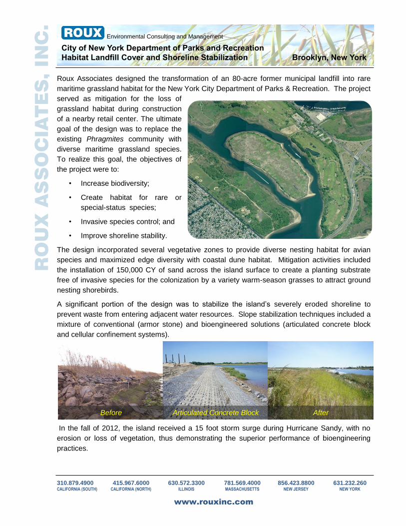
Roux Associates designed the transformation of an 80-acre former municipal landfill into rare
maritime grassland habitat for the New York City Department of Parks & Recreation. The project
served as mitigation for the loss of
grassland habitat during construction
of a nearby retail center. The ultimate
goal of the design was to replace the
existing Phragmites community with
diverse maritime grassland species.
To realize this goal, the objectives of
the project were to:
• Increase biodiversity;
• Create habitat for rare or
special-status species;
• Invasive species control; and
• Improve shoreline stability.
The design incorporated several vegetative zones to provide diverse nesting habitat for avian
species and maximized edge diversity with coastal dune habitat. Mitigation activities included
the installation of 150,000 CY of sand across the island surface to create a planting substrate
free of invasive species for the colonization by a variety warm-season grasses to attract ground
nesting shorebirds.
A significant portion of the design was to stabilize the island’s severely eroded shoreline to
prevent waste from entering adjacent water resources. Slope stabilization techniques included a
mixture of conventional (armor stone) and bioengineered solutions (articulated concrete block
and cellular confinement systems).
Before After Articulated Concrete Block
In the fall of 2012, the island received a 15 foot storm surge during Hurricane Sandy, with no
erosion or loss of vegetation, thus demonstrating the superior performance of bioengineering
practices.
310.879.4900 415.967.6000 630.572.3300 781.569.4000 856.423.8800 631.232.260 CALIFORNIA (SOUTH) CALIFORNIA (NORTH) ILLINOIS MASSACHUSETTS NEW JERSEY NEW YORK
www.rouxinc.com