enterprise manager cloud control 12c disaster recovery ... · cloud control high availability ......
TRANSCRIPT

An Oracle White Paper June 2013
Enterprise Manager Cloud Control 12c Disaster Recovery with Storage Replication
Enterprise Manager Cloud Control 12c Disaster Recovery with Storage Replication
Introduction ......................................................................................... 1 Cloud Control Architecture Overview .................................................. 2 Cloud Control High Availability ............................................................ 3 Cloud Control Disaster Recovery ........................................................ 5 Building a Cloud Control HA/DR Deployment ..................................... 6
Example Cloud Control Infrastructure ............................................. 6 Preparing for Cloud Control Installation .......................................... 7 Step 1 - Install first OMS ............................................................... 16 Step 2 - Configure SLBs on Primary and Standby Sites ............... 23 Step 3 - Add Repository Targets ................................................... 30 Step 4 - Add Second OMS ............................................................ 31 Step 5 - Add Standby Database .................................................... 37 Step 6 - Convert Standby Database to RAC ................................. 44 Step 7 - Push Agents to Physical OMS Hosts on Standby Site .... 47 Step 8 - Move HTTP Lock Files .................................................... 48 Summary of Setup ........................................................................ 49
Switchover and Failover .................................................................... 50 Switchover Procedure ................................................................... 50 Failover Procedure ........................................................................ 54
Keeping the Standby Site in Sync with the Primary .......................... 58 Conclusion ........................................................................................ 58

Enterprise Manager Cloud Control 12c Disaster Recovery with Storage Replication
1
Introduction
Oracle Enterprise Manager is Oracle’s integrated enterprise IT management product line and provides the industry’s first complete cloud lifecycle management solution. Oracle Enterprise Manager’s Business-Driven IT Management capabilities allow you to quickly set up, manage and support enterprise clouds and traditional Oracle IT environments from applications to disk. Enterprise Manager allows customers to achieve:
• Best service levels for traditional and cloud applications through management from a business perspective including Oracle Fusion Applications
• Maximum return on IT management investment through the best solutions for intelligent management of the Oracle stack and engineered systems
• Unmatched customer support experience through real-time integration of Oracle’s knowledgebase with each customer environment
With Enterprise Manager Cloud Control, Oracle offers a unique approach to systems management, enabling organizations to deploy a single tool with a tightly integrated set of features to manage all tiers in the datacenter as well as the entire lifecycle of applications. Through the use of Cloud Control, organizations are able to lower the cost of managing applications while at the same time dramatically improving quality of service.
The scope of operations possible with Cloud Control makes it far more critical in the data center than the other management tools. Without access to Cloud Control, administrators are left unaware of the health of their business critical applications and are also unable to undertake many of their day-to-day tasks. As such, High Availability has become a key requirement for many Cloud Control deployments. This white paper details how to install Cloud Control in a highly available and disaster tolerant configuration so that downtime can be minimized during events that would otherwise affect availability.

Enterprise Manager Cloud Control 12c Disaster Recovery with Storage Replication
2
Cloud Control Architecture Overview
Cloud Control provides a central point for monitoring and administration in the data center. To achieve this, it collects information from a variety of distributed components and consolidates it in a centralized repository. The key Cloud Control components must all work in concert for the Cloud Control system to operate correctly. The components involved in collecting, processing and presenting this information to users are as follows:
• Targets - A target, or more specifically, a target instance, can be defined as any entity that can be monitored within an enterprise. This entity can be an application running on a server, the server itself, the network, or any of its constituent parts.
• Oracle Management Agent (Agent) – The Oracle Management Agent is a software component that is installed on every monitored host in the enterprise. Agents collect information from the targets running on the host and send this information to the Oracle Management Service (OMS). Agents also perform operations against the targets on behalf of Cloud Control users. There are many different types of target that Cloud Control can manage. Examples include Host, VM Guest, Database, Listener, ASM, WebLogic Server, Service Bus and Fusion Applications components
• Oracle Management Service (OMS) – The Oracle Management Service is the central component in Cloud Control with which all other components interact (see Figure 1). The OMS is deployed on WebLogic Server and must be available in order for the agents to upload data and for administrators to access the Cloud Control console.
• Oracle Management Repository (Repository) – The Oracle Management Repository is used as a persistent data store. Examples of the information stored in the repository include user information, job definitions, monitoring and alerting settings and all configuration and monitoring data related to targets. The OMS cannot run if the repository is unavailable.
• Software Library – The Software Library is a filesystem repository that stores software entities such as software patches, virtual appliance images, reference gold images, application software, and their associated directive scripts. The Software Library is accessed by the OMS and is used extensively by the Cloud Control framework for features such as self-update and agent deployment.
• Console – The Console is a browser-based web application that is the main user interface for Cloud Control. This console allows the administrator to monitor, manage and report on the Cloud Control targets that have been set up.
• Enterprise Manager Command Line Interface (EM CLI) – EM CLI allows users to access Cloud Control functionality either interactively from a command line, or as part of a script. This allows Cloud Control operations to be integrated with complex business processes without user interaction.

Enterprise Manager Cloud Control 12c Disaster Recovery with Storage Replication
3
The interactions between the components described above are shown in the following diagram:
Figure 1: Key Components in a Cloud Control Deployment
Cloud Control Latency and Bandwidth Considerations
The latency between the components is a critical consideration when designing a Cloud Control deployment. As indicated in Figure 1, sub 1ms latency is required between the OMS and Repository tiers.
Conversely, the Cloud Control agents, console and EM CLI have been designed to tolerate communication over wide area networks where bandwidth is typically lower and latency higher.
The requirement for minimal latency between the OMS and repository components means that a Cloud Control deployment should have active OMS and Repository components located in close proximity to each other (typically in the same data center), while agents and users can be distributed across greater distances.
Cloud Control High Availability
High Availability typically protects a system from the failure of a single component. This is usually achieved by deploying redundant components that can quickly assume the work of a failed component. The topology depicted in Figure 1 shows that there is no redundancy of the OMS or Repository components. If the Repository or OMS servers were to fail the Cloud Control users and agents would not be able to connect to the application. Similarly, if the Software Library were unavailable software provisioning operations including agent deployment would be affected.
The following strategies can be used to protect the Cloud Control infrastructure from component failure:

Enterprise Manager Cloud Control 12c Disaster Recovery with Storage Replication
4
• The Software Library can be placed on highly available storage that is visible to all OMSs. An example of such highly available storage is Oracle’s Sun ZFS Storage Appliance which provides advanced features such as triple mirroring and clustering
• The Management Service tier can be made highly available by installing multiple OMSs behind a Server Load Balancer (SLB). The SLB monitors the status of each OMS and directs agent and user requests to available OMSs. The agents and users communicate with the OMS tier via the load balancer and do not need to know the physical addresses of the OMSs.
• The Repository can be made highly available with the use of Oracle Real Application Clusters (RAC), providing access to the repository database through multiple database servers.
Figure 2: Cloud Control in High Availability Configuration
The diagram above shows the topology of a Cloud Control deployment that is protected from component failure. This architecture allows Cloud Control to continue running upon failure of a database server, OMS server or storage server. In this configuration all running components are active.

Enterprise Manager Cloud Control 12c Disaster Recovery with Storage Replication
5
Cloud Control Disaster Recovery
While protection from component failure allows Cloud Control to continue processing if a single component such as an OMS or repository host should fail, it does not provide protection from events that affect the availability of the entire site. For these situations a Disaster Recovery (DR) solution is required.
The Disaster Recovery solution for a Cloud Control deployment involves replicating the OMS, Software Library and Repository components to a standby site. Because of the latency requirements mentioned earlier, only one site should be active at any given time, with the application traffic being directed to the appropriate site by a DNS entry that is updated when the standby site is activated. This solution can be combined with the high availability solution described earlier to ensure that failures ranging from component failure to a complete site outage can be recovered from with minimal disruption to the availability of Cloud Control.
The overall solution topology is shown in Figure 3 below:
The following are the key points regarding this solution:
• Duplicate hardware (OMS servers, Repository Servers, Storage Array, Load Balancer) is required at the standby site
• The primary OMS hostnames should be resolvable to the IP addresses of the corresponding standby hosts at the standby site. This can be achieved using one of the following methods:
• By installing OMSs at the primary site using the primary sites physical hostnames and configuring aliases for these hostnames on the corresponding hosts at the standby site.
Figure 3: Cloud Control Disaster Recovery Solution

Enterprise Manager Cloud Control 12c Disaster Recovery with Storage Replication
6
• By installing each OMS using an alias hostname that can be configured at both the primary and the standby sites
• The OMS installations and the Software Library should be located on filesystems that can be replicated between the primary and standby sites using storage replication (such as Oracle’s Sun ZFS Storage Appliance Remote Replication). The storage replication used should have snapshotting features so that consistent filesystem images can be taken and changes can be rolled back to a previous version if necessary.
• Oracle Data Guard should be used to transfer database changes between primary and standby sites
• Client access to Cloud Control is through a virtual hostname. This is a DNS entry that is configured to direct Cloud Control users and Agents to the currently active site
The failover to the standby site from the primary site consists of the following high-level operations:
• Stop OMSs at the primary site
• Failover/switchover of the database to the standby site
• Activate OMS and Software Library replicated storage at standby site
• Reverse storage replication direction
• Start OMSs at standby site
• Update DNS to send users and agents to standby site
This solution enables Cloud Control to be started on the standby site with minimal downtime and data loss even if the primary site has a complete outage.
Building a Cloud Control HA/DR Deployment
The remainder of this document outlines the steps that can be followed to implement a complete HA/DR solution for Cloud Control utilizing a pair of Oracle Sun ZFS Storage Appliances as our storage replication solution.
Example Cloud Control Infrastructure
To provide full capacity on the event of activating the standby site, the same hardware resources were deployed at both primary and standby sites. The hardware at each site comprised:
• 2 node RAC database cluster for Repository database
• 2 servers for OMSs
• Server Load Balancer
• ZFS storage appliance for OMS installations and Software Library*

Enterprise Manager Cloud Control 12c Disaster Recovery with Storage Replication
7
* Note that the storage appliance used should support replication between primary and standby sites. It should also support snapshots so that point-in-time consistent copies can be taken.
The high level steps for building the configuration are as follows:
Figure 4: Workflow for Building Cloud Control Disaster Recovery Solution
Preparing for Cloud Control Installation
The steps outlined assume that certain tasks have been completed prior to installation. The pre-requisites are outlined below.
Preparing Database Clusters
The Primary and Standby database clusters should be setup on the primary and standby sites respectively prior to the installation of Cloud Control.
In the example installation each cluster was a 2 node cluster running Oracle Enterprise Linux 5.6 (x86-64). Further configuration details for each cluster were as follows:
• Oracle Clusterware 11g Release 2 (11.2) binaries installed and configured
• Oracle Database 11g Release 2 (11.2) binaries installed and configured
• SCAN listeners configured
• Primary system names of emrep1 and emrep2 forming cluster emrep-cl
• Standby system names of emreps1 and emreps2 forming cluster emreps-cl

Enterprise Manager Cloud Control 12c Disaster Recovery with Storage Replication
8
• As per Oracle Best Practice, the Primary and Standby clusters were each configured with ASM disks for shared database storage.
• ‘DATA’ (Data) and ‘FRA’ (Fast Recovery Area) ASM Diskgroups were configured and available on the Primary and Standby clusters. As per Oracle Best Practice, these were configured with EXTERNAL redundancy as the underlying storage hardware supports redundancy.
Oracle database 11gR2 was used as it allows for the use of the Single Client Access Name (SCAN) for client connections. If possible, it is recommended to use a SCAN address as it allows for the addition and removal of database cluster nodes without reconfiguration of the OMS database connections.
For more information on Single Client Access Name refer to the Oracle Database 11g Release 2 Real Application Clusters Administration and Deployment Guide.
Preparing the Repository Database
During the installation of Cloud Control the installer will prompt the user to specify a database to be used as the Cloud Control repository. If you plan to use a RAC database as a repository, it is recommended to create your RAC database prior to the installation of Cloud Control. This approach (as opposed to installing using a single instance database and then converting to RAC) helps to reduce the overall steps and time taken to complete the configuration.
In the example configuration, we created a database to be used as the primary Cloud Control repository on the primary database cluster with the name ‘emrep’. This database consisted of the emrep1 and emrep2 instances.
Figure 5: RAC Database Topology
The datafiles, redologs and controlfiles were placed on the ‘DATA’ shared ASM diskgroup.
In addition to meeting the requirements specified in the Enterprise Manager Cloud Control Basic Installation Guide, we configured the database in ARCHIVELOG mode and enabled Flashback Database. It is recommended that these options be enabled when the database is created, as by doing so it is possible to avoid having to reconfigure the database when creating and managing the Standby Database later on.

Enterprise Manager Cloud Control 12c Disaster Recovery with Storage Replication
9
For further information and recommendations on the prerequisites for creating the repository database on RAC refer to the following documentation:
• Clusterware Administration and Deployment Guide
• Real Application Clusters Administration and Deployment Guide
• Automatic Storage Management Administrator’s Guide
• Enterprise Manager Cloud Control Basic Installation Guide
Preparing Shared Storage for OMSs and Software Library
The Disaster Recovery solution for the OMSs and Software Library requires the use of replicated storage between the primary and standby sites. In our configuration we used a pair of ZFS appliances.
Configuring Storage Pools
A Storage Pool is created over a set of physical disks and filesystems are then created over the Storage Pools. We decided to share a common Storage Pool for the Software Library and the OMS installations. The Storage Pool was created such that it was large enough to accommodate both OMS installs and all artifacts that may be placed in the Software Library over time.
We created Storage Pools the primary and standby ZFS appliances as follows:
ZFS STORAGE POOL CONFIGURATION
SITE POOL SIZE DATA PROFILE
Primary em12c_p 300GB Double Parity
Standby em12c_s 300GB Double Parity
Figure 6: ZFS Storage Pool Configuration

Enterprise Manager Cloud Control 12c Disaster Recovery with Storage Replication
10
Configuring Projects and Shares at the Primary Site
An example of the Share/Project setup for a ZFS storage appliance located at the primary site is shown below.
ZFS PROJECT/SHARE CONFIGURATION FOR PRIMARY SITE
PROJECT SHARE SIZE DESCRIPTION MOUNT DETAILS
OMS_Project OMS1 60GB Share used to store the installation of
Enterprise Manager for first OMS
Mounted as /em on
oms1p.example.com
OMS_Project OMS2 60GB Share used to store the installation of
Enterprise Manager for the second OMS
Mounted as /em on
oms2p.example.com
SWLIB_Project SWLIB 100GB Share used as Software Library. Shared by
OMS1 and OMS2
Mounted as /swlib on
oms1p.example.com and
oms2p.example.com
Figure 7: ZFS Share Configuration

Enterprise Manager Cloud Control 12c Disaster Recovery with Storage Replication
11
Configuring Replication Between Primary and Standby Sites
The OMSs and Software Library will be kept in sync on the standby site by using ZFS Remote Replication. We configured replication at the primary site by adding the standby site’s Storage Pool as a Remote Replication target.
Figure 8: Configuring ZFS Remote Replication Target at the Primary Site
We then set up replication actions on the OMS_Project and SWLIB_Project. For both Projects, we configured this for updates to be sent to the remote site continuously, meaning that as soon as the last set of incremental changes has been sent to the remote site the next set of changes is sent (note that this is not the same as sending the changes synchronously). If bandwidth between the sites in inadequate for continuous replication, sending the updates on a schedule can be used instead, and the schedule should be as frequent as the infrastructure will allow. If required the Projects can be configured with different replication actions (for example OMS_Project on an hourly schedule and SWLIB_Project in continuous mode).

Enterprise Manager Cloud Control 12c Disaster Recovery with Storage Replication
12
Figure 9: Configuring ZFS Pool Replication Action
The diagram below shows the topology of the ZFS appliances:
SWLIB Project OMS Project
OMS1 Share SWLIB Share OMS2 Share
SWLIB Project OMS Project
OMS1 Share SWLIB Share OMS2 Share
Continuous Replication
Continuous Replication
Primary Site (Source) Standby Site (Target)
Figure 10: ZFS Storage Topology

Enterprise Manager Cloud Control 12c Disaster Recovery with Storage Replication
13
Preparing OMS Nodes
When creating a highly available OMS tier, more than one management service must be configured. In the example configuration we used a pair of Linux hosts as primary OMS servers. These were configured as follows:
• Both servers running Oracle Enterprise Linux 5.6 (x86-64)
• System names were oms1-p.example.com and oms2-p.example.com and were configured using Fully Qualified Domain Names (FQDN) naming in /etc/hosts
• The SWLIB ZFS Share was mounted read/write on the /swlib mount point on oms1-p.example.com and oms2-p.example.com
• The OMS1 ZFS Share was mounted read/write on the /em mount point on oms1-p.example.com
• The OMS2 ZFS Share was mounted read/write on the /em mount point on oms2-p.example.com
A pair of identical Servers for OMS nodes was also deployed at the standby site. The hostnames of the standby OMS servers were oms1-s.example.com and oms2-s.example.com. The ZFS Shares were not mounted on these hosts at this time.
For further details of the requirements for the OMS see the Enterprise Manager Cloud Control Basic Installation Guide.
Network and DNS Planning
The Hostname and IP address configuration of the Physical OMS servers is shown in the following table:
OMS HOST IP ADDRESSES/HOSTNAMES
HOSTNAME IP ADDRESS DESCRIPTION
oms1-p.example.com 123.1.2.111 Physical host for OMS1 on Primary site
oms2-p.example.com 123.1.2.112 Physical host for OMS2 on Primary site
oms1-s.example.com 123.2.2.111 Physical host for OMS1 on Standby site
oms2-s.example.com 123.2.2.112 Physical host for OMS2 on Standby site
The DR solution requires that the hostnames used for the OMS installation resolve to the IP addresses of the primary nodes at the primary site and to the IP addresses of the standby nodes at the standby site. This can be achieved using one of the following methods:
Option 1:

Enterprise Manager Cloud Control 12c Disaster Recovery with Storage Replication
14
• Install each OMS at the primary site using the physical hostnames of the primary hosts.
• Standby hosts should have an alias configured for the hostname of the corresponding primary site host
Option 2:
• Install each OMS at the primary site using an alias Hostname (eg. oms1-v, oms2-v).
• At the primary site, the alias hostnames should resolve to the primary host’s physical IP addresses
• At the standby site, the alias hostnames should resolve to the standby host’s physical IP addresses
• The hostname resolution can be done using local hostname resolution (eg. /etc/hosts file) or by using separate DNS servers for the primary and standby sites.
In the example configuration we decided to use Option 1 with local hostname resolution (/etc/hosts).
The /etc/hosts for the OMS hosts at the Primary Site included the following entries:
A ping of oms1-p.example.com from the OMS hosts at the primary site results in a reply from the primary site:
The /etc/hosts configuration at the standby site was as follows:
A ping of oms1-p.example.com from the OMS hosts at the standby site results in a reply from the standby site:
127.0.0.1 localhost.localdomain 123.1.2.111 oms1-p.example.com oms1-p #OMS1 123.1.2.112 oms2-p.example.com oms2-p #OMS2
[oracle@oms1-p ~]$ ping oms1-p.example.com PING oms1-p.example.com (123.1.2.111) 56(84) bytes of data. 64 bytes from oms1-p.example.com (123.1.2.111): icmp_seq=1 ttl=64 time=0.018 ms 64 bytes from oms1-p.example.com (123.1.2.111): icmp_seq=2 ttl=64 time=0.020 ms 64 bytes from oms1-p.example.com (123.1.2.111): icmp_seq=3 ttl=64 time=0.022 ms
127.0.0.1 localhost.localdomain 123.2.2.111 oms1-s.example.com oms1-s oms1-p.example.com #OMS1 123.2.2.112 oms2-s.example.com oms2-s oms2-p.example.com #OMS2
[oracle@oms1-s ~]$ ping oms1-p.example.com PING oms1-s.example.com (123.2.2.111) 56(84) bytes of data. 64 bytes from oms1-s.example.com (123.2.2.111): icmp_seq=1 ttl=64 time=0.018 ms 64 bytes from oms1-s.example.com (123.2.2.111): icmp_seq=2 ttl=64 time=0.020 ms 64 bytes from oms1-s.example.com (123.2.2.111): icmp_seq=3 ttl=64 time=0.022 ms

Enterprise Manager Cloud Control 12c Disaster Recovery with Storage Replication
15
Application Virtual Hostname Planning
Finally, a hostname through which the Cloud Control clients (agents and users) should access Cloud Control is required. When the primary site is active, this hostname should be configured in DNS to resolve to the IP address hosted by the primary site SLB. When the standby site is activated, the DNS entry should be updated so that the hostname resolves to the IP address hosted by the standby site SLB.
Figure 11: Cloud Control DNS/Load Balancer Topology
The DNS configuration for the Cloud Control application hostname is shown in the table below:
DNS RECORDS FOR CLIENT ACCESS AND LOAD BALANCERS
DNS NAME DNS RECORD
TYPE
VALUE COMMENTS
em.example.com CNAME slb_primary.example.com Virtual Hostname used by Cloud Control clients to
communicate with Management Service. Should
point to SLB of currently active site
slb_primary.example.com A 123.1.2.110 Primary Site SLB address
slb_standby.example.com A 123.2.2.110 Standby Site SLB address

Enterprise Manager Cloud Control 12c Disaster Recovery with Storage Replication
16
As part of a switchover or failover to the standby, the DNS entry for em.example.com should be updated to point to the slb_standby.example.com record. This step can optionally be automated with the use of a Global Traffic Manager (GTM).
To ensure that DNS records cached by the Cloud Control clients are updated in a timely fashion after an update, it is recommended to set the TTL for the em.example.com CNAME to a low value such as 60 seconds. This will ensure that DNS changes will quickly propagate to all clients.
After all of the preparation steps have been completed, the installation and configuration of the Disaster Recovery solution can be started.
Step 1 - Install first OMS
We started the installer from the first OMS host on the primary site (oms1-p.example.com).
As Cloud Control will also need to be started up on the hosts located on the standby site, it is necessary to ensure that the oracle Inventory associated with the installation will also be available on the standby site. This is required for performing patching operations and upgrades when the standby site is active.
As this was the first Oracle installation on oms1-p.example.com we were prompted to specify a location for the Oracle Inventory. We set the location to a directory on the /em filesystem which will be made available through storage replication at the standby site.

Enterprise Manager Cloud Control 12c Disaster Recovery with Storage Replication
17
On Step 5 of the installer we chose to do an Advanced Installation
When prompted by the installer to specify the Middleware Home and Agent Base directories we also specified the /em filesystem (located on our storage appliance). As in our case we have chosen to install using the primary site’s physical hostnames we left the Host Name field as the default.

Enterprise Manager Cloud Control 12c Disaster Recovery with Storage Replication
18
In Step 8 we entered the passwords for the WebLogic Domain and Node Manager. We left the OMS instance base as the default which is located on the /em replicated filesystem.
In Step 9 we provided the login credentials for the repository database.

Enterprise Manager Cloud Control 12c Disaster Recovery with Storage Replication
19
Tip: Entering a cluster database instance for the Repository will prompt for modification of the database connection string. If using Oracle Database 11gR2, it is recommended to specify a connect string that uses the SCAN address. Use of the SCAN address makes it possible for nodes to be added and removed from the RAC cluster without requiring changes to OMS connect strings.
An example of a connect string using a SCAN address is as follows:
(DESCRIPTION = (ADDRESS =
(PROTOCOL = TCP) (HOST = emrep-cl-scan.example.com)(PORT = 1521)
) (CONNECT_DATA =
(SERVER = DEDICATED) (SERVICE_NAME = emrep)
) )
For the repository configuration details in Step 10, we specified the previously created DATA ASM Diskgroup as the location for the Management Tablespace, Configuration Data Tablespace and JVM Diagnostics Data Tablespace.
For the Software Library location we specified /swlib, which is also a filesystem located on the ZFS replicated storage.

Enterprise Manager Cloud Control 12c Disaster Recovery with Storage Replication
20
In Step 11 we specified the ports to be used in the installation:
Of these ports, the following are relevant for the SLB configuration later on:

Enterprise Manager Cloud Control 12c Disaster Recovery with Storage Replication
21
• Enterprise Manager Upload HTTP Port: 4889
• Enterprise Manager Upload HTTP SSL Port: 4900
• Enterprise Manager Central Console HTTP Port: 7788
• Enterprise Manager Central Console HTTP SSL Port: 7799
Following successful installation, a summary screen describing how to access Cloud Control is presented. The information shown on this screen should be noted.
Immediately after the installation the initial OMS configuration should be verified.
As shown above, the OMS has been installed using the physical hostname of oms1-p.example.com
The output above also shows that Agent Upload and OMS Console are Locked. This is the default configuration and it means that Browser-OMS and Agent-OMS traffic must be in HTTPS and HTTP will not be allowed.
We checked the repository connect by issuing the command “emctl config oms –list_repos_details”
$ cd /em/Middleware/oms/bin
$ ./emctl status oms -details Oracle Enterprise Manager Cloud Control 12c Release 3 Copyright (c) 1996, 2013 Oracle Corporation. All rights reserved. Enter Enterprise Manager Root (SYSMAN) Password : Console Server Host : oms1-p.example.com HTTP Console Port : 7788 HTTPS Console Port : 7799 HTTP Upload Port : 4889 HTTPS Upload Port : 4900 EM Instance Home : /em/Middleware/gc_inst/em/EMGC_OMS1 OMS Log Directory Location : /em/Middleware/gc_inst/em/EMGC_OMS1/sysman/log OMS is not configured with SLB or virtual hostname Agent Upload is locked. OMS Console is locked. Active CA ID: 1 Console URL: https://oms1-p.example.com:7799/em Upload URL: https://oms1-p.example.com:4900/empbs/upload WLS Domain Information Domain Name : GCDomain Admin Server Host : oms1-p.example.com Admin Server HTTPS Port: 7101 Admin Server is RUNNING Managed Server Information Managed Server Instance Name: EMGC_OMS1 Managed Server Instance Host: oms1-p.example.com WebTier is Up Oracle Management Server is Up Oracle Management Server is Up

Enterprise Manager Cloud Control 12c Disaster Recovery with Storage Replication
22
This shows that the OMS is using the SCAN address to connect to the repository database and therefore the OMS connect string will not need to be reconfigured if nodes are added to or removed from the RAC database.
We can also check the status of the agent by using the ‘emctl status agent’ command from the agent home
The Agent URL shows that this agent is also running on the physical hostname oms1-p.example.com. The Repository URL shows that the agent is communicating with the OMS using the physical hostname.
$ ./emctl status agent Oracle Enterprise Manager Cloud Control 12c Release 3 Copyright (c) 1996, 2013 Oracle Corporation. All rights reserved. --------------------------------------------------------------- Agent Version : 12.1.0.3.0 OMS Version : 12.1.0.3.0 Protocol Version : 12.1.0.1.0 Agent Home : /em/Agent/agent_inst Agent Binaries : /em/Agent/core/12.1.0.3.0 Agent Process ID : 13910 Parent Process ID : 13860 Agent URL : https://oms1-p.example.com:3872/emd/main/ Repository URL : https://oms1-p.example.com:4900/empbs/upload Started at : 2013-02-19 03:40:05 Started by user : oracle Last Reload : (none) Last successful upload : 2013-02-28 06:03:24 Last attempted upload : 2013-02-28 06:03:24 Total Megabytes of XML files uploaded so far : 62.05 Number of XML files pending upload : 0 Size of XML files pending upload(MB) : 0 Available disk space on upload filesystem : 47.91% Collection Status : Collections enabled Heartbeat Status : Ok Last attempted heartbeat to OMS : 2013-02-28 06:07:31 Last successful heartbeat to OMS : 2013-02-28 06:07:31 Next scheduled heartbeat to OMS : 2013-02-28 06:08:31 -------------------------------------------------------------- Agent is Running and Ready
$ ./emctl config oms -list_repos_details Oracle Enterprise Manager Cloud Control 12c Release 3 Copyright (c) 1996, 2013 Oracle Corporation. All rights reserved. Repository Connect Descriptor : (DESCRIPTION=(ADDRESS_LIST=(ADDRESS=(PROTOCOL=TCP)(HOST=emrep-clscan. example.com)(PORT=1521)))(CONNECT_DATA=(SERVICE_NAME=emrep))) Repository User : SYSMAN

Enterprise Manager Cloud Control 12c Disaster Recovery with Storage Replication
23
After Step 1, the Cloud Control topology is as follows:
Step 2 - Configure SLBs on Primary and Standby Sites
As shown above, the install of the first OMS configures the system so that the Cloud Control users and agents connect directly to the first OMS using its physical hostname. In a highly available Cloud Control configuration, multiple OMS servers are present and users and agent should connect to the OMSs via a server load balancer (SLB) which is able to direct traffic to available management services.
SLB configuration should be done immediately after installing the first OMS.
The SLB used in our example configuration was an F5 BIG-IP Local Traffic Manager running 11.1.0, Build 2268.0 Hotfix HF5. As our OMS is configured only for secure console and upload traffic, we only needed to configure the Secure Upload and Secure Console services on the SLB.
Setting up the SLB consisted of configuring:
• Health Monitors
• TCP Profiles
• Pools
• Persistence Profile (Console service only)
• Virtual Servers
The table below summarizes the F5 objects that were created on the SLB:
SUMMARY OF SLB SETUP
Figure 12: Cloud Control Topology After First OMS Install

Enterprise Manager Cloud Control 12c Disaster Recovery with Storage Replication
24
SITE
CLOUD
CONTROL
SERVICE
TCP
PORT MONITOR NAME PERSISTENCE POOL NAME
LOAD
BALANCING
VIRTUAL
SERVER
NAME
VIRTUAL
SERVER
PORT
Primary,
Standby
Secure
Upload
4900 mon_ccsu4900 None pool_ccsu4901 Round
Robin
vs_ccsu4900 4900
Primary,
Standby
Secure
Console
7799 mon_ccsc7799 Source IP pool_ccsc7799 Round
Robin
vs_ccsc443 443
Step 2.1: Create Health Monitors
Health Monitors check the status of a service on an ongoing basis, at a set interval. If the service being checked does not respond within a specified timeout period, or the status of the service indicates that the performance has degraded, the system automatically takes it out of the pool and will choose other members of the pool.
The Health Monitors were configured using the settings in the table below:
SLB HEALTH MONITOR SETUP
SITE
CLOUD
CONTROL
SERVICE
TCP
PORT MONITOR NAME TYPE INTERVAL TIMEOUT SEND STRING
RECEIVE
STRING
Primary,
Standby
Secure
Console
7799 mon_ccsc7799 https 5 16 GET
/em/console/Status.jsp\r\n
Enterprise
Manager
Console is
UP
Primary,
Standby
Secure
Upload
4900 mon_ccsu4900 https 60 181 GET /empbs/upload \r\n Http
Receiver
Servlet
active!
Step 2.2 Create TCP Profiles
TCP Profiles were created at each site to control the behavior of Cloud Control traffic.
We created two TCP Profiles, one for the Secure Console service and one for the Secure Upload service.
These were created with the default settings for a TCP Profile.

Enterprise Manager Cloud Control 12c Disaster Recovery with Storage Replication
25
Step 2.3 Create Pools
A pool is a set of servers grouped together to receive traffic on a specific TCP port using a load balancing method. Each pool can have its own unique characteristic for a persistence definition and the load-balancing algorithm used. The preferred setting of the load balance algorithm for all Cloud Control pools is Least Connections (Member).
We created pools on the load balancer as follows:
SLB POOLS SETUP
SITE
CLOUD
CONTROL
SERVICE
POOL NAME
ASSOCIATED
HEALTH
MONITOR
LOAD BALANCING MEMBERS
Primary Secure
Console
pool_ccsc7799 mon_ccsc7799 Least
Connections
(member)
oms1-p.example.com:7799
oms2-p.example.com:7799
Primary Secure
Upload
pool_ccsu4900 mon_ccsu4900 Least
Connections
(member)
oms1-p.example.com:4900
oms2-p.example.com:4900
Standby Secure
Console
pool_ccsc7799 mon_ccsc7799 Least
Connections
(member)
oms1-s.example.com:7799
oms2-s.example.com:7799
Standby Secure
Upload
pool_ccsu4900 mon_ccsu4900 Least
Connections
(member)
oms1-s.example.com:4900
oms2-s.example.com:4900

Enterprise Manager Cloud Control 12c Disaster Recovery with Storage Replication
26
Even though the second OMS has not been configured yet, it is recommended to add the second OMS host to the server pools at this time as it means modifying the SLB configuration subsequent to the installation of the second OMS can be avoided.
Step 2.4 Create Console Persistence Profile
A console persistence profile is required to ensure that all Cloud Control user requests for a given session are directed to the same management service for the entire session. Without a Persistence Profile such as this, user sessions could span multiple OMSs, and require the Cloud Control user to login multiple times.
We created a Persistence Profile at each site with the following attributes:
SLB PERSISTENCE PROFILE SETUP
SITE
CLOUD
CONTROL
SERVICE
F5 PERSISTENCE
PROFILE NAME TYPE TIMEOUT EXPIRATION
Primary, Standby Secure
Console
sourceip_ccsc7799 Source
Address
Affinity
3600 Not Applicable
Figure 5: Creating Persistence Profile for Secure Console
Step 2.5 Create Virtual Servers

Enterprise Manager Cloud Control 12c Disaster Recovery with Storage Replication
27
The final load balancer configuration step was to define our virtual servers. A virtual server, with its virtual IP Address and port number, is the client addressable hostname or IP address through which members of a load balancing pool are made available to a client. After a virtual server receives a request, it directs the request to a member of the pool based on a chosen load balancing method.
We created virtual servers for the Secure Console and Secure Upload services using the settings in the following table:
SLB VIRTUAL SERVER SETUP
SITE
CLOUD
CONTROL
SERVICE
VIRTUAL
SERVER NAME
VIRTUAL IP AND
PORT
PROTOCOL
PROFILE
(CLIENT)
HTTP
PROFILE
SNAT
POOL IRULE
DEFAULT
POOL
DEFAULT
PERSISTENCE
PROFILE
Primary Secure
Console
vs_ccsc443 123.1.2.110:443 tcp_ccsc7799 None Auto None pool_ccsc
7799
sourceip_
ccsc7799
Primary Secure
Upload
vs_ccsu4900 123.1.2.110:4900 tcp_ccsu4900 None Auto None pool_ccsu
4900
None
Standby Secure
Console
vs_ccsc443 123.2.2.110:443 tcp_ccsc7799 None Auto None pool_ccsc
7799
sourceip_
ccsc7799
Standby Secure
Upload
vs_ccsu4900 123.2.2.110:4900 tcp_ccsu4900 None Auto None pool_ccsu
4900
None
Step 2.6: Update OMS configuration
After the SLB configuration was completed we needed to resecure the OMS using the em.example.com hostname. This hostname has been registered in DNS as a canonical name that points to slb_prim.example.com. This is the hostname that the Cloud Control users and agents will use to communicate with the OMS.
Following this command the OMS was restarted.
emctl secure oms -sysman_pwd <sysman_pwd> -reg_pwd <agent_reg_password> -host em.example.com -secure_port 4900 -slb_port 4900 -slb_console_port 443 -console -lock_upload -lock_console

Enterprise Manager Cloud Control 12c Disaster Recovery with Storage Replication
28
“emctl status –details” output now shows that the OMS is configured with the em.example.com hostname. The em.example.com hostname in turn points to an IP address hosted by the primary SLB.
The above output shows that the Console and Upload URLs now reference the em.example.com hostname rather than the physical host of the OMS.
The agent that was previously deployed on the OMS is still configured to upload to the oms1.example.com virtual hostname of the first OMS server. This can be seen from the output of an “emctl status agent” command:
$ ./emctl status oms -details Oracle Enterprise Manager Cloud Control 12c Release 12.1.0.3.0 Copyright (c) 1996, 2013 Oracle Corporation. All rights reserved. Enter Enterprise Manager Root (SYSMAN) Password : Console Server Host : oms1-p.example.com HTTP Console Port : 7788 HTTPS Console Port : 7799 HTTP Upload Port : 4889 HTTPS Upload Port : 4900 SLB or virtual hostname: em.example.com HTTPS SLB Upload Port : 4900 HTTPS SLB Console Port : 443 Agent Upload is locked. OMS Console is locked. Active CA ID: 1 Console URL: https://em.example.com:443/em Upload URL: https://em.example.com:4900/empbs/upload
WLS Domain Information
Domain Name : GCDomain
Admin Server Host: oms1.example.com
Managed Server Information
Managed Server Instance Name: EMGC_OMS1
Managed Server Instance Host: oms1.example.com

Enterprise Manager Cloud Control 12c Disaster Recovery with Storage Replication
29
In order for this agent to start uploading via the em.example.com hostname we performed a resecure on the agent:
emctl secure agent –emdWalletSrcUrl https://em.example.com:4901/em
Following the resecure of the agent, the Repository URL in the “emctl status agent” output will reflect the em.example.com hostname instead of the physical hostname of the first OMS server.
All Cloud Control clients should now connect using the em.example.com hostname.
https://em.example.com/em
EM CLI should also be reconfigured to connect using em.example.com at this point. This is done with the following command:
emcli setup -url=https://em.example.com/em -username=em_user
For more information regarding configuring EM CLI refer to the Command Line Interface Guide.
$ ./emctl status agent Oracle Enterprise Manager 12c Release 3 Copyright (c) 1996, 2013 Oracle Corporation. All rights reserved. --------------------------------------------------------------- Agent Version : 12.1.0.3.0 OMS Version : 12.1.0.3.0 Protocol Version : 12.1.0.1.0 Agent Home : /u01/Middleware/agent/agent_inst Agent Binaries : /u01/Middleware/agent/core/12.1.0.3.0 Agent Process ID : 15661 Parent Process ID : 15594 Agent URL : https://oms1-p.example.com:3872/emd/main/ Repository URL : https://oms1-p.example.com:4901/empbs/upload Started at : 2012-02-09 06:48:14 Started by user : oracle Last Reload : (none) Last successful upload : 2012-02-21 19:58:44 Last attempted upload : 2012-02-21 20:02:04 Total Megabytes of XML files uploaded so far : 182.23 Number of XML files pending upload : 1,488 Size of XML files pending upload(MB) : 24.28 Available disk space on upload filesystem : 57.28% Collection Status : Collections enabled Last attempted heartbeat to OMS : 2012-02-23 05:25:48 Last successful heartbeat to OMS : 2012-02-21 20:00:49 --------------------------------------------------------------- Agent is Running and Ready

Enterprise Manager Cloud Control 12c Disaster Recovery with Storage Replication
30
The Cloud Control topology after the SLB configuration has been completed is as shown below:
As shown in the diagram, the agents and clients now communicate with the OMS via the em.example.com DNS name and this directs their requests to the Primary site SLB. For further details regarding configuration of Cloud Control with F5 Load Balancers, refer to the Oracle/F5 white paper Configuring OMS High Availability with F5 Big-IP Local Traffic Manager.
Step 3 - Add Repository Targets
Following the installation of Cloud Control, the hosts that are used for the Repository database are not visible as Cloud Control targets. In order to add them to the Cloud Control environment they should each have an agent installed. The agents can be installed by navigating to Setup | Add Target| Add Targets Manually and adding the Hosts using the Add Host Targets wizard
Figure 13: Cloud Control Topology after SLB Configuration

Enterprise Manager Cloud Control 12c Disaster Recovery with Storage Replication
31
After the repository hosts are added, the repository itself can be added as a database target by navigating to Targets | Databases and using the add target wizard. The cluster target for the primary database cluster can also be added as part of this flow.
Step 4 - Add Second OMS
Step 4.1 Set Inventory Location
As was the case with the first OMS, it is necessary to ensure that the oracle Inventory associated with the installation of the second OMS will also be available on the standby site. To achieve this we set the location of the Oracle Inventory to a location on the /em filesystem which will be made available through storage replication at the standby site. This was done by creating the /etc/oraInst.loc file with the following entries:
inventory_loc=/em/oraInventory inst_group=dba
Step 4.2 Push agent to host of second OMS
Adding OMSs to Cloud Control is done by submitting the 'Add Management Service' Deployment Procedure from the Cloud Control console. Before the Deployment Procedure can be executed on the second OMS host, a management agent must be pushed to the host. The management agent was pushed using the Add Targets Wizard and specifying the physical hostname (oms2-p.example.com) in the Host field.
In Step 2 of the wizard we specified the same port for the agent as was used for the agent on the first OMS (3872 in our case)

Enterprise Manager Cloud Control 12c Disaster Recovery with Storage Replication
32
Step 4.3 Run Add Management Service Deployment Procedure
After the agent had been deployed on oms2-p.example.com the 'Add Management Service' Deployment Procedure was submitted.
The “Add Management Service” Deployment Procedure is provided out of the box. It runs a series of pre-requisite checks on the target Management Service host and performs a clone of the primary Management Service to add a second OMS.
Prior to running the Deployment Procedure, Self Update should be checked in case there are any new versions of the procedure available. This is done navigating to Self Update (Setup | Extensibility | Self Update) and checking the Provisioning Bundle Updates.
After ensuring that the latest version of the Deployment Procedure was downloaded and applied, we navigated to Enterprise | Provisioning and Patching | Procedure Library and selecting the Add Management Service Deployment Procedure.

Enterprise Manager Cloud Control 12c Disaster Recovery with Storage Replication
33
The Deployment Procedure is submitted by clicking on the Launch button. This provides a guided workflow for adding the new Management Service. The Deployment Procedure asks for confirmation that prerequisites such as configuration of the Software Library and load balancer have completed.
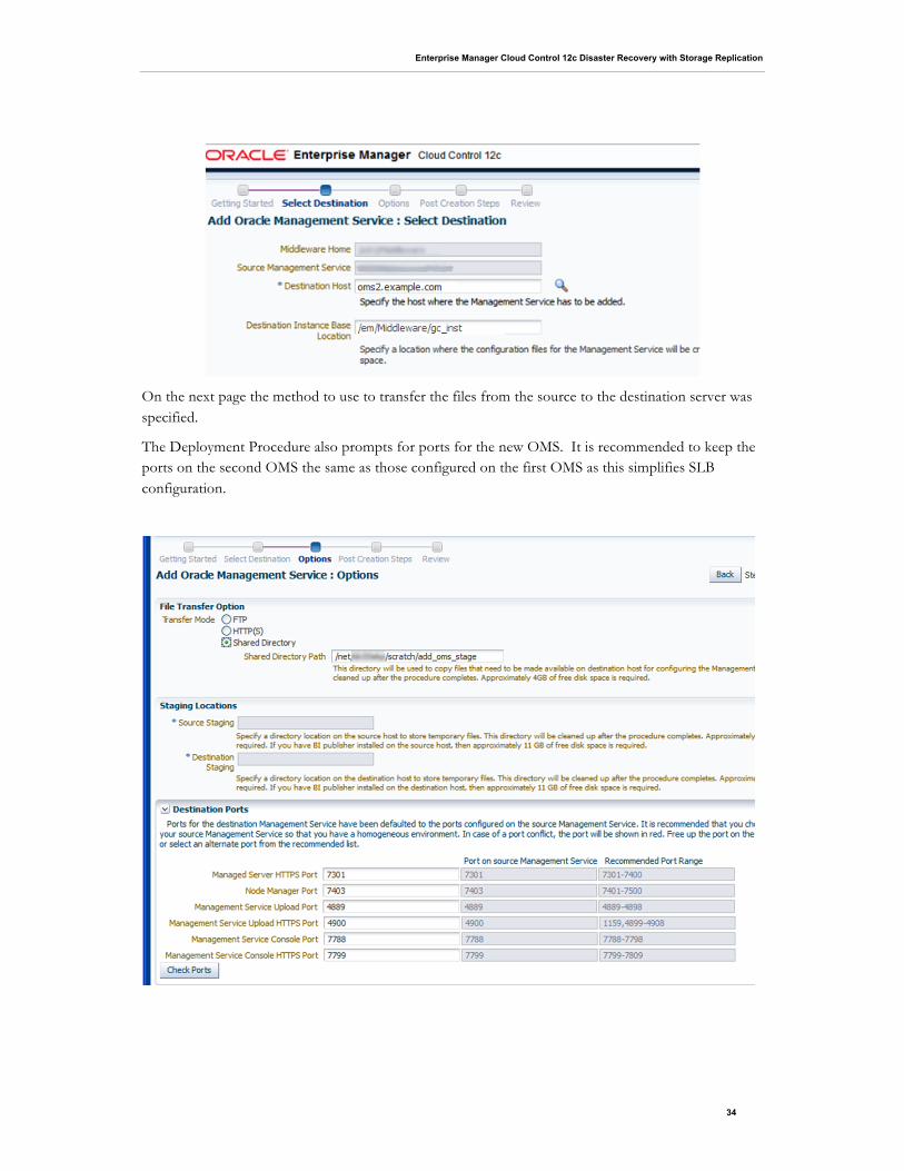
The next step of the installer wizard prompts for the destination host and install location for the second OMS. The ‘Destination Instance Base Location’ should be set to the same value as on the source OMS. At this step it is also necessary to provide login credentials for both the source server (first OMS host) and the target server (new OMS host). Named Credentials can be used for this step.
Enterprise Manager Cloud Control 12c Disaster Recovery with Storage Replication
34
On the next page the method to use to transfer the files from the source to the destination server was specified.
The Deployment Procedure also prompts for ports for the new OMS. It is recommended to keep the ports on the second OMS the same as those configured on the first OMS as this simplifies SLB configuration.

Enterprise Manager Cloud Control 12c Disaster Recovery with Storage Replication
35
Finally, the Deployment Procedure displays some instructions for steps that need to be completed on the SLB after the second OMS is added. These steps need to be followed if the second OMS details are not already present in the SLB configuration.
It is possible to optionally specify an email address where the steps can be sent (note: Email Notification Method must have been configured from the Setup | Notifications | Notification Methods page for this).
When submitted, the procedure executes the process of adding the second OMS by cloning the software homes from the source server to the target server.
After the Add Management Service Deployment procedure completes the EMGC_GCDomain WebLogic Domain should be refreshed. This is done by navigating to the Farm or Domain home and selecting Refresh WebLogic Domain from the Target menu.

Enterprise Manager Cloud Control 12c Disaster Recovery with Storage Replication
36
The diagram below shows the Cloud Control topology following installation of the second OMS:
As illustrated, the load balancer is now able to direct traffic to either OMS. In the event that we should lose one of the OMSs, the load balancer will stop directing traffic to it and application availability will
Figure 14: Cloud Control Topology After Second OMS is Added

Enterprise Manager Cloud Control 12c Disaster Recovery with Storage Replication
37
be maintained. We are now protected from the loss of a database node in the Repository tier and a Management Service in the OMS tier.
Step 5 - Add Standby Database
With the Cloud Control management repository running on Real Application Clusters and the addition of a second management service, the Cloud Control installation is protected from component failure at the primary site. In the event a database or OMS server is unavailable, the application can still continue to function.
Adding a Standby Database ensures that the repository database is protected from complete failure. Standby Databases provide a copy of the data in a separate environment, which can be activated in the event of a primary failure.
Note: A further standby database can optionally be considered at the primary site. This protects the repository database from failure without requiring a full DR failover. This configuration is not covered in this document.
Install agents on Standby Database nodes
Before the standby database can be configured, the standby database servers must be added to the Cloud Control environment. This was done using the agent deployment wizard as seen in previous steps
Goto Setup | Add Target | Add Host Targets and use the guided workflow for Add Host Targets to complete the installation of the Cloud Control agent.
Add standby cluster targets
After the agent has been deployed to the standby node, the cluster target for the standby nodes was added.
This was done by navigating to Setup | Add Targets | Add Targets Manually. Then select “Add Non-Host Targets Using Guided Process” and selecting “Oracle Cluster and High Availability Service” as the Target Type.

Enterprise Manager Cloud Control 12c Disaster Recovery with Storage Replication
38
When prompted for a Cluster Target Host, we provided the hostname of one of the standby database hosts, selected the additional hosts that were cluster members and completed the required fields for adding the cluster target.
Following the addition of the standby cluster, the ASM instances and listeners were added. This was done by again navigating to Setup | Add Targets | Add Targets Manually and this time selecting “Add Non-Host Targets Using Guided Processes” for Target Types “Oracle Database, Listener and Automatic Storage Management”

Enterprise Manager Cloud Control 12c Disaster Recovery with Storage Replication
39
When prompted for a Host, we provided the hostname of one of the standby cluster nodes.
We specified to look for databases on all hosts in the cluster and then configured and added all of the targets that were discovered.
The Database Oracle Homes on the standby nodes also needed to be promoted to Managed Target status. To do this, we navigated to Setup | Add Target | Auto Discovery Results, clicked on the Non-Host Targets tab and promoted the discovered Oracle Homes:
Create Standby Database using Cloud Control “Add Standby Database” feature

Enterprise Manager Cloud Control 12c Disaster Recovery with Storage Replication
40
We used the “Add Standby Database” feature to create a single instance standby database for the repository database. This done from within Cloud Control by navigating to the target homepage of the Cloud Control repository database and selecting Availability | Add Standby Database… from the menu
This started the Add Standby Database Wizard.
We selected Online Backup using RMAN

Enterprise Manager Cloud Control 12c Disaster Recovery with Storage Replication
41
The wizard prompts for the creation of Standby Redo Logs on the Primary database.
We provided an Instance Name of ‘emdr’. When specifying Standby Database Location, we clicked on the magnifying glass and selected the Database Oracle_Home of the first Standby Database host.
For File Locations we left the defaults provided by the wizard

Enterprise Manager Cloud Control 12c Disaster Recovery with Storage Replication
42
We specified Database Unique Name and Target Name as ‘emdr’. We also ensured that we checked the box to monitor the standby database using SYSDBA credentials. This is because SYSDBA credentials are required for complete monitoring of a mounted standby database.
We then clicked Finish, which submitted the job to create the standby database.

Enterprise Manager Cloud Control 12c Disaster Recovery with Storage Replication
43
After the Standby Database had been successfully created, we navigated to the DataGuard homepage and verified that everything was working. This can be done by navigating to the repository database homepage and selecting Availability | Data Guard Administration. This should indicate that everything is in a normal state as per the screenshot below.
Additionally, a Data Guard verification can be run from the Data Guard administration homepage.

Enterprise Manager Cloud Control 12c Disaster Recovery with Storage Replication
44
The following diagram shows the Cloud Control topology following the creation of the Standby Database.
As shown above, we have now protected the database tier from a complete failure at the primary site with the addition of a standby database at a remote site. This standby database, however, is only running on a single node, and therefore has less capacity than the primary.
Step 6 - Convert Standby Database to RAC
To ensure that Cloud Control performance is maintained when the standby database becomes active, we converted this database to RAC so that it mirrored the primary site. To convert the single instance standby database to RAC, we used the Convert Cluster Database feature of Cloud Control. This is accessed by navigating to the homepage of the Standby Database and selecting Availability | Convert to Cluster Database…
Figure 15: Cloud Control Topology After Standby Database Creation

Enterprise Manager Cloud Control 12c Disaster Recovery with Storage Replication
45
We specified the Oracle Home for the cluster database instances, along with credentials for the Cluster and ASM.
As the standby database being converted was not in read-only mode we were informed that the wizard would do this as part of the convert to RAC process.
We then specified a prefix for the new cluster database and selected to additionally configure the database on the second node in our cluster

Enterprise Manager Cloud Control 12c Disaster Recovery with Storage Replication
46
We chose to use the existing Database Area and Fast Recovery Area
After reviewing the details, we submitted the job

Enterprise Manager Cloud Control 12c Disaster Recovery with Storage Replication
47
After the job succeeded we checked the Data Guard status from the Data Guard Administration page.
This showed that the Standby Database had been converted to RAC.
Step 7 - Push Agents to Physical OMS Hosts on Standby Site
The agent that was installed as part of the OMS installation is configured to run on the physical hostname of the primary OMSs. For complete monitoring of the standby infrastructure it is necessary to deploy additional agents using the physical hostnames of the OMS hosts at the standby site. Deploying agents to the standby OMS hosts will enable the administrator to ensure that all standby infrastructure is available should a switchover or failover be necessary.
To avoid conflicts with the components that can be started at both sites (the OMS and the agent installed with the OMS) it is recommended to install the agents on the standby site using a separate inventory.
To push the agents to the physical hosts of the OMS servers on the standby site we created a new Inventory Pointer file in the /home/oracle directory of each OMS named oraInst_Standby_Agent.loc. The contents of this file were as follows:
inventory_loc=/home/oracle/oraInventory_Standby_Agent inst_group=dba
The agents were then installed by navigating to Setup | Add Target| Add Targets Manually and specifying the physical hostnames of the OMS hosts at the standby site in the Add Host Targets wizard

Enterprise Manager Cloud Control 12c Disaster Recovery with Storage Replication
48
On Step 2 of the wizard we specified the Inventory Pointer file we had created using the –invPtrLoc parameter. We also specified a port for these agents that was different to the port used for the agents on the primary site (3872). This is because the primary site agents will need to also start on the standby site when a switchover/failover operation takes place and port conflicts must be avoided.
We proceeded through the wizard and completed installation of the agents on the standby OMS hosts.
Step 8 - Move HTTP Lock Files
As we installed each OMS on an NFS mounted filesystem it was necessary to modify the HTTP server configuration so that the lockfile location pointed to a local disk. We followed the instruction as per the Cloud Control Basic Installation Guide and modified the httpd.conf file (which in our case was located in /em/gc_inst/WebTierIH1/config/OHS/ohs1) so that the lockfile location for the mpm_prefork_module and mpm_worker_module in referenced a local directory. The modification to the file only needed to be made at the primary site as the change would be propagated to the standby site through the storage replication, however, we needed to ensure that the directory we referenced was present on the primary and standby OMS hosts.
Following modification, the relevant sections of the httpd.conf file were as follows:

Enterprise Manager Cloud Control 12c Disaster Recovery with Storage Replication
49
After modifying the file on each OMS we restarted OMS1 and the primary site and then restarted OMS2.
This completed the installation of the Disaster Recovery solution for Cloud Control.
Summary of Setup
The deployment that we built provides a high level of availability for the Repository, OMS and Software Library, with each component being deployed so that it is protected from component failure. Furthermore, the entire application is replicated to a remote site so that it can be failed over if some event should affect availability of the primary site.
The overall deployment topology is shown below:
<IfModule mpm_prefork_module> StartServers 5 MinSpareServers 5 MaxSpareServers 10 MaxClients 150 MaxRequestsPerChild 0 AcceptMutex fcntl LockFile "/home/oracle/em12c/http_lock" </IfModule> .... <IfModule mpm_worker_module> StartServers 2 MaxClients 150 MinSpareThreads 25 MaxSpareThreads 75 ThreadsPerChild 25 MaxRequestsPerChild 0 AcceptMutex fcntl LockFile "/home/oracle/em12c/http_lock" </IfModule>

Enterprise Manager Cloud Control 12c Disaster Recovery with Storage Replication
50
Switchover and Failover
Activating the standby site can take place either by using a switchover or a failover. These are used in different situations as described below:
• Switchover – a pre-planned role reversal of the primary and standby sites. A switchover is a graceful, co-ordinated operation and both sites need to be available for a switchover to complete. A switchover is the preferred method of activate the original standby site as the primary
• Failover – used to activate the standby site as the primary site when the original primary site is not available.
Switchover Procedure
The following procedure can be used for a switchover operation:
Shutdown all OMS components at the primary site
This should be done using the ‘emctl stop oms –all’ command on each OMS at the primary site.
Shutdown Agents at the primary site
This is done by issuing the ‘emctl stop agent’ command from the agent home of the agent that was installed alongside the OMS.
$ emctl stop oms –all
Figure 16: Cloud Control Disaster Recovery Solution

Enterprise Manager Cloud Control 12c Disaster Recovery with Storage Replication
51
Unmount /em and /swlib filesystems from all OMS hosts at primary site
The filesystems should only be active at one site at any time, therefore they should be unmounted from all OMS hosts at the primary site prior to a switchover to the standby site.
Perform on-demand replication of SWLIB and OMS ZFS Projects
Performing an on-demand replication of the Software Library and OMS Projects, all pending changes from the primary site will be sent and applied to the standby site. An on-demand replication of the ZFS Projects can be initiated by navigating to the Project from the primary site’s ZFS GUI administration tool.
Click on the icon to edit each Project and when in the edit Project screen select the Replication tab.
An on-demand replication can be initiated by clicking the icon.
Update DNS entry for em.example.com so that it points to the standby site
After a switchover the Cloud Control client requests need to be directed to the standby site. The DNS entry the hostname used by the clients should be updated so that it points to the standby site instead of the primary site. Once this change has propagated client requests will be directed to the standby site.
$ emctl stop agent

Enterprise Manager Cloud Control 12c Disaster Recovery with Storage Replication
52
Switchover Repository Database using Data Guard switchover
Data Guard switchover should be done using the DGMGRL command line interface’s ‘switchover’ command. This will convert the original standby database as the primary and establish the original primary as a standby.
Perform role reversal of SWLIB and OMS ZFS Projects
Role reversal is done on the ZFS storage appliance by navigating to the replica projects in the GUI administration tool of the ZFS appliance on the standby site.
The icon can be clicked to edit each Project. When in the Edit Project screen the Replication tab can be selected.
Replication can be reversed from this page by clicking the icon. This will create a new project on the original standby site that replicates to the original primary site.
After the replication is reversed, the replication of the new project to the original primary will be configured for manual replication. Therefore it is necessary to navigate to the new project and re-configure the replication schedule.

Enterprise Manager Cloud Control 12c Disaster Recovery with Storage Replication
53
Mount /em and /swlib filesystems on OMS hosts at standby site
The /em and /swlib filesystems are now being served as writeable filesystems from the standby ZFS appliance. The filesystems can now be mounted on each standby OMS.
Start first OMS admin server
For the OMSs to connect to the database on the standby site the OMS configuration will need to be changed for each OMS. In order to do this the Admin Server (located on the first OMS) must be running. This is started by running the ‘emctl start oms’ with the admin_only option from the first OMS.
Point OMSs to new Primary Repository Database
Each OMS now needs to be configured to connect to the database at the standby site. The reconfiguration is done using “emctl config oms –store_repos_details” and specifying the new connection string.
Start OMSs
Each OMS can now be started at the standby site by issuing the “emctl start oms” command.
Start OMS Agents
The agents that were installed with the OMS can now be started at the standby site using “emctl start agent”
Update WebLogic Admin Server Location in Cloud Control Console
The Admin Server will now be running on the first OMS host on the standby site. Therefore the URL used to connect to the Admin Server needs to be updated. This can be done by navigating to the GCDomain home page in Cloud Control and selecting WebLogic Domain | Target Setup | Monitoring Configuration
The URI for the WebLogic Admin Console should be modified to reflect the address on the standby site where the Admin Server is running
$ emctl start agent
$ emctl start oms
$ emctl config oms -store_repos_details -repos_conndesc “(DESCRIPTION=(ADDRESS_LIST=(ADDRESS=(PROTOCOL=TCP)(HOST=emreps-clscan.example.com)(PORT=1521)))(CONNECT_DATA=(SERVICE_NAME=emdr)))” -repos_user sysman
$ emctl start oms –admin_only

Enterprise Manager Cloud Control 12c Disaster Recovery with Storage Replication
54
Failover Procedure
The following procedure can be used for a failover operation:
Shutdown all OMS components at the primary site (only if primary site is available)
This should be done using the ‘emctl stop oms –all’ command on each OMS at the primary site.
Shutdown Agents at the primary site (only if primary site is available)
This is done by issuing the ‘emctl stop agent’ command from the agent home of the agent that was installed alongside the OMS.
Unmount /em and /swlib filesystems from all OMS hosts at primary site (only if primary site is available)
The filesystems should only be active at one site at any time, therefore they should be unmounted from all OMS hosts at the primary site prior to a failover to the standby site.
Perform on-demand replication of SWLIB and OMS ZFS Projects (only if primary site is available)
Performing an on-demand replication of the Software Library and OMS Projects, all pending changes from the primary site will be sent and applied to the standby site. An on-demand replication of the ZFS Projects can be initiated by navigating to the Project from the primary site’s ZFS GUI administration tool (note that in a true DR situation the primary site may be unavailable, in which case this step can be skipped).
$ emctl stop agent
$ emctl stop oms –all

Enterprise Manager Cloud Control 12c Disaster Recovery with Storage Replication
55
Click on the icon to edit each Project and when in the edit Project screen select the Replication tab.
An on-demand replication can be initiated by clicking the icon.
Update DNS entry for em.example.com so that it points to the standby site
After a switchover the Cloud Control client requests need to be directed to the standby site. The DNS entry the hostname used by the clients should be updated so that it points to the standby site instead of the primary site. Once this change has propagated client requests will be directed to the standby site.
Failover Repository Database using Data Guard switchover
Data Guard failover should be done using the DGMGRL command line interface’s ‘failover’ command. This will make the standby database a primary database.
Perform role reversal of SWLIB and OMS ZFS Projects
Role reversal is done on the ZFS storage appliance by navigating to the replica projects in the GUI administration tool of the ZFS appliance on the standby site.
The icon can be clicked to edit each Project. When in the Edit Project screen the Replication tab can be selected.

Enterprise Manager Cloud Control 12c Disaster Recovery with Storage Replication
56
Replication can be reversed from this page by clicking the icon. This will create a new project on the original standby site that replicates to the original primary site*.
*Replication back to the original primary site can only take place if the site is available.
Mount /em and /swlib filesystems on OMS hosts at Standby site
The /em and /swlib filesystems are now being served as writeable filesystems from the standby ZFS appliance. The filesystems can now be mounted on each standby OMS.
Start first OMS admin server
For the OMSs to connect to the database on the standby site the OMS configuration will need to be changed for each OMS. In order to do this the Admin Server (located on the first OMS) must be running. This is started by running the ‘emctl start oms’ with the admin_only option from the first OMS.
Point OMSs to new Primary Repository Database
Each OMS now needs to be configured to connect to the database at the standby site. The reconfiguration is done using “emctl config oms –store_repos_details” and specifying the new connection string.
Resync the Agents (if running Data Guard in Max Performance Mode)
$ emctl config oms -store_repos_details -repos_conndesc “(DESCRIPTION=(ADDRESS_LIST=(ADDRESS=(PROTOCOL=TCP)(HOST=emreps-clscan.example.com)(PORT=1521)))(CONNECT_DATA=(SERVICE_NAME=emdr)))” -repos_user sysman
$ emctl start oms –admin_only

Enterprise Manager Cloud Control 12c Disaster Recovery with Storage Replication
57
Running Data Guard in Maximum Performance mode means that there can be repository data loss after a failover operation. If running in this mode, agents should be resynced using “emctl resync repos –full” command from any OMS
Start OMSs
Each OMS can now be started at the standby site by issuing the “emctl start oms” command.
Start OMS Agents
The agents that were installed with the OMS can now be started at the standby site using “emctl start agent”
Update WebLogic Admin Server Location in Cloud Control Console
The Admin Server will now be running on the first OMS host on the standby site. Therefore the URL used to connect to the Admin Server needs to be updated. This can be done by navigating to the GCDomain home page in Cloud Control and selecting WebLogic Domain | Target Setup | Monitoring Configuration
The URI for the WebLogic Admin Console should be modified to reflect the address on the standby site where the Admin Server is running
Rebuild Primary Site
When the primary site is available again it should be re-established as a standby site.
$ emctl resync repos –full –name “failover_resync”
$ emctl start agent
$ emctl start oms

Enterprise Manager Cloud Control 12c Disaster Recovery with Storage Replication
58
Keeping the Standby Site in Sync with the Primary
The standby site will be kept in sync with the primary automatically through the combination of Data Guard and storage replication.
The administrator should ensure that an on-demand replication to the standby site takes place before and after the following operations on the OMS or the agent:
• Plug-in update
• Upgrade
• Patch
• emctl commands (other than lifecycle verbs (start/stop/status oms)
• Configuration of ADP/JVMD/BI Publisher
Conclusion
The breadth and depth of features provided by Cloud Control makes it a critical data center application and as such, the availability of the Cloud Control infrastructure is of critical importance.
The solution outlined in this document shows how standard high availability technologies and techniques can be used to protect Cloud Control from various failures that may occur, from single component failure, up to and including loss of the entire primary site hosting the OMS, Repository and Software Library components.

Enterprise Maneger Cloud Control 12c Disaster Recovery with Storage Replication June 2013 Author: Mark McGill
Oracle Corporation World Headquarters 500 Oracle Parkway Redwood Shores, CA 94065 U.S.A.
Worldwide Inquiries: Phone: +1.650.506.7000 Fax: +1.650.506.7200
oracle.com
Copyright © 2013, Oracle and/or its affiliates. All rights reserved. This document is provided for information purposes only and the contents hereof are subject to change without notice. This document is not warranted to be error-free, nor subject to any other warranties or conditions, whether expressed orally or implied in law, including implied warranties and conditions of merchantability or fitness for a particular purpose. We specifically disclaim any liability with respect to this document and no contractual obligations are formed either directly or indirectly by this document. This document may not be reproduced or transmitted in any form or by any means, electronic or mechanical, for any purpose, without our prior written permission.
Oracle and Java are registered trademarks of Oracle and/or its affiliates. Other names may be trademarks of their respective owners.
AMD, Opteron, the AMD logo, and the AMD Opteron logo are trademarks or registered trademarks of Advanced Micro Devices. Intel and Intel Xeon are trademarks or registered trademarks of Intel Corporation. All SPARC trademarks are used under license and are trademarks or registered trademarks of SPARC International, Inc. UNIX is a registered trademark licensed through X/Open Company, Ltd. 1010