enterprise chat and email deployment and maintenance guide ...€¦ · 8 enterprise chat and email...
TRANSCRIPT
Enterprise Chat and Email Deployment and Maintenance Guide, Release 11.5(1)For Unified Contact Center Enterprise
First Published: August 2016Last Modified: December 2016
Americas HeadquartersCisco Systems, Inc.170 West Tasman DriveSan Jose, CA 95134-1706 USAhttp://www.cisco.comTel: 408 526-4000
800 553-NETS (6387)Fax: 408 527-0883

THE SPECIFICATIONS AND INFORMATION REGARDING THE PRODUCTS IN THIS MANUAL ARE SUBJECT TO CHANGE WITHOUT NOTICE. ALL STATEMENTS, INFORMATION, AND RECOMMENDATIONS IN THIS MANUAL ARE BELIEVED TO BE ACCURATE BUT ARE PRESENTED WITHOUT WARRANTY OF ANY KIND, EXPRESS OR IMPLIED. USERS MUST TAKE FULL RESPONSIBILITY FOR THEIR APPLICATION OF ANY PRODUCTS.
THE SOFTWARE LICENSE AND LIMITED WARRANTY FOR THE ACCOMPANYING PRODUCT ARE SET FORTH IN THE INFORMATION PACKET THAT SHIPPED WITH THE PRODUCT AND ARE INCORPORATED HEREIN BY THIS REFERENCE. IF YOU ARE UNABLE TO LOCATE THE SOFTWARE LICENSE OR LIMITED WARRANTY, CONTACT YOUR CISCO REPRESENTATIVE FOR A COPY.
The Cisco implementation of TCP header compression is an adaptation of a program developed by the University of California, Berkeley (UCB) as part of UCBs public domain version of the UNIX operating system. All rights reserved. Copyright 1981, Regents of the University of California.
NOTWITHSTANDING ANY OTHER WARRANTY HEREIN, ALL DOCUMENT FILES AND SOFTWARE OF THESE SUPPLIERS ARE PROVIDED "AS IS" WITH ALL FAULTS. CISCO AND THE ABOVE-NAMED SUPPLIERS DISCLAIM ALL WARRANTIES, EXPRESSED OR IMPLIED, INCLUDING, WITHOUT LIMITATION, THOSE OF MERCHANTABILITY, FITNESS FOR A PARTICULAR PURPOSE AND NONINFRINGEMENT OR ARISING FROM A COURSE OF DEALING, USAGE, OR TRADE PRACTICE.
IN NO EVENT SHALL CISCO OR ITS SUPPLIERS BE LIABLE FOR ANY INDIRECT, SPECIAL, CONSEQUENTIAL, OR INCIDENTAL DAMAGES, INCLUDING, WITHOUT LIMITATION, LOST PROFITS OR LOSS OR DAMAGE TO DATA ARISING OUT OF THE USE OR INABILITY TO USE THIS MANUAL, EVEN IF CISCO OR ITS SUPPLIERS HAVE BEEN ADVISED OF THE POSSIBILITY OF SUCH DAMAGES.
Any Internet Protocol (IP) addresses and phone numbers used in this document are not intended to be actual addresses and phone numbers. Any examples, command display output, network topology diagrams, and other figures included in the document are shown for illustrative purposes only. Any use of actual IP addresses or phone numbers in illustrative content is unintentional and coincidental.
Cisco and the Cisco logo are trademarks or registered trademarks of Cisco and/or its affiliates in the U.S. and other countries. To view a list of Cisco trademarks, go to http://www.cisco.com/go/trademarks. Third-party trademarks mentioned are the property of their respective owners. The use of the word partner does not imply a partnership relationship between Cisco and any other company. (1110R)
Enterprise Chat and Email Deployment and Maintenance Guide: For Unified Contact Center Enterprise. December 5, 2016
Copyright © 2006–2016, Cisco Systems, Inc. All rights reserved.
Contents
Preface .................................................................................................................................................6
About This Guide . . . . . . . . . . . . . . . . . . . . . . . . . . . . . . . . . . . . . . . . . . . . . . . . . . . . . . . . 7
Obtaining Documentation and Submitting a Service Request . . . . . . . . . . . . . . . . . . . . . . 7
Documentation Feedback . . . . . . . . . . . . . . . . . . . . . . . . . . . . . . . . . . . . . . . . . . . . . . . . . . 7
Field Alerts and Field Notices . . . . . . . . . . . . . . . . . . . . . . . . . . . . . . . . . . . . . . . . . . . . . . 7
Document Conventions. . . . . . . . . . . . . . . . . . . . . . . . . . . . . . . . . . . . . . . . . . . . . . . . . . . . 8
Other Learning Resources. . . . . . . . . . . . . . . . . . . . . . . . . . . . . . . . . . . . . . . . . . . . . . . . . . 8
Online Help . . . . . . . . . . . . . . . . . . . . . . . . . . . . . . . . . . . . . . . . . . . . . . . . . . . . . . . . . . 8
Documentation . . . . . . . . . . . . . . . . . . . . . . . . . . . . . . . . . . . . . . . . . . . . . . . . . . . . . . . 8
Chapter 1: Preparing Unified CCE for the Integration................................................................10
Relationship Between Objects in Unified CCE and ECE. . . . . . . . . . . . . . . . . . . . . . . . . 11
Designing Your Installation . . . . . . . . . . . . . . . . . . . . . . . . . . . . . . . . . . . . . . . . . . . . . . . 11
Installing Unified CCE . . . . . . . . . . . . . . . . . . . . . . . . . . . . . . . . . . . . . . . . . . . . . . . . . . . 12
Setting up Agent Desktops for Voice Call Routing . . . . . . . . . . . . . . . . . . . . . . . . . . . . . 12
Configuring Cisco Unified Communication Manager for Routing Voice Calls . . . . . . . 13
Planning Unified CCE and Packaged CCE Configuration . . . . . . . . . . . . . . . . . . . . . . . . 17
For Packaged CCE Installations . . . . . . . . . . . . . . . . . . . . . . . . . . . . . . . . . . . . . . . . . 17
For Unified CCE Installations. . . . . . . . . . . . . . . . . . . . . . . . . . . . . . . . . . . . . . . . . . . 18
Adding MR PIM for ECE . . . . . . . . . . . . . . . . . . . . . . . . . . . . . . . . . . . . . . . . . . . . . . . . . 19
Adding ECE to Packaged CCE Inventory . . . . . . . . . . . . . . . . . . . . . . . . . . . . . . . . . . . . 20
Configuring Unified CCE or Packaged CCE . . . . . . . . . . . . . . . . . . . . . . . . . . . . . . . . . . 20
Configuring Application Instance . . . . . . . . . . . . . . . . . . . . . . . . . . . . . . . . . . . . . . . . 20
About Media Classes. . . . . . . . . . . . . . . . . . . . . . . . . . . . . . . . . . . . . . . . . . . . . . . . . . 21
Configuring Media Classes . . . . . . . . . . . . . . . . . . . . . . . . . . . . . . . . . . . . . . . . . 22
Configuring Media Routing Domains (MRDs) . . . . . . . . . . . . . . . . . . . . . . . . . . . . . 23
Configuring Network VRU. . . . . . . . . . . . . . . . . . . . . . . . . . . . . . . . . . . . . . . . . . . . . 25
Configuring Network VRU Scripts. . . . . . . . . . . . . . . . . . . . . . . . . . . . . . . . . . . . . . . 26
Configuring Call Types. . . . . . . . . . . . . . . . . . . . . . . . . . . . . . . . . . . . . . . . . . . . . . . . 27
Configuring Media Routing Peripheral Gateways (MR PGs) . . . . . . . . . . . . . . . . . . 28
Contents 3
Configuring Agent Desk Settings . . . . . . . . . . . . . . . . . . . . . . . . . . . . . . . . . . . . . . . . 32
Configuring Agent Peripheral Gateway (Agent PG) . . . . . . . . . . . . . . . . . . . . . . . . . 33
Configuring Application Path . . . . . . . . . . . . . . . . . . . . . . . . . . . . . . . . . . . . . . . . . . . 36
Configuring Agents . . . . . . . . . . . . . . . . . . . . . . . . . . . . . . . . . . . . . . . . . . . . . . . . . . . 39
Configuring Skill Groups . . . . . . . . . . . . . . . . . . . . . . . . . . . . . . . . . . . . . . . . . . . . . . 40
Configuring Dialed Number/Script Selectors . . . . . . . . . . . . . . . . . . . . . . . . . . . . . . . 42
Creating Scripts . . . . . . . . . . . . . . . . . . . . . . . . . . . . . . . . . . . . . . . . . . . . . . . . . . . . . . 44
Configuring Device Targets . . . . . . . . . . . . . . . . . . . . . . . . . . . . . . . . . . . . . . . . . . . . 49
Configuring Expanded Call Context (ECC) Variables . . . . . . . . . . . . . . . . . . . . . . . . 50
Configuring Precision Routing . . . . . . . . . . . . . . . . . . . . . . . . . . . . . . . . . . . . . . . . . . 52
Creating Attributes . . . . . . . . . . . . . . . . . . . . . . . . . . . . . . . . . . . . . . . . . . . . . . . 52
Assigning Attributes to Agents . . . . . . . . . . . . . . . . . . . . . . . . . . . . . . . . . . . . . . 53
Creating Precision Queues . . . . . . . . . . . . . . . . . . . . . . . . . . . . . . . . . . . . . . . . . 54
Adding Precision Queue Node to the Scripts . . . . . . . . . . . . . . . . . . . . . . . . . . . 55
Creating Objects in Unified CCE for Personalized Activity Assignment . . . . . . . . . 55
Creating Enterprise Skill Group . . . . . . . . . . . . . . . . . . . . . . . . . . . . . . . . . . . . . 56
Creating Enterprise Routes . . . . . . . . . . . . . . . . . . . . . . . . . . . . . . . . . . . . . . . . . 57
Adding the Queue to Agent Node in Scripts . . . . . . . . . . . . . . . . . . . . . . . . . . . . 58
Installing ECE and the Integration . . . . . . . . . . . . . . . . . . . . . . . . . . . . . . . . . . . . . . . . . . 58
Configuring the System for Multiple Agent PGs . . . . . . . . . . . . . . . . . . . . . . . . . . . . . . . 59
Configuring Finesse . . . . . . . . . . . . . . . . . . . . . . . . . . . . . . . . . . . . . . . . . . . . . . . . . . . . . 60
Copying Files from ECE Server . . . . . . . . . . . . . . . . . . . . . . . . . . . . . . . . . . . . . . . . . 60
Configuring Finesse Files . . . . . . . . . . . . . . . . . . . . . . . . . . . . . . . . . . . . . . . . . . . . . . 60
Enabling 3rdpartygadget Account and Deploying the Gadget . . . . . . . . . . . . . . . . . . 60
Configuring Finesse Settings and Layout . . . . . . . . . . . . . . . . . . . . . . . . . . . . . . . . . . 61
Starting Finesse Services. . . . . . . . . . . . . . . . . . . . . . . . . . . . . . . . . . . . . . . . . . . . . . . 62
Chapter 2: Setting Up Integrated Objects ....................................................................................63
Configuring Variables in ECE . . . . . . . . . . . . . . . . . . . . . . . . . . . . . . . . . . . . . . . . . . . . . 64
Verifying Mapping of Objects in the Administration Console. . . . . . . . . . . . . . . . . . . . . 64
Setting up Business Objects in the Administration Console. . . . . . . . . . . . . . . . . . . . . . . 65
Setting Up Services in the System Console . . . . . . . . . . . . . . . . . . . . . . . . . . . . . . . . . . . 66
Setting Up Web Links for Chat and Callback. . . . . . . . . . . . . . . . . . . . . . . . . . . . . . . . . . 67
Configuring Dynamic Messages for Integrated Chats . . . . . . . . . . . . . . . . . . . . . . . . . . . 68
Related Documentation. . . . . . . . . . . . . . . . . . . . . . . . . . . . . . . . . . . . . . . . . . . . . . . . . . . 68
4 Enterprise Chat and Email Deployment and Maintenance Guide
Chapter 3: Managing and Maintaining Servers..........................................................................69
Best Practices for Configuring Servers. . . . . . . . . . . . . . . . . . . . . . . . . . . . . . . . . . . . . . . 70
For All Servers . . . . . . . . . . . . . . . . . . . . . . . . . . . . . . . . . . . . . . . . . . . . . . . . . . . . . . 70
Configuring Anti-virus Protection. . . . . . . . . . . . . . . . . . . . . . . . . . . . . . . . . . . . 70
Additional Best Practices for Database Servers . . . . . . . . . . . . . . . . . . . . . . . . . . . . . 70
Installation and Settings . . . . . . . . . . . . . . . . . . . . . . . . . . . . . . . . . . . . . . . . . . . 70
Optimal Configuration Settings. . . . . . . . . . . . . . . . . . . . . . . . . . . . . . . . . . . . . . 72
Routine Maintenance Tasks . . . . . . . . . . . . . . . . . . . . . . . . . . . . . . . . . . . . . . . . . . . . . . . 73
For All Servers . . . . . . . . . . . . . . . . . . . . . . . . . . . . . . . . . . . . . . . . . . . . . . . . . . . . . . 73
Monitoring Disk Space . . . . . . . . . . . . . . . . . . . . . . . . . . . . . . . . . . . . . . . . . . . . 73
Applying Microsoft Security Patches . . . . . . . . . . . . . . . . . . . . . . . . . . . . . . . . . 73
Creating Backup Copies . . . . . . . . . . . . . . . . . . . . . . . . . . . . . . . . . . . . . . . . . . . 73
Additional Tasks for Database Servers . . . . . . . . . . . . . . . . . . . . . . . . . . . . . . . . . . . . 74
Performing Disk Defragmentation . . . . . . . . . . . . . . . . . . . . . . . . . . . . . . . . . . . 74
Monitoring Summarization Job Runs . . . . . . . . . . . . . . . . . . . . . . . . . . . . . . . . . 74
Creating Backup Copies . . . . . . . . . . . . . . . . . . . . . . . . . . . . . . . . . . . . . . . . . . . 75
Archiving. . . . . . . . . . . . . . . . . . . . . . . . . . . . . . . . . . . . . . . . . . . . . . . . . . . . . . . 75
Performance Tuning Considerations. . . . . . . . . . . . . . . . . . . . . . . . . . . . . . . . . . . . . . . . . 76
Peak Concurrent Usage . . . . . . . . . . . . . . . . . . . . . . . . . . . . . . . . . . . . . . . . . . . . . . . . 76
Email Volume . . . . . . . . . . . . . . . . . . . . . . . . . . . . . . . . . . . . . . . . . . . . . . . . . . . . . . . 76
Security Requirements . . . . . . . . . . . . . . . . . . . . . . . . . . . . . . . . . . . . . . . . . . . . . . . . 76
Contents 5
Preface
About This Guide
Obtaining Documentation and Submitting a Service Request
Documentation Feedback
Field Alerts and Field Notices
Document Conventions
Other Learning Resources
Welcome to the Enterprise Chat and Email (ECE) feature, which provides multichannel interaction software used by businesses all over the world as a core component to the Unified Contact Center Enterprise product line. ECE offers a unified suite of the industry’s best applications for chat and email interaction management to enable a blended agent for handling of web chat, email and voice interactions.
About This Guide
Enterprise Chat and Email Deployment and Maintenance Guide discusses best practices for maintaining the Enterprise Chat and Email (ECE) installation. Intended for system and database administrators, this guide will help administrators to keep the installation in good health and to fine tune it to improve its performance.
This version of the guide is for installations that are integrated with Cisco Unified Contact Center Enterprise (Unified CCE) or Packaged CCE (PCCE).
Obtaining Documentation and Submitting a Service Request
For information on obtaining documentation, using the Cisco Bug Search Tool (BST), submitting a service request, and gathering additional information, see What's New in Cisco Product Documentation, at: http://www.cisco.com/c/en/us/td/docs/general/whatsnew/whatsnew.html.
Subscribe to What's New in Cisco Product Documentation, which lists all new and revised Cisco technical documentation as an RSS feed and delivers content directly to your desktop using a reader application. The RSS feeds are a free service.
Documentation Feedback
To provide comments about this document, send an email message to the following address: [email protected]
We appreciate your comments.
Field Alerts and Field Notices
Cisco products may be modified or key processes may be determined to be important. These are announced through use of the Cisco Field Alerts and Cisco Field Notices. You can register to receive Field Alerts and Field Notices through the Product Alert Tool on Cisco.com. This tool enables you to create a profile to receive announcements by selecting all products of interest.
Log into www.cisco.com and then access the tool at http://www.cisco.com/cisco/support/notifications.html
7
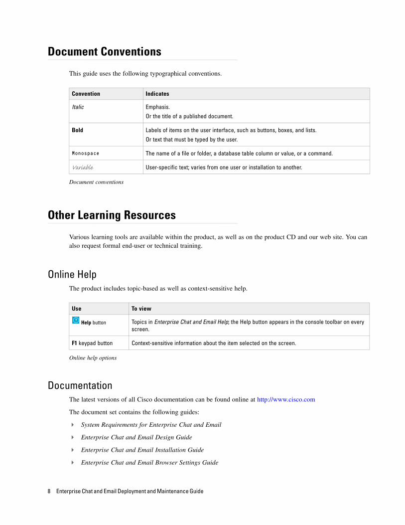
Document Conventions
This guide uses the following typographical conventions.
Document conventions
Other Learning Resources
Various learning tools are available within the product, as well as on the product CD and our web site. You can also request formal end-user or technical training.
Online HelpThe product includes topic-based as well as context-sensitive help.
Online help options
DocumentationThe latest versions of all Cisco documentation can be found online at http://www.cisco.com
The document set contains the following guides:
System Requirements for Enterprise Chat and Email
Enterprise Chat and Email Design Guide
Enterprise Chat and Email Installation Guide
Enterprise Chat and Email Browser Settings Guide
Convention Indicates
Italic Emphasis.
Or the title of a published document.
Bold Labels of items on the user interface, such as buttons, boxes, and lists.
Or text that must be typed by the user.
Monospace The name of a file or folder, a database table column or value, or a command.
Variable User-specific text; varies from one user or installation to another.
Use To view
Help button Topics in Enterprise Chat and Email Help; the Help button appears in the console toolbar on every screen.
F1 keypad button Context-sensitive information about the item selected on the screen.
8 Enterprise Chat and Email Deployment and Maintenance Guide

User Guides for agents and supervisors
Enterprise Chat and Email Agent’s Guide
Enterprise Chat and Email Supervisor’s Guide
User guides for administrators
Enterprise Chat and Email Administrator’s Guide to Administration Console
Enterprise Chat and Email Administrator’s Guide to Routing and Workflows
Enterprise Chat and Email Administrator’s Guide to Chat and Collaboration Resources
Enterprise Chat and Email Administrator’s Guide to Email Resources
Enterprise Chat and Email Administrator’s Guide to Reports Console
Enterprise Chat and Email Administrator’s Guide to System Console
Enterprise Chat and Email Administrator’s Guide to Tools Console
9
Preparing Unified CCE for the Integration
Relationship Between Objects in Unified CCE and ECE
Designing Your Installation
Installing Unified CCE
Setting up Agent Desktops for Voice Call Routing
Configuring Cisco Unified Communication Manager for Routing Voice Calls
Planning Unified CCE and Packaged CCE Configuration
Configuring Unified CCE or Packaged CCE
Installing ECE and the Integration
Configuring the System for Multiple Agent PGs
Configuring Finesse
This chapter provides an overview of the process of setting up an integrated ECE–Unified CCE system. It includes a note about the relationship between objects in the two systems.
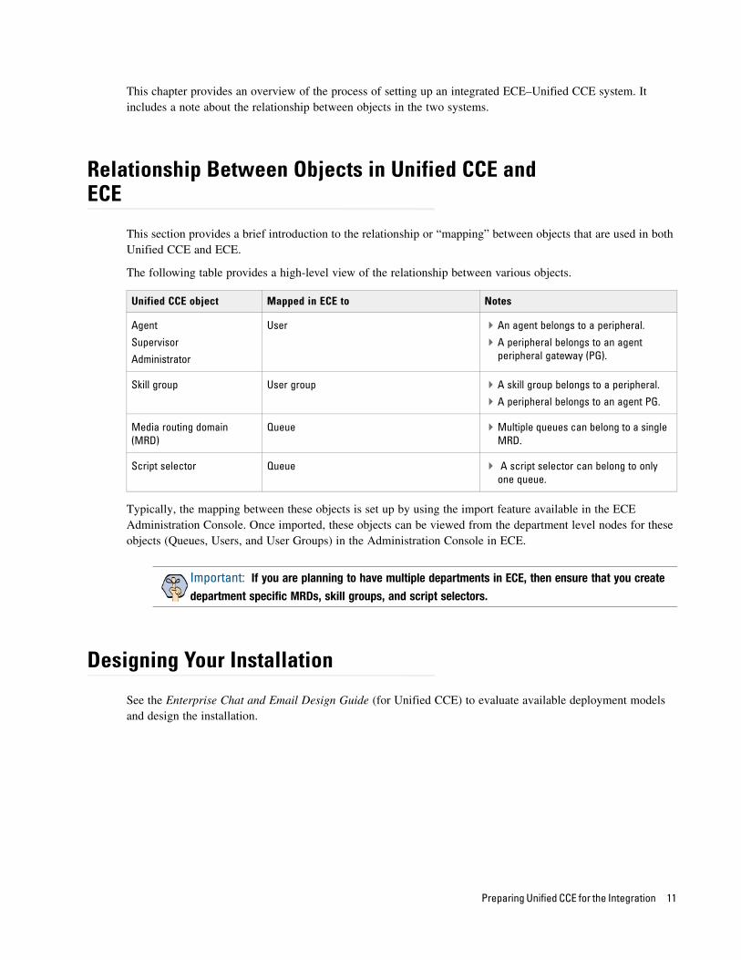
Relationship Between Objects in Unified CCE and ECE
This section provides a brief introduction to the relationship or “mapping” between objects that are used in both Unified CCE and ECE.
The following table provides a high-level view of the relationship between various objects.
Typically, the mapping between these objects is set up by using the import feature available in the ECE Administration Console. Once imported, these objects can be viewed from the department level nodes for these objects (Queues, Users, and User Groups) in the Administration Console in ECE.
Designing Your Installation
See the Enterprise Chat and Email Design Guide (for Unified CCE) to evaluate available deployment models and design the installation.
Unified CCE object Mapped in ECE to Notes
Agent
Supervisor
Administrator
User An agent belongs to a peripheral.
A peripheral belongs to an agent peripheral gateway (PG).
Skill group User group A skill group belongs to a peripheral.
A peripheral belongs to an agent PG.
Media routing domain (MRD)
Queue Multiple queues can belong to a single MRD.
Script selector Queue A script selector can belong to only one queue.
Important: If you are planning to have multiple departments in ECE, then ensure that you create
department specific MRDs, skill groups, and script selectors.
Preparing Unified CCE for the Integration 11
Installing Unified CCE
Ensure that Unified CCE is installed and available for use. Verify that the following items are installed:
Unified CCE Instance
Call Router Side A
Call Router Side B (optional)
Logger Side A
Logger Side B (optional)
Primary Admin Workstation
Secondary Admin Workstation (optional)
Historic Data Server
Network Interface Controllers (NIC) (Only required for Pre-routing)
Agent Peripheral Gateway (Agent PG)
Media Routing Peripheral Gateway (MR PG)
CTI Server
CUIC Database
Java Telephony Application Programming Interface (JTAPI)
Cisco Finesse
See the following documents for help with installing and configuring the system:
Getting Started with Cisco Unified Contact Center Enterprise
Cisco Unified Contact Center Enterprise Installation Guide
Setting up Agent Desktops for Voice Call Routing
Install IP Communicator on each agent’s desktop, or configure an IP phone that communicates with Cisco Unified Communication Manager for the agent. Look at the following links for detailed instructions on installing and configuring IP Communicator and IP phones.
IP Communicator: http://www.cisco.com/en/US/products/sw/voicesw/ps5475/index.html
IP Phone: http://www.cisco.com/en/US/products/hw/phones/ps379/index.html
Important: Skip this section if you are using Packaged CCE.
12 Enterprise Chat and Email Deployment and Maintenance Guide
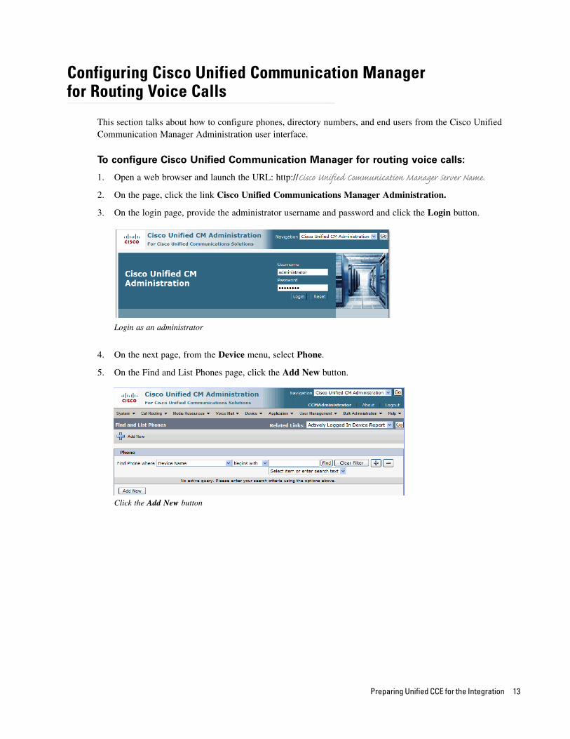
Configuring Cisco Unified Communication Manager for Routing Voice Calls
This section talks about how to configure phones, directory numbers, and end users from the Cisco Unified Communication Manager Administration user interface.
To configure Cisco Unified Communication Manager for routing voice calls:
1. Open a web browser and launch the URL: http://Cisco Unified Communication Manager Server Name.
2. On the page, click the link Cisco Unified Communications Manager Administration.
3. On the login page, provide the administrator username and password and click the Login button.
Login as an administrator
4. On the next page, from the Device menu, select Phone.
5. On the Find and List Phones page, click the Add New button.
Click the Add New button
Preparing Unified CCE for the Integration 13
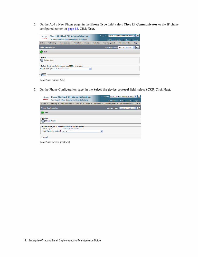
6. On the Add a New Phone page, in the Phone Type field, select Cisco IP Communicator or the IP phone configured earlier on page 12. Click Next.
Select the phone type
7. On the Phone Configuration page, in the Select the device protocol field, select SCCP. Click Next.
Select the device protocol
14 Enterprise Chat and Email Deployment and Maintenance Guide
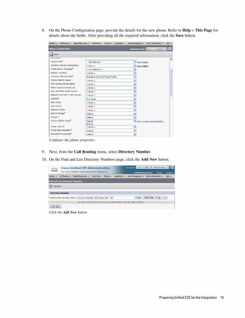
8. On the Phone Configuration page, provide the details for the new phone. Refer to Help > This Page for details about the fields. After providing all the required information, click the Save button.
Configure the phone properties
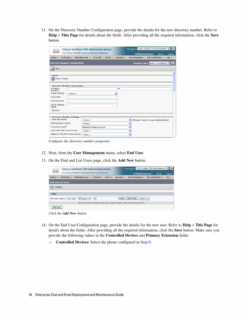
9. Next, from the Call Routing menu, select Directory Number.
10. On the Find and List Directory Numbers page, click the Add New button.
Click the Add New button
Preparing Unified CCE for the Integration 15
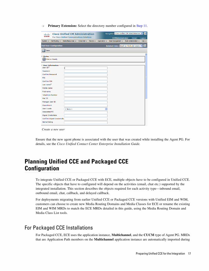
11. On the Directory Number Configuration page, provide the details for the new directory number. Refer to Help > This Page for details about the fields. After providing all the required information, click the Save button.
Configure the directory number properties
12. Next, from the User Management menu, select End User.
13. On the Find and List Users page, click the Add New button.
Click the Add New button
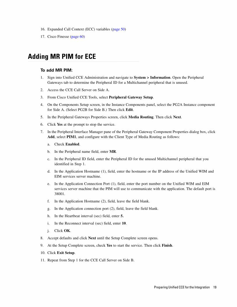
14. On the End User Configuration page, provide the details for the new user. Refer to Help > This Page for details about the fields. After providing all the required information, click the Save button. Make sure you provide the following values in the Controlled Devices and Primary Extension fields.
Controlled Devices: Select the phone configured in Step 8.
16 Enterprise Chat and Email Deployment and Maintenance Guide
Primary Extension: Select the directory number configured in Step 11.
Create a new user
Ensure that the new agent phone is associated with the user that was created while installing the Agent PG. For details, see the Cisco Unified Contact Center Enterprise Installation Guide.
Planning Unified CCE and Packaged CCE Configuration
To integrate Unified CCE or Packaged CCE with ECE, multiple objects have to be configured in Unified CCE. The specific objects that have to configured will depend on the activities (email, chat etc.) supported by the integrated installation. This section describes the objects required for each activity type—inbound email, outbound email, chat, callback, and delayed callback.
For deployments migrating from earlier Unified CCE or Packaged CCE versions with Unified EIM and WIM, customers can choose to create new Media Routing Domains and Media Classes for ECE or rename the existing EIM and WIM MRDs to match the ECE MRDs detailed in this guide, using the Media Routing Domain and Media Class List tools.
For Packaged CCE InstallationsFor Packaged CCE, ECE uses the application instance, Multichannel, and the CUCM type of Agent PG. MRDs that are Application Path members on the Multichannel application instance are automatically imported during
Preparing Unified CCE for the Integration 17

installation. Agents and skill groups, which belong to the CUCM type of Agent PG are imported during installation.
Unified and Packaged CCE customers who intend to use ECE must access Peripheral Gateway Setup on both CCE Call Servers to set up a Multichannel PIM that associates ECE with the MR PG (PG2). See “Adding MR PIM for ECE” on page 19.
In addition to this, objects listed in this section should be configured in Packaged CCE.
The following objects must be configured in the order in which they are presented here. For configuration details, refer to the following section: “Configuring Unified CCE or Packaged CCE” on page 20.
1. Call type (page 27)
2. Application path (page 36)
3. Agents (page 39)
4. Skill groups (page 40)
5. Script selector (page 42)
6. Scripts (Not required for outbound email activities) (page 44)
7. Device target (Not required for inbound email, outbound email, and chat activities) (page 49)
8. Cisco Finesse (page 60)
For Unified CCE InstallationsThe following objects must be configured in the order in which they are presented here. For configuration details, refer to the following section: “Configuring Unified CCE or Packaged CCE” on page 20.
1. Application instance (page 20)
2. Media classes (page 22)
3. Media routing domains (MRD) (page 23)
4. Network voice response unit (Network VRU) (Not required for outbound email activities) (page 25)
5. Network voice response unit script (Network VRU script) (Not required for inbound email and outbound email activities) (page 26)
6. Call type (page 27)
7. Media routing peripheral gateway (MR PG) (page 28)
8. Agent desk settings (page 32)
9. Agent peripheral gateway (Agent PG) (page 33)
10. Application path (page 36)
11. Agents (page 39)
12. Skill groups (page 40)
13. Script selector (page 42)
14. Scripts (Not required for outbound email activities) (page 44)
15. Device target (Not required for inbound email, outbound email, and chat activities) (page 49)
18 Enterprise Chat and Email Deployment and Maintenance Guide
16. Expanded Call Context (ECC) variables (page 50)
17. Cisco Finesse (page 60)
Adding MR PIM for ECE
To add MR PIM:
1. Sign into Unified CCE Administration and navigate to System > Information. Open the Peripheral Gateways tab to determine the Peripheral ID for a Multichannel peripheral that is unused.
2. Access the CCE Call Server on Side A.
3. From Cisco Unified CCE Tools, select Peripheral Gateway Setup.
4. On the Components Setup screen, in the Instance Components panel, select the PG2A Instance component for Side A. (Select PG2B for Side B.) Then click Edit.
5. In the Peripheral Gateways Properties screen, click Media Routing. Then click Next.
6. Click Yes at the prompt to stop the service.
7. In the Peripheral Interface Manager pane of the Peripheral Gateway Component Properties dialog box, click Add, select PIM1, and configure with the Client Type of Media Routing as follows:
a. Check Enabled.
b. In the Peripheral name field, enter MR.
c. In the Peripheral ID field, enter the Peripheral ID for the unused Multichannel peripheral that you identified in Step 1.
d. In the Application Hostname (1), field, enter the hostname or the IP address of the Unified WIM and EIM services server machine.
e. In the Application Connection Port (1), field, enter the port number on the Unified WIM and EIM services server machine that the PIM will use to communicate with the application. The default port is 38001.
f. In the Application Hostname (2), field, leave the field blank.
g. In the Application connection port (2), field, leave the field blank.
h. In the Heartbeat interval (sec) field, enter 5.
i. In the Reconnect interval (sec) field, enter 10.
j. Click OK.
8. Accept defaults and click Next until the Setup Complete screen opens.
9. At the Setup Complete screen, check Yes to start the service. Then click Finish.
10. Click Exit Setup.
11. Repeat from Step 1 for the CCE Call Server on Side B.
Preparing Unified CCE for the Integration 19
Adding ECE to Packaged CCE Inventory
Deployments using ECE with Packaged CCE must add ECE to the system inventory as an external machine.
To add ECE
1. Navigate to Web Administration > System > Deployment.
2. Click Add Machine.
3. Select Enterprise Chat and Email from the drop-down list.
4. Add the name.
5. Add the hostname or IP address of the ECE Services Server.
6. Click Save.
Configuring Unified CCE or Packaged CCE
This section describes the process of configuring Unified CCE objects that are required for the integration with ECE. These objects must be configured in the order in which they are presented here. For details of these objects refer to the Online Help and printed documentation for Unified CCE.
Most of the tasks in this section are explained using the desktop version of the Configuration Manager. For Packaged CCE, you will perform these tasks using the CCE Web Administration page.
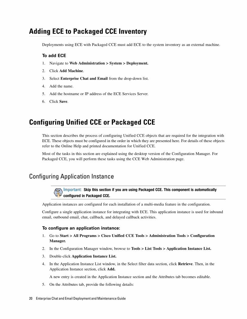
Configuring Application Instance
Application instances are configured for each installation of a multi-media feature in the configuration.
Configure a single application instance for integrating with ECE. This application instance is used for inbound email, outbound email, chat, callback, and delayed callback activities.
To configure an application instance:
1. Go to Start > All Programs > Cisco Unified CCE Tools > Administration Tools > Configuration Manager.
2. In the Configuration Manager window, browse to Tools > List Tools > Application Instance List.
3. Double-click Application Instance List.
4. In the Application Instance List window, in the Select filter data section, click Retrieve. Then, in the Application Instance section, click Add.
A new entry is created in the Application Instance section and the Attributes tab becomes editable.
5. On the Attributes tab, provide the following details:
Important: Skip this section if you are using Packaged CCE. This component is automatically
configured in Packaged CCE.
20 Enterprise Chat and Email Deployment and Maintenance Guide
Name: Provide a name for the application instance.
Application key: Provide a unique value for the key. Please note that ECE uses the application instance name and not the application key to connect to Unified CCE.
Application type: Set it to <Other>.
Permission level: Set it to Read only.
Click Save.
Configure the application instance
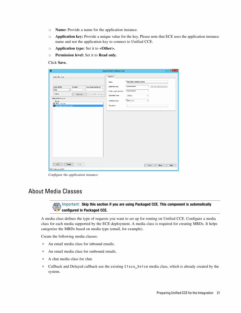
About Media Classes
A media class defines the type of requests you want to set up for routing on Unified CCE. Configure a media class for each media supported by the ECE deployment. A media class is required for creating MRDs. It helps categorize the MRDs based on media type (email, for example).
Create the following media classes:
An email media class for inbound emails.
An email media class for outbound emails.
A chat media class for chat.
Callback and Delayed callback use the existing Cisco_Voice media class, which is already created by the system.
Important: Skip this section if you are using Packaged CCE. This component is automatically
configured in Packaged CCE.
Preparing Unified CCE for the Integration 21
Once a media-class for a particular media is created, all other objects required for that media class must also be configured.
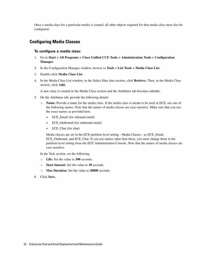
Configuring Media Classes
To configure a media class:
1. Go to Start > All Programs > Cisco Unified CCE Tools > Administration Tools > Configuration Manager.
2. In the Configuration Manager window, browse to Tools > List Tools > Media Class List.
3. Double-click Media Class List.
4. In the Media Class List window, in the Select filter data section, click Retrieve. Then, in the Media Class section, click Add.
A new entry is created in the Media Class section and the Attributes tab becomes editable.
5. On the Attributes tab, provide the following details:
Name: Provide a name for the media class. If the media class is meant to be used in ECE, use one of the following names. Note that the names of media classes are case sensitive. Make sure that you use the exact names as provided here.
ECE_Email (for inbound email)
ECE_Outbound (for outbound email)
ECE_Chat (for chat)
Media classes are set in the ECE partition level setting - Media Classes - as ECE_Email, ECE_Outbound, and ECE_Chat. If you use names other than these, you must change them in the partition level setting from the ECE Administration Console. Note that the names of media classes are case sensitive.
In the Task section, set the following.
Life: Set the value to 300 seconds.
Start timeout: Set the value to 30 seconds.
Max Duration: Set the value to 28800 seconds.
6. Click Save.
22 Enterprise Chat and Email Deployment and Maintenance Guide
Configure media classes
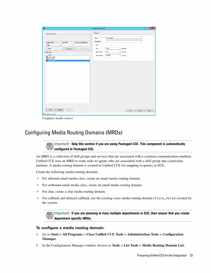
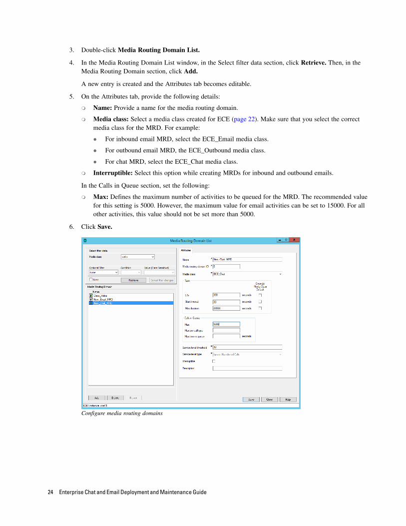
Configuring Media Routing Domains (MRDs)
An MRD is a collection of skill groups and services that are associated with a common communication medium. Unified CCE uses an MRD to route tasks to agents who are associated with a skill group and a particular medium. A media routing domain is created in Unified CCE for mapping to queues in ECE.
Create the following media routing domains:
For inbound email media class, create an email media routing domain.
For outbound email media class, create an email media routing domain.
For chat, create a chat media routing domain.
For callback and delayed callback, use the existing voice media routing domain (Cisco_Voice) created by the system.
To configure a media routing domain:
1. Go to Start > All Programs > Cisco Unified CCE Tools > Administration Tools > Configuration Manager.
2. In the Configuration Manager window, browse to Tools > List Tools > Media Routing Domain List.
Important: Skip this section if you are using Packaged CCE. This component is automatically
configured in Packaged CCE.
Important: If you are planning to have multiple departments in ECE, then ensure that you create
department specific MRDs.
Preparing Unified CCE for the Integration 23
3. Double-click Media Routing Domain List.
4. In the Media Routing Domain List window, in the Select filter data section, click Retrieve. Then, in the Media Routing Domain section, click Add.
A new entry is created and the Attributes tab becomes editable.
5. On the Attributes tab, provide the following details:
Name: Provide a name for the media routing domain.
Media class: Select a media class created for ECE (page 22). Make sure that you select the correct media class for the MRD. For example:
For inbound email MRD, select the ECE_Email media class.
For outbound email MRD, the ECE_Outbound media class.
For chat MRD, select the ECE_Chat media class.
Interruptible: Select this option while creating MRDs for inbound and outbound emails.
In the Calls in Queue section, set the following:
Max: Defines the maximum number of activities to be queued for the MRD. The recommended value for this setting is 5000. However, the maximum value for email activities can be set to 15000. For all other activities, this value should not be set more than 5000.
6. Click Save.
Configure media routing domains
24 Enterprise Chat and Email Deployment and Maintenance Guide
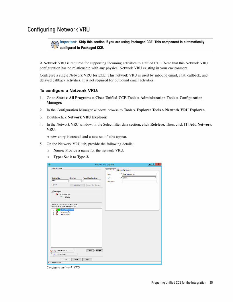
Configuring Network VRU
A Network VRU is required for supporting incoming activities to Unified CCE. Note that this Network VRU configuration has no relationship with any physical Network VRU existing in your environment.
Configure a single Network VRU for ECE. This network VRU is used by inbound email, chat, callback, and delayed callback activities. It is not required for outbound email activities.
To configure a Network VRU:
1. Go to Start > All Programs > Cisco Unified CCE Tools > Administration Tools > Configuration Manager.
2. In the Configuration Manager window, browse to Tools > Explorer Tools > Network VRU Explorer.
3. Double-click Network VRU Explorer.
4. In the Network VRU window, in the Select filter data section, click Retrieve. Then, click [1] Add Network VRU.
A new entry is created and a new set of tabs appear.
5. On the Network VRU tab, provide the following details:
Name: Provide a name for the network VRU.
Type: Set it to Type 2.
Configure network VRU
Important: Skip this section if you are using Packaged CCE. This component is automatically
configured in Packaged CCE.
Preparing Unified CCE for the Integration 25
6. Click Save.
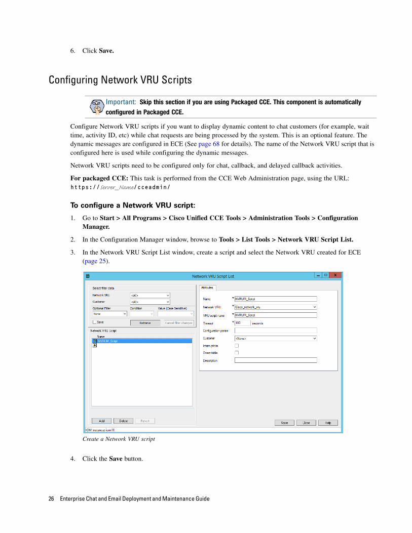
Configuring Network VRU Scripts
Configure Network VRU scripts if you want to display dynamic content to chat customers (for example, wait time, activity ID, etc) while chat requests are being processed by the system. This is an optional feature. The dynamic messages are configured in ECE (See page 68 for details). The name of the Network VRU script that is configured here is used while configuring the dynamic messages.
Network VRU scripts need to be configured only for chat, callback, and delayed callback activities.
For packaged CCE: This task is performed from the CCE Web Administration page, using the URL: https://Server_Name/cceadmin/
To configure a Network VRU script:
1. Go to Start > All Programs > Cisco Unified CCE Tools > Administration Tools > Configuration Manager.
2. In the Configuration Manager window, browse to Tools > List Tools > Network VRU Script List.
3. In the Network VRU Script List window, create a script and select the Network VRU created for ECE (page 25).
Create a Network VRU script
4. Click the Save button.
Important: Skip this section if you are using Packaged CCE. This component is automatically
configured in Packaged CCE.
26 Enterprise Chat and Email Deployment and Maintenance Guide
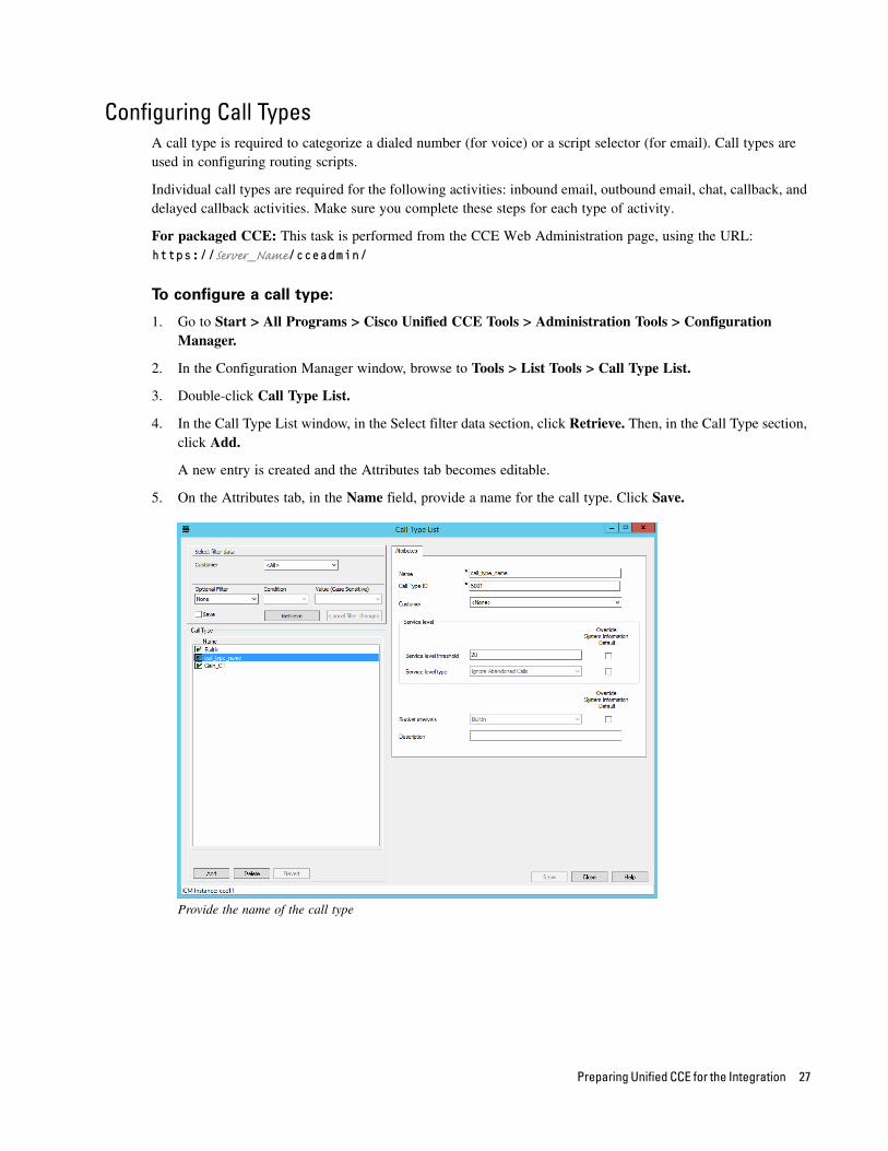
Configuring Call TypesA call type is required to categorize a dialed number (for voice) or a script selector (for email). Call types are used in configuring routing scripts.
Individual call types are required for the following activities: inbound email, outbound email, chat, callback, and delayed callback activities. Make sure you complete these steps for each type of activity.
For packaged CCE: This task is performed from the CCE Web Administration page, using the URL: https://Server_Name/cceadmin/
To configure a call type:
1. Go to Start > All Programs > Cisco Unified CCE Tools > Administration Tools > Configuration Manager.
2. In the Configuration Manager window, browse to Tools > List Tools > Call Type List.
3. Double-click Call Type List.
4. In the Call Type List window, in the Select filter data section, click Retrieve. Then, in the Call Type section, click Add.
A new entry is created and the Attributes tab becomes editable.
5. On the Attributes tab, in the Name field, provide a name for the call type. Click Save.
Provide the name of the call type
Preparing Unified CCE for the Integration 27
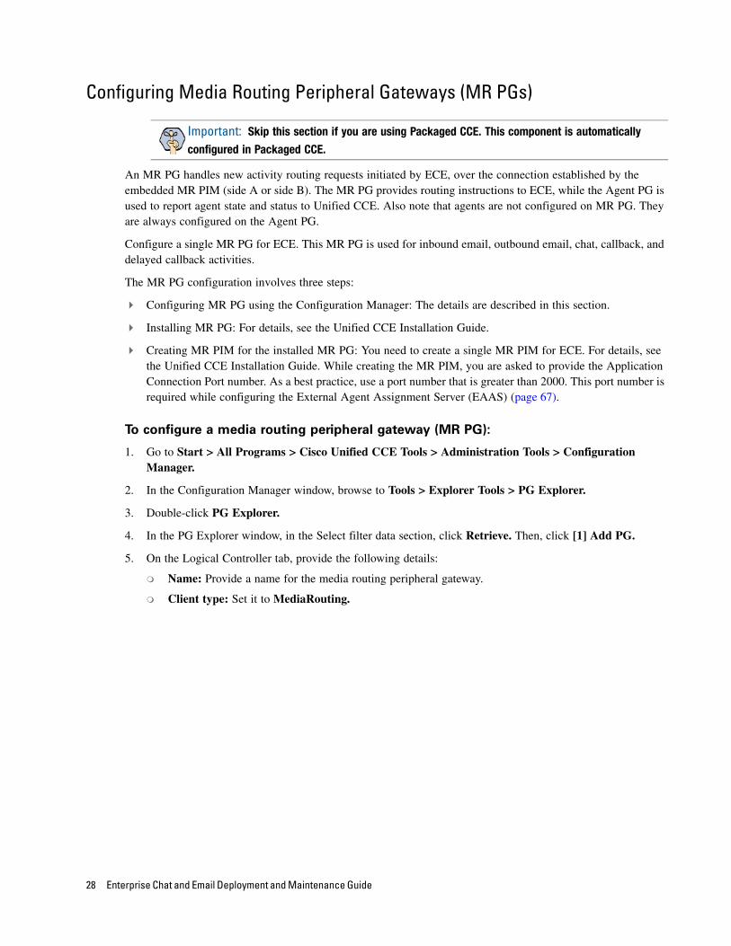
Configuring Media Routing Peripheral Gateways (MR PGs)
An MR PG handles new activity routing requests initiated by ECE, over the connection established by the embedded MR PIM (side A or side B). The MR PG provides routing instructions to ECE, while the Agent PG is used to report agent state and status to Unified CCE. Also note that agents are not configured on MR PG. They are always configured on the Agent PG.
Configure a single MR PG for ECE. This MR PG is used for inbound email, outbound email, chat, callback, and delayed callback activities.
The MR PG configuration involves three steps:
Configuring MR PG using the Configuration Manager: The details are described in this section.
Installing MR PG: For details, see the Unified CCE Installation Guide.
Creating MR PIM for the installed MR PG: You need to create a single MR PIM for ECE. For details, see the Unified CCE Installation Guide. While creating the MR PIM, you are asked to provide the Application Connection Port number. As a best practice, use a port number that is greater than 2000. This port number is required while configuring the External Agent Assignment Server (EAAS) (page 67).
To configure a media routing peripheral gateway (MR PG):
1. Go to Start > All Programs > Cisco Unified CCE Tools > Administration Tools > Configuration Manager.
2. In the Configuration Manager window, browse to Tools > Explorer Tools > PG Explorer.
3. Double-click PG Explorer.
4. In the PG Explorer window, in the Select filter data section, click Retrieve. Then, click [1] Add PG.
5. On the Logical Controller tab, provide the following details:
Name: Provide a name for the media routing peripheral gateway.
Client type: Set it to MediaRouting.
Important: Skip this section if you are using Packaged CCE. This component is automatically
configured in Packaged CCE.
28 Enterprise Chat and Email Deployment and Maintenance Guide
Configure an MR PG
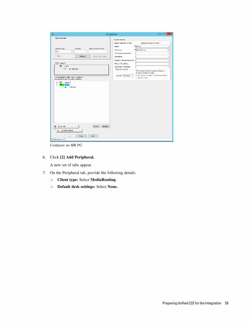
6. Click [2] Add Peripheral.
A new set of tabs appear.
7. On the Peripheral tab, provide the following details:
Client type: Select MediaRouting.
Default desk settings: Select None.
Preparing Unified CCE for the Integration 29
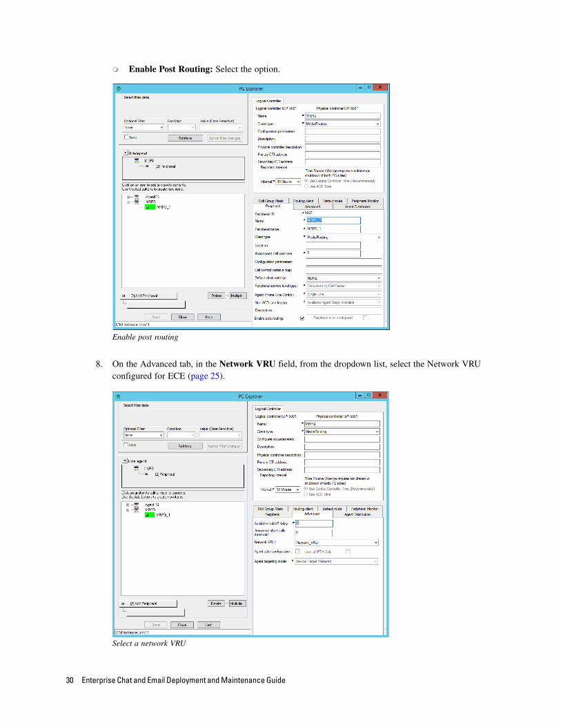
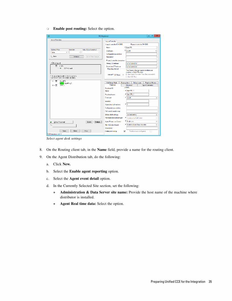
Enable Post Routing: Select the option.
Enable post routing
8. On the Advanced tab, in the Network VRU field, from the dropdown list, select the Network VRU configured for ECE (page 25).
Select a network VRU
30 Enterprise Chat and Email Deployment and Maintenance Guide
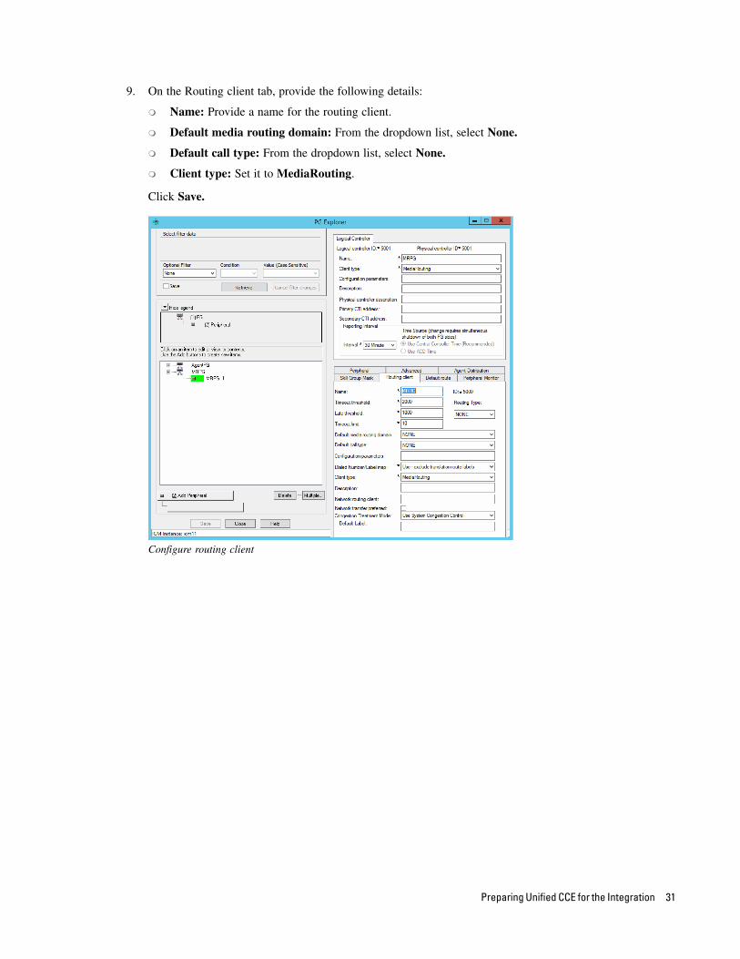
9. On the Routing client tab, provide the following details:
Name: Provide a name for the routing client.
Default media routing domain: From the dropdown list, select None.
Default call type: From the dropdown list, select None.
Client type: Set it to MediaRouting.
Click Save.
Configure routing client
Preparing Unified CCE for the Integration 31
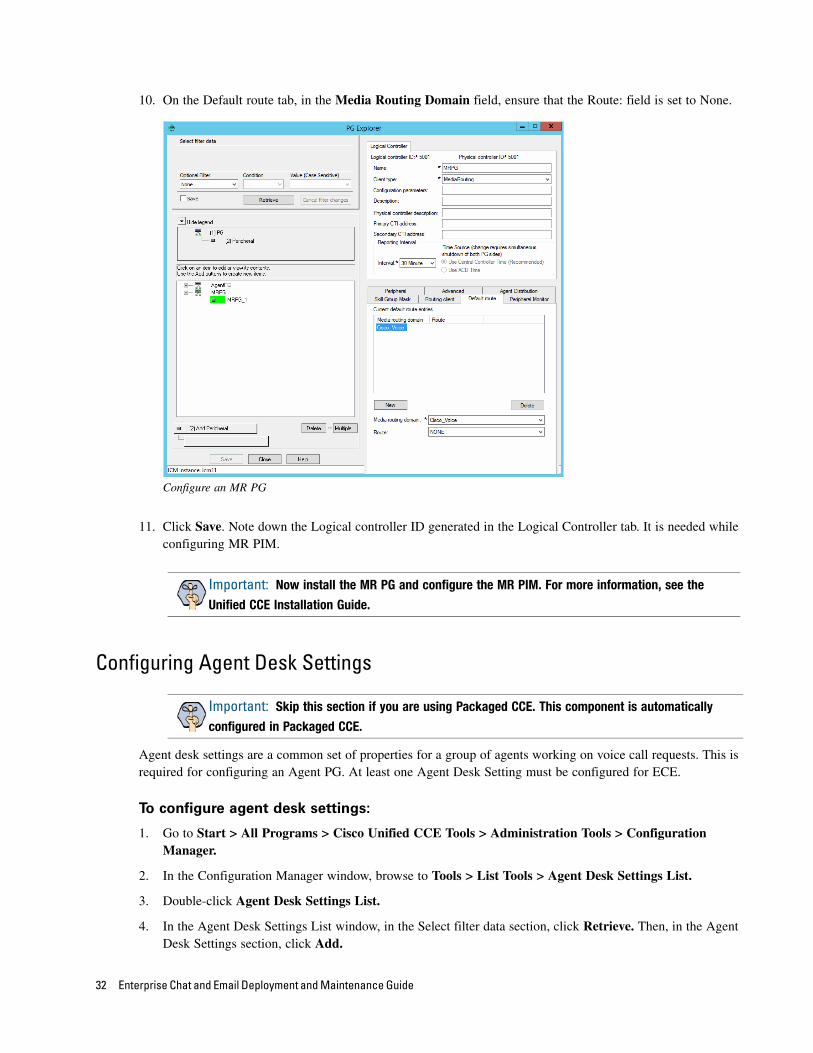
10. On the Default route tab, in the Media Routing Domain field, ensure that the Route: field is set to None.
Configure an MR PG
11. Click Save. Note down the Logical controller ID generated in the Logical Controller tab. It is needed while configuring MR PIM.
Configuring Agent Desk Settings
Agent desk settings are a common set of properties for a group of agents working on voice call requests. This is required for configuring an Agent PG. At least one Agent Desk Setting must be configured for ECE.
To configure agent desk settings:
1. Go to Start > All Programs > Cisco Unified CCE Tools > Administration Tools > Configuration Manager.
2. In the Configuration Manager window, browse to Tools > List Tools > Agent Desk Settings List.
3. Double-click Agent Desk Settings List.
4. In the Agent Desk Settings List window, in the Select filter data section, click Retrieve. Then, in the Agent Desk Settings section, click Add.
Important: Now install the MR PG and configure the MR PIM. For more information, see the
Unified CCE Installation Guide.
Important: Skip this section if you are using Packaged CCE. This component is automatically
configured in Packaged CCE.
32 Enterprise Chat and Email Deployment and Maintenance Guide
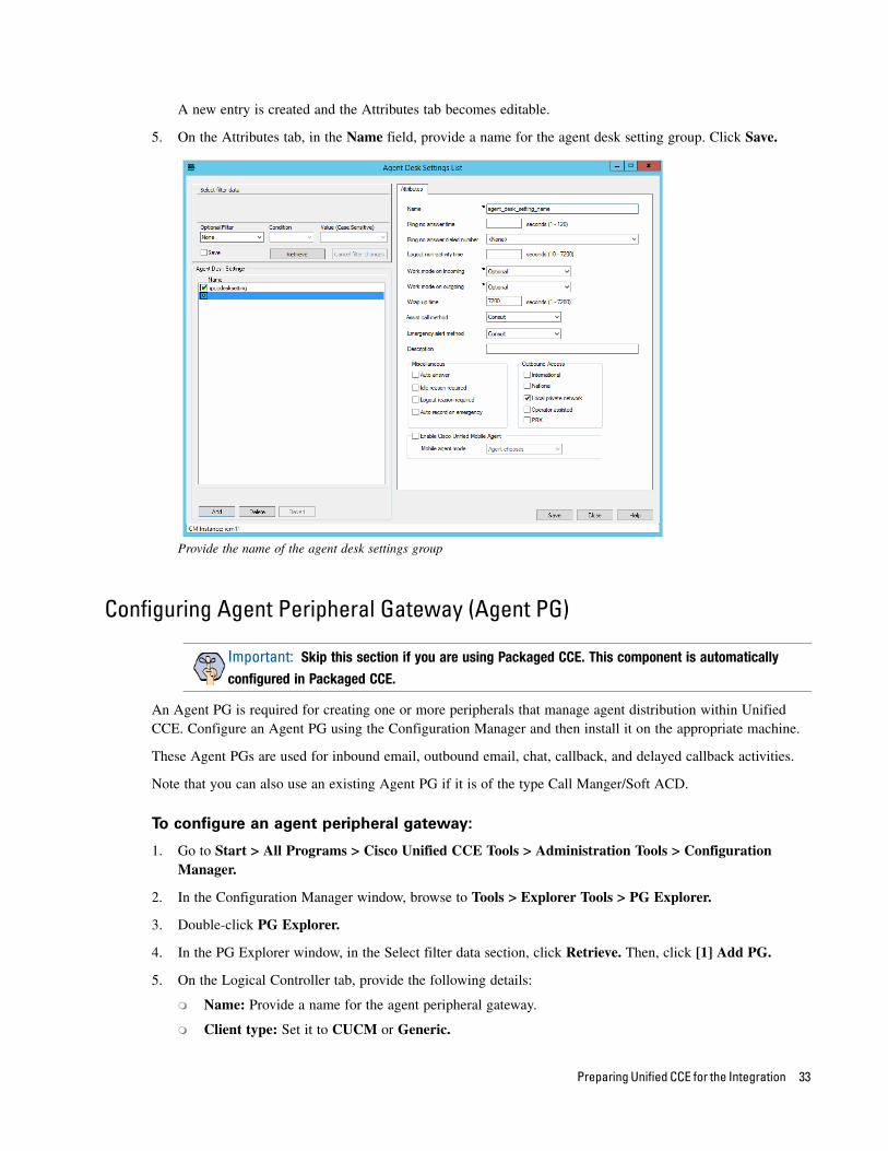
A new entry is created and the Attributes tab becomes editable.
5. On the Attributes tab, in the Name field, provide a name for the agent desk setting group. Click Save.
Provide the name of the agent desk settings group
Configuring Agent Peripheral Gateway (Agent PG)
An Agent PG is required for creating one or more peripherals that manage agent distribution within Unified CCE. Configure an Agent PG using the Configuration Manager and then install it on the appropriate machine.
These Agent PGs are used for inbound email, outbound email, chat, callback, and delayed callback activities.
Note that you can also use an existing Agent PG if it is of the type Call Manger/Soft ACD.
To configure an agent peripheral gateway:
1. Go to Start > All Programs > Cisco Unified CCE Tools > Administration Tools > Configuration Manager.
2. In the Configuration Manager window, browse to Tools > Explorer Tools > PG Explorer.
3. Double-click PG Explorer.
4. In the PG Explorer window, in the Select filter data section, click Retrieve. Then, click [1] Add PG.
5. On the Logical Controller tab, provide the following details:
Name: Provide a name for the agent peripheral gateway.
Client type: Set it to CUCM or Generic.
Important: Skip this section if you are using Packaged CCE. This component is automatically
configured in Packaged CCE.
Preparing Unified CCE for the Integration 33
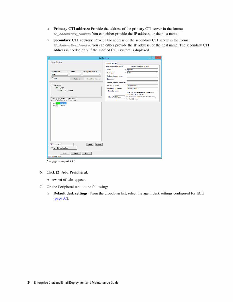
Primary CTI address: Provide the address of the primary CTI server in the format IP_Address:Port_Number. You can either provide the IP address, or the host name.
Secondary CTI address: Provide the address of the secondary CTI server in the format IP_Address:Port_Number. You can either provide the IP address, or the host name. The secondary CTI address is needed only if the Unified CCE system is duplexed.
Configure agent PG
6. Click [2] Add Peripheral.
A new set of tabs appear.
7. On the Peripheral tab, do the following:
Default desk settings: From the dropdown list, select the agent desk settings configured for ECE (page 32).
34 Enterprise Chat and Email Deployment and Maintenance Guide
Enable post routing: Select the option.
Select agent desk settings
8. On the Routing client tab, in the Name field, provide a name for the routing client.
9. On the Agent Distribution tab, do the following:
a. Click New.
b. Select the Enable agent reporting option.
c. Select the Agent event detail option.
d. In the Currently Selected Site section, set the following:
Administration & Data Server site name: Provide the host name of the machine where distributor is installed.
Agent Real time data: Select the option.
Preparing Unified CCE for the Integration 35
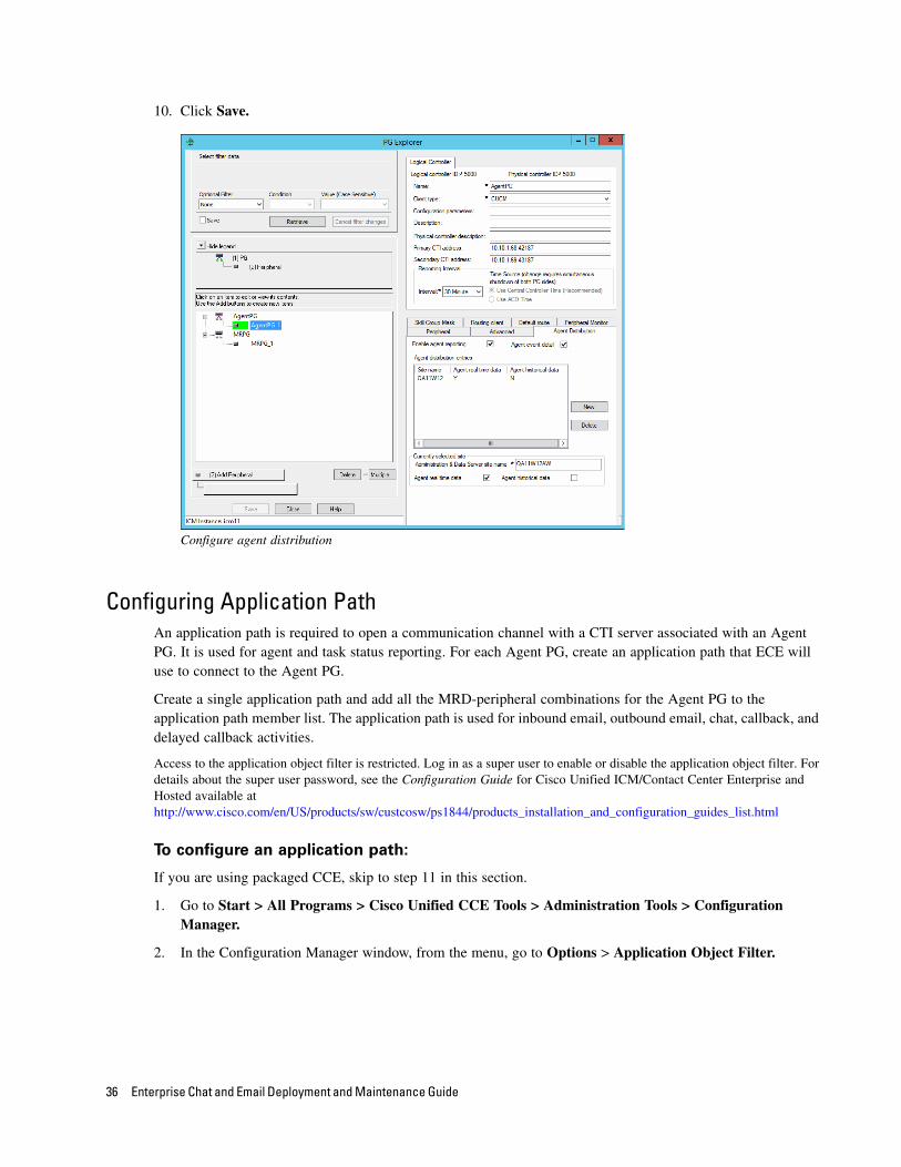
10. Click Save.
Configure agent distribution
Configuring Application PathAn application path is required to open a communication channel with a CTI server associated with an Agent PG. It is used for agent and task status reporting. For each Agent PG, create an application path that ECE will use to connect to the Agent PG.
Create a single application path and add all the MRD-peripheral combinations for the Agent PG to the application path member list. The application path is used for inbound email, outbound email, chat, callback, and delayed callback activities.
Access to the application object filter is restricted. Log in as a super user to enable or disable the application object filter. For details about the super user password, see the Configuration Guide for Cisco Unified ICM/Contact Center Enterprise and Hosted available at http://www.cisco.com/en/US/products/sw/custcosw/ps1844/products_installation_and_configuration_guides_list.html
To configure an application path:
If you are using packaged CCE, skip to step 11 in this section.
1. Go to Start > All Programs > Cisco Unified CCE Tools > Administration Tools > Configuration Manager.
2. In the Configuration Manager window, from the menu, go to Options > Application Object Filter.
36 Enterprise Chat and Email Deployment and Maintenance Guide
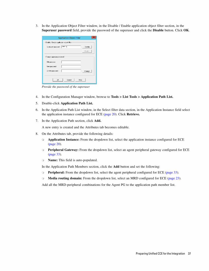
3. In the Application Object Filter window, in the Disable / Enable application object filter section, in the Superuser password field, provide the password of the superuser and click the Disable button. Click OK.
Provide the password of the superuser
4. In the Configuration Manager window, browse to Tools > List Tools > Application Path List.
5. Double-click Application Path List.
6. In the Application Path List window, in the Select filter data section, in the Application Instance field select the application instance configured for ECE (page 20). Click Retrieve.
7. In the Application Path section, click Add.
A new entry is created and the Attributes tab becomes editable.
8. On the Attributes tab, provide the following details:
Application Instance: From the dropdown list, select the application instance configured for ECE (page 20).
Peripheral Gateway: From the dropdown list, select an agent peripheral gateway configured for ECE (page 33).
Name: This field is auto-populated.
In the Application Path Members section, click the Add button and set the following:
Peripheral: From the dropdown list, select the agent peripheral configured for ECE (page 33).
Media routing domain: From the dropdown list, select an MRD configured for ECE (page 23).
Add all the MRD-peripheral combinations for the Agent PG to the application path member list.
Preparing Unified CCE for the Integration 37
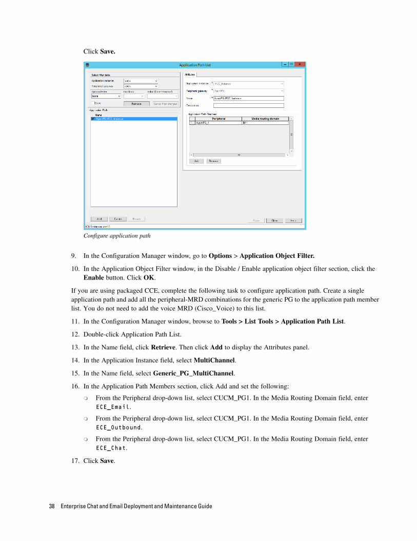
Click Save.
Configure application path
9. In the Configuration Manager window, go to Options > Application Object Filter.
10. In the Application Object Filter window, in the Disable / Enable application object filter section, click the Enable button. Click OK.
If you are using packaged CCE, complete the following task to configure application path. Create a single application path and add all the peripheral-MRD combinations for the generic PG to the application path member list. You do not need to add the voice MRD (Cisco_Voice) to this list.
11. In the Configuration Manager window, browse to Tools > List Tools > Application Path List.
12. Double-click Application Path List.
13. In the Name field, click Retrieve. Then click Add to display the Attributes panel.
14. In the Application Instance field, select MultiChannel.
15. In the Name field, select Generic_PG_MultiChannel.
16. In the Application Path Members section, click Add and set the following:
From the Peripheral drop-down list, select CUCM_PG1. In the Media Routing Domain field, enter ECE_Email.
From the Peripheral drop-down list, select CUCM_PG1. In the Media Routing Domain field, enter ECE_Outbound.
From the Peripheral drop-down list, select CUCM_PG1. In the Media Routing Domain field, enter ECE_Chat.
17. Click Save.
38 Enterprise Chat and Email Deployment and Maintenance Guide
Configuring AgentsAn agent is created in Unified CCE for mapping to users in ECE. Create all agents for whom routing or reporting is done in Unified CCE. If you plan to use Precision Routing, you need to assign attributes to agents. For details, see “Assigning Attributes to Agents” on page 53.
Create agents for handling inbound email, outbound email, chat, callback, and delayed callback activities.
For packaged CCE: This task is performed from the CCE Web Administration page, using the URL: https://Server_Name/cceadmin/
To configure an agent:
1. Go to Start > All Programs > Cisco Unified CCE Tools > Administration Tools > Configuration Manager.
2. In the Configuration Manager window, browse to Tools > Explorer Tools > Agent Explorer.
3. Double-click Agent Explorer.
4. In the Agent Explorer window, in the Select filter data section, in the Peripheral field select an agent peripheral. Click Retrieve.
5. Click the [1]Add Agent button.
A new entry is created and a new set of tabs appear.
6. On the Agent tab, provide the following details:
Enable logins: Select the option.
Enable Single sign-on (SSO): Select this option if you want to use single sign-on for the agent. Password fields are disabled if you select this option.
First name: Provide the first name.
Last name: Provide the last name.
Login name: Provide the login name for the agent. For callback and delayed callback agents, the login name should match the User ID provided while configuring End users from the Cisco Unified Communication Manager Administration user interface (page 16).
Password: Provide the password for the agent. Make sure the password does not contain the following characters: = (equal to) and ; (semicolon) as ECE does not allow the users to login if these characters are present in the passwords. Password fields are disabled if single sign-on option is selected for the agent.
Enterprise name: This field is auto-populated.
7. Click Save.
Preparing Unified CCE for the Integration 39
Configure an agent
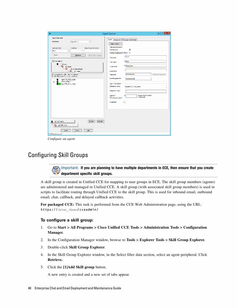
Configuring Skill Groups
A skill group is created in Unified CCE for mapping to user groups in ECE. The skill group members (agents) are administered and managed in Unified CCE. A skill group (with associated skill group members) is used in scripts to facilitate routing through Unified CCE to the skill group. This is used for inbound email, outbound email, chat, callback, and delayed callback activities.
For packaged CCE: This task is performed from the CCE Web Administration page, using the URL: https://Server_Name/cceadmin/
To configure a skill group:
1. Go to Start > All Programs > Cisco Unified CCE Tools > Administration Tools > Configuration Manager.
2. In the Configuration Manager window, browse to Tools > Explorer Tools > Skill Group Explorer.
3. Double-click Skill Group Explorer.
4. In the Skill Group Explorer window, in the Select filter data section, select an agent peripheral. Click Retrieve.
5. Click the [1]Add Skill group button.
A new entry is created and a new set of tabs appear.
Important: If you are planning to have multiple departments in ECE, then ensure that you create
department specific skill groups.
40 Enterprise Chat and Email Deployment and Maintenance Guide
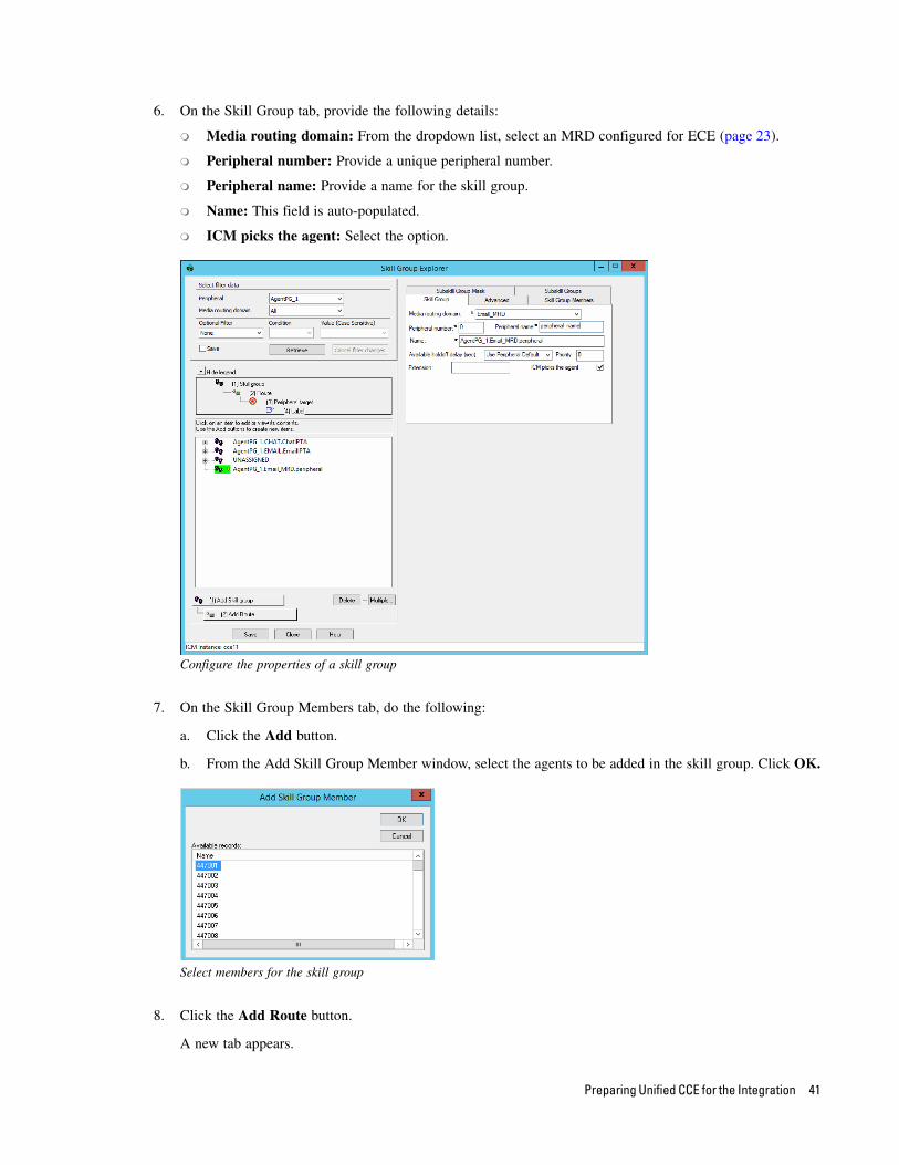
6. On the Skill Group tab, provide the following details:
Media routing domain: From the dropdown list, select an MRD configured for ECE (page 23).
Peripheral number: Provide a unique peripheral number.
Peripheral name: Provide a name for the skill group.
Name: This field is auto-populated.
ICM picks the agent: Select the option.
Configure the properties of a skill group
7. On the Skill Group Members tab, do the following:
a. Click the Add button.
b. From the Add Skill Group Member window, select the agents to be added in the skill group. Click OK.
Select members for the skill group
8. Click the Add Route button.
A new tab appears.
Preparing Unified CCE for the Integration 41
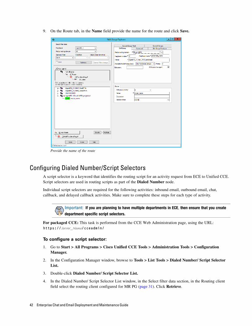
9. On the Route tab, in the Name field provide the name for the route and click Save.
Provide the name of the route
Configuring Dialed Number/Script SelectorsA script selector is a keyword that identifies the routing script for an activity request from ECE to Unified CCE. Script selectors are used in routing scripts as part of the Dialed Number node.
Individual script selectors are required for the following activities: inbound email, outbound email, chat, callback, and delayed callback activities. Make sure to complete these steps for each type of activity.
For packaged CCE: This task is performed from the CCE Web Administration page, using the URL: https://Server_Name/cceadmin/
To configure a script selector:
1. Go to Start > All Programs > Cisco Unified CCE Tools > Administration Tools > Configuration Manager.
2. In the Configuration Manager window, browse to Tools > List Tools > Dialed Number/ Script Selector List.
3. Double-click Dialed Number/ Script Selector List.
4. In the Dialed Number/ Script Selector List window, in the Select filter data section, in the Routing client field select the routing client configured for MR PG (page 31). Click Retrieve.
Important: If you are planning to have multiple departments in ECE, then ensure that you create
department specific script selectors.
42 Enterprise Chat and Email Deployment and Maintenance Guide
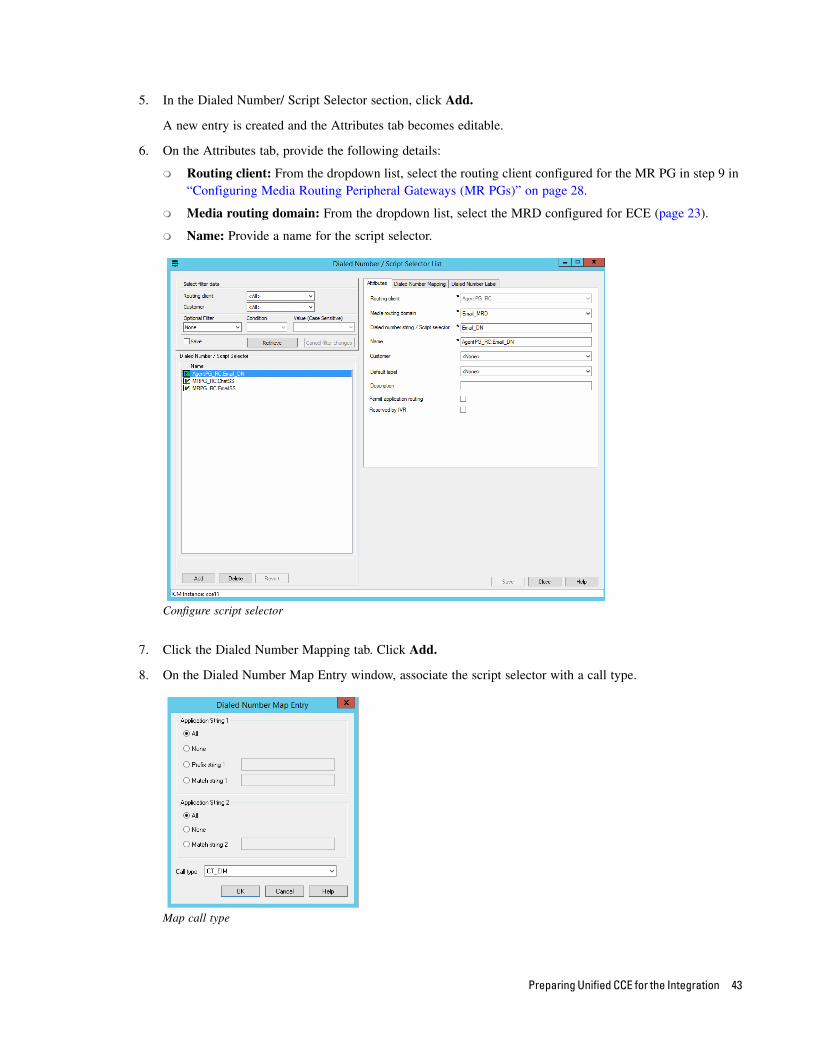
5. In the Dialed Number/ Script Selector section, click Add.
A new entry is created and the Attributes tab becomes editable.
6. On the Attributes tab, provide the following details:
Routing client: From the dropdown list, select the routing client configured for the MR PG in step 9 in “Configuring Media Routing Peripheral Gateways (MR PGs)” on page 28.
Media routing domain: From the dropdown list, select the MRD configured for ECE (page 23).
Name: Provide a name for the script selector.
Configure script selector
7. Click the Dialed Number Mapping tab. Click Add.
8. On the Dialed Number Map Entry window, associate the script selector with a call type.
Map call type
Preparing Unified CCE for the Integration 43
9. Click OK to save the entry. Then click Save to save the script selector configuration.
Creating ScriptsA routing script determines the path and target object for an activity routed from ECE to Unified CCE. Individual routing scripts are required for the following activities: inbound email, chat, callback, and delayed callback activities. Make sure to complete these steps for all these activities. You do not need routing scripts for outbound email activities.
Universal queues and Precision queues can be used in the scripts configured for ECE. Precision queues cannot be used if you are using Unified CCE 11.0(1) version.
For details about creating universal queues, see the Scripting and Media Routing Guide for Unified CCE available at http://www.cisco.com/en/US/products/sw/custcosw/ps1844/products_user_guide_list.html. Make sure to use the guide that matches the version of the product that you are using. To find the right version, refer to the Cisco Unified Contact Center Enterprise (Unified CCE) Software Compatibility Guide available at http://www.cisco.com/en/US/products/sw/custcosw/ps1844/products_device_support_tables_list.html.
For details about configuring Precision Routing, see “Configuring Precision Routing” on page 52.
To use the Personalized Activity Assignment feature available in ECE, you need to create some addition objects (Enterprise Skill Groups and Enterprise Routes) and the scripts need to be configured a certain way. For details, see “Creating Objects in Unified CCE for Personalized Activity Assignment” on page 55.
The following procedure shows how to set up a particular script. To find out more about setting up different types of scripts to meet your routing requirements, see the Scripting and Media Routing Guide for Unified CCE.
To create a script:
1. Go to Start > All Programs > Cisco Unified CCE Tools > Administration Tools > Script Editor.
2. In the Script Editor window, click the New button.
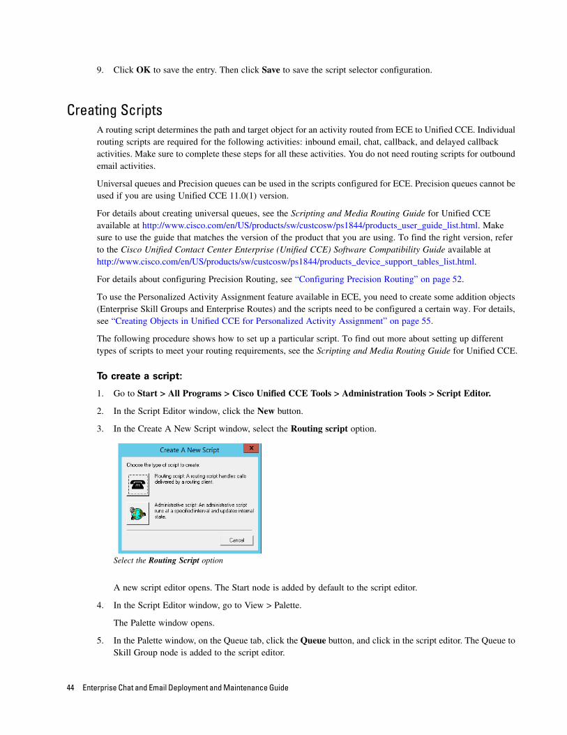
3. In the Create A New Script window, select the Routing script option.
Select the Routing Script option
A new script editor opens. The Start node is added by default to the script editor.
4. In the Script Editor window, go to View > Palette.
The Palette window opens.
5. In the Palette window, on the Queue tab, click the Queue button, and click in the script editor. The Queue to Skill Group node is added to the script editor.
44 Enterprise Chat and Email Deployment and Maintenance Guide
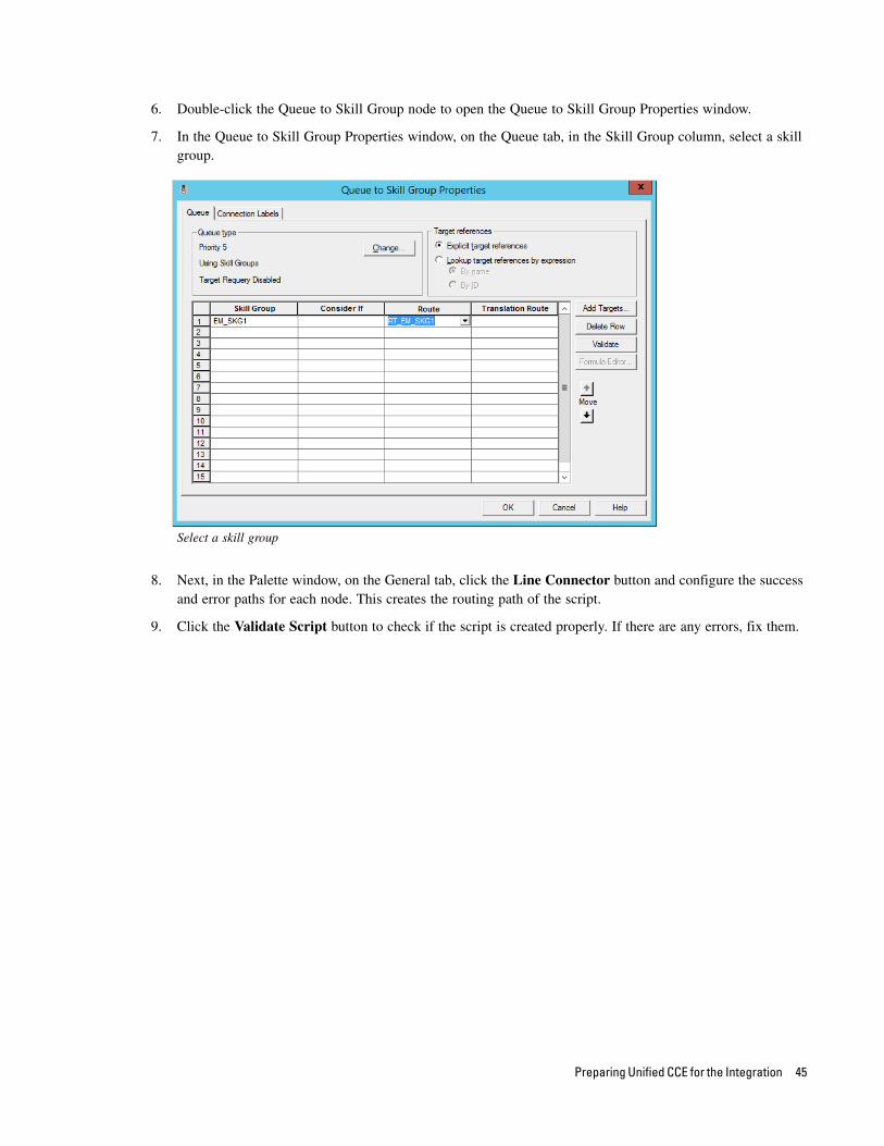
6. Double-click the Queue to Skill Group node to open the Queue to Skill Group Properties window.
7. In the Queue to Skill Group Properties window, on the Queue tab, in the Skill Group column, select a skill group.
Select a skill group
8. Next, in the Palette window, on the General tab, click the Line Connector button and configure the success and error paths for each node. This creates the routing path of the script.
9. Click the Validate Script button to check if the script is created properly. If there are any errors, fix them.
Preparing Unified CCE for the Integration 45
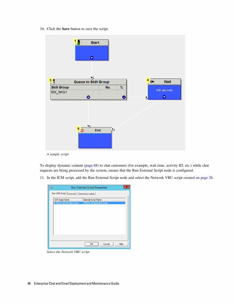
10. Click the Save button to save the script.
A sample script
To display dynamic content (page 68) to chat customers (for example, wait time, activity ID, etc.) while chat requests are being processed by the system, ensure that the Run External Script node is configured.
11. In the ICM script, add the Run External Script node and select the Network VRU script created on page 26.
Select the Network VRU script
46 Enterprise Chat and Email Deployment and Maintenance Guide
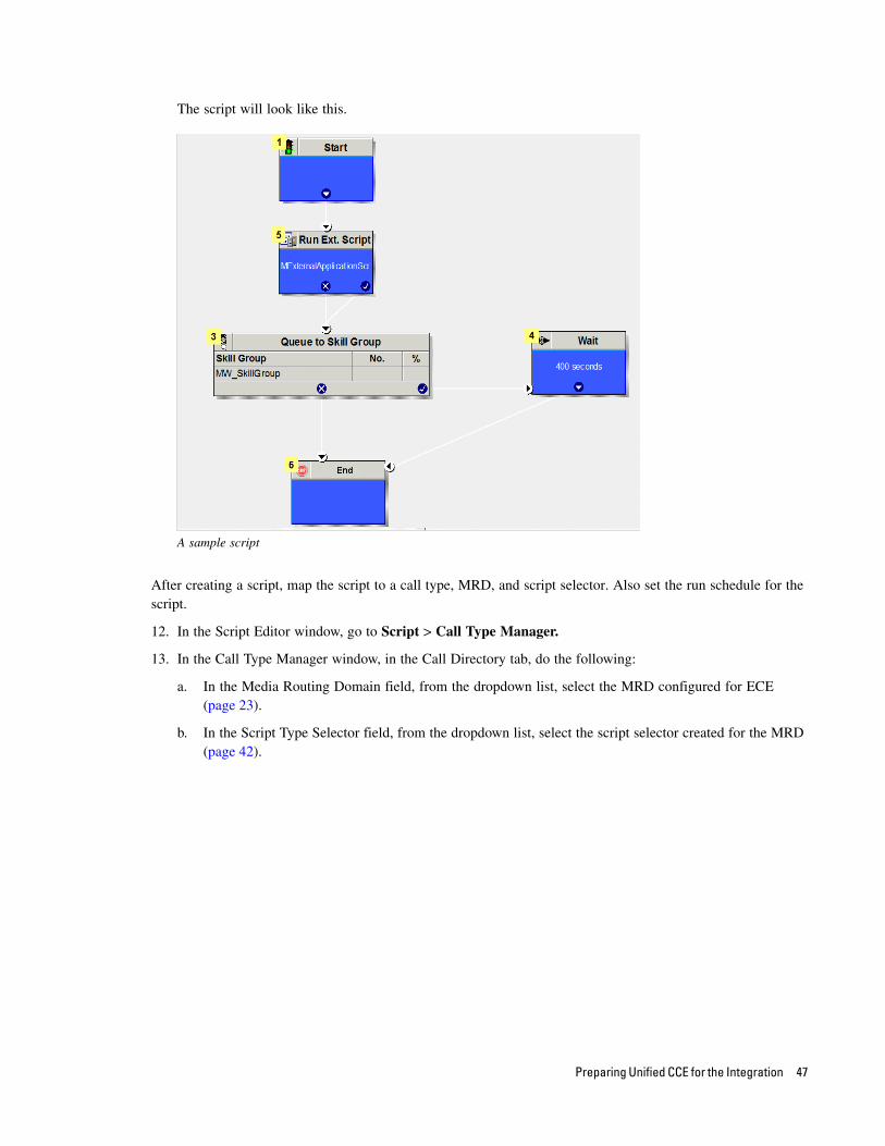
The script will look like this.
A sample script
After creating a script, map the script to a call type, MRD, and script selector. Also set the run schedule for the script.
12. In the Script Editor window, go to Script > Call Type Manager.
13. In the Call Type Manager window, in the Call Directory tab, do the following:
a. In the Media Routing Domain field, from the dropdown list, select the MRD configured for ECE (page 23).
b. In the Script Type Selector field, from the dropdown list, select the script selector created for the MRD (page 42).
Preparing Unified CCE for the Integration 47
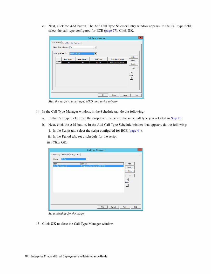
c. Next, click the Add button. The Add Call Type Selector Entry window appears. In the Call type field, select the call type configured for ECE (page 27). Click OK.
Map the script to a call type, MRD, and script selector
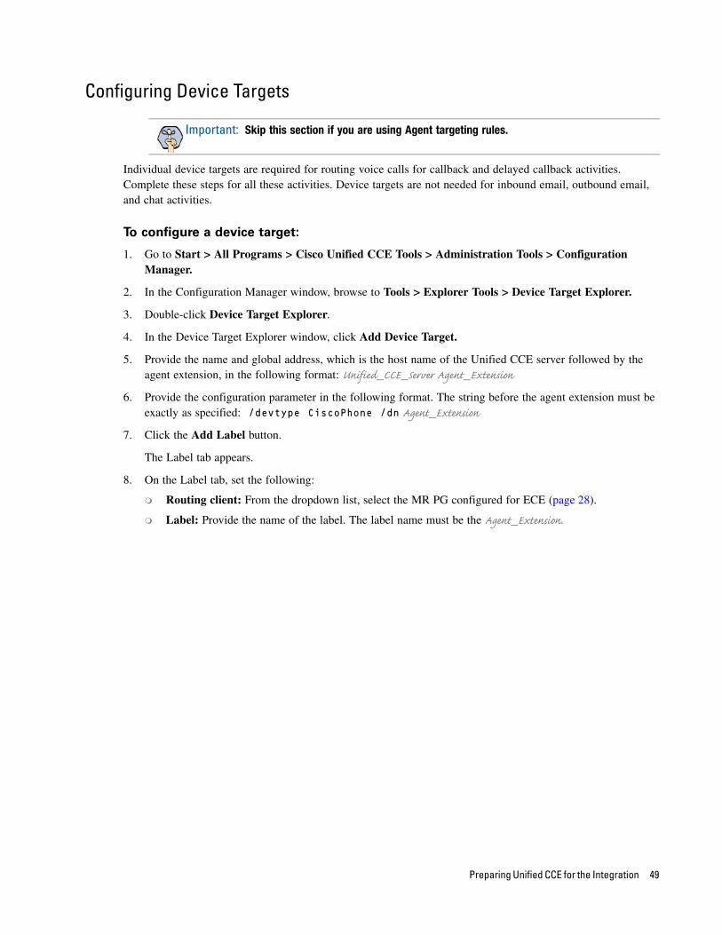
14. In the Call Type Manager window, in the Schedule tab, do the following:
a. In the Call type field, from the dropdown list, select the same call type you selected in Step 13.
b. Next, click the Add button. In the Add Call Type Schedule window that appears, do the following:
i. In the Script tab, select the script configured for ECE (page 44).
ii. In the Period tab, set a schedule for the script.
iii. Click OK.
Set a schedule for the script
15. Click OK to close the Call Type Manager window.
48 Enterprise Chat and Email Deployment and Maintenance Guide
Configuring Device Targets
Individual device targets are required for routing voice calls for callback and delayed callback activities. Complete these steps for all these activities. Device targets are not needed for inbound email, outbound email, and chat activities.
To configure a device target:
1. Go to Start > All Programs > Cisco Unified CCE Tools > Administration Tools > Configuration Manager.
2. In the Configuration Manager window, browse to Tools > Explorer Tools > Device Target Explorer.
3. Double-click Device Target Explorer.
4. In the Device Target Explorer window, click Add Device Target.
5. Provide the name and global address, which is the host name of the Unified CCE server followed by the agent extension, in the following format: Unified_CCE_Server Agent_Extension
6. Provide the configuration parameter in the following format. The string before the agent extension must be exactly as specified: /devtype CiscoPhone /dn Agent_Extension
7. Click the Add Label button.
The Label tab appears.
8. On the Label tab, set the following:
Routing client: From the dropdown list, select the MR PG configured for ECE (page 28).
Label: Provide the name of the label. The label name must be the Agent_Extension.
Important: Skip this section if you are using Agent targeting rules.
Preparing Unified CCE for the Integration 49
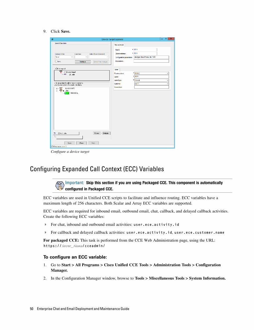
9. Click Save.
Configure a device target
Configuring Expanded Call Context (ECC) Variables
ECC variables are used in Unified CCE scripts to facilitate and influence routing. ECC variables have a maximum length of 256 characters. Both Scalar and Array ECC variables are supported.
ECC variables are required for inbound email, outbound email, chat, callback, and delayed callback activities. Create the following ECC variables:
For chat, inbound and outbound email activities: user.ece.activity.id
For callback and delayed callback activities: user.ece.activity.id, user.ece.customer.name
For packaged CCE: This task is performed from the CCE Web Administration page, using the URL: https://Server_Name/cceadmin/
To configure an ECC variable:
1. Go to Start > All Programs > Cisco Unified CCE Tools > Administration Tools > Configuration Manager.
2. In the Configuration Manager window, browse to Tools > Miscellaneous Tools > System Information.
Important: Skip this section if you are using Packaged CCE. This component is automatically
configured in Packaged CCE.
50 Enterprise Chat and Email Deployment and Maintenance Guide
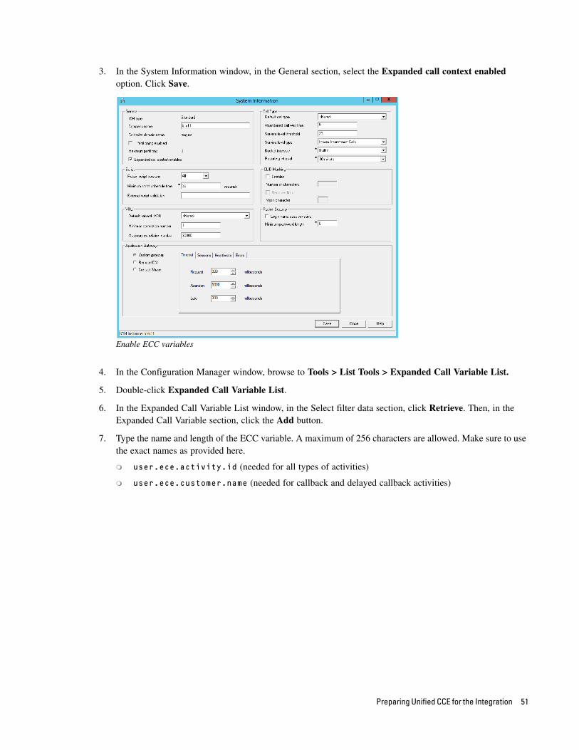
3. In the System Information window, in the General section, select the Expanded call context enabled option. Click Save.
Enable ECC variables
4. In the Configuration Manager window, browse to Tools > List Tools > Expanded Call Variable List.
5. Double-click Expanded Call Variable List.
6. In the Expanded Call Variable List window, in the Select filter data section, click Retrieve. Then, in the Expanded Call Variable section, click the Add button.
7. Type the name and length of the ECC variable. A maximum of 256 characters are allowed. Make sure to use the exact names as provided here.
user.ece.activity.id (needed for all types of activities)
user.ece.customer.name (needed for callback and delayed callback activities)
Preparing Unified CCE for the Integration 51
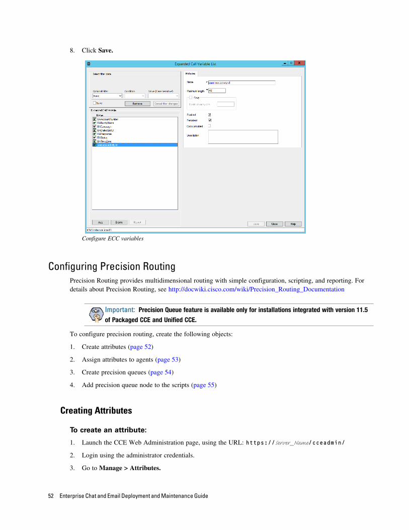
8. Click Save.
Configure ECC variables
Configuring Precision RoutingPrecision Routing provides multidimensional routing with simple configuration, scripting, and reporting. For details about Precision Routing, see http://docwiki.cisco.com/wiki/Precision_Routing_Documentation
To configure precision routing, create the following objects:
1. Create attributes (page 52)
2. Assign attributes to agents (page 53)
3. Create precision queues (page 54)
4. Add precision queue node to the scripts (page 55)
Creating Attributes
To create an attribute:
1. Launch the CCE Web Administration page, using the URL: https://Server_Name/cceadmin/
2. Login using the administrator credentials.
3. Go to Manage > Attributes.
Important: Precision Queue feature is available only for installations integrated with version 11.5
of Packaged CCE and Unified CCE.
52 Enterprise Chat and Email Deployment and Maintenance Guide
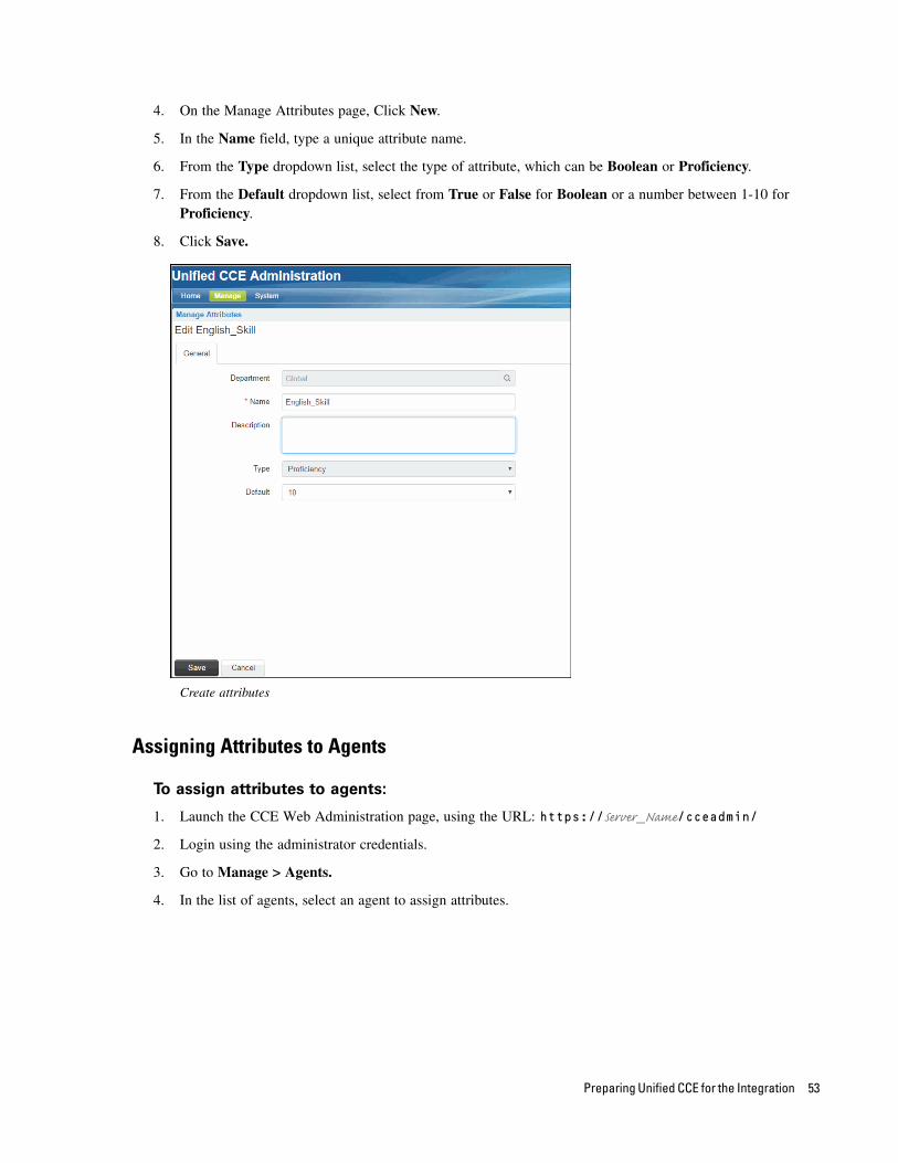
4. On the Manage Attributes page, Click New.
5. In the Name field, type a unique attribute name.
6. From the Type dropdown list, select the type of attribute, which can be Boolean or Proficiency.
7. From the Default dropdown list, select from True or False for Boolean or a number between 1-10 for Proficiency.
8. Click Save.
Create attributes
Assigning Attributes to Agents
To assign attributes to agents:
1. Launch the CCE Web Administration page, using the URL: https://Server_Name/cceadmin/
2. Login using the administrator credentials.
3. Go to Manage > Agents.
4. In the list of agents, select an agent to assign attributes.
Preparing Unified CCE for the Integration 53
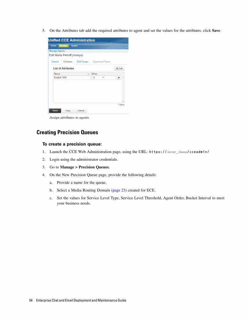
5. On the Attributes tab add the required attributes to agent and set the values for the attributes. click Save.
Assign attributes to agents
Creating Precision Queues
To create a precision queue:
1. Launch the CCE Web Administration page, using the URL: https://Server_Name/cceadmin/
2. Login using the administrator credentials.
3. Go to Manage > Precision Queues.
4. On the New Precision Queue page, provide the following details:
a. Provide a name for the queue.
b. Select a Media Routing Domain (page 23) created for ECE.
c. Set the values for Service Level Type, Service Level Threshold, Agent Order, Bucket Interval to meet your business needs.
54 Enterprise Chat and Email Deployment and Maintenance Guide
d. Create the steps for the precision queue and in the expressions use the attributes created for ECE.
Sample precision queue
Adding Precision Queue Node to the Scripts In the scripts for ECE, add the precision Queue node. For details about doing this task see the Precision
Routing Documentation available at: http://docwiki.cisco.com/wiki/Precision_Routing_Documentation
Creating Objects in Unified CCE for Personalized Activity AssignmentThe personalized activity assignment feature in ECE allows you to assign activities pertaining to a case to the agent who last sent a response for that case. For details about personalized activity assignment settings and how to configure these in ECE, see the Enterprise Chat and Email Administrator’s Guide to Administration Console. Along with these settings in ECE, you need to configure the scripts in Unified CCE in a certain way to support personalized activity assignment.
Create the following objects in Unified CCE:
1. Create Enterprise Skill Groups (page 56).
2. Create an Enterprise Route (page 57).
3. Add the Queue to Agent node in the routing script (page 58).
Important: Personalized activity assignment feature is not available for installations integrated
with Packaged CCE.
Preparing Unified CCE for the Integration 55
Creating Enterprise Skill Group
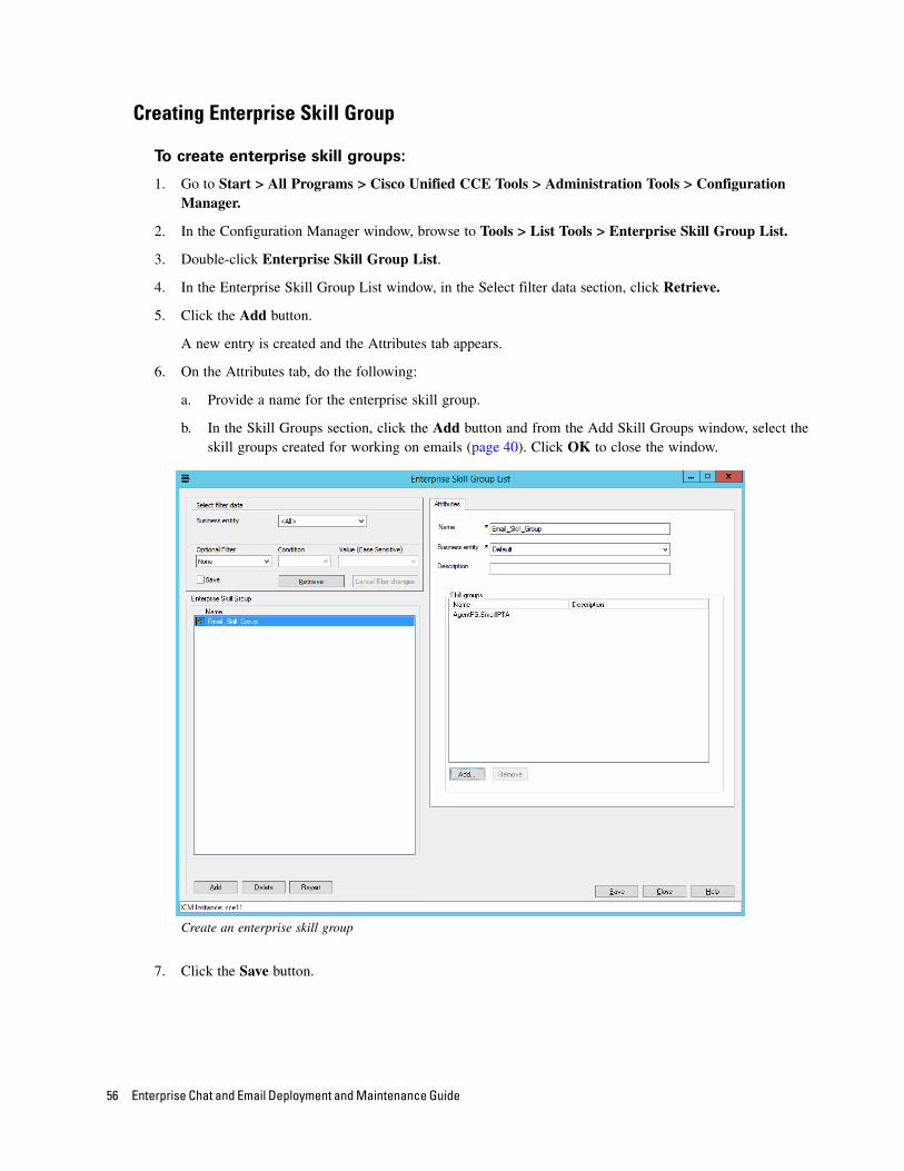
To create enterprise skill groups:
1. Go to Start > All Programs > Cisco Unified CCE Tools > Administration Tools > Configuration Manager.
2. In the Configuration Manager window, browse to Tools > List Tools > Enterprise Skill Group List.
3. Double-click Enterprise Skill Group List.
4. In the Enterprise Skill Group List window, in the Select filter data section, click Retrieve.
5. Click the Add button.
A new entry is created and the Attributes tab appears.
6. On the Attributes tab, do the following:
a. Provide a name for the enterprise skill group.
b. In the Skill Groups section, click the Add button and from the Add Skill Groups window, select the skill groups created for working on emails (page 40). Click OK to close the window.
Create an enterprise skill group
7. Click the Save button.
56 Enterprise Chat and Email Deployment and Maintenance Guide
Creating Enterprise Routes
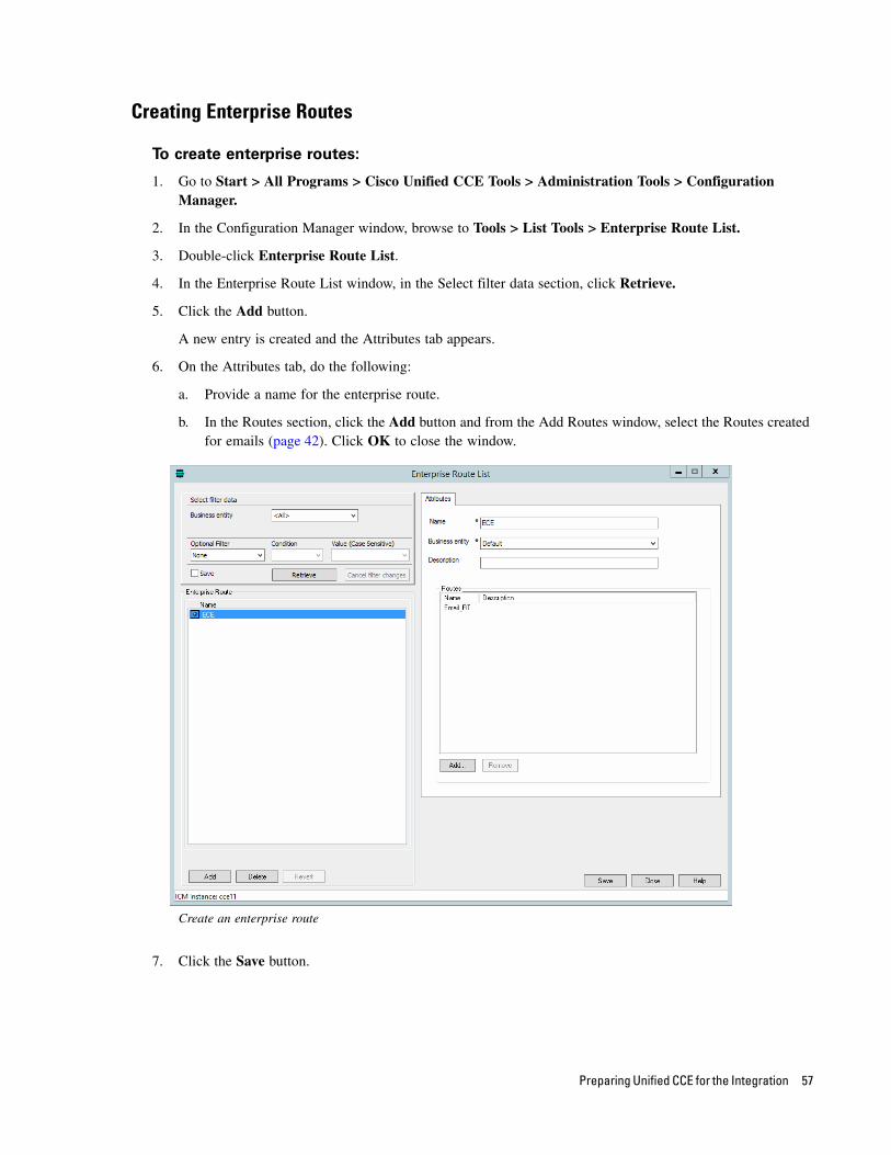
To create enterprise routes:
1. Go to Start > All Programs > Cisco Unified CCE Tools > Administration Tools > Configuration Manager.
2. In the Configuration Manager window, browse to Tools > List Tools > Enterprise Route List.
3. Double-click Enterprise Route List.
4. In the Enterprise Route List window, in the Select filter data section, click Retrieve.
5. Click the Add button.
A new entry is created and the Attributes tab appears.
6. On the Attributes tab, do the following:
a. Provide a name for the enterprise route.
b. In the Routes section, click the Add button and from the Add Routes window, select the Routes created for emails (page 42). Click OK to close the window.
Create an enterprise route
7. Click the Save button.
Preparing Unified CCE for the Integration 57
Adding the Queue to Agent Node in Scripts
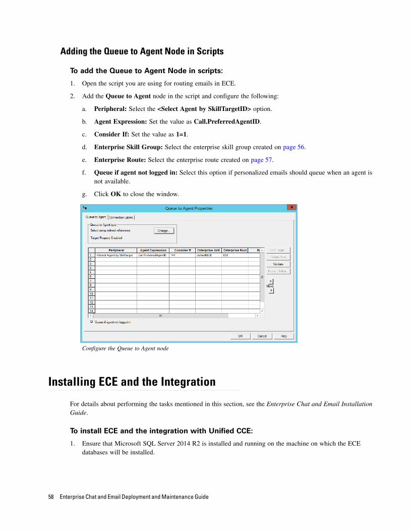
To add the Queue to Agent Node in scripts:
1. Open the script you are using for routing emails in ECE.
2. Add the Queue to Agent node in the script and configure the following:
a. Peripheral: Select the <Select Agent by SkillTargetID> option.
b. Agent Expression: Set the value as Call.PreferredAgentID.
c. Consider If: Set the value as 1=1.
d. Enterprise Skill Group: Select the enterprise skill group created on page 56.
e. Enterprise Route: Select the enterprise route created on page 57.
f. Queue if agent not logged in: Select this option if personalized emails should queue when an agent is not available.
g. Click OK to close the window.
Configure the Queue to Agent node
Installing ECE and the Integration
For details about performing the tasks mentioned in this section, see the Enterprise Chat and Email Installation Guide.
To install ECE and the integration with Unified CCE:
1. Ensure that Microsoft SQL Server 2014 R2 is installed and running on the machine on which the ECE databases will be installed.
58 Enterprise Chat and Email Deployment and Maintenance Guide
2. Install ECE 11.5(1). Refer to the Enterprise Chat and Email Installation Guide for Unified CCE or Enterprise Chat and Email Installation Guide for PCCE for a detailed list of deployment options and installation steps corresponding to each deployment. The document also guides you through the procedure of setting up the integration.
3. From the Windows Services panel, start the Cisco service, and wait for 2–3 minutes before launching the URL to allow all the application services to start.
4. On the administrators desktops, install Oracle JRE 1.8.0 (most recent update). Version 1.8.0_66 is included on the product CD. This is required only to administer workflows from the Administration Console.
5. Configure the browser on user desktops according to the procedures detailed in the Cisco Unified Web and E-Mail Interaction Manager Browser Settings Guide. This is not required for desktops used for accessing the Agent Console.
6. From the ECE Administration Console, import the skill groups, users, and MRDs. For details, see the Enterprise Chat and Email Administrator’s Guide to Administration Console.
Configuring the System for Multiple Agent PGs
Multiple Agent PGs can be used for Unified CCE installations. Note that a unique application path and associated application path members are needed for each Agent PG. The application path is used by the Listener Service to connect and communicate with the Agent PG.
To configure the system for multiple Agent PGs:
1. Create the Agent PGs. For Unified CCE installations, see page 33.
2. In Unified CCE, configure agents (page 39) and skill groups (page 40).
3. From the ECE Administration Console, add the new Agent PG. For each Agent PG that is added, a Listener instance is created in the System Console. Refer to the Enterprise Chat and Email Administrators Guide to Administration Console for details about adding new Agent PGs.
4. Log in to the ECE System Console.
5. Browse to Shared Resource > Services > Unified CCE > Listener. In the List pane, select the Listener process. In the Properties pane, in the Maximum number of instances field increase the value to match the number of Agent PGs you are adding.
6. Browse to Partitions > Partition. In the Properties pane, on the Services tab, set the number of instances for the Listener service to match the number of Agent PGs you are adding.
For details about steps 4-6, see the Enterprise Chat and Email Administrator's Guide to System Console.
Preparing Unified CCE for the Integration 59
Configuring Finesse
Perform these tasks after installing ECE. Cisco Finesse enables the use of custom gadgets for Voice & Multichannel (ECE), facilitating the ECE user interface to be embedded within a gadget to provide contact center agents a unified desktop experience.
Copying Files from ECE Server From the ECE services server, copy the contents of the ECE_Home\Utilities\finesse_gadget folder to a
temporary directory, Temp, on your local machine. In ECE installations integrated with PCCE, this folder is available on the ECE server.
Configuring Finesse FilesPerform these tasks from any local machine.
To configure the ece_config.js file:
1. From the Temp\finesse_gadget\agent folder created on the local machine (page 60) open the ece_config.js file in a text editor.
2. Locate the following text in the file:
var web_server_name = “<Load_Balancer_or_Web_Server_Host_Name>";
3. Replace <Load_Balancer_or_Web_Server_Host_Name> with the host name of the ECE web server. If the deployment uses a load balancer, provide the host name of the load balancer.
Enabling 3rdpartygadget Account and Deploying the GadgetPerform these tasks on the Finesse server.
To enable the 3rdpartygadget account and deploy the Gadget:
1. Using the Finesse Console, login as an administrator and enable the 3rdpartygadget account on the Finesse server.
When you enable the 3rdpartygadget account, a files folder gets created automatically.
2. Create a new folder called ECE under the files folder.
3. Deploy the gadget files from the Temp\finesse_gadget\agent folder and the Temp\finesse_gadget\solve folder on your local machine (page 60) to the Finesse server using a secure FTP client.
Important: Before you begin the configuration, ensure that the Finesse VM and software are
installed and ready for use. Also, ensure that ECE is installed.
60 Enterprise Chat and Email Deployment and Maintenance Guide
Configuring Finesse Settings and LayoutPerform these tasks from any local machine.
To configure the Finesse settings and layout:
1. Launch the URL: http://Finesse_Server_Name/cfadmin. Login as a finesse administrator.
2. Configure the Contact Center CTI Server Settings and Contact Center Enterprise Administration & Data Server Settings.
Configure the settings
3. From Desktops Layout section, configure the layout for the ECE and Solve gadgets. XML contents for the ECE and Solve gadget tabs are available in the following files copied from the ECE server (page 60):
Temp\finesse_gadget\layout\agent.xml
Temp\finesse_gadget\layout\solve.xml
While configuring the gadgets, make sure that the path to the ece.xml file in the <gadget> tag is correct.
Refer the Finesse documentation to see how gadgets are added in Finesse.
Preparing Unified CCE for the Integration 61
Starting Finesse Services
To start the Finesse services:
On the Finesse server, restart Finesse Services by doing the following:
1. Connect to the Finesse Server using a remote client tool. For example, putty.
2. Login using the Finesse Administrator account.
3. Restart Cisco Tomcat service.
utils service restart Cisco Tomcat
4. Restart Cisco Finesse Tomcat service.
utils service restart Cisco Finesse Tomcat
62 Enterprise Chat and Email Deployment and Maintenance Guide
Setting Up Integrated
Objects
Configuring Variables in ECE
Verifying Mapping of Objects in the Administration Console
Setting up Business Objects in the Administration Console
Setting Up Services in the System Console
Setting Up Web Links for Chat and Callback
Configuring Dynamic Messages for Integrated Chats
Related Documentation
This chapter provides an overview of the process of setting up ECE–Unified CCE objects.
Configuring Variables in ECE
While sending new activity requests from a queue to Unified CCE, EAAS sends call variables and ECC variables to Unified CCE as task context. By default, the following activity attributes are sent to Unified CCE as ECC variables.
For inbound and outbound email activities: activity_id
For chat activities: activity_id
For callback and delayed callback activities: activity_id, customer_name
If you need to pass on other attributes of the activity as call variables or ECC variables to Unified CCE, you need to configure them in ECE. These variables can then be used in Unified CCE scripts to configure conditions. For details, see the Unified CCE scripts documentation. If you plan to configure these variables as ECC variables in ECE, you need to first create the ECC variables in Unified CCE. For details, see the Unified CCE documentation.
You can also create variables for custom activity attributes. For details about creating variables, see the “Call Variables” chapter in the Enterprise Chat and Email Administrator's Guide to Routing and Workflows.
Verifying Mapping of Objects in the Administration Console
To verify that Unified CCE objects have been mapped correctly in the ECE
Administration Console:
1. Launch the URL: http://ECE_Web_Server/Default_Partition.
2. Log in as the partition administrator (user name and password that were configured during the installation of ECE). Go to the Administration Console.
3. Under the appropriate department, browse to the User > Users node in the Administration tree, to verify that all users mapping to the administrators, supervisors, and agents, which were selected at the time of importing the objects, are displayed. For details, see the Enterprise Chat and Email Administrator’s Guide to Administration Console.
4. Under the appropriate department, click the User > Groups node in the Administration tree to verify that all user groups mapping to the skill groups, which were selected at the time of importing the objects, are displayed. For details, see the Enterprise Chat and Email Administrator’s Guide to Administration Console.
5. Under the appropriate department, click the Workflow > Queues node in the Administration tree, and verify that all queues mapping to the MRDs, which were selected at the time of importing the objects, are displayed. For details, see the Enterprise Chat and Email Administrator’s Guide to Routing and Workflows.
64 Enterprise Chat and Email Deployment and Maintenance Guide
Setting up Business Objects in the Administration Console
See the following guides for the details of the procedures mentioned in this section:
Enterprise Chat and Email Administrator’s Guide to Routing and Workflows
Enterprise Chat and Email Administrator’s Guide to Email Resources
Enterprise Chat and Email Administrator’s Guide to Chat and Collaboration Resources
To set up ECE business objects in the Administration Console:
1. Launch the URL: http://ECE_Web_Server/Default_Partition.
2. Log in as the partition administrator and go to the Knowledge Base Console.
3. In the Knowledge Base tree, browse to Departments > Department_Name > Content > Shared > Standard > Email. Create an article in each of the sub-nodes to set up one option each for a header, greeting, signature, footer, and auto acknowledgements that can be used in responses to incoming activities in the department.
4. Go to the Administration Console.
5. In the Administration tree, browse to the Administration > Departments > Department_Name > Classifications > Categories node. Create categories.
These categories will be used later in a workflow (see page 65).
6. Now, browse to the Email > Aliases node. Create an alias to serve as the entry point for emails into the system.
7. Then, browse to the Workflow > Workflows > Inbound node to create an inbound workflow for this alias. The workflow will route incoming emails. Add the alias created in Step 6 to the Start node. Add the email queue to the Queue node. Select the auto-acknowledgement KB article created earlier (see page 65) for the Auto-acknowledgement node. Select the categories created in Step 5 for the Classifications node.
8. Browse to the Chat > Entry points node. Create new entry points by assigning the appropriate templates. To route chats and call back activities that enter from this entry point, use an auto-configured queue. Make the entry points active. The configuration steps for entry points are different for different types of activities and routing options.
The activity types for which you need to create entry points are: Chat, Callback, Delayed callback.
9. In the Properties pane, click the Show HTML button. The code used to generate a chat hyperlink to that entry point is displayed. Copy this link code into a Notepad file. Edit the code as explained in the Enterprise Chat and Email Administrator’s Guide to Chat and Collaboration Resources.
Setting Up Integrated Objects 65
Setting Up Services in the System Console
Service processes are managed at the system level as shared resources across partitions. Service instances are managed within partitions.
See Enterprise Chat and Email Administrator's Guide to System Console for the details of the procedures mentioned in this section.
This section helps you set up processes and instances for the following services:
Retriever: Gets incoming emails from configured aliases and parses them.
Workflow Cache: Maintains the files that store information about objects used in workflows.
Workflow Engine: Applies workflows on emails to automate their routing and handling.
Dispatcher: Sends outgoing emails out of the system.
External Agent Assignment Service (EAAS): Identifies new activities that arrive into an external assignment queue, and routes requests for each of these activities to Unified CCE for routing to take place through Unified CCE.
Listener: Assigns activities to target agents or user groups (skill groups) identified by Unified CCE, and reports the status of both the activity and the agent to Unified CCE throughout the life cycle of the given activity.
Context Service: This service synchronizes activities and customer’s information between the Cisco ECE and Cisco Context Service. This service only applies to systems using Cisco Context Service. For details on Context Service availability, visit https://help.webex.com/community/context-service.
To set up ECE services in the System Console:
See Enterprise Chat and Email Administrator's Guide to System Console for the details of the procedures mentioned in this section.
1. Open a new browser window, and launch the URL: http://ECE_Web_Server/Context_Root. Log in as the system administrator (user name and password that were configured during the installation of ECE). Go to the System Console.
2. Browse to the Partitions > Partition > Services > Email > Retriever node. Click the Retriever instance to use in the partition, and select the email alias that you had created earlier in the Administration Console (see page 65).
3. Restart the Retriever process and instance based on the notification message that appears. Browse to Shared Resource > Services > Retriever, and stop and start the Retriever process for the system. Also ensure that the start type for the service process is set to automatic.
4. Navigate back to the Partitions > Partition > Services > Retriever node. Ensure that the start type for the service instance is set to automatic. Stop and start the Retriever instance.
5. Browse to Shared Resource > Services > Workflow > Workflow Cache and verify that the Workflow Cache process is running. If the process is in a stopped state, start the process by clicking the Run button. Also ensure that the start type for the service process is set to automatic.
6. Browse to Partitions > Partition > Services > Workflow > Workflow Cache and ensure that the start type for the service instance is set to automatic. Start the Workflow Cache instance.
66 Enterprise Chat and Email Deployment and Maintenance Guide
7. Browse to Shared Resource > Services > Workflow > Workflow Engine and verify that the Workflow Engine process is running. If the process is in a stopped state, start the process by clicking the Run button. Also ensure that the start type for the service process is set to automatic.
8. Browse to Partitions > Partition > Services > Workflow > Workflow Engine and ensure that the start type for the service instance is set to automatic. Start the Workflow Engine instance.
9. Browse to Shared Resource > Services > Email > Dispatcher and verify that the Dispatcher process is running. If the process is in a stopped state, start the process by clicking the Run button. Also ensure that the start type for the service process is set to automatic.
10. Browse to Partitions > Partition > Services > Email > Dispatcher and ensure that the start type for the service instance is set to automatic. Start the Dispatcher instance.
11. Browse to Shared Resource > Services > Unified CCE > Listener and verify that the Listener process is running. If the process is in a stopped state, start the process by clicking the Run button. Also ensure that the start type for the service process is set to automatic.
12. Browse to Partitions > Partition > Services > Unified CCE > Listener. Verify that the Listener instance for the Agent PG is automatically created. Also ensure that the start type for the instance is set to automatic. Then start the Listener instance.
13. Browse to Shared Resource > Services > Unified CCE > EAAS and verify that the EAAS process is running. If the process is in a stopped state, start the process by clicking the Run button. Also ensure that the start type for the service process is set to automatic.
14. Browse to Partitions > Partition > Services > Unified CCE > EAAS. Configure the EAAS instance by providing the MR Connection port number you provided while creating the MR PIM (page 28). Also ensure that the start type for the instance is set to automatic. Start the EAAS instance.
15. Browse to Shared Resource > Services > Unified CCE > Context Service and verify that the Context Service process is running. If the process is in a stopped state, start the process by clicking the Run button. Also ensure that the start type for the service process is set to automatic. If the ECE services server or ECE Server (in deployments integrated with Packaged CCE) is behind a firewall and does not have direct access to the internet, the Proxy Server URL should be provided so that the server can connect to the Cisco Context Service. Format of the URL is: http://ProxyServerName:Port or https://ProxyServerName:Port
16. Browse to Partitions > Partition > Services > Unified CCE > Context Service. Ensure that the start type for the instance is set to automatic. Then start the Context Service instance.
Setting Up Web Links for Chat and Callback
To create a chat and collaboration link on your web site:
Open the code view of the host web page and add the edited link code (see page 65) from the entry point properties at the appropriate point. You may need to ask your web master to perform this task.
ECE is now ready for use. To verify, log in as an agent, supervisor, or administrator and perform basic tasks.
Setting Up Integrated Objects 67
Configuring Dynamic Messages for Integrated Chats
Dynamic Run Application Script Request (DRASR) allows you to display wait messages with dynamic text (such as expected wait time) to customers while chat and call requests are being processed by the ECE and Unified CCE integrated systems. You can use ECC variables and call variables to display the dynamic content. For details about configuring DRASR, refer the Enterprise Chat and Email Administrator’s Guide to Chat and Collaboration Resources.
Related Documentation
Refer to the following ECE User’s Guides (for the Unified CCE integration) for more information about configuring and using ECE.
Enterprise Chat and Email Administrator’s Guide to Administration Console helps administrators set up and manage business objects.
Enterprise Chat and Email Administrator’s Guide to Chat and Collaboration Resources helps administrators set up templates and entry points.
Enterprise Chat and Email Administrator’s Guide to Email Resources helps administrators set up aliases, blocked addresses, delivery exceptions, and blocked file extensions.
Enterprise Chat and Email Administrator’s Guide to Routing and Workflows helps administrators set up service levels, queues, and workflows.
Enterprise Chat and Email Administrator’s Guide to System Console helps system administrators set up and manage services, loggers, and system monitors.
Enterprise Chat and Email Administrator’s Guide to Tools Console helps administrators add custom attributes.
Enterprise Chat and Email Supervisor’s Guide helps supervisors set up and use agent and queue monitors.
Enterprise Chat and Email Administrator’s Guide to Reports Console helps managers and supervisors to set up and run reports to analyze various aspects of the system.
Enterprise Chat and Email Agent’s Guide helps agents handle email and chat interactions.
68 Enterprise Chat and Email Deployment and Maintenance Guide
Managing and Maintaining Servers
Best Practices for Configuring Servers
Routine Maintenance Tasks
Performance Tuning Considerations
This chapter will assist you in understanding how to configure and maintain the ECE servers.
Best Practices for Configuring Servers
For All ServersThis section describes the best practices for configuring all the ECE servers. For database server, there are some additional best practices that are listed in the section “Additional Best Practices for Database Servers” on page 70.
Configuring Anti-virus Protection To ensure that virus and malware scanning software on the servers do not interfere with the performance of
the application, certain folders and files must be excluded from continuous virus scanning. Since no files are downloaded to these locations from the internet, it is safe to exclude these directories from virus scanning. For details about doing this task, see the “Post-Installation Tasks” chapter in the Enterprise Chat and Email Installation Guide.
Additional Best Practices for Database ServersIn addition to the best practices that apply to all the ECE servers, there are some special best practices for the database server that are described in this section.
Installation and Settings Check the values set for fill factor and max degree of parallelism. To reduce I/O (disk input
output) on SQL server, the fill factor should be set to 80%. This ensures that 20% free space is available in the data pages of indexes, and it reduces page splitting. The max degree of parallelism should be set to the number of physical processors. For example, if there are two processors, set max degree of parallelism to 2; and if there are five processors, set max degree of parallelism to 5.
a. On the database server, run the following stored procedure.
EXEC sp_configure 'show advanced option', '1'
Reconfigure
exec sp_configure
b. If the fill factor and max degree of parallelism is not configured correctly, run the following stored procedure on the database.
exec sp_configure 'fill factor (%)', 80
exec sp_configure 'max degree of parallelism', Number_Of_Physical_Processors
reconfigure with override
70 Enterprise Chat and Email Deployment and Maintenance Guide
In order to ensure that select queries from the application execute optimally, and with the least possibility of encountering SQL deadlocks with other modification queries, it is required that the Read commit snapshot property is enabled for the Active database. To enable this property:
a. Ensure that ECE is stopped completely. All distributed components such as the services server, all application servers and messaging server should be stopped. For these commands to succeed, there must not be any database connections to the ActiveDB.
b. Verify the current value of the Read commit snapshot property for the Active database by running the following select query:
select name,snapshot_isolation_state_desc,is_read_committed_snapshot_on from sys.databases
c. If the Read commit snapshot property is disabled, run the following query to enable it:
alter database Active_Database_Name set single_user with rollback immediate;
alter database Active_Database_Name set read_committed_snapshot on;
alter database Active_Database_Name set multi_user;
d. Verify that the Read commit snapshot property has been enabled successfully by running the following query.
select name,snapshot_isolation_state_desc,is_read_committed_snapshot_on from sys.databases
Temp Database
Set the temp database properties as follows:
Data file size should be set to 1.5 GB. Autogrowth should be set to 1 GB.
Transaction log file size should be set to 1 GB. Autogrowth should be set to 1 GB.
Number of data files for temp database should be 4 (it is same as number of cores on the VM but not exceeding 8). All files should be around same size with autogrowth on.
Master Database
Set the master database properties as follows:
Data file size should be set to minimum 50 MB. Autogrowth should be set to 50 MB.
Transaction log file size should be set to 50 MB. Autogrowth should be set to 50 MB.
Active Database
While installing the application, ensure that data and log files of the active database reside on a disk volume with a good amount of free disk space. To calculate the required free disk space, see the Enterprise Chat and Email Design Guide.
Set the active database properties as follows:
Data file size should be set to 20 GB. Autogrowth should be set to 1 GB.
Transaction log file size should be set to 2 GB. Autogrowth should be set to 1 GB.
Managing and Maintaining Servers 71
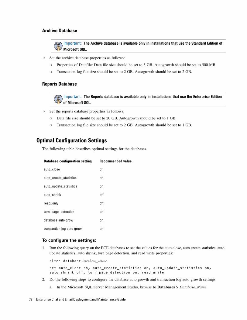
Archive Database
Set the archive database properties as follows:
Properties of Datafile: Data file size should be set to 5 GB. Autogrowth should be set to 500 MB.
Transaction log file size should be set to 2 GB. Autogrowth should be set to 2 GB.
Reports Database
Set the reports database properties as follows:
Data file size should be set to 20 GB. Autogrowth should be set to 1 GB.
Transaction log file size should be set to 2 GB. Autogrowth should be set to 1 GB.
Optimal Configuration SettingsThe following table describes optimal settings for the databases.
To configure the settings:
1. Run the following query on the ECE databases to set the values for the auto close, auto create statistics, auto update statistics, auto shrink, torn page detection, and read write properties:
alter database Database_Name
set auto_close on, auto_create_statistics on, auto_update_statistics on, auto_shrink off, torn_page_detection on, read_write
2. Do the following steps to configure the database auto growth and transaction log auto growth settings.
a. In the Microsoft SQL Server Management Studio, browse to Databases > Database_Name.
Important: The Archive database is available only in installations that use the Standard Edition of
Microsoft SQL.
Important: The Reports database is available only in installations that use the Enterprise Edition
of Microsoft SQL.
Database configuration setting Recommended value
auto_close off
auto_create_statistics on
auto_update_statistics on
auto_shrink off
read_only off
torn_page_detection on
database auto grow on
transaction log auto grow on
72 Enterprise Chat and Email Deployment and Maintenance Guide
b. Right-click the database name and from the menu, select Properties. In the Database Properties window select Files, and in the Database files section, in the Autogrowth field click the Assistance button.
c. In the Change Autogrowth for File_Name window, select the Enable Autogrowth setting and configure the autogrowth settings.
Enable the autogrowth setting
Routine Maintenance Tasks
For All ServersThis section describes the routine maintenance tasks for the ECE servers. For database server, there are some additional tasks that are listed in the section “Additional Tasks for Database Servers” on page 74.
Monitoring Disk Space Monitor and free space on disk volumes periodically by deleting the unnecessary files. Installation
programs, application logs, user profiles, Dr. Watson logs, temp files are known to occupy the space unnecessarily. It is recommended that such files are deleted on a regular basis. However, if it is not possible to free disk space further because of the size of the data, the administrator should plan archiving of old data, or migration of the system to a larger capacity server.
Applying Microsoft Security Patches Apply the security patches released by Microsoft to plug vulnerabilities in the operating system and various
programs.
Creating Backup Copies Back up the Cisco_Home folder on the file, application, messaging, and services servers regularly. Exclude
the log folder under Cisco_Home from the backup. The process of backing up the database is different. For details, see the section “Additional Tasks for Database Servers” on page 74.
Managing and Maintaining Servers 73
Additional Tasks for Database ServersIn addition to the routine maintenance tasks that apply to all the ECE servers, there are some special tasks for the database server that are described in this section.
Performing Disk Defragmentation Weekly defragmentation is recommended. Note that it requires downtime.
Monitoring Summarization Job RunsOn a weekly basis, verify that all the summarization jobs enabled for ECE are running successfully at the scheduled times.
To view the summarization job run details:
1. In the Microsoft SQL Server Management Studio, browse to SQL Server Agent > Jobs.
2. In the jobs list, locate the job populatesmy_Database_Name. Where Database_Name is the name of the active database (in SQL Server Standard installations), or the reports database (in SQL Server Enterprise installations).
3. Right-click the populatesmy_Database_Name job and from the menu select View History.
4. In the Log File Viewer window, browse to Job History and check the following:
In the Date column, the date and time should not be very old as jobs run every 30 minutes.
For all successfully run jobs, the date column will show a green check mark.
74 Enterprise Chat and Email Deployment and Maintenance Guide
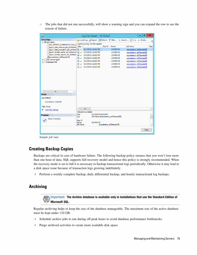
The jobs that did not run successfully, will show a warning sign and you can expand the row to see the reason of failure.
Sample job runs
Creating Backup CopiesBackups are critical in case of hardware failure. The following backup policy ensures that you won’t lose more than one hour of data. SQL supports full recovery model and hence this policy is strongly recommended. When the recovery mode is set to full it is necessary to backup transactional logs periodically. Otherwise it may lead to a disk space issue because of transaction logs growing indefinitely.
Perform a weekly complete backup, daily differential backup, and hourly transactional log backups.
Archiving
Regular archiving helps to keep the size of the database manageable. The maximum size of the active database must be kept under 110 GB.
Schedule archive jobs to run during off-peak hours to avoid database performance bottlenecks.
Purge archived activities to create more available disk space.
Important: The Archive database is available only in installations that use the Standard Edition of
Microsoft SQL.
Managing and Maintaining Servers 75
Performance Tuning Considerations
One of the first steps towards tuning an application is to determine evolving requirements, which is not easy as requirements are likely to vary across different types of users. Administrators, typically, want the system to be easily configurable for various user loads, security needs, and application uptime. Business managers tend to care about issues such as security considerations for critical data that is passed between various components within the application, response times, reliability, availability, and scalability. For agents, response time is the most important factor that defines a finely tuned system.
Enterprise Chat and Email Design Guide helps to plan the configuration when you first set it up. In this section, we provide a quick overview of some of the factors that should be considered as the system grows.
Peak Concurrent UsageThe application will need to be tuned if there is a need to meet specific concurrent usage requirements. Concurrent usage includes usage by email and chat agents as well as chat sessions. The general guideline is that the greater the number of concurrent users, the likelier it is for the system to be stressed resulting in longer response times.
Email VolumeThe email volume that the application handles determines the amount of disk space used by the database, size of active and master databases, and the capacity of the database engine to provide optimal response times to data requests. Active usage of email attachments and Knowledge Base (KB) articles also affect disk space requirements.
Security RequirementsOften security requirements dictate that the application data should be accessed in a secure way. For this reason secure sockets layer (SSL) mode of access to information is set up. Likewise, sharing and access to critical information such as customer data require that data is stored and retrieved in a secure way by extra access control and beyond.
Additional security requirements do lead to some delay in response times for users accessing the application. This should be clearly understood by administrators setting up SSL mode of access on web servers or trying to access information stored on remote and highly secure resources like remotely mounted file systems or disks.
See Enterprise Chat and Email Installation Guide for information about how to set up the SSL mode of communication on the web server.
76 Enterprise Chat and Email Deployment and Maintenance Guide