ensc 494 project report polymumps flexure design · ensc 494 project report polymumps flexure...
TRANSCRIPT

ENSC 494 Project Report
PolyMUMPs Flexure Design
Garet Kim Jessica McAlister
Lydia Tse
August 8, 2003
Abstract .............................................................................................................................. iii 1. Introduction.................................................................................................................... 1
1.1 Background on Flexure Hinges .......................................................................... 1 1.2 Advantages of Flexure Hinges............................................................................ 1 1.3 Limitations of Flexure Hinges ............................................................................ 2 1.4 PolyMUMPs Technology Background............................................................... 2 1.5 Project Goal ........................................................................................................ 3
2. Design Evolution ........................................................................................................... 3 2.1 Original Design................................................................................................... 3 2.2 Intermediate Design ............................................................................................ 4 2.3 Final Design ........................................................................................................ 6
3. Design Implementation.................................................................................................. 7 3.1 List of Components............................................................................................. 7 3.2 Design Variations................................................................................................ 7 3.3 Pulling Mechanisms............................................................................................ 8 3.4 Motion Predictions............................................................................................ 10
3.4.1 Basic Flexures........................................................................................... 10 3.4.2 Cascaded Flexures .................................................................................... 11 3.4.3 Buckling Systems...................................................................................... 12
3.5 Design Issues .................................................................................................... 14 4. Future Research ........................................................................................................... 15 5. Conclusion ................................................................................................................... 15 6. References.................................................................................................................... 16 Appendix A: List of Components ..................................................................................... 17 Appendix B: List of Variations........................................................................................ 19
ii
Abstract Most mechanical designs rely on rotation of some sort in order to function. Many of these designs make use of pin-joints to satisfy rotational requirements. The drawback of pin-joints is that backlash can affect the performance of the system. When designing on a micro scale, the backlash problem becomes a more significant issue. Flexure hinges are a relatively new strategy for providing zero backlash rotation. Flexure hinges on a micro scale are not yet well understood and this paper outlines a project designed to further the research in micro scale flexure hinges. This paper also outlines designs that use the unfavorable buckling phenomenon in a productive manner. All designs were formed using a PolyMUMPs process.
iii
1. Introduction
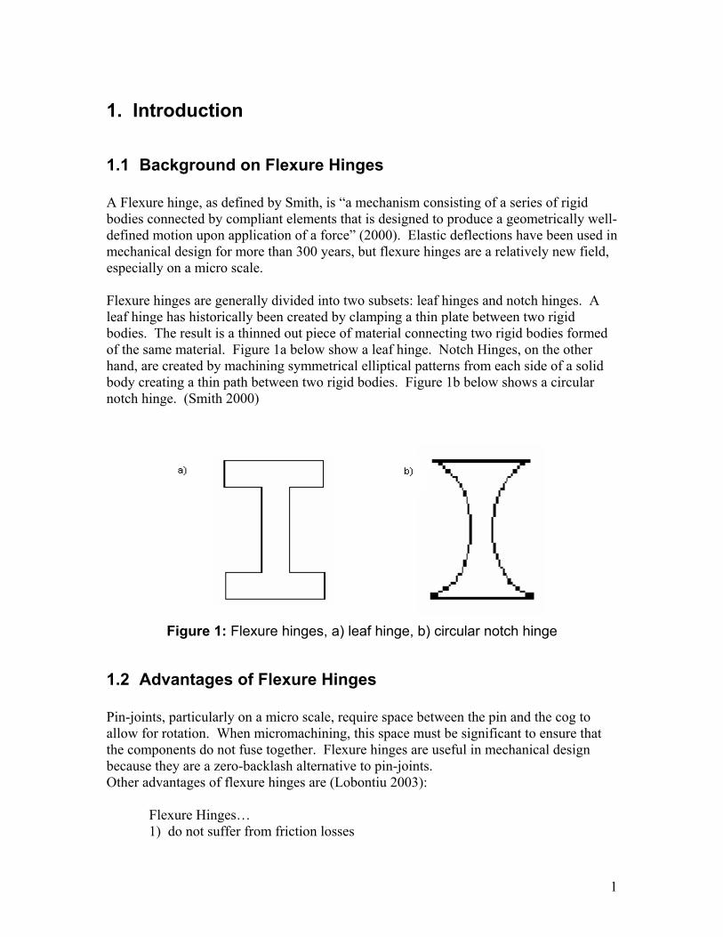
1.1 Background on Flexure Hinges A Flexure hinge, as defined by Smith, is “a mechanism consisting of a series of rigid bodies connected by compliant elements that is designed to produce a geometrically well-defined motion upon application of a force” (2000). Elastic deflections have been used in mechanical design for more than 300 years, but flexure hinges are a relatively new field, especially on a micro scale. Flexure hinges are generally divided into two subsets: leaf hinges and notch hinges. A leaf hinge has historically been created by clamping a thin plate between two rigid bodies. The result is a thinned out piece of material connecting two rigid bodies formed of the same material. Figure 1a below show a leaf hinge. Notch Hinges, on the other hand, are created by machining symmetrical elliptical patterns from each side of a solid body creating a thin path between two rigid bodies. Figure 1b below shows a circular notch hinge. (Smith 2000)
Figure 1: Flexure hinges, a) leaf hinge, b) circular notch hinge
1.2 Advantages of Flexure Hinges Pin-joints, particularly on a micro scale, require space between the pin and the cog to allow for rotation. When micromachining, this space must be significant to ensure that the components do not fuse together. Flexure hinges are useful in mechanical design because they are a zero-backlash alternative to pin-joints. Other advantages of flexure hinges are (Lobontiu 2003): Flexure Hinges… 1) do not suffer from friction losses
1
2) do not require lubrication 3) do not suffer from hysteresis 4) are compact 5) are capable of functioning in small-scale applications 6) are easy to fabricate 7) require little to no maintenance
1.3 Limitations of Flexure Hinges Flexure hinges are not exempt from drawbacks. Some of the limitations include (Lobontiu 2003): Flexure Hinges: 1) provide low level of rotation 2) do not provide pure rotation (deformation of a flexure is complex) 3) do not have a fixed rotation centre 4) are usually sensitive to temperature variations 5) cannot tolerate large loads
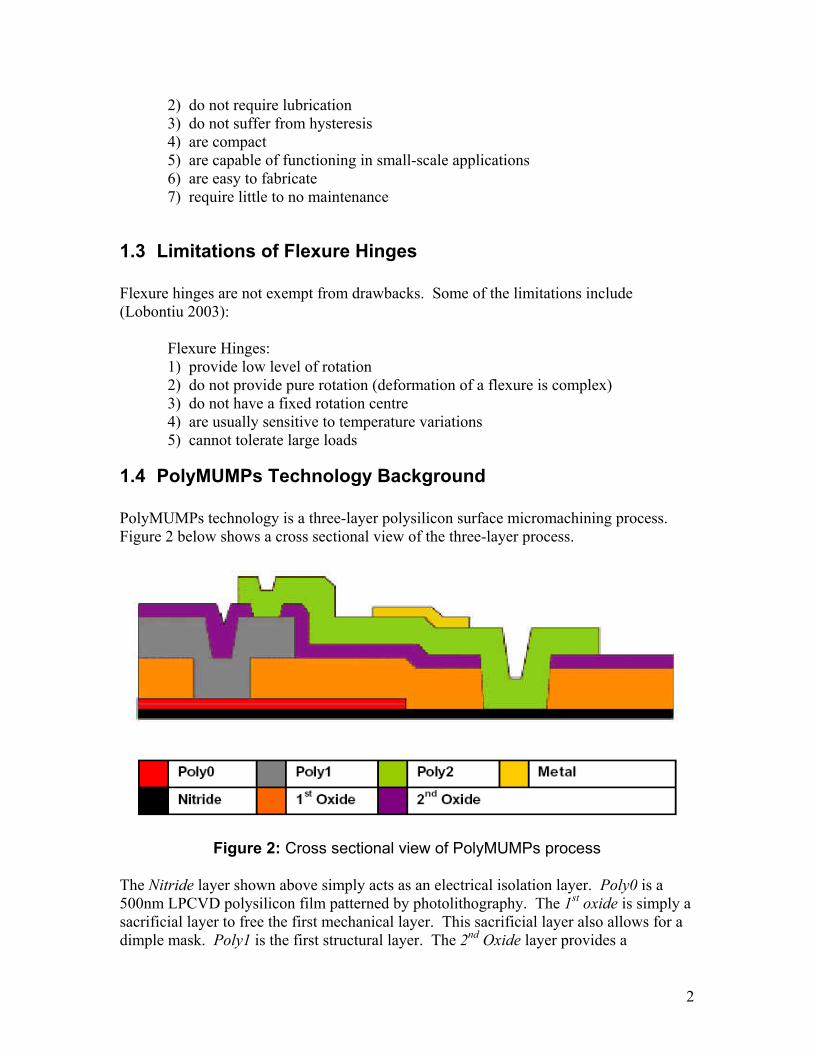
1.4 PolyMUMPs Technology Background PolyMUMPs technology is a three-layer polysilicon surface micromachining process. Figure 2 below shows a cross sectional view of the three-layer process.
Figure 2: Cross sectional view of PolyMUMPs process
The Nitride layer shown above simply acts as an electrical isolation layer. Poly0 is a 500nm LPCVD polysilicon film patterned by photolithography. The 1st oxide is simply a sacrificial layer to free the first mechanical layer. This sacrificial layer also allows for a dimple mask. Poly1 is the first structural layer. The 2nd Oxide layer provides a
2
mechanical and electrical connection between Poly1 and Poly2. Poly2 is the second structural layer. Finally the metal layer allows for probing, bonding, electrical routing and mirrored surfaces. (Koester 2003)
1.5 Project Goal Our project objectives is as follows:
A flexure-spring based extender stage is to be designed. Instead of using hinges or pin-joints, a folding/extending stage is to be designed using flexure joints. By combining this flexure folding system with a linear stepper motor, a MEMS zero-backlash slider can be created.
The limitations of the PolyMUMPs technology forced us to modify the project objectives throughout the course of the semester. In the end, we aimed to create a test bench type environment to aid in the collection of data regarding flexure hinges of varying dimensions. We hope that this initial research into flexure hinges will lead to more meaningful designs in future applications.
2. Design Evolution
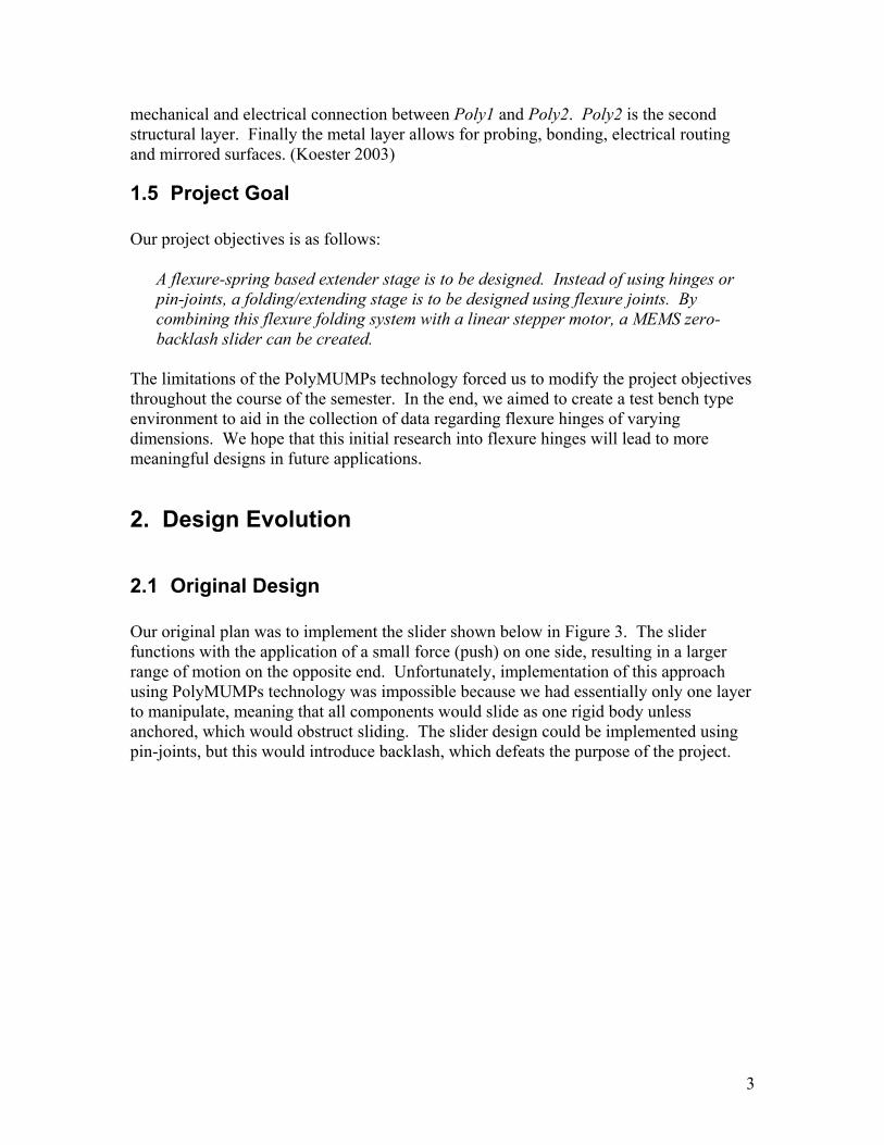
2.1 Original Design Our original plan was to implement the slider shown below in Figure 3. The slider functions with the application of a small force (push) on one side, resulting in a larger range of motion on the opposite end. Unfortunately, implementation of this approach using PolyMUMPs technology was impossible because we had essentially only one layer to manipulate, meaning that all components would slide as one rigid body unless anchored, which would obstruct sliding. The slider design could be implemented using pin-joints, but this would introduce backlash, which defeats the purpose of the project.
3
Small Push
Big Slide
Figure 3: Slider Design Approach
2.2 Intermediate Design
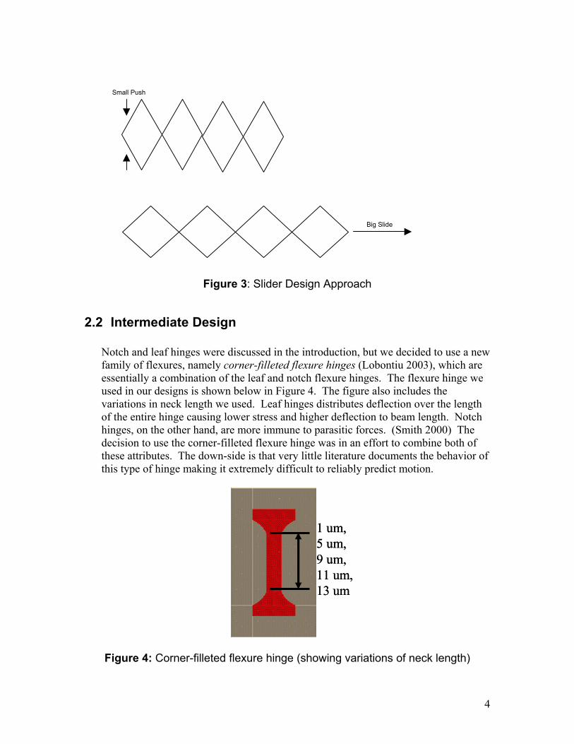
Notch and leaf hinges were discussed in the introduction, but we decided to use a new family of flexures, namely corner-filleted flexure hinges (Lobontiu 2003), which are essentially a combination of the leaf and notch flexure hinges. The flexure hinge we used in our designs is shown below in Figure 4. The figure also includes the variations in neck length we used. Leaf hinges distributes deflection over the length of the entire hinge causing lower stress and higher deflection to beam length. Notch hinges, on the other hand, are more immune to parasitic forces. (Smith 2000) The decision to use the corner-filleted flexure hinge was in an effort to combine both of these attributes. The down-side is that very little literature documents the behavior of this type of hinge making it extremely difficult to reliably predict motion.
1 um,5 um,9 um,11 um,13 um
1 um,5 um,9 um,11 um,13 um
Figure 4: Corner-filleted flexure hinge (showing variations of neck length)
4
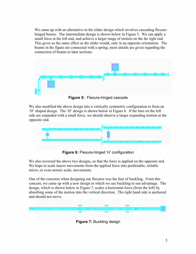
We came up with an alternative to the slider design which involves cascading flexure-hinged beams. The intermediate design is shown below in Figure 5. We can apply a small force at the left end, and achieve a larger range of motion on the far right end. This gives us the same effect as the slider would, only in an opposite orientation. The beams in the figure are connected with a spring; more details are given regarding the connection of beams in later sections.
Figure 5: Flexure-hinged cascade
We also modified the above design into a vertically symmetric configuration to form an ‘H’ shaped design. The ‘H’ design is shown below in Figure 6. If the bars on the left side are expanded with a small force, we should observe a larger expanding motion at the opposite end.
Figure 6: Flexure-hinged ‘H’ configuration
We also reversed the above two designs, so that the force is applied on the opposite end. We hope to scale macro movements from the applied force into predictable, reliable micro, or even atomic scale, movements. One of the concerns when designing our flexures was the fear of buckling. From this concern, we came up with a new design in which we use buckling to our advantage. The design, which is shown below in Figure 7, scales a horizontal force (from the left) by absorbing some of the motion into the vertical direction. The right hand side is anchored and should not move.
Figure 7: Buckling design
5
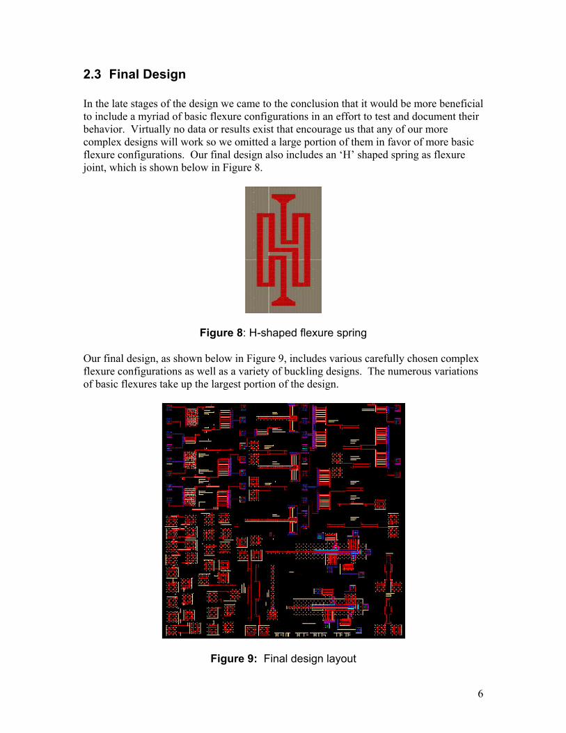
2.3 Final Design In the late stages of the design we came to the conclusion that it would be more beneficial to include a myriad of basic flexure configurations in an effort to test and document their behavior. Virtually no data or results exist that encourage us that any of our more complex designs will work so we omitted a large portion of them in favor of more basic flexure configurations. Our final design also includes an ‘H’ shaped spring as flexure joint, which is shown below in Figure 8.
Figure 8: H-shaped flexure spring Our final design, as shown below in Figure 9, includes various carefully chosen complex flexure configurations as well as a variety of buckling designs. The numerous variations of basic flexures take up the largest portion of the design.
Figure 9: Final design layout
6
3. Design Implementation
3.1 List of Components Please refer to Appendix A for a list of components.
3.2 Design Variations Although one can predict the motion of the mechanical design up to certain expectation through mathematical proof and computer-aided simulations, it’s one of goals of this project to identify factors that affect movement of flexures or buckling designs. Such factors can be difference in dimensions of the design or augmentation to the design. In this project, we varied design parameters such as length and width, neck shape, ratio in flexure, number of cascades, and/or joint springs. Hence, our design fulfills the role as a test bench for new concepts, micro flexures and thin plate buckling designs. A complete variation chart and a list of components are available in the appendix. In order to watch the effect of a particular design parameter, we varied that parameter and kept all other conditions constant. For instance, to observe the effect of different widths, we had two identical designs with different width, as shown below.
Table 1: Different Width in Buckling Designs
Name Length WidthBuckling_598_thin_good 598 11
Buckling_598_good 598 16 Another example is shown as following:
Table 2: Different Springs in H designs
Name Length Width Neck Ratio # Cascades Spring
h2x2_10x1_sn_s3 330 10 11 X 3 10:01 4 s3
h2x2_10x1_sn_s2 330 10 11 X 3 10:01 4 s2 For a more detailed list of design variations please refer to Appendix B.
7
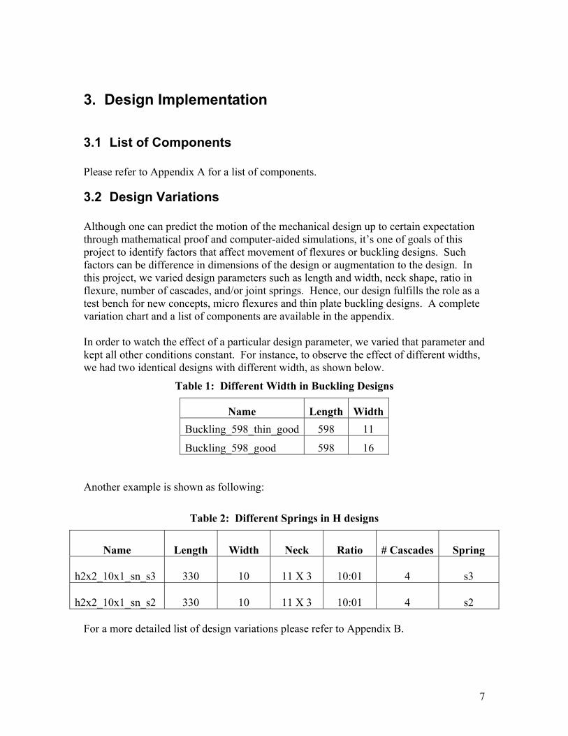
3.3 Pulling Mechanisms We need to note how designs respond to several different pulling mechanisms. These mechanisms should provide reliable, zero-backlash force to designs. In this project, we use three kinds of pulling mechanisms – pull-rings, heatuators, and linear stepper motor.
1) Pull-ring
The pull-rings is the most simple and fundamental element of pulling mechanisms available. A pull-ring enables a researcher to stick a probe into a pulling and pull flexures or buckling designs. The advantages of it are that it’s simple, guaranteed to work, and easy to operate. On the other hand, its movement is inaccurate and not precise. Another drawback is its large size in the aspect of chip real-estate. A screen capture of a pull-ring is shown below:
Figure 10: Pull-ring with a Basic Design
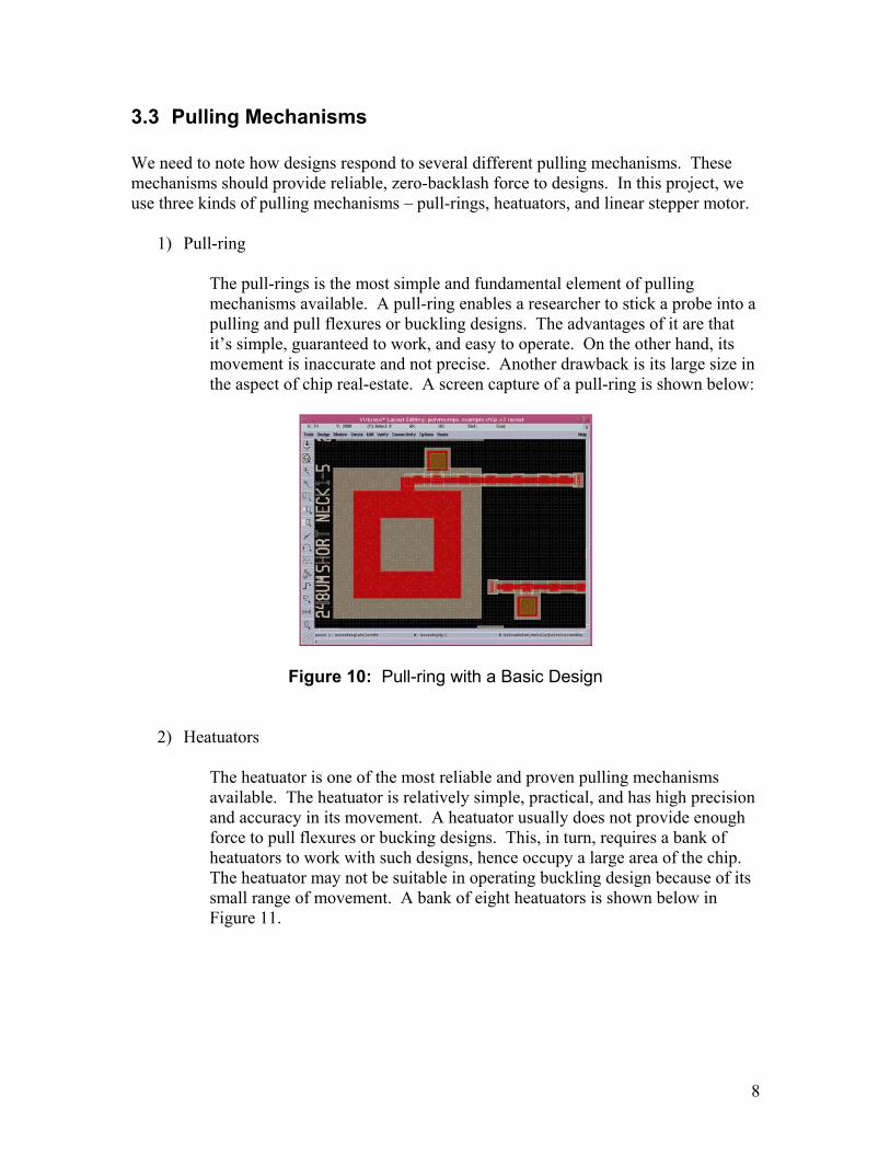
2) Heatuators
The heatuator is one of the most reliable and proven pulling mechanisms available. The heatuator is relatively simple, practical, and has high precision and accuracy in its movement. A heatuator usually does not provide enough force to pull flexures or bucking designs. This, in turn, requires a bank of heatuators to work with such designs, hence occupy a large area of the chip. The heatuator may not be suitable in operating buckling design because of its small range of movement. A bank of eight heatuators is shown below in Figure 11.
8
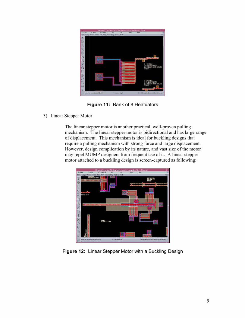
Figure 11: Bank of 8 Heatuators
3) Linear Stepper Motor
The linear stepper motor is another practical, well-proven pulling mechanism. The linear stepper motor is bidirectional and has large range of displacement. This mechanism is ideal for buckling designs that require a pulling mechanism with strong force and large displacement. However, design complication by its nature, and vast size of the motor may repel MUMP designers from frequent use of it. A linear stepper motor attached to a buckling design is screen-captured as following:
Figure 12: Linear Stepper Motor with a Buckling Design
9
3.4 Motion Predictions
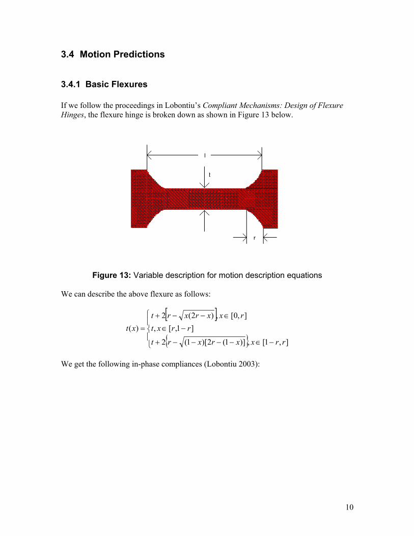
3.4.1 Basic Flexures If we follow the proceedings in Lobontiu’s Compliant Mechanisms: Design of Flexure Hinges, the flexure hinge is broken down as shown in Figure 13 below.
Figure 13: Variable description for motion description equations
We can describe the above flexure as follows:
[ ]
{ }
−∈−−−−+
−∈
∈−−+
=
],1[,)]1(2)[1(2
]1,[,],0[,)2(2
)(
rrxxrxrt
rrxtrxxrxrt
xt
We get the following in-phase compliances (Lobontiu 2003):
10
++
+++−−−+−
++++
+
+
++++++−+−+
+
+−−++
+
++++−++
+−−
=
−+
++
+−
=
−
−
tr
trttrttrtrrrltr
trtrttrtrrl
trt
trttrtrtrlrr
trttrtrtrtr
trt
rttrrlrtt
rlrlrl
EwC
tr
lrtlr
trl
EwC
y
x
Fy
Fx
41arctan)4(
]8148)(24)[2()4)(2(
)46(4
)4(22
)21(2)23(412)2(840
)4(
41arctan)46()2(
)4(4
])23(82480[)4(3
))(2(4
3
241arctan
)4()2(221
55
4322322
22
222
22
4322324
55
223
55
4334
3
22
,1
,1
πππ
ππ
π
It is apparent from the above equations that any further calculations are beyond the scope of this report. We invite the reader to formulate their own predictions from the above material.
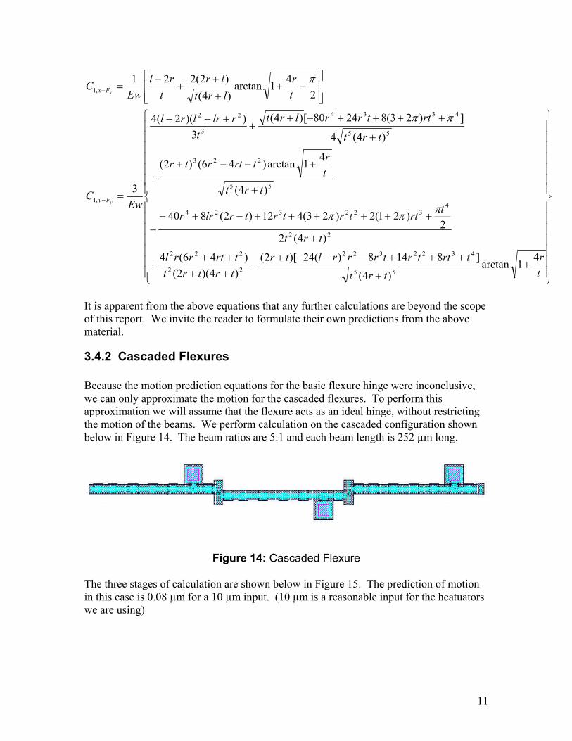
3.4.2 Cascaded Flexures Because the motion prediction equations for the basic flexure hinge were inconclusive, we can only approximate the motion for the cascaded flexures. To perform this approximation we will assume that the flexure acts as an ideal hinge, without restricting the motion of the beams. We perform calculation on the cascaded configuration shown below in Figure 14. The beam ratios are 5:1 and each beam length is 252 µm long.
Figure 14: Cascaded Flexure
The three stages of calculation are shown below in Figure 15. The prediction of motion in this case is 0.08 µm for a 10 µm input. (10 µm is a reasonable input for the heatuators we are using)
11
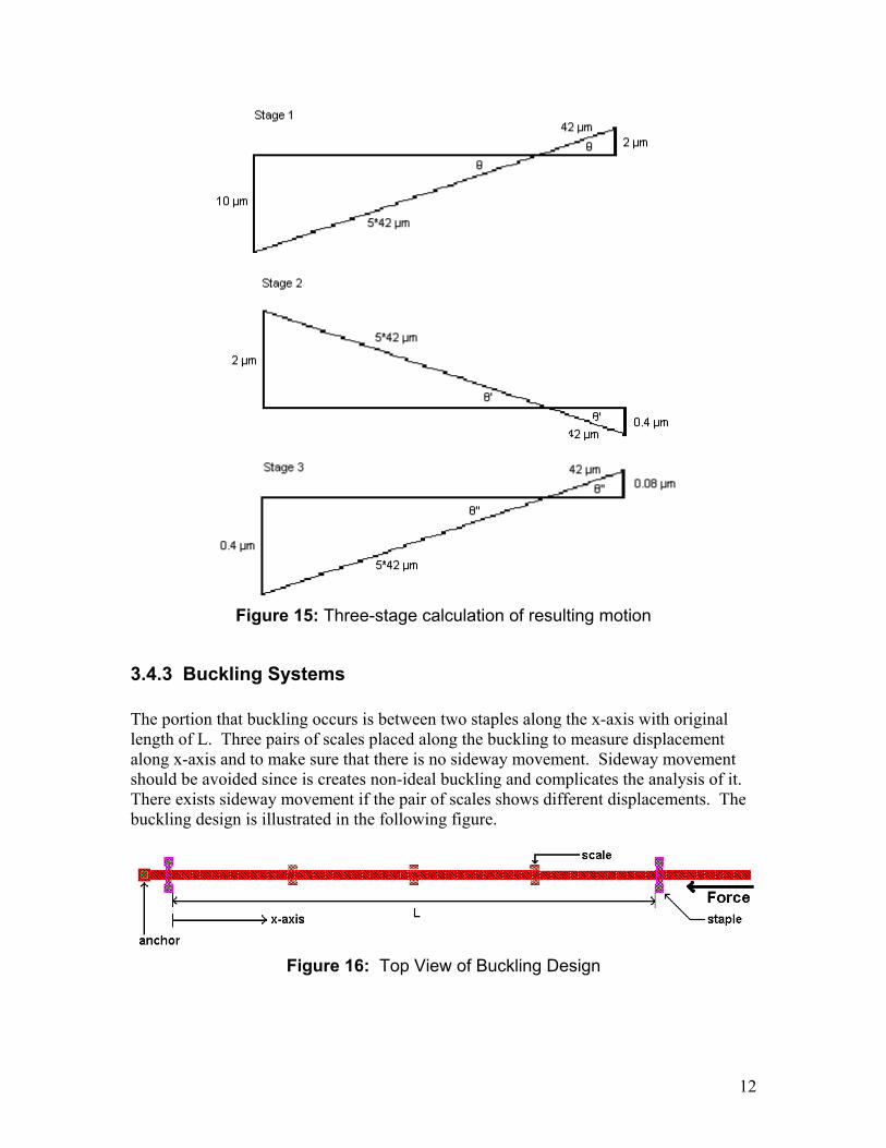
Figure 15: Three-stage calculation of resulting motion
3.4.3 Buckling Systems The portion that buckling occurs is between two staples along the x-axis with original length of L. Three pairs of scales placed along the buckling to measure displacement along x-axis and to make sure that there is no sideway movement. Sideway movement should be avoided since is creates non-ideal buckling and complicates the analysis of it. There exists sideway movement if the pair of scales shows different displacements. The buckling design is illustrated in the following figure.
Figure 16: Top View of Buckling Design
12
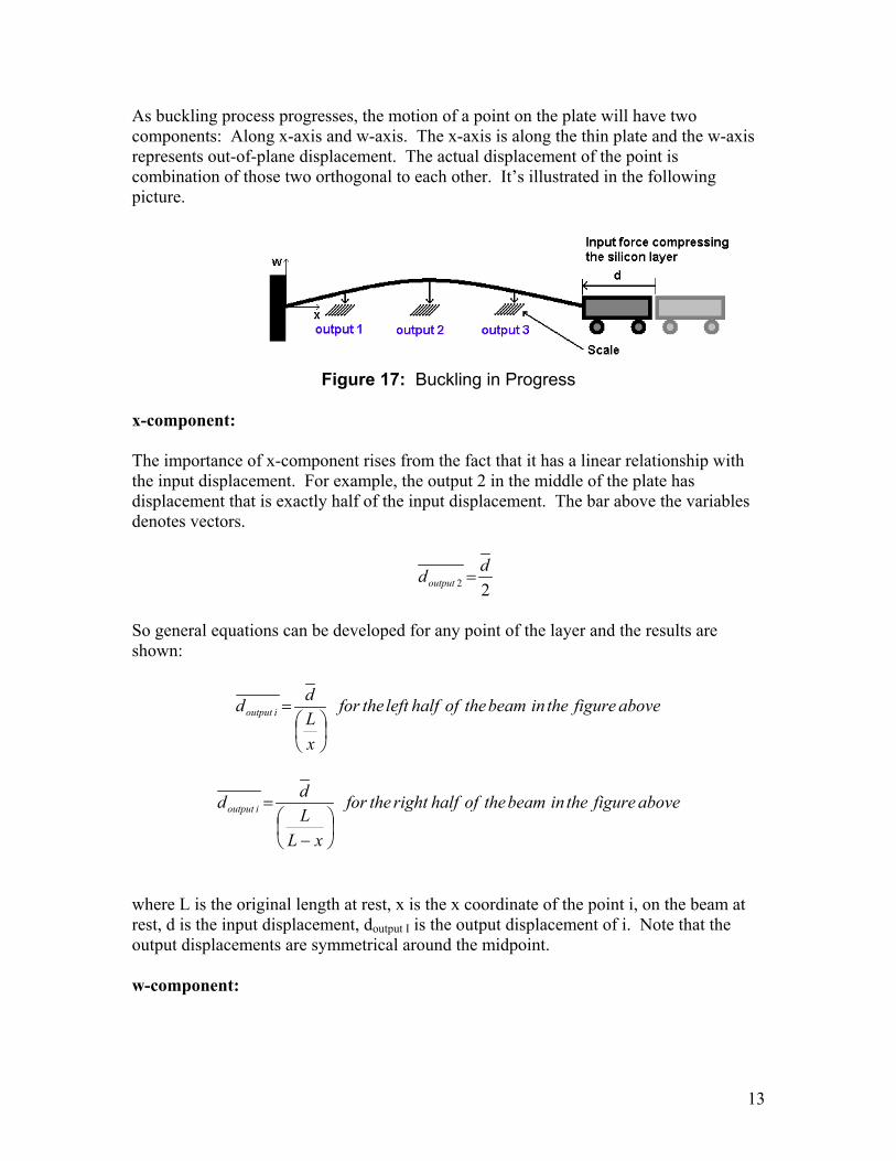
As buckling process progresses, the motion of a point on the plate will have two components: Along x-axis and w-axis. The x-axis is along the thin plate and the w-axis represents out-of-plane displacement. The actual displacement of the point is combination of those two orthogonal to each other. It’s illustrated in the following picture.
Figure 17: Buckling in Progress
x-component: The importance of x-component rises from the fact that it has a linear relationship with the input displacement. For example, the output 2 in the middle of the plate has displacement that is exactly half of the input displacement. The bar above the variables denotes vectors.
22ddoutput =
So general equations can be developed for any point of the layer and the results are shown:
abovefiguretheinbeamtheofhalfleftthefor
xLdd ioutput
=
abovefiguretheinbeamtheofhalfrightthefor
xLLdd ioutput
−
=
where L is the original length at rest, x is the x coordinate of the point i, on the beam at rest, d is the input displacement, doutput I is the output displacement of i. Note that the output displacements are symmetrical around the midpoint. w-component:
13
The movement in w direction (out-of-plane) exhibits very non-linear, unpredictable behavior with large backlash. Many literatures in post buckling behavior recognize that the plate buckles up, the peak reaches at wmax, and settle down at w*, which is the equilibrium point that’s lower than wmax. This translates to backlash which is highly avoided in this project. The linear model without imperfection gives w* as following (Fang 1994):
−≈
Lxww π2cos15.0* max
This equation itself shows that the w-component movement doesn’t exhibit linear motion. In addition to that, more non-linearity and imperfections will be added in real experiment due to fabrication defects, process temperature, etc. Hence, this out-of-plane motion is not a suitable output for almost all applications where predictability of the output is expected. Combination of x and w components (Actual displacement): Although x-component is linear, w-component demonstrates non-linearity which ultimately makes the combination of two, the actual displacement non-linear. So this is not a suitable output either. So, consequently, the best choice as the output is x-component of the point of movement, which is linear and well-defined with zero-backlash.
3.5 Design Issues Because the technology we are using is still in its infancy, we are fully aware that design issues are inevitable. We will discuss some of these design issues, but we can by no means predict all of them. Although we can attempt to predict the motion of the flexure hinges, the motion is only linear over a small range of motion. Because our designs are of micro proportions, even an infinitesimal motion can nudge the flexure outside of its linear range. We cannot guarantee against breakage in our designs: if the force exceeds a certain limit the material will likely break. All of our designs (other than buckling) assume that all motion will be in plane, when this is not actually the case. One challenge we expect to face when the chip returns from fabrication is that some of the motions are on such a small scale that they may not be easily observed. We may have to come up with an observation scheme beyond the 2 micron spaced 10 micron scales. One unexpected design issue that was pointed out to us after submittal of the final design, was that our linear stepper motors (LSMs) are reversed. This oversight is not fatal; although the range of motion of the LSMs is severely limited, we should still be able to see some results.
14
We are unfamiliar with the design of polysilicon mechanisms so we expect that we have overlooked some of its properties, which may affect the expected outcomes of our designs. Also, because the PolyMUMPs process works on such a small scale, we cannot be sure that the outcome of the process will even be what we expect. We cannot be certain how any of these design issues will affect our designs, but will be able to determine the effects after a thorough examination of the chip.
4. Future Research We hope that the designs we have just outlined will lead to new and significant research. We would like to steer our research into the following directions:
1) Based on the results from the buckling designs, we would like to experiment with different shapes of mechanisms to determine how shape affects buckling properties.
2) We would like to find a more reliable means of measuring the buckling results and making use of the buckling designs in other systems.
3) We would like to compile meaningful results from the flexure test bench and add to these results by experimenting with additional shapes of flexure hinges.
4) We would like to look into incorporating flexure hinges into existing designs that currently make use of pin-joints.
5. Conclusion Possible future applications of our flexure and buckling designs are not fully exploited yet. The main area of interest is probably where it requires high precision movement without backlash. Such requirements in some areas, such as the probe in SEMs, are currently fulfilled by exceedingly expensive devices utilizing electromagnetism. Successful implementation of our designs can address this problem. Numerous variations of basic flexures and buckling designs are created that sum up to more than 50 permutations. They are also set in action by manual pull-rings, heatuators, or linear stepper motor. Variations in design and pulling mechanism give us sufficient information on how different design considerations can affect the operation of the design. We were able to make predictions on the movement of designs based on simplified calculations with some assumptions. These predictions did not deal with all the possible non-linearity and imperfection originated from fabrication defects, temperature conditions, or complexity of the system that we could not address correctly due to our inexperience. Although this may deviate the actual performance of the design from its prediction, we are confident that our unique designs provide enough information for future generations to improve on such devices.
15
6. References Bloom, Frederick & Coffin, Douglas. 2001. Handbook of Thin Plate Buckling and
Postbuckling. Boca Raton, Florida, USA: CRC Press LLC.
Engineering Fundamentals. efunda.com/home.cfm (accessed July & August 2003)
Fang, W. & Wickert, J.A. 1994. “Post-buckling of Micromachined Beams,” Journal of
Micromechanics and Microengineering, Vol 4, pp 116-122.
Koester, David et al. 2003. PolyMUMPs Design Handbook.
http://www.ensc.sfu.ca/people/faculty/parameswaran/personal/494/polymumps-
V9.pdf: MEMSCAP.
Lobontiu, Nicolae. 2003. Compliant Mechanisms: Design of Flexure Hinges. Boca
Raton, Florida, USA: CRC Press LLC.
Smith, Stuart T. 2000. Flexure: Elements of Elastic Mechanisms. Singapore: Overseas
Publishers Association N.V.
16
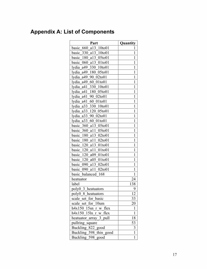
Appendix A: List of Components
Part Quantitybasic_660_a13_10to01 1basic_330_a13_10to01 1basic_180_a13_05to01 1basic_060_a13_01to01 1lydia_a49_330_10to01 1lydia_a49_180_05to01 1lydia_a49_90_02to01 1lydia_a49_60_01to01 1lydia_a41_330_10to01 1lydia_a41_180_05to01 1lydia_a41_90_02to01 1lydia_a41_60_01to01 1lydia_a33_330_10to01 1lydia_a33_120_05to01 1lydia_a33_90_02to01 1lydia_a33_60_01to01 1basic_360_a13_05to01 1basic_360_a11_05to01 1basic_180_a13_02to01 1basic_180_a11_02to01 1basic_120_a13_01to01 1basic_120_a11_01to01 1basic_120_a09_01to01 1basic_120_a05_01to01 1basic_090_a13_02to01 1basic_090_a11_02to01 1basic_balanced_168 1heatuator 24label 138poly0_3_heatuators 9poly0_8_heatuators 12scale_set_for_basic 33scale_set_for_10um 20h4x150_15sn_r_w_flex 1h4x150_15ln_r_w_flex 1heatuator_array_3_pull 18pullring_square 53Buckling_822_good 3Buckling_598_thin_good 1Buckling_598_good 1
17
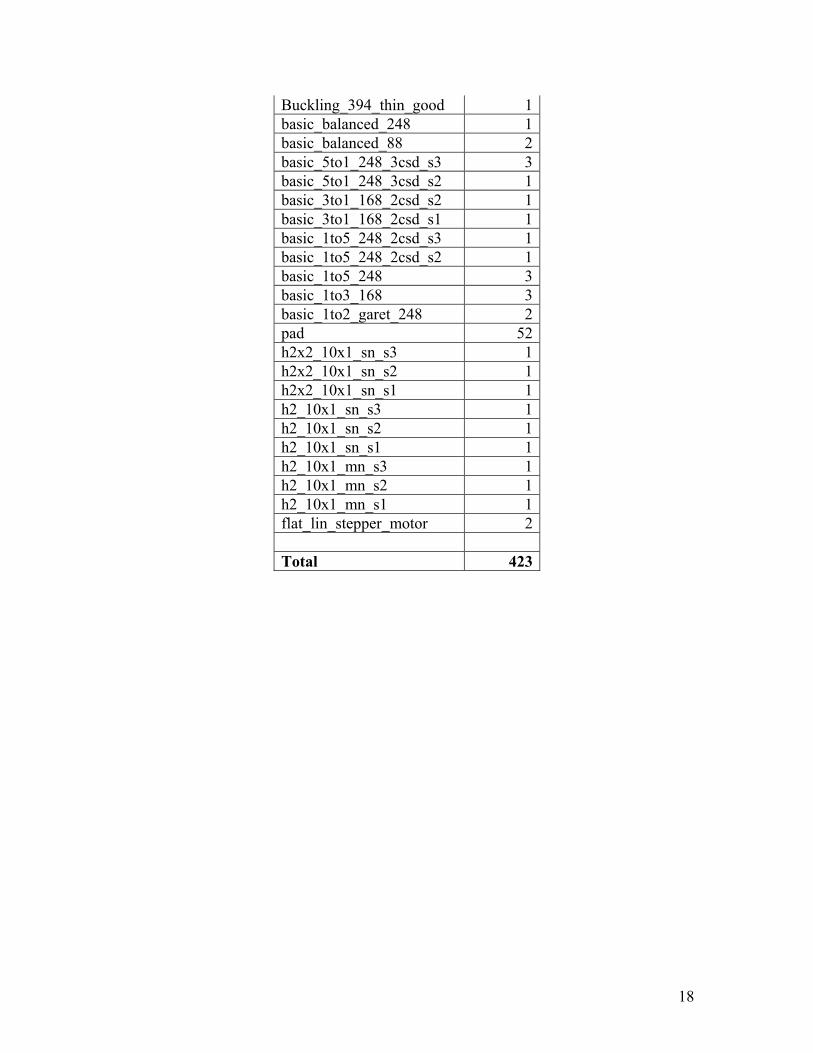
Buckling_394_thin_good 1basic_balanced_248 1basic_balanced_88 2basic_5to1_248_3csd_s3 3basic_5to1_248_3csd_s2 1basic_3to1_168_2csd_s2 1basic_3to1_168_2csd_s1 1basic_1to5_248_2csd_s3 1basic_1to5_248_2csd_s2 1basic_1to5_248 3basic_1to3_168 3basic_1to2_garet_248 2pad 52h2x2_10x1_sn_s3 1h2x2_10x1_sn_s2 1h2x2_10x1_sn_s1 1h2_10x1_sn_s3 1h2_10x1_sn_s2 1h2_10x1_sn_s1 1h2_10x1_mn_s3 1h2_10x1_mn_s2 1h2_10x1_mn_s1 1flat_lin_stepper_motor 2 Total 423
18
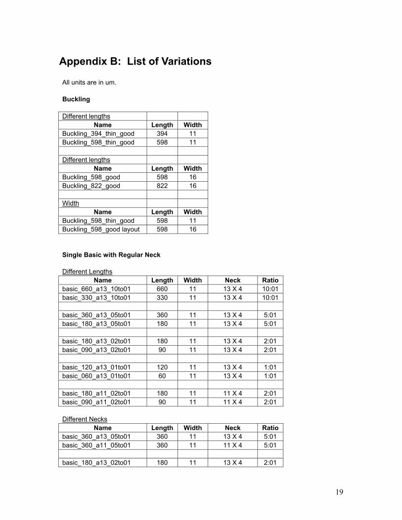
Appendix B: List of Variations All units are in um. Buckling Different lengths
Name Length Width Buckling_394_thin_good 394 11 Buckling_598_thin_good 598 11 Different lengths
Name Length Width Buckling_598_good 598 16 Buckling_822_good 822 16 Width
Name Length Width Buckling_598_thin_good 598 11 Buckling_598_good layout 598 16 Single Basic with Regular Neck Different Lengths
Name Length Width Neck Ratio basic_660_a13_10to01 660 11 13 X 4 10:01 basic_330_a13_10to01 330 11 13 X 4 10:01 basic_360_a13_05to01 360 11 13 X 4 5:01 basic_180_a13_05to01 180 11 13 X 4 5:01 basic_180_a13_02to01 180 11 13 X 4 2:01 basic_090_a13_02to01 90 11 13 X 4 2:01 basic_120_a13_01to01 120 11 13 X 4 1:01 basic_060_a13_01to01 60 11 13 X 4 1:01 basic_180_a11_02to01 180 11 11 X 4 2:01 basic_090_a11_02to01 90 11 11 X 4 2:01 Different Necks
Name Length Width Neck Ratio basic_360_a13_05to01 360 11 13 X 4 5:01 basic_360_a11_05to01 360 11 11 X 4 5:01 basic_180_a13_02to01 180 11 13 X 4 2:01
19
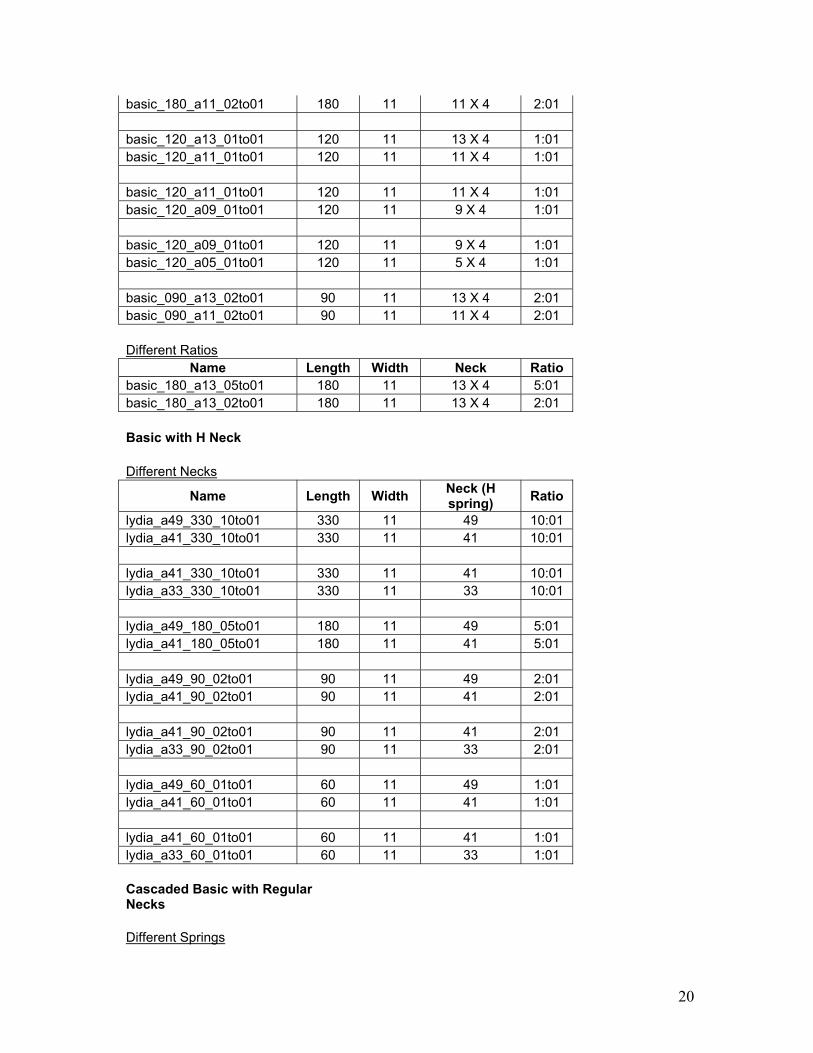
basic_180_a11_02to01 180 11 11 X 4 2:01 basic_120_a13_01to01 120 11 13 X 4 1:01 basic_120_a11_01to01 120 11 11 X 4 1:01 basic_120_a11_01to01 120 11 11 X 4 1:01 basic_120_a09_01to01 120 11 9 X 4 1:01 basic_120_a09_01to01 120 11 9 X 4 1:01 basic_120_a05_01to01 120 11 5 X 4 1:01 basic_090_a13_02to01 90 11 13 X 4 2:01 basic_090_a11_02to01 90 11 11 X 4 2:01 Different Ratios
Name Length Width Neck Ratio basic_180_a13_05to01 180 11 13 X 4 5:01 basic_180_a13_02to01 180 11 13 X 4 2:01 Basic with H Neck Different Necks
Name Length Width Neck (H spring) Ratio
lydia_a49_330_10to01 330 11 49 10:01 lydia_a41_330_10to01 330 11 41 10:01 lydia_a41_330_10to01 330 11 41 10:01 lydia_a33_330_10to01 330 11 33 10:01 lydia_a49_180_05to01 180 11 49 5:01 lydia_a41_180_05to01 180 11 41 5:01 lydia_a49_90_02to01 90 11 49 2:01 lydia_a41_90_02to01 90 11 41 2:01 lydia_a41_90_02to01 90 11 41 2:01 lydia_a33_90_02to01 90 11 33 2:01 lydia_a49_60_01to01 60 11 49 1:01 lydia_a41_60_01to01 60 11 41 1:01 lydia_a41_60_01to01 60 11 41 1:01 lydia_a33_60_01to01 60 11 33 1:01 Cascaded Basic with Regular Necks
Different Springs
20
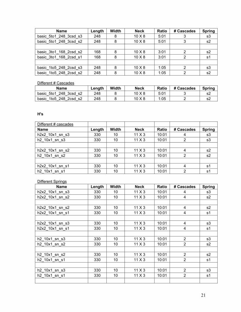
Name Length Width Neck Ratio # Cascades Spring basic_5to1_248_3csd_s3 248 8 10 X 8 5:01 3 s3 basic_5to1_248_3csd_s2 248 8 10 X 8 5:01 3 s2 basic_3to1_168_2csd_s2 168 8 10 X 8 3:01 2 s2 basic_3to1_168_2csd_s1 168 8 10 X 8 3:01 2 s1 basic_1to5_248_2csd_s3 248 8 10 X 8 1:05 2 s3 basic_1to5_248_2csd_s2 248 8 10 X 8 1:05 2 s2 Different # Cascades
Name Length Width Neck Ratio # Cascades Spring basic_5to1_248_3csd_s2 248 8 10 X 8 5:01 3 s2 basic_1to5_248_2csd_s2 248 8 10 X 8 1:05 2 s2 H's Different # cascades Name Length Width Neck Ratio # Cascades Spring h2x2_10x1_sn_s3 330 10 11 X 3 10:01 4 s3 h2_10x1_sn_s3 330 10 11 X 3 10:01 2 s3 h2x2_10x1_sn_s2 330 10 11 X 3 10:01 4 s2 h2_10x1_sn_s2 330 10 11 X 3 10:01 2 s2 h2x2_10x1_sn_s1 330 10 11 X 3 10:01 4 s1 h2_10x1_sn_s1 330 10 11 X 3 10:01 2 s1 Different Springs
Name Length Width Neck Ratio # Cascades Spring h2x2_10x1_sn_s3 330 10 11 X 3 10:01 4 s3 h2x2_10x1_sn_s2 330 10 11 X 3 10:01 4 s2 h2x2_10x1_sn_s2 330 10 11 X 3 10:01 4 s2 h2x2_10x1_sn_s1 330 10 11 X 3 10:01 4 s1 h2x2_10x1_sn_s3 330 10 11 X 3 10:01 4 s3 h2x2_10x1_sn_s1 330 10 11 X 3 10:01 4 s1 h2_10x1_sn_s3 330 10 11 X 3 10:01 2 s3 h2_10x1_sn_s2 330 10 11 X 3 10:01 2 s2 h2_10x1_sn_s2 330 10 11 X 3 10:01 2 s2 h2_10x1_sn_s1 330 10 11 X 3 10:01 2 s1 h2_10x1_sn_s3 330 10 11 X 3 10:01 2 s3 h2_10x1_sn_s1 330 10 11 X 3 10:01 2 s1
21
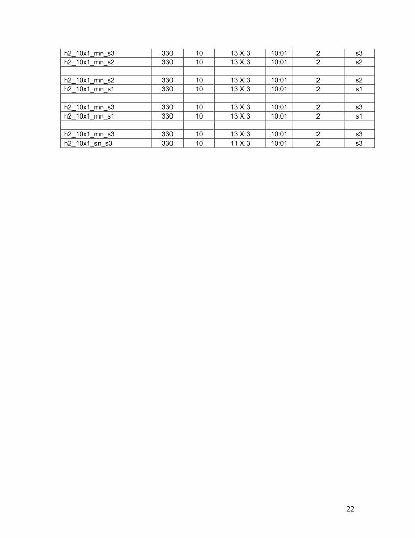
22
h2_10x1_mn_s3 330 10 13 X 3 10:01 2 s3 h2_10x1_mn_s2 330 10 13 X 3 10:01 2 s2 h2_10x1_mn_s2 330 10 13 X 3 10:01 2 s2 h2_10x1_mn_s1 330 10 13 X 3 10:01 2 s1 h2_10x1_mn_s3 330 10 13 X 3 10:01 2 s3 h2_10x1_mn_s1 330 10 13 X 3 10:01 2 s1 h2_10x1_mn_s3 330 10 13 X 3 10:01 2 s3 h2_10x1_sn_s3 330 10 11 X 3 10:01 2 s3