enhancement of transient stability using fault current limiter …ee04109/documentos e...
TRANSCRIPT
> 57 <
1
Abstract—This paper presents the results of analyses about
transient stability enhancement using both devices-the fault current limiter and the thyristor controlled braking resistor. Following a major disturbance in power system, the fault current limiter operates for limiting of the fault current, enhancement of the transient stability and suppression of the turbine shaft torsional oscillation, and then the thyristor controlled braking resistor operates with the objective of fast control of generator disturbances. The effectiveness of both devices has been demonstrated by considering 3LG (three-phase-to-ground) fault at 12 fault points in a two-machine infinite bus system. The simulation results indicate a significant transient stability enhancement and damping shaft torsional oscillations.
Index Terms—Fault current limiter, power system transient stability, thyristor controlled braking resistor, turbine shaft torsional torque
I. INTRODUCTION ITH the increasing demand for electric power, power systems are becoming larger and more interconnected.
As a consequence, the fault current increase, and transient stability problems become more serious. Consequently, in order to maintain the stability of power system, replacement of substation equipment or changes in the configuration of the system will be needed, and this ultimately leads to decreased operational flexibility and lower reliability.
The use of Fault Current Limiters (FCLs) is being evaluated as one element necessary to limit the fault current and enhance the power system transient stability [1]-[3]. FCL is a device that limits the fault current by generating an impedance when a fault occurs. In addition, the limiting impedance generated to limit fault currents proves helpful in increasing generator output degraded by a fault, thus providing stabilization. However, as FCLs installed in series with transmission lines can be just operated during the period from the fault occurrence to the fault clearing, they cannot control the generator disturbances after the clearing of fault. M.Yagami is with the Department of Electrical and Electronic Engineering, Hokkaido Institute of Technology, Sapporo, JAPAN (e-mail: [email protected]). J.Tamura is with the Department of Electrical and Electronic Engineering, Kitami Institute of Technology, Kitami, JAPAN (e-mail: [email protected]).
The Braking Resistor (BR) is also known as a very effective device for transient stability control. It can be viewed as a fast load injection to absorb excess transient energy which arises due to system disturbances. Besides, with the recent development of power electronics technology, replacing the circuit breaker with the semiconductor device is becoming feasible. Several thyristor-based control techniques [4],[5] have been proposed in the literature for the switching of BR. Since the thyristor controlled braking resistor (TCBR) can control the accelerating power in generators with flexibility, the power system stability is enhanced more than that of the use of BR controlled by mechanical device. However, as BR is installed in parallel with the transmission lines, BR cannot be operated before the clearing of faults.
From these viewpoints, in this paper, we have proposed the use of both devices-FCL and TCBR for the purpose of a significant transient stability enhancement. If both devices-FCL and TCBR operate at the same bus, the stabilization control scheme can be carried out continuously and with flexibility for a long duration (i.e., FCL operates from the fault occurrence instance to the fault clearing, and then TCBR operates dynamically until the generator disturbance becomes small). Through the simulation results, the effectiveness of the use of both devices on transient stability enhancement is demonstrated. This paper also presents the effectiveness of the use of both devices on suppression of the turbine shaft torsional oscillations. Simulations are performed using EMTP/ATP.
II. POWER SYSTEM MODEL
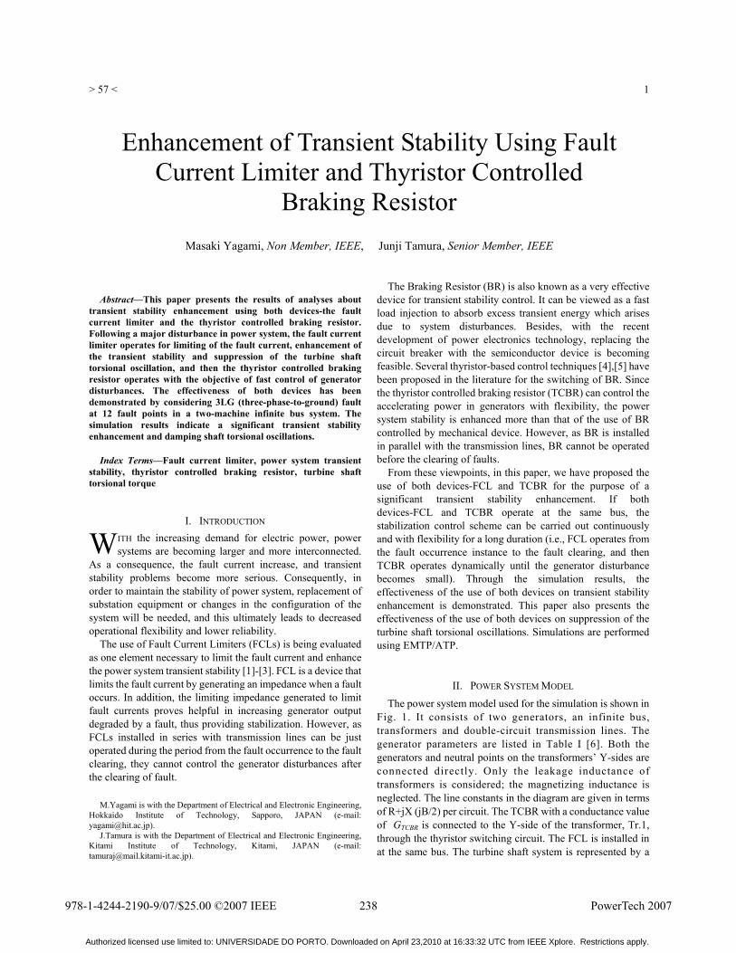
The power system model used for the simulation is shown in Fig. 1. It consists of two generators, an infinite bus, transformers and double-circuit transmission lines. The generator parameters are listed in Table I [6]. Both the generators and neutral points on the transformers’ Y-sides are connected directly. Only the leakage inductance of transformers is considered; the magnetizing inductance is neglected. The line constants in the diagram are given in terms of R+jX (jB/2) per circuit. The TCBR with a conductance value of GTCBR is connected to the Y-side of the transformer, Tr.1, through the thyristor switching circuit. The FCL is installed in at the same bus. The turbine shaft system is represented by a
Enhancement of Transient Stability Using Fault Current Limiter and Thyristor Controlled
Braking Resistor Masaki Yagami, Non Member, IEEE, Junji Tamura, Senior Member, IEEE
W
238978-1-4244-2190-9/07/$25.00 ©2007 IEEE PowerTech 2007
Authorized licensed use limited to: UNIVERSIDADE DO PORTO. Downloaded on April 23,2010 at 16:33:32 UTC from IEEE Xplore. Restrictions apply.
> 57 <
2
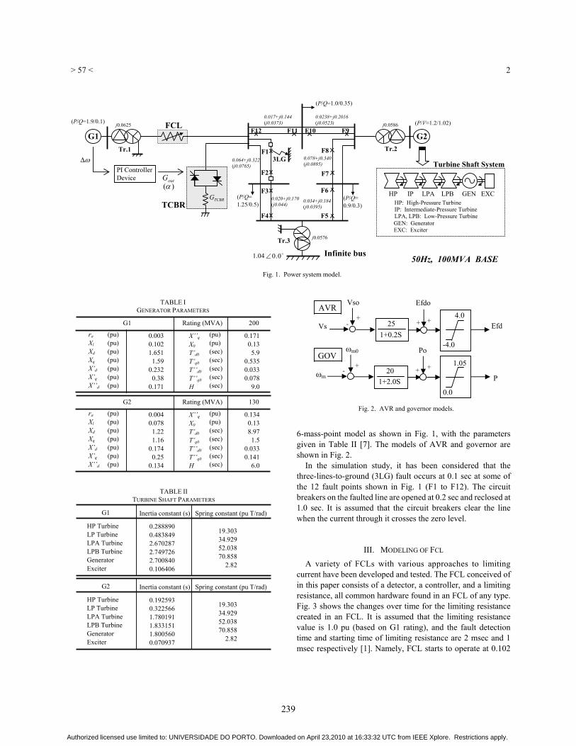
6-mass-point model as shown in Fig. 1, with the parameters given in Table II [7]. The models of AVR and governor are shown in Fig. 2.
In the simulation study, it has been considered that the three-lines-to-ground (3LG) fault occurs at 0.1 sec at some of the 12 fault points shown in Fig. 1 (F1 to F12). The circuit breakers on the faulted line are opened at 0.2 sec and reclosed at 1.0 sec. It is assumed that the circuit breakers clear the line when the current through it crosses the zero level.
III. MODELING OF FCL
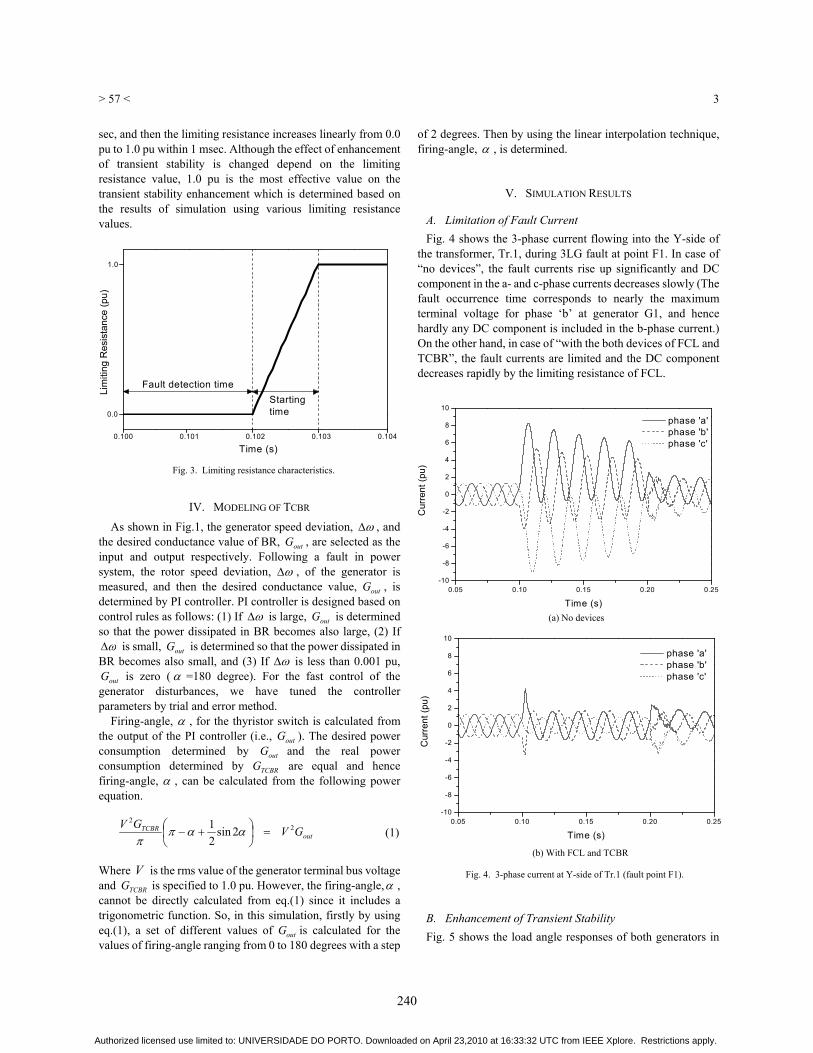
A variety of FCLs with various approaches to limiting current have been developed and tested. The FCL conceived of in this paper consists of a detector, a controller, and a limiting resistance, all common hardware found in an FCL of any type. Fig. 3 shows the changes over time for the limiting resistance created in an FCL. It is assumed that the limiting resistance value is 1.0 pu (based on G1 rating), and the fault detection time and starting time of limiting resistance are 2 msec and 1 msec respectively [1]. Namely, FCL starts to operate at 0.102
Fig. 1. Power system model.
F3 F6
F83LG
Tr.1
(P/Q=1.9/0.1)
(P/Q= 1.25/0.5)
F2
F1
(P/Q=1.0/0.35)
0.0238+j0.2016 (j0.0523)
G1 j0.0625
G2
(P/V=1.2/1.02) 0.017+j0.144 (j0.0373)
(P/Q= 0.9/0.3)
0.020+j0.170 (j0.044)
0.034+j0.184 (j0.0395)
0.064+j0.322 (j0.0765)
0.078+j0.340 (j0.0895)
j0.0586
j0.0576
Infinite bus
Tr.2
F7
Tr.3
1.04 0.0
FCL
TCBRGTCBR
PI Controller Device
outG
HP IP LPA LPB GEN EXC HP: High-Pressure Turbine IP: Intermediate-Pressure Turbine LPA, LPB: Low-Pressure Turbine GEN: Generator EXC: Exciter
F4 F5
F12 F11 F10 F9
50Hz, 100MVA BASE
Turbine Shaft System
)(
(pu) (pu) (sec) (sec) (sec) (sec) (sec)
X’’q
X0
T’d0
T’q0
T’’d0
T’’q0
H
200
(pu) (pu) (pu) (pu) (pu) (pu) (pu)
G1
ra
Xl
Xd
Xq
X’d
X’q
X’’d
0.003 0.102 1.651
1.59
0.232
0.38
0.171
0.1710.13
5.90.5350.0330.078
9.0
Rating (MVA)
(pu) (pu) (sec) (sec) (sec) (sec) (sec)
X’’q
X0
T’d0
T’q0
T’’d0
T’’q0
H
130
(pu) (pu) (pu) (pu) (pu) (pu) (pu)
G2
ra
Xl
Xd
Xq
X’d
X’q
X’’d
0.004 0.078
1.22
1.16
0.174
0.25
0.134
0.1340.138.97
1.50.0330.141
6.0
Rating (MVA)
TABLE I GENERATOR PARAMETERS
19.303 34.929 52.038 70.858
2.82
HP Turbine LP Turbine LPA Turbine LPB Turbine Generator Exciter
Inertia constant (s) Spring constant (pu T/rad)
0.288890 0.483849 2.670287 2.749726 2.700840 0.106406
G1
19.303 34.929 52.038 70.858
2.82
HP Turbine LP Turbine LPA Turbine LPB Turbine Generator Exciter
Inertia constant (s) Spring constant (pu T/rad)
0.192593 0.322566 1.780191 1.833151 1.800560 0.070937
G2
TABLE II TURBINE SHAFT PARAMETERS
P
Efd
Vso
Vs+
- 251+0.2S
Efdo
+ + 4.0
-4.0
AVR
GOV
1+2.0S 20 + + 1.05
0.0
Po
- +
m0
m
Fig. 2. AVR and governor models.
239
Authorized licensed use limited to: UNIVERSIDADE DO PORTO. Downloaded on April 23,2010 at 16:33:32 UTC from IEEE Xplore. Restrictions apply.
> 57 <
3
sec, and then the limiting resistance increases linearly from 0.0 pu to 1.0 pu within 1 msec. Although the effect of enhancement of transient stability is changed depend on the limiting resistance value, 1.0 pu is the most effective value on the transient stability enhancement which is determined based on the results of simulation using various limiting resistance values.
IV. MODELING OF TCBR
As shown in Fig.1, the generator speed deviation, , and the desired conductance value of BR, outG , are selected as the input and output respectively. Following a fault in power system, the rotor speed deviation, , of the generator is measured, and then the desired conductance value, outG , is determined by PI controller. PI controller is designed based on control rules as follows: (1) If is large, outG is determined so that the power dissipated in BR becomes also large, (2) If
is small, outG is determined so that the power dissipated in BR becomes also small, and (3) If is less than 0.001 pu,
outG is zero ( =180 degree). For the fast control of the generator disturbances, we have tuned the controller parameters by trial and error method.
Firing-angle, , for the thyristor switch is calculated from the output of the PI controller (i.e., outG ). The desired power consumption determined by outG and the real power consumption determined by TCBRG are equal and hence firing-angle, , can be calculated from the following power equation. Where V is the rms value of the generator terminal bus voltage and TCBRG is specified to 1.0 pu. However, the firing-angle, , cannot be directly calculated from eq.(1) since it includes a trigonometric function. So, in this simulation, firstly by using eq.(1), a set of different values of outG is calculated for the values of firing-angle ranging from 0 to 180 degrees with a step
of 2 degrees. Then by using the linear interpolation technique, firing-angle, , is determined.
V. SIMULATION RESULTS
A. Limitation of Fault Current Fig. 4 shows the 3-phase current flowing into the Y-side of
the transformer, Tr.1, during 3LG fault at point F1. In case of “no devices”, the fault currents rise up significantly and DC component in the a- and c-phase currents decreases slowly (The fault occurrence time corresponds to nearly the maximum terminal voltage for phase ‘b’ at generator G1, and hence hardly any DC component is included in the b-phase current.) On the other hand, in case of “with the both devices of FCL and TCBR”, the fault currents are limited and the DC component decreases rapidly by the limiting resistance of FCL.
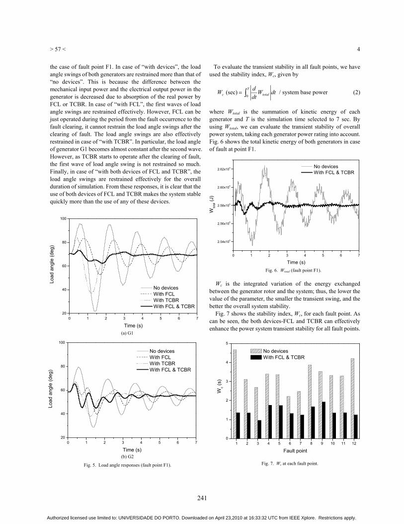
B. Enhancement of Transient Stability Fig. 5 shows the load angle responses of both generators in
outTCBR GV
GV 22
2sin21
(1)
0.100 0.101 0.102 0.103 0.104
1.0
0.0
Startingtime
Lim
iting
Res
ista
nce
(pu)
Time (s)
Fault detection time
Fig. 3. Limiting resistance characteristics.
0.05 0.10 0.15 0.20 0.25-10
-8
-6
-4
-2
0
2
4
6
8
10
Cur
rent
(pu)
Time (s)
phase 'a' phase 'b' phase 'c'
0.05 0.10 0.15 0.20 0.25-10
-8
-6
-4
-2
0
2
4
6
8
10
Cur
rent
(pu)
Time (s)
phase 'a' phase 'b' phase 'c'
Fig. 4. 3-phase current at Y-side of Tr.1 (fault point F1).
(a) No devices
(b) With FCL and TCBR
240
Authorized licensed use limited to: UNIVERSIDADE DO PORTO. Downloaded on April 23,2010 at 16:33:32 UTC from IEEE Xplore. Restrictions apply.
> 57 <
4
the case of fault point F1. In case of “with devices”, the load angle swings of both generators are restrained more than that of “no devices”. This is because the difference between the mechanical input power and the electrical output power in the generator is decreased due to absorption of the real power by FCL or TCBR. In case of “with FCL”, the first waves of load angle swings are restrained effectively. However, FCL can be just operated during the period from the fault occurrence to the fault clearing, it cannot restrain the load angle swings after the clearing of fault. The load angle swings are also effectively restrained in case of “with TCBR”. In particular, the load angle of generator G1 becomes almost constant after the second wave. However, as TCBR starts to operate after the clearing of fault, the first wave of load angle swing is not restrained so much. Finally, in case of “with both devices of FCL and TCBR”, the load angle swings are restrained effectively for the overall duration of simulation. From these responses, it is clear that the use of both devices of FCL and TCBR makes the system stable quickly more than the use of any of these devices.
To evaluate the transient stability in all fault points, we have used the stability index, Wc, given by where Wtotal is the summation of kinetic energy of each generator and T is the simulation time selected to 7 sec. By using Wtotal, we can evaluate the transient stability of overall power system, taking each generator power rating into account. Fig. 6 shows the total kinetic energy of both generators in case of fault at point F1.
Wc is the integrated variation of the energy exchanged between the generator rotor and the system; thus, the lower the value of the parameter, the smaller the transient swing, and the better the overall system stability. Fig. 7 shows the stability index, Wc, for each fault point. As can be seen, the both devices-FCL and TCBR can effectively enhance the power system transient stability for all fault points.
Ttotalc dtW
dtdW
0(sec) / system base power (2)
0 1 2 3 4 5 6 720
40
60
80
100
Load
ang
le (d
eg)
Time (s)
No devices With FCL With TCBR With FCL & TCBR
0 1 2 3 4 5 6 720
40
60
80
100
Load
ang
le (d
eg)
Time (s)
No devices With FCL With TCBR With FCL & TCBR
Fig. 5. Load angle responses (fault point F1).
(b) G2
(a) G1
0 1 2 3 4 5 6 7
2.54x10⁹
2.56x10⁹
2.58x10⁹
2.60x10⁹
2.62x10⁹
Wto
tal (J
)
Time (s)
No devices With FCL & TCBR
Fig. 6. Wtotal (fault point F1).
Fig. 7. Wc at each fault point.
1 2 3 4 5 6 7 8 9 10 11 120
1
2
3
4
5
Wc (s
)
Fault point
No devices With FCL & TCBR
241
Authorized licensed use limited to: UNIVERSIDADE DO PORTO. Downloaded on April 23,2010 at 16:33:32 UTC from IEEE Xplore. Restrictions apply.
> 57 <
5
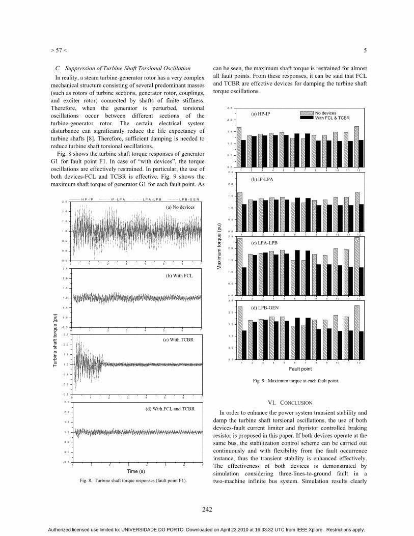
C. Suppression of Turbine Shaft Torsional Oscillation In reality, a steam turbine-generator rotor has a very complex
mechanical structure consisting of several predominant masses (such as rotors of turbine sections, generator rotor, couplings, and exciter rotor) connected by shafts of finite stiffness. Therefore, when the generator is perturbed, torsional oscillations occur between different sections of the turbine-generator rotor. The certain electrical system disturbance can significantly reduce the life expectancy of turbine shafts [8]. Therefore, sufficient damping is needed to reduce turbine shaft torsional oscillations.
Fig. 8 shows the turbine shaft torque responses of generator G1 for fault point F1. In case of “with devices”, the torque oscillations are effectively restrained. In particular, the use of both devices-FCL and TCBR is effective. Fig. 9 shows the maximum shaft torque of generator G1 for each fault point. As
can be seen, the maximum shaft torque is restrained for almost all fault points. From these responses, it can be said that FCL and TCBR are effective devices for damping the turbine shaft torque oscillations.
VI. CONCLUSION
In order to enhance the power system transient stability and damp the turbine shaft torsional oscillations, the use of both devices-fault current limiter and thyristor controlled braking resistor is proposed in this paper. If both devices operate at the same bus, the stabilization control scheme can be carried out continuously and with flexibility from the fault occurrence instance, thus the transient stability is enhanced effectively. The effectiveness of both devices is demonstrated by simulation considering three-lines-to-ground fault in a two-machine infinite bus system. Simulation results clearly
Time (s)
0 1 2 3 4 5 6 7- 0 . 5
0 . 0
0 . 5
1 . 0
1 . 5
2 . 0
2 . 5 H P - I P I P - L P A L P A - L P B L P B - G E N
0 1 2 3 4 5 6 7- 0 . 5
0 . 0
0 . 5
1 . 0
1 . 5
2 . 0
2 . 5
0 1 2 3 4 5 6 7- 0 . 5
0 . 0
0 . 5
1 . 0
1 . 5
2 . 0
2 . 5
0 1 2 3 4 5 6 7- 0 . 5
0 . 0
0 . 5
1 . 0
1 . 5
2 . 0
2 . 5
Turb
ine
shaf
t tor
que
(pu)
Fig. 8. Turbine shaft torque responses (fault point F1).
Max
imum
torq
ue (p
u)
Fig. 9. Maximum torque at each fault point.
Fault point
(a) No devices
(b) With FCL
(c) With TCBR
(d) With FCL and TCBR
(d) LPB-GEN
(c) LPA-LPB
(b) IP-LPA
(a) HP-IP
1 2 3 4 5 6 7 8 9 1 0 1 1 1 20 . 0
0 . 5
1 . 0
1 . 5
2 . 0
2 . 5
1 2 3 4 5 6 7 8 9 1 0 1 1 1 20 . 0
0 . 5
1 . 0
1 . 5
2 . 0
2 . 5
1 2 3 4 5 6 7 8 9 1 0 1 1 1 20 . 0
0 . 5
1 . 0
1 . 5
2 . 0
2 . 5
1 2 3 4 5 6 7 8 9 1 0 1 1 1 20 . 0
0 . 5
1 . 0
1 . 5
2 . 0
2 . 5
No devices With FCL & TCBR
242
Authorized licensed use limited to: UNIVERSIDADE DO PORTO. Downloaded on April 23,2010 at 16:33:32 UTC from IEEE Xplore. Restrictions apply.
> 57 <
6
indicate the significant enhancement of the transient stability and suppression of turbine shaft torsional oscillations.
REFERENCES [1] IEE Japan, “State-of-the art and trends in fault current limiting
technologies”, IEEJ Report, no.709, 1999. [2] E. Leung, “Superconducting fault current limiters”, IEEE Power
Engineering Review, pp.15-30, Aug. 2000. [3] M. Sjostrom, R.Cherkaoui and B.Dutoit, “Enhancement of power system
transient stability using superconducting fault current limiters”, IEEE Trans. Applied Superconductivity, vol.9, no.2, pp.1328-1330, 1999.
[4] H.Jiang, J.Dorsey, and T.Habetler, “A cost effective generator brake for improved generator transient response”, IEEE Trans. Power Systems, vol.9, no.4, pp.1840-1846, 1994.
[5] M.H.Ali, T.Murata, and J.Tamura, “An analysis of the fuzzy logic controlled braking resistor for transient stability improvement in multi-machine power system”, IEEJ Trans. PE. vol.124, no.4, pp.553-560, 2004.
[6] Y.Sekine, “Transient Analysis Theory of Power System”, Ohmu Press, 1989
[7] IEEE subsynchronous resonance task force of the dynamic system performance working group power system committee, “First benchmark model for computer simulation of subsynchronous resonance”, IEEE Trans. Power Apparatus System, vol. PAS-96, no.5, pp.1565-1572, 1977.
[8] P.Kundur, “Power system stability and control”, McGraw-Hill, 1994.
243
Authorized licensed use limited to: UNIVERSIDADE DO PORTO. Downloaded on April 23,2010 at 16:33:32 UTC from IEEE Xplore. Restrictions apply.