enhanced remote visual inspection of aircraft skin€¦ · remote and automated inspection: ......
TRANSCRIPT
Mel Siegel <[email protected]> / The Robotics Institute / Carnegie Mellon University /Pittsburgh PA 15213 USA / 412 268 8802 / FAX 412 268 5569Workshop on Intelligent NDE Sciences for Aging and Futuristic Aircraft / FAST Center for Structural Integrity of Aerospace SystemsUniversity of Texas at El Paso / 1997-September-30 to 1997-October-02Remote and Automated Inspection: Status and Prospects (“cimp_paper”) page 1 of 12 pages/usr/people/mws/mss/AgingAircraft/ElPaso97/cimp_paper/text/elp_cimp97t-aj.mkr as of September 29, 1997 12:21 pm
Enhanced remote visual inspection of aircraft skin*
Mel Siegela, Priyan Gunatilakeb
aThe Robotics Institute, School of Computer SciencebDepartment of Electrical and Computer Engineering
Carnegie Mellon University, Pittsburgh PA 15213 USA
ABSTRACTVisual inspection is the most widely used method in commercial aircraft surface inspection. We havedeveloped a prototype remote visual inspection system, designed to facilitate testing the feasibility andadvantages of remote visual inspection of aircraft surfaces. We describe experiments with image under-standing algorithms to aid remote visual inspection by enhancing and recognizing surface cracks and cor-rosion from live imagery. Also described are the supporting mobile robot platform that delivers theimagery, and the inspection console through which the inspector accesses it. We discuss initial results ofthe image understanding algorithms and speculate on their future use in aircraft surface inspection.
KEYWORDS: enhanced remote robotic visual inspection stereoscopic multiresolution ANDI CIMP
1. INTRODUCTIONVisual inspection of aircraft is the most widely used method employed for ensuring the structural integ-rity of an aircraft skin and its substructure. For example, a typical heavy inspection carried out on a com-mercial aircraft after every 12,000 flying hours, is about 90% visual and 10% non-destructive inspection(NDI).1 Visual inspection involves putting a human inspector on the body of the aircraft to visuallyexamine its surface for defects such as cracks, corrosion, damaged rivets, lightning strikes, etc. This prac-tice raises safety issues for the inspector, is time consuming, and suffers at times from being ineffectivedue to inspector fatigue or boredom.2
An attractive alternative to the current inspection practice is remote visual inspection. In remote visualinspection, the inspector examines, at an inspection console, high-quality imagery of the inspection sur-face that is captured and delivered to the console by a remote mobile robot on the body of the aircraft.The robot may be teleoperated via low level controls, it may navigate autonomously under computer con-trol, or typically something in between with high level commands issued by the inspector and low leveldetails decided and executed by the computer. This method, while inherently safe (since the inspector ison the ground), allows for direct human observation of the remote aircraft surface. It also provides forcomputer processing of the delivered imagery for image processing, enhancing and understanding. Imageprocessing involves adjusting contrast or range of the imagery dynamically, for improved visualization.Image enhancement amplifies high spatial frequencies of the imagery to highlight features suggestive ofsurface defects which are typically of high frequency nature.3 Image understanding via characterizationand recognition of surface defects, allows for automated defect detection and classification of the surfaceimagery. With the aid of these facilities, an inspector can safely, quickly and accurately perform the nec-essary visual inspection from the inspection console.
In Section 2 of this paper, we describe a prototype mobile robot called the Crown Inspection Mobile Plat-form (CIMP) designed to test and demonstrate the hypothesized feasibility and advantages of the remotevisual inspection of an aircraft surface. Also included in section 2 is a brief description of the predecessorto CIMP, the Automated NonDestructive Inspection (ANDI) robot.4,5 Section 3 discusses the inspectionconsole that displays the remote imagery and a graphical user interface (GUI) that provides the inspector
* This is an updated version of the paper “Image Understanding Algorithms for Remote Visual Inspection of Aircraft Surfaces”,Priyan Gunatilake, M.W. Siegel, A.J.Jordan, and G. Podnar, Proceedings of SPIE “Machine Vision Applications in IndustrialInspection V”, A. Ravishankar Rao and Ning Chang, Chairs/Editors, 10-11 February 1997, San Jose, CA, SPIE Vol. 3029.
Mel Siegel <[email protected]> / The Robotics Institute / Carnegie Mellon University /Pittsburgh PA 15213 USA / 412 268 8802 / FAX 412 268 5569Workshop on Intelligent NDE Sciences for Aging and Futuristic Aircraft / FAST Center for Structural Integrity of Aerospace SystemsUniversity of Texas at El Paso / 1997-September-30 to 1997-October-02Remote and Automated Inspection: Status and Prospects (“cimp_paper”) page 2 of 12 pages/usr/people/mws/mss/AgingAircraft/ElPaso97/cimp_paper/text/elp_cimp97t-aj.mkr as of September 29, 1997 12:21 pm
with access to image processing, enhancing and understanding algorithms. Section 4 contains a brief dis-cussion of image understanding for surface defect detection and a description of two common aircraftsurface defects. Section 5 describes a surface crack detection algorithm. Section 6 describes a surface cor-rosion detection algorithm. Section 7 describes an approach to subsurface corrosion detection. Section 8provides a summary discussion and thoughts about future work, and Section 9 draws some conclusions.
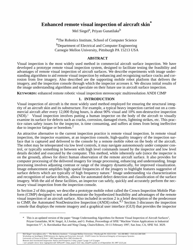
2. CIMPThe first aircraft-capable mobile robot developed at CMU was ANDI(the Automated NonDestructive Inspector of aging aircraft). ANDIsuccessful1y demonstrated mobility, manipulation and navigationalcapabilities on an aircraft surface. However, due to the ANDI projectemphasis on mobility and navigational issues, the delivery of highquality visual imagery useful for remote visual inspection was notaddressed at length. After the initial demonstrations of ANDI, thefirst author launched another research effort with the twin objectivesof designing a high quality remote imaging system that delivers use-ful inspection data and developing an inspection console consistingof a graphical user interface (GUI) and a library of image enhance-ment and understanding algorithms, through which an inspectorcould access, enhance and recognize surface defects from the liveimagery. [See the Acknowledgments section for additional historicaldetails.]
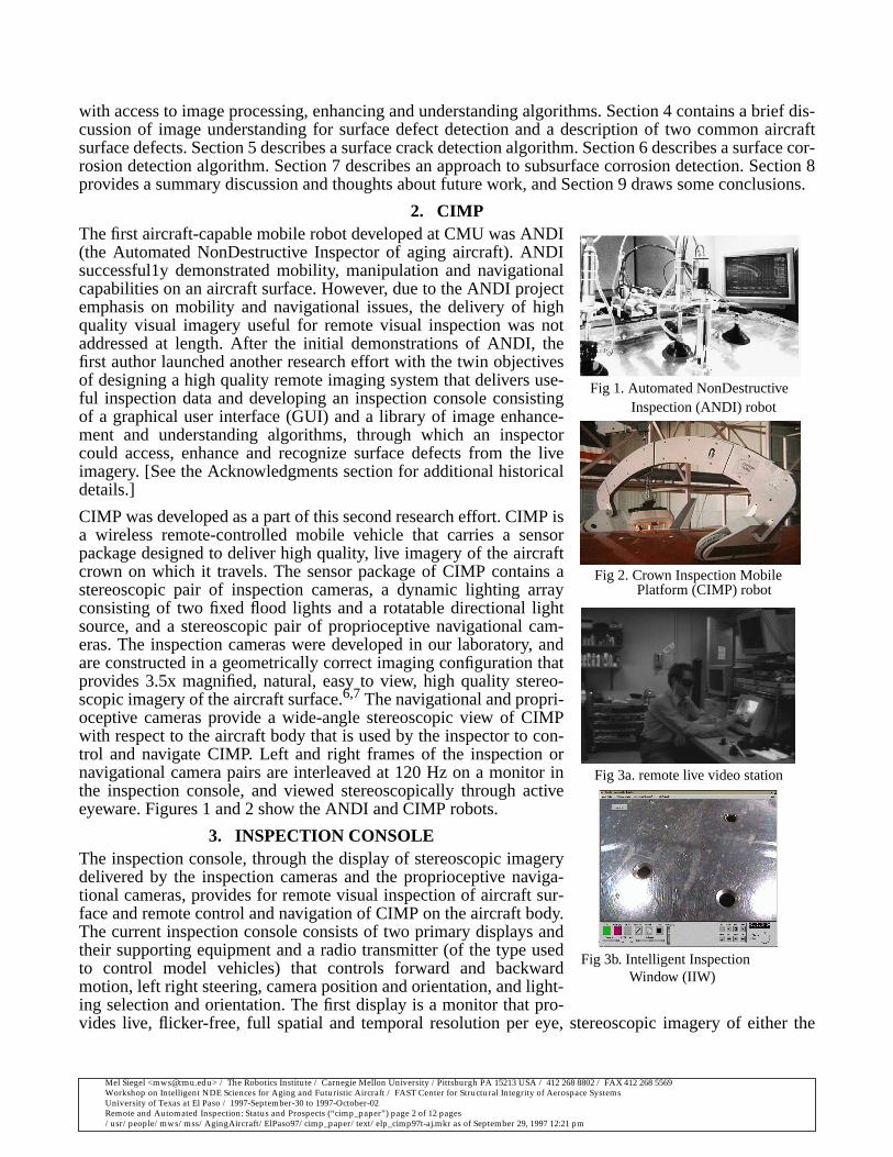
CIMP was developed as a part of this second research effort. CIMP isa wireless remote-controlled mobile vehicle that carries a sensorpackage designed to deliver high quality, live imagery of the aircraftcrown on which it travels. The sensor package of CIMP contains astereoscopic pair of inspection cameras, a dynamic lighting arrayconsisting of two fixed flood lights and a rotatable directional lightsource, and a stereoscopic pair of proprioceptive navigational cam-eras. The inspection cameras were developed in our laboratory, andare constructed in a geometrically correct imaging configuration thatprovides 3.5x magnified, natural, easy to view, high quality stereo-scopic imagery of the aircraft surface.6,7 The navigational and propri-oceptive cameras provide a wide-angle stereoscopic view of CIMPwith respect to the aircraft body that is used by the inspector to con-trol and navigate CIMP. Left and right frames of the inspection ornavigational camera pairs are interleaved at 120 Hz on a monitor inthe inspection console, and viewed stereoscopically through activeeyeware. Figures 1 and 2 show the ANDI and CIMP robots.
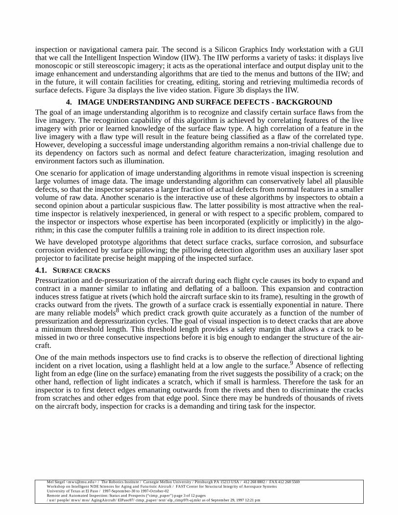
3. INSPECTION CONSOLEThe inspection console, through the display of stereoscopic imagerydelivered by the inspection cameras and the proprioceptive naviga-tional cameras, provides for remote visual inspection of aircraft sur-face and remote control and navigation of CIMP on the aircraft body.The current inspection console consists of two primary displays andtheir supporting equipment and a radio transmitter (of the type usedto control model vehicles) that controls forward and backwardmotion, left right steering, camera position and orientation, and light-ing selection and orientation. The first display is a monitor that pro-vides live, flicker-free, full spatial and temporal resolution per eye, stereoscopic imagery of either the
Fig 1. Automated NonDestructive
Fig 2. Crown Inspection Mobile
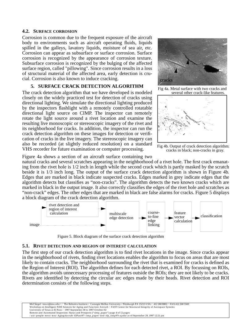
Fig 3b. Intelligent Inspection
Fig 3a. remote live video station
Inspection (ANDI) robot
Platform (CIMP) robot
Window (IIW)
Mel Siegel <[email protected]> / The Robotics Institute / Carnegie Mellon University /Pittsburgh PA 15213 USA / 412 268 8802 / FAX 412 268 5569Workshop on Intelligent NDE Sciences for Aging and Futuristic Aircraft / FAST Center for Structural Integrity of Aerospace SystemsUniversity of Texas at El Paso / 1997-September-30 to 1997-October-02Remote and Automated Inspection: Status and Prospects (“cimp_paper”) page 3 of 12 pages/usr/people/mws/mss/AgingAircraft/ElPaso97/cimp_paper/text/elp_cimp97t-aj.mkr as of September 29, 1997 12:21 pm
inspection or navigational camera pair. The second is a Silicon Graphics Indy workstation with a GUIthat we call the Intelligent Inspection Window (IIW). The IIW performs a variety of tasks: it displays livemonoscopic or still stereoscopic imagery; it acts as the operational interface and output display unit to theimage enhancement and understanding algorithms that are tied to the menus and buttons of the IIW; andin the future, it will contain facilities for creating, editing, storing and retrieving multimedia records ofsurface defects. Figure 3a displays the live video station. Figure 3b displays the IIW.
4. IMAGE UNDERSTANDING AND SURFACE DEFECTS - BACKGROUNDThe goal of an image understanding algorithm is to recognize and classify certain surface flaws from thelive imagery. The recognition capability of this algorithm is achieved by correlating features of the liveimagery with prior or learned knowledge of the surface flaw type. A high correlation of a feature in thelive imagery with a flaw type will result in the feature being classified as a flaw of the correlated type.However, developing a successful image understanding algorithm remains a non-trivial challenge due toits dependency on factors such as normal and defect feature characterization, imaging resolution andenvironment factors such as illumination.
One scenario for application of image understanding algorithms in remote visual inspection is screeninglarge volumes of image data. The image understanding algorithm can conservatively label all plausibledefects, so that the inspector separates a larger fraction of actual defects from normal features in a smallervolume of raw data. Another scenario is the interactive use of these algorithms by inspectors to obtain asecond opinion about a particular suspicious flaw. The latter possibility is most attractive when the real-time inspector is relatively inexperienced, in general or with respect to a specific problem, compared tothe inspector or inspectors whose expertise has been incorporated (explicitly or implicitly) in the algo-rithm; in this case the computer fulfills a training role in addition to its direct inspection role.
We have developed prototype algorithms that detect surface cracks, surface corrosion, and subsurfacecorrosion evidenced by surface pillowing; the pillowing detection algorithm uses an auxiliary laser spotprojector to facilitate precise height mapping of the inspected surface.
4.1. SURFACE CRACKS
Pressurization and de-pressurization of the aircraft during each flight cycle causes its body to expand andcontract in a manner similar to inflating and deflating of a balloon. This expansion and contractioninduces stress fatigue at rivets (which hold the aircraft surface skin to its frame), resulting in the growth ofcracks outward from the rivets. The growth of a surface crack is essentially exponential in nature. Thereare many reliable models8 which predict crack growth quite accurately as a function of the number ofpressurization and depressurization cycles. The goal of visual inspection is to detect cracks that are abovea minimum threshold length. This threshold length provides a safety margin that allows a crack to bemissed in two or three consecutive inspections before it is big enough to endanger the structure of the air-craft.
One of the main methods inspectors use to find cracks is to observe the reflection of directional lightingincident on a rivet location, using a flashlight held at a low angle to the surface.9 Absence of reflectinglight from an edge (line on the surface) emanating from the rivet suggests the possibility of a crack; on theother hand, reflection of light indicates a scratch, which if small is harmless. Therefore the task for aninspector is to first detect edges emanating outwards from the rivets and then to discriminate the cracksfrom scratches and other edges from that edge pool. Since there may be hundreds of thousands of rivetson the aircraft body, inspection for cracks is a demanding and tiring task for the inspector.
Mel Siegel <[email protected]> / The Robotics Institute / Carnegie Mellon University /Pittsburgh PA 15213 USA / 412 268 8802 / FAX 412 268 5569Workshop on Intelligent NDE Sciences for Aging and Futuristic Aircraft / FAST Center for Structural Integrity of Aerospace SystemsUniversity of Texas at El Paso / 1997-September-30 to 1997-October-02Remote and Automated Inspection: Status and Prospects (“cimp_paper”) page 4 of 12 pages/usr/people/mws/mss/AgingAircraft/ElPaso97/cimp_paper/text/elp_cimp97t-aj.mkr as of September 29, 1997 12:21 pm
4.2. SURFACE CORROSION
Corrosion is common due to the frequent exposure of the aircraftbody to environments such as aircraft operating fluids, liquidsspilled in the galleys, lavatory liquids, moisture of sea air, etc.Corrosion can appear as subsurface or surface corrosion. Surfacecorrosion is recognized by the appearance of corrosion texture.Subsurface corrosion is recognized by the bulging of the affectedsurface region, called "pillowing". Since corrosion results in a lossof structural material of the affected area, early detection is cru-cial. Corrosion is also known to induce cracking.
5. SURFACE CRACK DETECTION ALGORITHMThe crack detection algorithm that we have developed is modeledclosely on the widely practiced test for detection of cracks usingdirectional lighting. We simulate the directional lighting producedby the inspectors flashlight with a remotely controlled rotatabledirectional light source on CIMP. The inspector can remotelyrotate the light source around a rivet location and examine theresulting live monoscopic or stereoscopic imagery of the rivet andits neighborhood for cracks. In addition, the inspector can run thecrack detection algorithm on these images for detection or verifi-cation of cracks in the live imagery. The stereoscopic imagery canalso be recorded (at slightly reduced resolution) on a standardVHS recorder for future examination or computer processing.
Figure 4a shows a section of an aircraft surface containing twonatural cracks and several scratches appearing in the neighborhood of a rivet hole. The first crack emanat-ing from the rivet hole is 1/2 inch in length while the second crack which is partly masked by the scratchbeside it is 1/3 inch long. The output of the surface crack detection algorithm is shown in Figure 4b.Edges that are marked in black indicate suspected cracks. Edges marked in grey indicate edges that thealgorithm detects but classifies as “non-cracks”. The algorithm detects the two known cracks which aremarked in black in the output image. It also correctly classifies the edges of the rivet hole and scratches as“non-crack” edges. The other edges that are marked in black are false alarms for cracks. Figure 5 displaysa block diagram of the crack detection algorithm.
5.1. RIVET DETECTION AND REGION OF INTEREST CALCULATION
The first step of our crack detection algorithm is to find rivet locations in the image. Since cracks appearin the neighborhood of rivets, finding rivet locations enables the algorithm to focus on areas that are mostlikely to contain cracks. The neighborhood surrounding the rivet that is examined for cracks is defined asthe Region of Interest (ROI). The algorithm defines for each detected rivet, a ROI. By focussing on ROIs,the algorithm avoids unnecessary processing of features outside the ROIs; they are not likely to be cracks.Rivets are identified by detecting the circular arc edges made by their heads. Rivet detection and ROIdetermination consists of the following steps.
Fig 4b. Output of crack detection algorithm;
Fig 4a. Metal surface with two cracks and
cracks
several other crack-like features.
cracks in black; non-cracks in gray.
rivet detection and
coarse-to-fineedgelinking
featurevectorcalculation
classification
image
region of interestmultiscaleedge detection
Figure 5. Block diagram of the surface crack detection algorithm
calculation
Mel Siegel <[email protected]> / The Robotics Institute / Carnegie Mellon University /Pittsburgh PA 15213 USA / 412 268 8802 / FAX 412 268 5569Workshop on Intelligent NDE Sciences for Aging and Futuristic Aircraft / FAST Center for Structural Integrity of Aerospace SystemsUniversity of Texas at El Paso / 1997-September-30 to 1997-October-02Remote and Automated Inspection: Status and Prospects (“cimp_paper”) page 5 of 12 pages/usr/people/mws/mss/AgingAircraft/ElPaso97/cimp_paper/text/elp_cimp97t-aj.mkr as of September 29, 1997 12:21 pm
1. Smooth with a gaussian filter. Convolve with the x- and y- partial derivatives. Calculate thegradient magnitude image.2. Calculate the histogram of the gradient magnitude image. Define ahigh threshold above which lie a specified fraction of
the pixels. Mark the pixels above the high threshold asedge points. Link the edge points to createedges.3. Define alow threshold below which lie a specified fraction of the pixels. Grow edges with adjacent pixels below the low
threshold. Discard edges that contain fewer than 10 pixels.4. Fit a circular arc to each edge. Discard edges whose fit error is worse than a minimum value. The remaining edges are
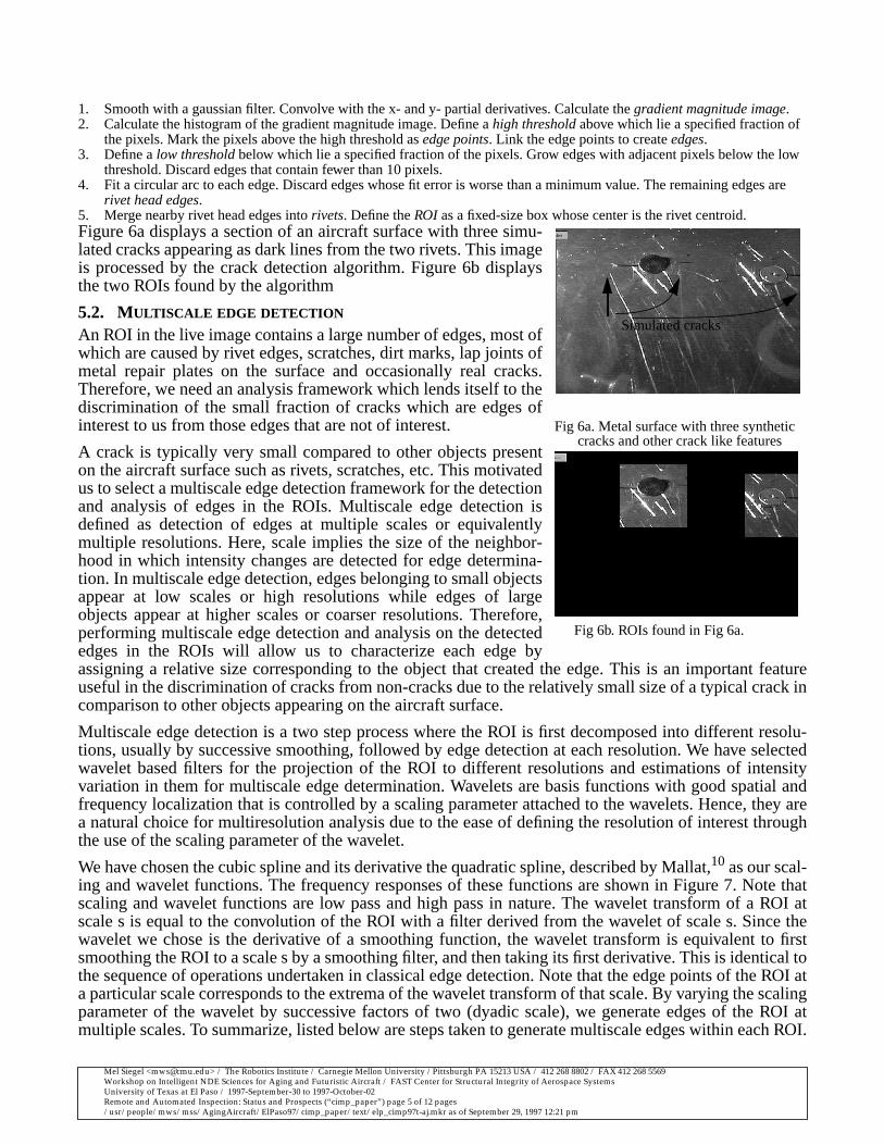
rivet head edges.5. Merge nearby rivet head edges intorivets. Define the ROI as a fixed-size box whose center is the rivet centroid.Figure 6a displays a section of an aircraft surface with three simu-lated cracks appearing as dark lines from the two rivets. This imageis processed by the crack detection algorithm. Figure 6b displaysthe two ROIs found by the algorithm
5.2. MULTISCALE EDGE DETECTION
An ROI in the live image contains a large number of edges, most ofwhich are caused by rivet edges, scratches, dirt marks, lap joints ofmetal repair plates on the surface and occasionally real cracks.Therefore, we need an analysis framework which lends itself to thediscrimination of the small fraction of cracks which are edges ofinterest to us from those edges that are not of interest.
A crack is typically very small compared to other objects presenton the aircraft surface such as rivets, scratches, etc. This motivatedus to select a multiscale edge detection framework for the detectionand analysis of edges in the ROIs. Multiscale edge detection isdefined as detection of edges at multiple scales or equivalentlymultiple resolutions. Here, scale implies the size of the neighbor-hood in which intensity changes are detected for edge determina-tion. In multiscale edge detection, edges belonging to small objectsappear at low scales or high resolutions while edges of largeobjects appear at higher scales or coarser resolutions. Therefore,performing multiscale edge detection and analysis on the detectededges in the ROIs will allow us to characterize each edge byassigning a relative size corresponding to the object that created the edge. This is an important featureuseful in the discrimination of cracks from non-cracks due to the relatively small size of a typical crack incomparison to other objects appearing on the aircraft surface.
Multiscale edge detection is a two step process where the ROI is first decomposed into different resolu-tions, usually by successive smoothing, followed by edge detection at each resolution. We have selectedwavelet based filters for the projection of the ROI to different resolutions and estimations of intensityvariation in them for multiscale edge determination. Wavelets are basis functions with good spatial andfrequency localization that is controlled by a scaling parameter attached to the wavelets. Hence, they area natural choice for multiresolution analysis due to the ease of defining the resolution of interest throughthe use of the scaling parameter of the wavelet.
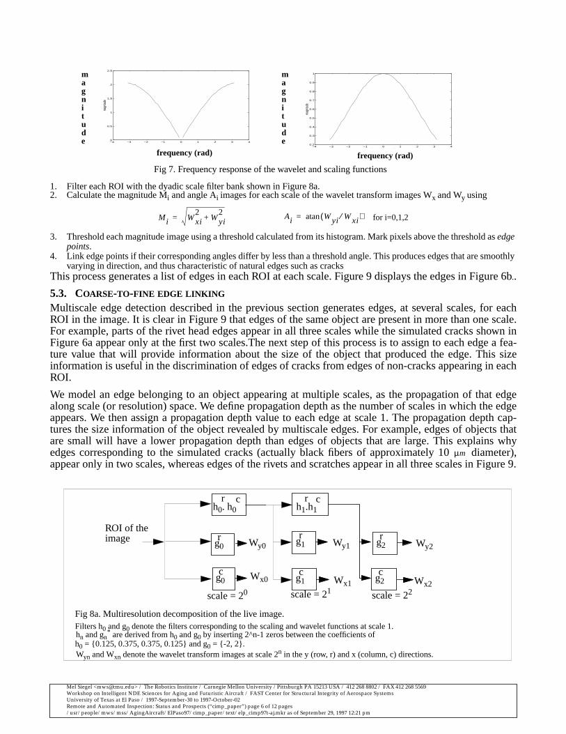
We have chosen the cubic spline and its derivative the quadratic spline, described by Mallat,10 as our scal-ing and wavelet functions. The frequency responses of these functions are shown in Figure 7. Note thatscaling and wavelet functions are low pass and high pass in nature. The wavelet transform of a ROI atscale s is equal to the convolution of the ROI with a filter derived from the wavelet of scale s. Since thewavelet we chose is the derivative of a smoothing function, the wavelet transform is equivalent to firstsmoothing the ROI to a scale s by a smoothing filter, and then taking its first derivative. This is identical tothe sequence of operations undertaken in classical edge detection. Note that the edge points of the ROI ata particular scale corresponds to the extrema of the wavelet transform of that scale. By varying the scalingparameter of the wavelet by successive factors of two (dyadic scale), we generate edges of the ROI atmultiple scales. To summarize, listed below are steps taken to generate multiscale edges within each ROI.
Fig 6b. ROIs found in Fig 6a.
Fig 6a. Metal surface with three syntheticcracks and other crack like features
Simulated cracks
Mel Siegel <[email protected]> / The Robotics Institute / Carnegie Mellon University /Pittsburgh PA 15213 USA / 412 268 8802 / FAX 412 268 5569Workshop on Intelligent NDE Sciences for Aging and Futuristic Aircraft / FAST Center for Structural Integrity of Aerospace SystemsUniversity of Texas at El Paso / 1997-September-30 to 1997-October-02Remote and Automated Inspection: Status and Prospects (“cimp_paper”) page 6 of 12 pages/usr/people/mws/mss/AgingAircraft/ElPaso97/cimp_paper/text/elp_cimp97t-aj.mkr as of September 29, 1997 12:21 pm
1. Filter each ROI with the dyadic scale filter bank shown in Figure 8a.2. Calculate the magnitude Mi and angle Ai images for each scale of the wavelet transform images Wx and Wy using
3. Threshold each magnitude image using a threshold calculated from its histogram. Mark pixels above the threshold asedgepoints.
4. Link edge points if their corresponding angles differ by less than a threshold angle. This produces edges that are smoothlyvarying in direction, and thus characteristic of natural edges such as cracks
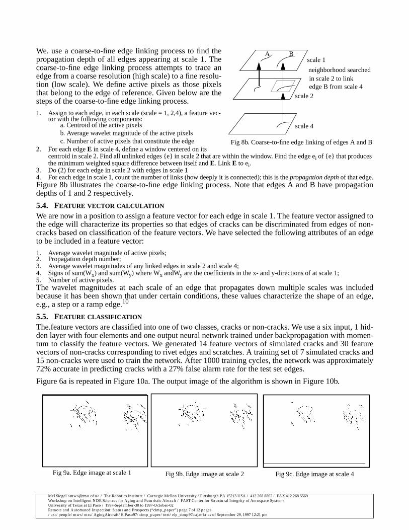
This process generates a list of edges in each ROI at each scale. Figure 9 displays the edges in Figure 6b..
5.3. COARSE-TO-FINE EDGE LINKING
Multiscale edge detection described in the previous section generates edges, at several scales, for eachROI in the image. It is clear in Figure 9 that edges of the same object are present in more than one scale.For example, parts of the rivet head edges appear in all three scales while the simulated cracks shown inFigure 6a appear only at the first two scales.The next step of this process is to assign to each edge a fea-ture value that will provide information about the size of the object that produced the edge. This sizeinformation is useful in the discrimination of edges of cracks from edges of non-cracks appearing in eachROI.
We model an edge belonging to an object appearing at multiple scales, as the propagation of that edgealong scale (or resolution) space. We define propagation depth as the number of scales in which the edgeappears. We then assign a propagation depth value to each edge at scale 1. The propagation depth cap-tures the size information of the object revealed by multiscale edges. For example, edges of objects thatare small will have a lower propagation depth than edges of objects that are large. This explains whyedges corresponding to the simulated cracks (actually black fibers of approximately 10 diameter),appear only in two scales, whereas edges of the rivets and scratches appear in all three scales in Figure 9.
Fig 7. Frequency response of the wavelet and scaling functions
−4 −3 −2 −1 0 1 2 3 40
0.5
1
1.5
2
2.5
frequency(rad)
magn
itude
−4 −3 −2 −1 0 1 2 3 40.2
0.3
0.4
0.5
0.6
0.7
0.8
0.9
1
frequency(rad)
magn
itude
magnitude
magnitude
frequency (rad) frequency (rad)
Mi Wxi2
Wyi2
+= Ai Wyi Wxi⁄( )atan= for i=0,1,2
g0r
g0c
g1r
g2r
g1c
g2c
Wx2
h0. h0r
h1.h1r
Wy2
ROI of theimage
c c
Wx1
Wy1
Wx0
Wy0
scale = 20 scale = 21 scale = 22
Fig 8a. Multiresolution decomposition of the live image.Filters h0 and g0 denote the filters corresponding to the scaling and wavelet functions at scale 1.hn and gn
* are derived from h0 and g0 by inserting 2^n-1 zeros between the coefficients of
Wyn and Wxn denote the wavelet transform images at scale 2n in the y (row, r) and x (column, c) directions.h0 = {0.125, 0.375, 0.375, 0.125} and g0 = {-2, 2}.
µm
Mel Siegel <[email protected]> / The Robotics Institute / Carnegie Mellon University /Pittsburgh PA 15213 USA / 412 268 8802 / FAX 412 268 5569Workshop on Intelligent NDE Sciences for Aging and Futuristic Aircraft / FAST Center for Structural Integrity of Aerospace SystemsUniversity of Texas at El Paso / 1997-September-30 to 1997-October-02Remote and Automated Inspection: Status and Prospects (“cimp_paper”) page 7 of 12 pages/usr/people/mws/mss/AgingAircraft/ElPaso97/cimp_paper/text/elp_cimp97t-aj.mkr as of September 29, 1997 12:21 pm
We. use a coarse-to-fine edge linking process to find thepropagation depth of all edges appearing at scale 1. Thecoarse-to-fine edge linking process attempts to trace anedge from a coarse resolution (high scale) to a fine resolu-tion (low scale). We define active pixels as those pixelsthat belong to the edge of reference. Given below are thesteps of the coarse-to-fine edge linking process.
1. Assign to each edge, in each scale (scale = 1, 2,4), a feature vec-tor with the following components:
a. Centroid of the active pixelsb. Average wavelet magnitude of the active pixelsc. Number of active pixels that constitute the edge
2. For each edgeE in scale 4, define a window centered on itscentroid in scale 2. Find all unlinked edges {e} in scale 2 that are within the window. Find the edge ei of {e} that producesthe minimum weighted square difference between itself andE. Link E to ei.
3. Do (2) for each edge in scale 2 with edges in scale 14. For each edge in scale 1, count the number of links (how deeply it is connected); this is thepropagation depth of that edge.Figure 8b illustrates the coarse-to-fine edge linking process. Note that edges A and B have propagationdepths of 1 and 2 respectively.
5.4. FEATURE VECTOR CALCULATION
We are now in a position to assign a feature vector for each edge in scale 1. The feature vector assigned tothe edge will characterize its properties so that edges of cracks can be discriminated from edges of non-cracks based on classification of the feature vectors. We have selected the following attributes of an edgeto be included in a feature vector:
1. Average wavelet magnitude of active pixels;2. Propagation depth number;3. Average wavelet magnitudes of any linked edges in scale 2 and scale 4;4. Signs of sum(Wx) and sum(Wy) where Wx andWy are the coefficients in the x- and y-directions of at scale 1;5. Number of active pixels.The wavelet magnitudes at each scale of an edge that propagates down multiple scales was includedbecause it has been shown that under certain conditions, these values characterize the shape of an edge,e.g., a step or a ramp edge.10
5.5. FEATURE CLASSIFICATION
The.feature vectors are classified into one of two classes, cracks or non-cracks. We use a six input, 1 hid-den layer with four elements and one output neural network trained under backpropagation with momen-tum to classify the feature vectors. We generated 14 feature vectors of simulated cracks and 30 featurevectors of non-cracks corresponding to rivet edges and scratches. A training set of 7 simulated cracks and15 non-cracks were used to train the network. After 1000 training cycles, the network was approximately72% accurate in predicting cracks with a 27% false alarm rate for the test set edges.
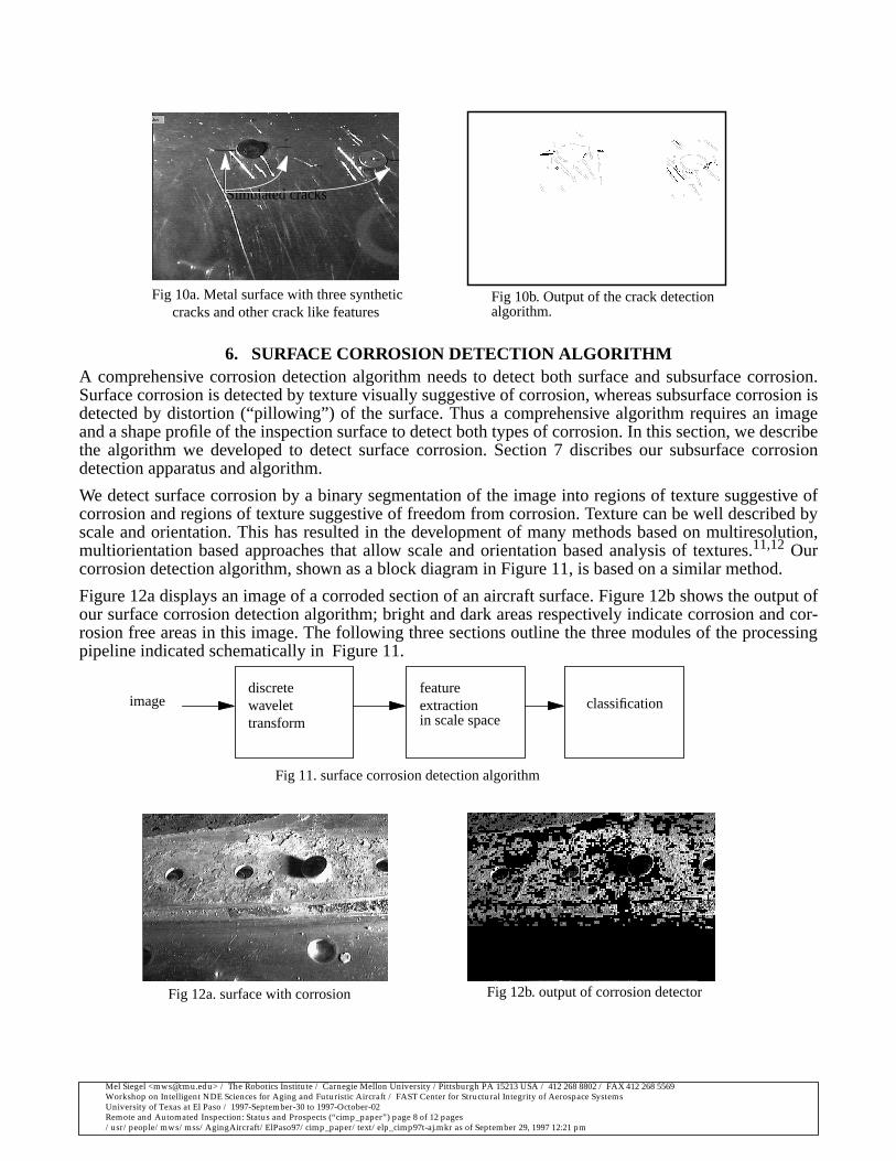
Figure 6a is repeated in Figure 10a. The output image of the algorithm is shown in Figure 10b.
scale 1
scale 4
A B
Fig 8b. Coarse-to-fine edge linking of edges A and B
neighborhood searched
scale 2
edge B from scale 4in scale 2 to link
Fig 9a. Edge image at scale 1 Fig 9b. Edge image at scale 2 Fig 9c. Edge image at scale 4
Mel Siegel <[email protected]> / The Robotics Institute / Carnegie Mellon University /Pittsburgh PA 15213 USA / 412 268 8802 / FAX 412 268 5569Workshop on Intelligent NDE Sciences for Aging and Futuristic Aircraft / FAST Center for Structural Integrity of Aerospace SystemsUniversity of Texas at El Paso / 1997-September-30 to 1997-October-02Remote and Automated Inspection: Status and Prospects (“cimp_paper”) page 8 of 12 pages/usr/people/mws/mss/AgingAircraft/ElPaso97/cimp_paper/text/elp_cimp97t-aj.mkr as of September 29, 1997 12:21 pm
6. SURFACE CORROSION DETECTION ALGORITHMA comprehensive corrosion detection algorithm needs to detect both surface and subsurface corrosion.Surface corrosion is detected by texture visually suggestive of corrosion, whereas subsurface corrosion isdetected by distortion (“pillowing”) of the surface. Thus a comprehensive algorithm requires an imageand a shape profile of the inspection surface to detect both types of corrosion. In this section, we describethe algorithm we developed to detect surface corrosion. Section 7 discribes our subsurface corrosiondetection apparatus and algorithm.
We detect surface corrosion by a binary segmentation of the image into regions of texture suggestive ofcorrosion and regions of texture suggestive of freedom from corrosion. Texture can be well described byscale and orientation. This has resulted in the development of many methods based on multiresolution,multiorientation based approaches that allow scale and orientation based analysis of textures.11,12 Ourcorrosion detection algorithm, shown as a block diagram in Figure 11, is based on a similar method.
Figure 12a displays an image of a corroded section of an aircraft surface. Figure 12b shows the output ofour surface corrosion detection algorithm; bright and dark areas respectively indicate corrosion and cor-rosion free areas in this image. The following three sections outline the three modules of the processingpipeline indicated schematically in Figure 11.
discretewavelettransform
featureextraction classificationimage
Fig 11. surface corrosion detection algorithm
in scale space
Fig 10a. Metal surface with three syntheticcracks and other crack like features
Fig 10b. Output of the crack detection
Simulated cracks
algorithm.
Fig 12a. surface with corrosion Fig 12b. output of corrosion detector
Mel Siegel <[email protected]> / The Robotics Institute / Carnegie Mellon University /Pittsburgh PA 15213 USA / 412 268 8802 / FAX 412 268 5569Workshop on Intelligent NDE Sciences for Aging and Futuristic Aircraft / FAST Center for Structural Integrity of Aerospace SystemsUniversity of Texas at El Paso / 1997-September-30 to 1997-October-02Remote and Automated Inspection: Status and Prospects (“cimp_paper”) page 9 of 12 pages/usr/people/mws/mss/AgingAircraft/ElPaso97/cimp_paper/text/elp_cimp97t-aj.mkr as of September 29, 1997 12:21 pm
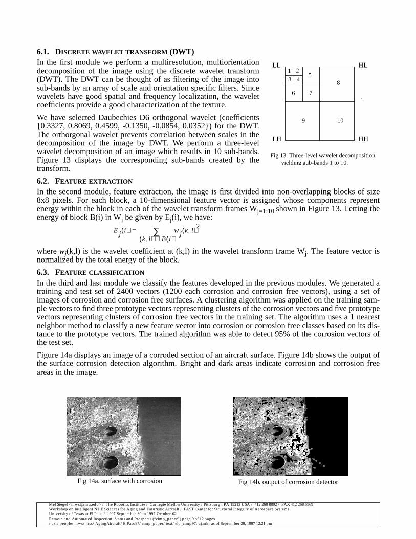
6.1. DISCRETE WAVELET TRANSFORM (DWT)In the first module we perform a multiresolution, multiorientationdecomposition of the image using the discrete wavelet transform(DWT). The DWT can be thought of as filtering of the image intosub-bands by an array of scale and orientation specific filters. Sincewavelets have good spatial and frequency localization, the waveletcoefficients provide a good characterization of the texture.
We have selected Daubechies D6 orthogonal wavelet (coefficients{0.3327, 0.8069, 0.4599, -0.1350, -0.0854, 0.0352}) for the DWT.The orthorgonal wavelet prevents correlation between scales in thedecomposition of the image by DWT. We perform a three-levelwavelet decomposition of an image which results in 10 sub-bands.Figure 13 displays the corresponding sub-bands created by thetransform.
6.2. FEATURE EXTRACTION
In the second module, feature extraction, the image is first divided into non-overlapping blocks of size8x8 pixels. For each block, a 10-dimensional feature vector is assigned whose components representenergy within the block in each of the wavelet transform frames Wj=1:10shown in Figure 13. Letting theenergy of block B(i) in Wj be given by Ej(i), we have:
where wj(k,l) is the wavelet coefficient at (k,l) in the wavelet transform frame Wj. The feature vector isnormalized by the total energy of the block.
6.3. FEATURE CLASSIFICATION
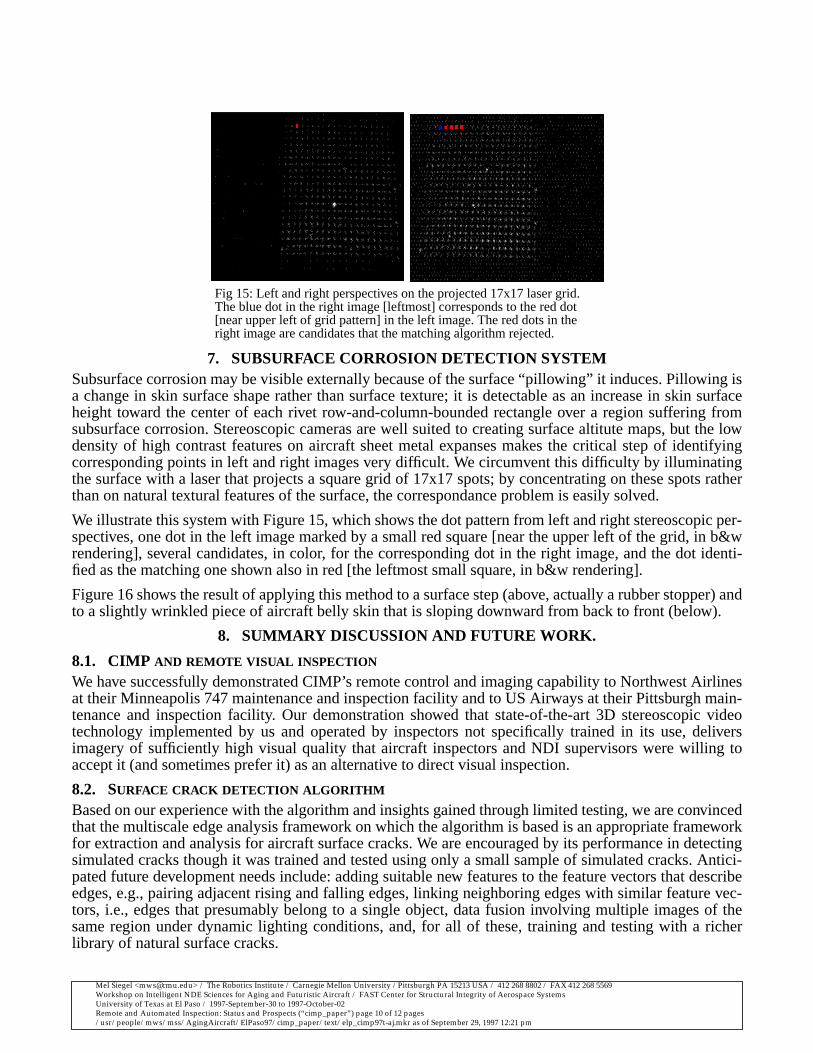
In the third and last module we classify the features developed in the previous modules. We generated atraining and test set of 2400 vectors (1200 each corrosion and corrosion free vectors), using a set ofimages of corrosion and corrosion free surfaces. A clustering algorithm was applied on the training sam-ple vectors to find three prototype vectors representing clusters of the corrosion vectors and five prototypevectors representing clusters of corrosion free vectors in the training set. The algorithm uses a 1 nearestneighbor method to classify a new feature vector into corrosion or corrosion free classes based on its dis-tance to the prototype vectors. The trained algorithm was able to detect 95% of the corrosion vectors ofthe test set.
Figure 14a displays an image of a corroded section of an aircraft surface. Figure 14b shows the output ofthe surface corrosion detection algorithm. Bright and dark areas indicate corrosion and corrosion freeareas in the image.
LL
LH
HL
HH
1 2
3 45
6 7
9
8
10
.
Fig 13. Three-level wavelet decompositionyielding aub-bands 1 to 10.
Ej i( ) wj k l,( )2
k l,( ) B i( )∈∑=
Fig 14a. surface with corrosion Fig 14b. output of corrosion detector
Mel Siegel <[email protected]> / The Robotics Institute / Carnegie Mellon University /Pittsburgh PA 15213 USA / 412 268 8802 / FAX 412 268 5569Workshop on Intelligent NDE Sciences for Aging and Futuristic Aircraft / FAST Center for Structural Integrity of Aerospace SystemsUniversity of Texas at El Paso / 1997-September-30 to 1997-October-02Remote and Automated Inspection: Status and Prospects (“cimp_paper”) page 10 of 12 pages/usr/people/mws/mss/AgingAircraft/ElPaso97/cimp_paper/text/elp_cimp97t-aj.mkr as of September 29, 1997 12:21 pm
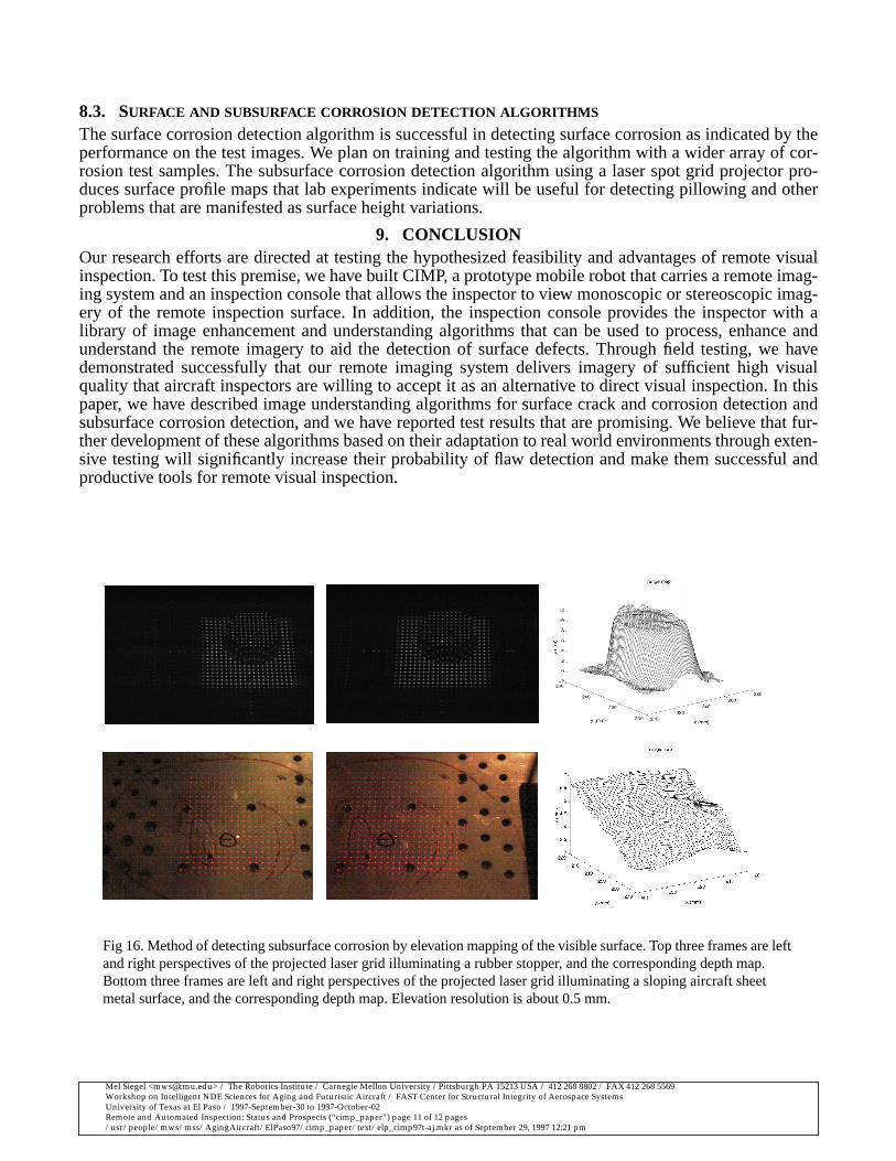
7. SUBSURFACE CORROSION DETECTION SYSTEMSubsurface corrosion may be visible externally because of the surface “pillowing” it induces. Pillowing isa change in skin surface shape rather than surface texture; it is detectable as an increase in skin surfaceheight toward the center of each rivet row-and-column-bounded rectangle over a region suffering fromsubsurface corrosion. Stereoscopic cameras are well suited to creating surface altitute maps, but the lowdensity of high contrast features on aircraft sheet metal expanses makes the critical step of identifyingcorresponding points in left and right images very difficult. We circumvent this difficulty by illuminatingthe surface with a laser that projects a square grid of 17x17 spots; by concentrating on these spots ratherthan on natural textural features of the surface, the correspondance problem is easily solved.
We illustrate this system with Figure 15, which shows the dot pattern from left and right stereoscopic per-spectives, one dot in the left image marked by a small red square [near the upper left of the grid, in b&wrendering], several candidates, in color, for the corresponding dot in the right image, and the dot identi-fied as the matching one shown also in red [the leftmost small square, in b&w rendering].
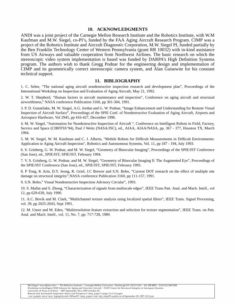
Figure 16 shows the result of applying this method to a surface step (above, actually a rubber stopper) andto a slightly wrinkled piece of aircraft belly skin that is sloping downward from back to front (below).
8. SUMMARY DISCUSSION AND FUTURE WORK.
8.1. CIMP AND REMOTE VISUAL INSPECTION
We have successfully demonstrated CIMP’s remote control and imaging capability to Northwest Airlinesat their Minneapolis 747 maintenance and inspection facility and to US Airways at their Pittsburgh main-tenance and inspection facility. Our demonstration showed that state-of-the-art 3D stereoscopic videotechnology implemented by us and operated by inspectors not specifically trained in its use, deliversimagery of sufficiently high visual quality that aircraft inspectors and NDI supervisors were willing toaccept it (and sometimes prefer it) as an alternative to direct visual inspection.
8.2. SURFACE CRACK DETECTION ALGORITHM
Based on our experience with the algorithm and insights gained through limited testing, we are convincedthat the multiscale edge analysis framework on which the algorithm is based is an appropriate frameworkfor extraction and analysis for aircraft surface cracks. We are encouraged by its performance in detectingsimulated cracks though it was trained and tested using only a small sample of simulated cracks. Antici-pated future development needs include: adding suitable new features to the feature vectors that describeedges, e.g., pairing adjacent rising and falling edges, linking neighboring edges with similar feature vec-tors, i.e., edges that presumably belong to a single object, data fusion involving multiple images of thesame region under dynamic lighting conditions, and, for all of these, training and testing with a richerlibrary of natural surface cracks.
Fig 15: Left and right perspectives on the projected 17x17 laser grid.The blue dot in the right image [leftmost] corresponds to the red dot[near upper left of grid pattern] in the left image. The red dots in theright image are candidates that the matching algorithm rejected.
Mel Siegel <[email protected]> / The Robotics Institute / Carnegie Mellon University /Pittsburgh PA 15213 USA / 412 268 8802 / FAX 412 268 5569Workshop on Intelligent NDE Sciences for Aging and Futuristic Aircraft / FAST Center for Structural Integrity of Aerospace SystemsUniversity of Texas at El Paso / 1997-September-30 to 1997-October-02Remote and Automated Inspection: Status and Prospects (“cimp_paper”) page 11 of 12 pages/usr/people/mws/mss/AgingAircraft/ElPaso97/cimp_paper/text/elp_cimp97t-aj.mkr as of September 29, 1997 12:21 pm
8.3. SURFACE AND SUBSURFACE CORROSION DETECTION ALGORITHMS
The surface corrosion detection algorithm is successful in detecting surface corrosion as indicated by theperformance on the test images. We plan on training and testing the algorithm with a wider array of cor-rosion test samples. The subsurface corrosion detection algorithm using a laser spot grid projector pro-duces surface profile maps that lab experiments indicate will be useful for detecting pillowing and otherproblems that are manifested as surface height variations.
9. CONCLUSIONOur research efforts are directed at testing the hypothesized feasibility and advantages of remote visualinspection. To test this premise, we have built CIMP, a prototype mobile robot that carries a remote imag-ing system and an inspection console that allows the inspector to view monoscopic or stereoscopic imag-ery of the remote inspection surface. In addition, the inspection console provides the inspector with alibrary of image enhancement and understanding algorithms that can be used to process, enhance andunderstand the remote imagery to aid the detection of surface defects. Through field testing, we havedemonstrated successfully that our remote imaging system delivers imagery of sufficient high visualquality that aircraft inspectors are willing to accept it as an alternative to direct visual inspection. In thispaper, we have described image understanding algorithms for surface crack and corrosion detection andsubsurface corrosion detection, and we have reported test results that are promising. We believe that fur-ther development of these algorithms based on their adaptation to real world environments through exten-sive testing will significantly increase their probability of flaw detection and make them successful andproductive tools for remote visual inspection.
Fig 16. Method of detecting subsurface corrosion by elevation mapping of the visible surface. Top three frames are leftand right perspectives of the projected laser grid illuminating a rubber stopper, and the corresponding depth map.Bottom three frames are left and right perspectives of the projected laser grid illuminating a sloping aircraft sheetmetal surface, and the corresponding depth map. Elevation resolution is about 0.5 mm.
Mel Siegel <[email protected]> / The Robotics Institute / Carnegie Mellon University /Pittsburgh PA 15213 USA / 412 268 8802 / FAX 412 268 5569Workshop on Intelligent NDE Sciences for Aging and Futuristic Aircraft / FAST Center for Structural Integrity of Aerospace SystemsUniversity of Texas at El Paso / 1997-September-30 to 1997-October-02Remote and Automated Inspection: Status and Prospects (“cimp_paper”) page 12 of 12 pages/usr/people/mws/mss/AgingAircraft/ElPaso97/cimp_paper/text/elp_cimp97t-aj.mkr as of September 29, 1997 12:21 pm
10. ACKNOWLEDGMENTSANDI was a joint project of the Carnegie Mellon Research Institute and the Robotics Institute, with W.MKaufman and M.W. Siegel, co-PI’s, funded by the FAA Aging Aircraft Research Program. CIMP was aproject of the Robotics Institute and Aircraft Diagnostic Corporation, M.W. Siegel PI, funded partially bythe Ben Franklin Technology Center of Western Pennsylvania (grant RR 10032) with in-kind assistancefrom US Airways and valuable cooperation from Northwest Airlines. The basic research on which thestereoscopic video system implementation is based was funded by DARPA’s High Definition Systemsprogram. The authors wish to thank Gregg Podnar for the engineering design and implementation ofCIMP and its geometrically correct stereoscopic camera system, and Alan Guisewite for his constanttechnical support.
11. BIBLIOGRAPHY1. C. Seher, “The national aging aircraft nondestructive inspection research and development plan”, Proceedings of theInternational Workshop on Inspection and Evaluation of Aging Aircraft, May 21, 1992.
2. W. T. Shepherd, “Human factors in aircraft maintenance and inspection”, Conference on aging aircraft and structuralairworthiness,” NASA conference Publication 3160, pp 301-304, 1991.
3. P. D. Gunatilake, M. W. Siegel, A.G. Jordan and G. W. Podnar, “Image Enhancement and Understanding for Remote VisualInspection of Aircraft Surface”, Proceedings of the SPIE Conf. of Nondestructive Evaluation of Aging Aircraft, Airports andAerospace Hardware, Vol 2945, pp 416-427, December 1996.
4. M. W. Siegel, “Automation for Nondestructive Inspection of Aircraft “, Conference on Intelligent Robots in Field, Factory,Service and Space (CIRFFSS’94), Paul J Weitz (NASA/JSC), ed., AIAA, AIAA/NASA, pp. 367 - 377, Houston TX, March1994.
5. M. W. Siegel, W. M. Kaufman and C. J. Alberts, "Mobile Robots for Difficult Measurements in Difficult Environments:Application to Aging Aircraft Inspection", Robotics and Autonomous Systems, Vol. 11, pp 187 - 194, July 1993.
6. S. Grinberg, G. W. Podnar, and M. W. Siegel, “Geometry of Binocular Imaging”, Proceedings of the SPIE/IST Conference(San Jose), ed., SPIE/IST, SPIE/IST, February 1994.
7. V. S. Grinberg, G. W. Podnar, and M. W. Siegel, “Geometry of Binocular Imaging ll: The Augmented Eye”, Proceedings ofthe SPIE/IST Conference (San Jose), ed., SPIE/IST, SPIE/IST, February 1995.
8. P Tong, K Arin, D.Y. Jeong, R. Grief, J.C Brewer and S.N. Bobo, “Current DOT research on the effect of multiple sitedamage on structural integrity”,NASA conference Publication 3160, pp 111-157, 1991.
9. S.N. Bobo,” Visual Nondestructive Inspection Advisory Circular”, 1993.
10. S. Mallat and S. Zhong, “Characterization of signals from multiscale edges”, IEEE Trans Patt. Anal. and Mach. Intell., vol12, pp 629-639, July 1990.
11. A.C. Bovik and M. Clark, “Multichannel texture analysis using localized spatial filters”, IEEE Trans. Signal Processing,vol. 39, pp 2025-2043, Sept 1991.
12. M. Unser and M. Eden, “Multiresolution feature extraction and selection for texture segmentation”, IEEE Trans. on Patt.Anal. and Mach. Intell., vol. 11, No. 7, pp: 717-728, 1989.