enhanced durability, quality control and monitoring of...
TRANSCRIPT

Fédération Internationale du Béton Proceedings of the 2nd International Congress June 5-8, 2006 – Naples, Italy ID 14-9 Session 14 – Reinforcing and prestressing materials and systems
Enhanced Durability, Quality Control and Monitoring of Electrically Isolated Tendons Della Vedova, M. Italferr S.p.A. (Gruppo F.S.), Italy Elsener, B. Instiitute for Buildng Materials, Swiss Federal Institute of Technology, Zurich, Switzerland and Department of Inorganic and Analytical Chemistry, University of Cagliari, Italy INTRODUCTION Post-tensioning tendons contribute decisively to the serviceablity, safety and durability of prestressed concrete (PC) bridges. In order to reach the goals of durability (optimum corrosion protection) and of monitoring requested by the Italian Railway [1] and the Swiss Federal Roads and Railway Authorities, the new system of electrically isolated tendons according to the Swiss Guideline [2] has been adopted. In Switzerland about 80 bridges of different length have been constructed since 1995 with thick-walled corru-gated plastic ducts and electrically isolated anchorages [3, 4]. Similar systems have been massively applied for the first time in Italy for the design and construction of several bridges and viaducts of the new high-speed lines [5, 6]. In Italy, traditional choice for railway bridges is the use of simply supported spans and about 90% of the viaducts of the new lines are realised with partial or total precasting of PC decks; this allowed to carry out test programmes on the construction site and extensive quality control during construction – a point that has been recognized to be more difficult on continuous span bridges as those usually constructed in Switzerland. The requirements, test methods and acceptance criteria in agreement with international regulations [7], have been applied. Electrically isolated tendons have been introduced as one possible solution to reach the highest protection level (PL3) in the framework of fib recommendations [8, 9]. Using electrically isolated tendons allows to check the electrical isolation of the tendons and the integrity of the plastic duct during and after construction [4, 10] and to monitor the corrosion protection of the tendons during service life with impedance measurements [10, 11]. This paper describes the state of the art with regard to enhanced durability, quality control and monitoring of post-tensioning tendons in prestressed concrete bridges with electrically isolated tendons (EIT). On the basis of the Italian and Swiss experience and critical evaluation of the results obtained so far solutions for practical problems and future developments are suggested. Keywords: post-tensioning, durability, anchorages, electrically isolated, impedance, monitoring TENDONS WITH METALLIC DUCTS Optimum corrosion protection of post-tensioning tendons has been a key-issue since the beginning of this technology. Indeed, long experience and generally a good “track record” with post-tensioning tendons using steel-stripe metallic duct with special corrugation are available from many different applications. However, some corrosion problems are documented that raise concerns about the durability of internal grouted post-tensioning tendons [12, 13]. The situation becomes even more severe as virtually no non-destructive technique is available to locate corroding tendons.

Proceedings of the 2nd Congress Session 14
June 5-8, 2006 – Naples, Italy Reinforcing and prestressing materials and systems
2
Corrosion Hazards The main reason for significant damage and corrosion of the prestressing steel is chloride containing water penetrating at weak points such as expansion joints, drainage systems etc. to the steel duct and then to the high-strength prestressing steel. From 143 structures analysed in Switzerland approximately half showed small to significant corrosion damage of the prestressing steel. In two out of twelve dismantled bridges the prestressing steel was found severely corroded [14, 15]. In prestressed railway bridges corrosion and / or hydrogen embrittlement due to stray currents may occur. It is thus important to have a low longitudinal electrical resistance of the rail and increase their resistance, i.e. insulation, with respect to the rebar network connected to the ground [16]. Fig. 1. Hazard scenarios for prestressing steel in a typical box girder bridge::Indication of potentially "weak points" where water (possibly contaminated with chlorides) can gain access to the tendons and cause corrosion. 1: Defective wearing course (e.g. cracks), 2: Missing or defective waterproofing membrane incl. edge areas, 3: Defective drainage intakes and pipes, 4: Wrongly placed outlets for the drainage of wearing course and waterproofing, 5: Leaking expansion joint, 6: Cracked and leaking construction or element joint, 7: Inserts (e.g. for electricity). P. Matt [15] Problems in Condition Assessment and Monitoring Condition assessment and monitoring of prestressed concrete structures is one of the major problems: in addition to possible durability problems today it is practically impossible to locate tendons that suffer corrosion. Visual inspection combined with non-destructive “state of the art” techniques such as half-cell potential mapping to locate corroding areas [17, 18] is not possible because the metallic ducts in electrical connection with the rebar network are shielding the high-strength prestressing steel. Other NDT methods [19] such as RIMT (reflectometric method known from high-energy and telecom cables) have been tested but shown to be ineffective to locate ruptures or loss in cross section of the steel strands in grouted tendons [20]. Some progress might be expected from the ongoing European Research Action COST 534 “New Materials and Systems for Prestressed Concrete Structures” [21] where intense research is ongoing on new NDT techniques such as Pulse-echo methods, impact-echo, ground penetrating radar and magnetic methods [22]. TENDONS WITH THICK-WALLED CORRUGATED PLASTIC DUCTS Plasic ducts have been used for many years in prestressing technology for applications as monostrands, ground anchors, stay cables and external tendons, mostly in the form of smooth pipes. Corrugated plastic
Proceedings of the 2nd Congress Session 14
June 5-8, 2006 – Naples, Italy Reinforcing and prestressing materials and systems
3
ducts have been used for ground anchors in the bond length. Between 1968 and 1974 about 300 000 m of thin walled corrugated black polyethylene ducts have been installed in Switzerland (the material at that time was cheaper than steel ducts). Some of these bridges have since been demolished and analysis of the polyethylene ducts, after up to 30 years in concrete, showed no deterioration.
Only since about 10 years have thick-walled plastic ducts for post-tensioning tendons become popular for use with curved tendons. The development in industry started about 15 years ago [4]. Thick-walled plastic ducts have been developed and introduced for the following reasons:
a) reduced friction losses during stressing of the tendon b) increased fretting fatigue resistance of the tendon [15, 23] c) improved corrosion protection, especially in the case of stray currents, which is a vital aspect for
railway bridges [2, 3] d) feasibility of electrical monitoring of the tendon during the whole service life [2, 3, 10, 11]
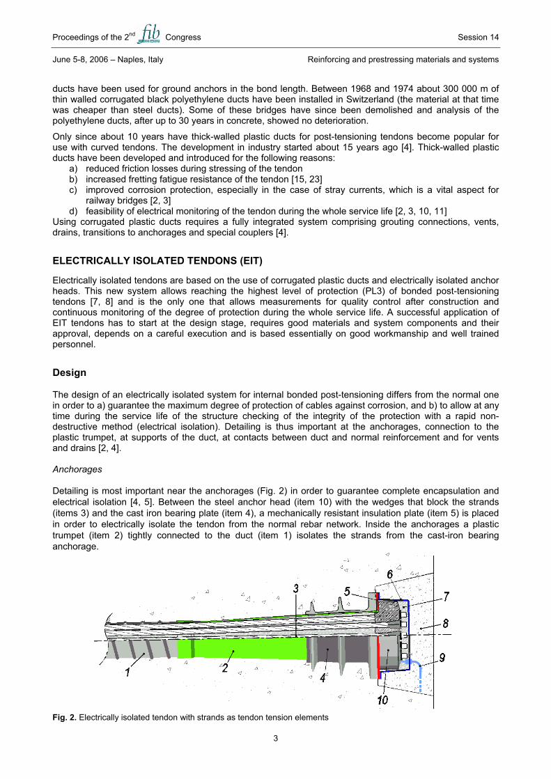
Using corrugated plastic ducts requires a fully integrated system comprising grouting connections, vents, drains, transitions to anchorages and special couplers [4]. ELECTRICALLY ISOLATED TENDONS (EIT) Electrically isolated tendons are based on the use of corrugated plastic ducts and electrically isolated anchor heads. This new system allows reaching the highest level of protection (PL3) of bonded post-tensioning tendons [7, 8] and is the only one that allows measurements for quality control after construction and continuous monitoring of the degree of protection during the whole service life. A successful application of EIT tendons has to start at the design stage, requires good materials and system components and their approval, depends on a careful execution and is based essentially on good workmanship and well trained personnel. Design The design of an electrically isolated system for internal bonded post-tensioning differs from the normal one in order to a) guarantee the maximum degree of protection of cables against corrosion, and b) to allow at any time during the service life of the structure checking of the integrity of the protection with a rapid non-destructive method (electrical isolation). Detailing is thus important at the anchorages, connection to the plastic trumpet, at supports of the duct, at contacts between duct and normal reinforcement and for vents and drains [2, 4]. Anchorages Detailing is most important near the anchorages (Fig. 2) in order to guarantee complete encapsulation and electrical isolation [4, 5]. Between the steel anchor head (item 10) with the wedges that block the strands (items 3) and the cast iron bearing plate (item 4), a mechanically resistant insulation plate (item 5) is placed in order to electrically isolate the tendon from the normal rebar network. Inside the anchorages a plastic trumpet (item 2) tightly connected to the duct (item 1) isolates the strands from the cast-iron bearing anchorage. Fig. 2. Electrically isolated tendon with strands as tendon tension elements

Proceedings of the 2nd Congress Session 14
June 5-8, 2006 – Naples, Italy Reinforcing and prestressing materials and systems
4
According to Swiss guideline [2], the anchor heads are protected by plastic caps (item 6) and fully grouted (item 7). Italian Railways asked for transparent caps in order to check visually the grouting execution of the caps at the end of the grouting and, if necessary, re-grout from additional inlet in the highest point of the caps, before covering them permanently. Actually, the Swissguideline leaves to the designers the choice to cover the anchorage caps with concrete or not. The Italian Railways choice was to ask to all designers for head anchorages completely surrounded by non-shrinking reinforced concrete (item 8), held in place by reinforcement, as a mean of further protection. An electrical terminal (item 9) is drawn out from the head anchorage for impedance measurements. Minimum cross-section area of the electric terminal shall be 6 mm2 for railway bridges with alternating current traction, 1 mm2 in other cases. The anchorage shall be in accessible position (even if covered with second step casting for further protection) and the box collecting all electric terminals of a single deck shall be in areas easily accessible for inspection and maintenance personnel. Reinforcement and concrete mix The normal reinforcement has to be designed around the anchorage, in the so-called "local zone", taking into account the effects of spalling and bursting due to prestressing force, and in order to guarantee proper concrete filling of formwork, with special attention behind the anchorages. For Italian railway PC decks, as minimum or no cracking is acceptable and expected to appear in prestressed concrete around the anchorages of post-tensioning tendons it was very important to focus on a good mix design for concrete (high early tensile and compressive concrete strengths) and a minimum amount of stressing necessary at early stage, for example, for precast deck transport to stocking area, in order to avoid larger cracking, which may cause loss of the measured electrical impedance, too. Concrete high temperature due to heat of hydration or steam curing, and large thickness of deck cross-section elements shall be carefully studied in presence of early stressing of tendons, as the ducts can be damaged. Ducts Ducts are usually made of high-density polyethylene or polypropylene: the fib Technical Report [8] specifies mechanical resistance and chemical requirements for the acceptance of a plastic duct. The mechanical properties of polymers depend on temperature: in cold periods, bending of the usually used material becomes very difficult, so low temperature versions of the ducts have been produced. This polymer however – when used at higher temperatures – may flow under pressure. Thus, at the points with the highest curvature (local pressure) and at any point where the duct is in contact with normal reinforcement sustaining half shells are recommended. These half shells today are made of a more resistant polymer and can be clamped on the ducts, they cover the bottom and the side of the duct. In the precast decks of the Italian high speed network, this was not necessary and the contact with large diameter smooth bars (at least 24 mm) used as supports, was tested for common curvatures of tendon and, through inspection of cores after testing (see "Qualification testing" paragraph in the following), it revealed to be efficient enough to protect the duct from local damage. Plastic linkage of the duct to the supports shall be adopted instead of steel one, as the latter may reduce impedance of the tendon. Duct curvature, support spacings, grout vents Great care must be put in respecting supports spacing and minimum duct curvatures, as suggested from the producers or from proper testing for a specific project. Plastic trumpet may need to be strengthened with an internal temporary steel trumpet during casting of concrete, because it may be unstable towards external pressure. Sealing and connections between duct segments, between duct, plastic trumpet and anchorage, or between duct and vents or drains have to be leak tight. Especially grout vents or inlets have to be carefully closed with plastic caps in order to avoid any electrolytic path between (internal) grout and concrete. System approval testing Any new prestressing system with plastic ducts has to pass a System Approval Testing [8]. In Switzerland two systems are approved so far. This approval is based on extensive laboratory tests, but no site tests are required. The Italian Railways have recently started to apply System Approval Testing to new post-tensioning system proposed by Italian construction companies, so far only one electrically isolated system

Proceedings of the 2nd Congress Session 14
June 5-8, 2006 – Naples, Italy Reinforcing and prestressing materials and systems
5
has been approved and diffusely used on site. The System Approval Testing – apart from chemical and mechanical tests on the post-tensioning system components – has to be performed on the prefabrication site before starting the construction, for every first application of a prestressing system with post-tensioning tendons, because personnel skills and experience, and available instruments in the viaduct site have decisive influence on system performance. The measurement of the electrical impedance to test the electrical isolation is only one of several tests which compose the System Approval Testing. These other tests should always be performed on site even when no-isolated systems with corrugated plastic ducts are adopted. Test beam As it is shown in the following, the good result in adopting these high standard ducts for enhanced durability of post-tensioning tendons should overpass good performance of site activities, as isolated systems deserve. As testing beam, for simply supported PC deck, the following simple rules were respected for the Italian railway simply supported spans (example in Fig. 3): the beam shall be half length of the real deck because duct profiles can be effectively represented; the width and height of the beam shall be as similar as possible to the real webs of deck cross-section, in the worst combination expected from design. This helps to evaluate the assembling of steel reinforcement (Fig. 4) around anchorage when a large amount is expected, because it can cause many interference with tendons components or casting. Fig. 3. Example of testing beam for Post-tensioning System Approval of simply supported PC deck, according to [7]. In case of continuous PC deck (e.g. the Marchiazza viaduct, as shown later), the testing beam length may vary depending on the characteristics of tendon profiles, as all relevant features (minimum radius of curvature, high points and low points of duct profiles, presence of couplers in case of segmental construction, fixed and stressable anchorages, duct connections, etc.) shall be represented in testing.
Fig. 4. Assembling of tendons in testing beam.
Fig. 5. Impedance measurements after stressing of tendons in testing beam
Fig. 6. Cores extraction from testing beam.
The choice of putting vents and drains shall follow the duct profile design and grouting procedure. In the System approval testing, every component and all sealings and connections between them are tested for leak tightness: with constant air pressure from the inside of the duct, and over a period of 5 minutes, the loss of initial 0.1 bar pressure shall not exceed 10%. The number of testing tendons to be introduced shall be representative of the real case too: it means at least one tendon per number of strands, straight or parabolic profiles etc. Redundancy has to be preferred because some tendon may fail during testing and not be useful for reaching final data for testing result. Besides, as it may be dangerous to cut cores behind the anchorage when strands

Proceedings of the 2nd Congress Session 14
June 5-8, 2006 – Naples, Italy Reinforcing and prestressing materials and systems
6
are stressed to the design value for stressing, before injection grouting de-stressing some tendon to a minimum value (e.g. 15% of design stress, tendon a in Fig. 3) may be necessary and redundancy may be useful, especially for measurements of the electrical isolation, because in this case short circuits present in the stressed situation may be not detected after de-stressing and grouting. The beam shown in Fig. 3 is very similar to the ones used for Piacenza viaduct (see the next chapter) and for Modena viaduct, along Milano-Bologna high-speed line [6]. For the latter, only corrugated plastic ducts for the no. 20 strands tendons, without isolated anchorages, were used. Of the representative tendons assembled in the testing beam, only one or two, with the smallest radius of curvature, may be de-stressed for core-extraction. For the continuos PC deck of the Modena system of viaduct (40-56-40 m, cast in situ in three segments) [6], the testing beam for the 40 mm bars post-tensioning system with HDPE ducts was designed taking into account the presence of couplers in the cross-sections between segments, and the local reinforcement connecting two cast in situ segments, was verified, so reproducing the real casting procedure. Stressing procedure Stressing has to take place in the worst condition expected from design: it means the minimum number of days from casting, with the lowest concrete compressive strength and comparable pressure and relative displacements of prestressing steel during stressing. Qualification testing on site may be a good chance to verify the design value of friction coefficient between duct and prestressing steel. Early measurements of electrical impedance, after stressing of tendons and before grouting (Fig. 5), are recommended in the Swiss guideline [2]. These measurements reveal short circuits or unexpected very low impedance between high-strength prestressing steel and the normal reinforcement. Reasons might be isolated anchorage with defects from production (for example, non perfect junction between insulation plate and plastic trumpet), damaged ducts due to unsufficient wear resistance (see damage in the duct after stressing in Fig. 7a), or too low stiffness or too long distance between supports (see out-of-roundness of duct cross-section in Fig. 7b), or cracking of concrete, due to very early stressing and poor concrete mix design, that made the whole system unstable, causing damages to the anchorage areas. The electrical impedance measurements provide information that cannot be obtained otherwise. Grouting Grouting operations have to be performed on testing beam cables as it is expected on real deck; for the post-tensioning tendons of PC railway bridge deck, injection with vacuum technique is always prescribed. The testing beam is a good chance to test the grouting procedure on full-scale tendons and the following core extraction helps to evaluate its level of confidence, as no void shall exceed 5% of duct diameter. Impedance measurements after grouting In tendons for which electrical insulation is measured after stressing, a drop of impedance is measured just after grouting due to filling of the whole length of the duct with an electrolyte. From that time on, impedance starts to increase with hydration and later slow drying of the grout (and partially also of the concrete). This process, as it is known from evolution of the electrical resistance of concrete [24] and grouts with time [25] may last for very long time (see chapter long term monitoring, fig. 18), similar to the strength development of concrete. This is the reason that the limiting value for sufficient electrical isolation refers to a fixed period of time after grouting (according to [2], 28 days). a b
Fig. 7. Examples of damages of duct (endoscopy). Fig. 8. Examples of cores for final inspection of duct and injection It must be here outlined that, in real cases, while waiting for this time interval is not relevant for

Proceedings of the 2nd Congress Session 14
June 5-8, 2006 – Naples, Italy Reinforcing and prestressing materials and systems
7
measurements on a single bridge, it may be important in prefabrication when construction speed for a large number of decks is elevated and the measurement activity is scattered over a long period of time and after time interval longer than time scheduling for launching, as we will see in the next chapter. Finally, cutting of cores (Fig. 6 and 8) helps to investigate the performance of the duct (wear resistance, cross-section deformation due to outer pressure of concrete, low stiffness over supports, etc.) and of the injection (complete filling of ducts cross-section, absence of air bubbles, absence of cracking, etc.), which lead to the final Approval of the Post-tensioning System. QUALITY CONTROL DURING CONSTRUCTION - RESULTS Once the System Approval Testing has led to the acceptance of the system, of the site facilities and the personnel skills, the construction of the bridge may start. To our opinion, a Quality Control System should always be implemented when high standards of technology are to be achieved in order to improve the overall quality of the infrastructure design and construction. It revealed to be the key operator for a strict check, led by Italferr (High Surveillance), on site activities of construction companies and it helped to diffuse a shared knowledge of high standard construction procedures and to quite easily transfer them from one site to another. A Quality Control Plan and correct reporting of data assures that all materials and components for the specific project maintain, during production, the same properties as guaranteed with the qualification testing. Actually, the Quality Control System works in an integrated system of detailed design documents, construction procedures with all allowable tolerances on each activity measure, and a detailed scheduling of construction phases. At the end of the process, for people operating on site, Quality Control Plans help to take note and keep memory of site activities and the application of tolerances that are shared between the controller body and the construction company, giving an easy answer whether the results are acceptable compared to what was expected or not. If the results of measurements were not acceptable, a feedback from site operations may lead to an upgrading of construction schedules, procedures and even of design assumptions. Electrically isolated tendons – a new dimension in quality control In case of PC decks with electrically isolated tendons, whether they are pre-cast or not, the Quality Control enters in a new dimension: the impedance measurements allow checking the electrical isolation of the tendons from the normal rebar network. These measurements are a very sensitive control of the tightness of the duct and the anchor head, influenced not only by the post-tensioning system but by design and execution of the structure. The Swiss guideline [2] adopted both in Switzerland and Italy specifies limiting values of the specific electrical resistance of the tendon that have to be reached by 90% of the tendons.
Fig. 9. Principle of measuring the electri-cal impedance of a tendon with the LCR
meter
Fig. 10. Electrical equivalent circuit for an electrically isolated tendon with small defects [3]
Measuring the impedance of the duct The measurements of the electrical isolation between the strand and the rebars require a sound electrical connection (item 9 in fig. 2) to each individual tendon (mostly mounted to one of the end anchorages) and
0.1110100SµA2]-600-500-400-300-200Potential[mV(SCE)]Temperatur[C]:-1001020304050 individual segments of ductwith defect with defectno defect no defect
Rd
Ch
Rd
Ch
Ch
Ch
Rh
Rh
Rh
Rh
Grouted plastic duct with steel strands
Rebars
LCR meter

Proceedings of the 2nd Congress Session 14
June 5-8, 2006 – Naples, Italy Reinforcing and prestressing materials and systems
8
another connection to the rebars. All the connection wires (area 1 mm2 apart from the case of AC railway bridges where it is 6 mm2) are concentrated in a box easily accessible. Monitoring of the electrically isolated tendons is performed with AC impedance measurements at a frequency of 1 kHz with portable LCR meters. The instrument measures the impedance Z that includes (over the whole tendon length) the grout in the duct, the duct (with couplers, vents, pores and defects) and the concrete surrounding the duct (Fig. 9). Grout and concrete are (at 1 kHz) pure resistances, the intact polymer duct is a pure capacitance and “defects” are represented by several ohmic resistances in parallel (fig. 10). The instrument calculates and displays the ohmic resistance R, the capacitance C and the loss factor D. The capacitance C is constant for a specific tendon length, diameter and material of the duct; it increases proportionally to the length of the tendon. The capacitance C can thus be used as a first control value to check the tendon integrity [2 – 4, 9 – 11]. The ohmic resistance R for a given tendon decreases with its length L. For a good electrical isolation the specific value ρ = R*L (Ωm) should be as high as possible, limiting values based on laboratory studies and field experience are given in [2]. The specific resistance ρ increases with time due to hydration and drying out of grout and concrete. The measurements of R, C and D allow to determine the degree of electrical isolation (and thus of the tightness of the duct on its whole length) at any time after grouting. This can be used both for quality control and for long-term monitoring of the corrosion protection of post-tensioned tendons. Results from pre-cast segmental viaducts – Piacenza In the Italian high speed network the Piacenza viaduct (Fig. 11 and 12) on the Milano-Bologna line is an example for full-span pre-casting of 151simply supported pre-cast prestressed concrete decks composed by a monolithic box girder with two cells, spanning 33.1 m and weighting about 1000 tons. The design of the elements and of the viaduct has been reported previously [5, 6]. Data have been collected from the first 71 decks of the Piacenza viaduct (fig. 12) , each contiaining 9 cables with 12 wires, duct ø 76 mm (in the lower slab) and 15 cables with 19 wires, duct ø 100 mm (in the webs).
Fig. 11. Piacenza viaduct anchorages and transparent cap [5].
Fig. 12. Piacenza viaduct full span precast deck in stocking area.
The values of the capacitance C (table 1) allow a first control on the execution quality. The values of the capacitance are Gaussian distributed and show a very small standard deviation, indicating the good reproducibility. The mean value is higher for ducts with higher diameter, the specific capacitance (per meter length) is well below the control values specified in [2]. This indicates that the duct wall thicknesses are higher than specified.
Tab. 1. Mean values and standard deviation of the capacitance values of the tendons tested
Piacenza viaduct Marchiazza viaduct [2] Type C mean
[nF] Std dev
[nF] Length
[m] C spec [nF/m]
C mean [nF]
Std dev [nF]
Length [m]
C spec [nF/m]
C lim [nF/m]
Ø 76 mm 70.3 2.3 32.1 2.2 166.5 2.0 72 2.3 3.05 Ø 100 mm 73.5 2.2 32.1 2.3 - 3.35

Proceedings of the 2nd Congress Session 14
June 5-8, 2006 – Naples, Italy Reinforcing and prestressing materials and systems
9
The statistical analysis of the measured resistance R on more then 1000 tendons is more complicated because the values – despite the constant length of the tendons – do not show a gaussian distribution. The analysis is thus performed with the cumulative probability plot (fig. 13, 14). For the tendons with ø 100 mm from the segments of the Piacenza viaduct (fig. 13), less then 1% of all values are below 10 Ohm, thus cables with a short circuit (electrical contact between tendon and normal rebars). The limiting value of the specific resistance ρ = 300 kΩ*m according to [2] results in a limiting resistance value R = 9 kΩ for the tendon with length 32.1 m. As can be seen from fig. 15 the limiting value is not reached by about 9% of the tendons. For the tendons with duct ø 76 mm the limiting value was not reached by 20%. The cumulative probability plot shows further that there is no specific tendon position that makes more difficulties then others. In addition, it can be noted that for each tendon position about 5% of all segments were produced with perfect isolation (reaching the theoretical value of a completely tight plastic duct). The broad distribution of resistance values measured shows that there is a strong influence of the human factor, as written procedures, approved material and components, deck formwork, reinforcement and pre-stressing were always the same. Following the measured resistance values over time, a rapid increase of impedance values was observed for the first decks, then the percentage of failure remained more or less constant.
Fig. 13. Cumulative probability distribution of the resistance
R, measured for 19 strands E.I. cables in 71 Piacenza viaduct decks.
Fig. 14. Cumulative probability distribution of the specific resistance ρ, measured for 19 strands E.I. cables in 33
Marchiazza viaduct decks. Results from continuous slab bridges – Marchiazza viaduct In the Italian high speed network the Marchiazza viaduct (Fig. 15 and 16) is an example of a three spans (22-28-22 m) continuous slab bridge along the Torino-Milano railway line [6], with heigth of the slab 2.70 m. It is cast and prestressed in situ in formworks scaffolding from the ground; it has no.33 19-strands tendons with the length of 72 m and high points of duct profiles over central piers. The measured capacitance values C (table 1) show a very narrow Gaussian distribution (standard deviation only 2 nF). This indicates a very good reproducibility in the construction process as material and geometry of the duct are the same. The specific resistance values (cumulative probability plot fig. 14) are for about 75% of all tendons above the limiting value of 300 kΩm [2]. In contrast to the data from the Piacenza viaduct, no tendon reached the theoretical maximum value. As the prestressing company and the details of the isolation of the anchor head were the same as in the Piacenza viaduct, one would expect similar results as in the Piacenza viaduct. However, the construction company was different, thus all the experience and the personnel training was different.

Proceedings of the 2nd Congress Session 14
June 5-8, 2006 – Naples, Italy Reinforcing and prestressing materials and systems
10
Fig. 15. Marchiazza viaduct, Torino-Milano high-speed line. Fig. 16. Marchiazza ducts assembling.
Results from continuous slab bridges – bridges and flyovers in Switzerland Experience from continuous slab bridges from Switzerland is only partially available and published [3, 4, 11]. Since the construction of the first flyovers (pilot-projects) [3, 4] about 100 structures (both railway and highway bridges or flyovers) were built with electrically isolated tendons. Main reasons to choose EIT technology was the possibility to monitor the tendons during service life, improved corrosion protection, risk of stray currents and reduced fretting fatigue. Overall, only about 60 - 70% of all tendons fulfil the criteria of the guideline [2]. This might have several reasons:
1) Every structure is “unique” in its design, not all engineers are familiar with the special design requirements when using plastic ducts and electrically isolated anchorages.
2) The system approval test is performed on the components in the laboratory and not on several tendons on site
3) The construction company often has no specific experience with EIT systems and the personnel working on site frequently changes, thus instruction becomes very difficult
4) Quality control until today is concentrated mainly at the prestressing company – defects often are detected too late.
5) A systematic quality control system as practiced by the Italian Railways (Italferr) is lacking. Further considerations It may be remarked from the reported experience that the care in assembling the cages of reinforcement and the components of tendons, the attention in respecting the casting procedure, good curing of concrete, early prestressing and injection grouting may be as decisive for good results of the impedance measurements as careful detailing of isolated anchorages or plastic ducts. For pre-cast elements there is enough time to take advantage of the results from the first elements to improve the overall quality during the follow-up of production; at the same time, the repetition of the same activities for a large number of times and over a long period of time may cause some drop of attention, especially when many elements have to be casted, stressed and launched in short time (for the Piacenza viaduct, two complete monolithic decks had to be built in a target cycle of only one week). Sometimes, at the end of production, when the pre-casting plant is going to be dismantled, a slight drop of attention and of impedance may be observed. For cast in situ PC decks or small production of precast elements, there is usually not enough time to take advantage of direct experience on site, apart from that gained with the System Approval Testing. On a long cast in-situ railway bridge (Raron bridge, Switzerland) an improvement (learning curve) was observed during construction. Generally these kinds of application need, since the beginning, the best-trained personnel available and with specific previous experience. LONG TERM MONITORING One of the main concerns regarding internal bonded post-tensioned tendons is the inability to inspect the tendons visually and the absence of established non-destructive techniques to monitor corrosion of the steel strands. Using electrically isolated tendons with plastic ducts, the evolution of the resistance values over time can be used to control the ntegrity of the corrosion protection system. As an example the flyover “Pré du Mariage” (fig. 17) is presented. It is a relatively simple, short box girder

Proceedings of the 2nd Congress Session 14
June 5-8, 2006 – Naples, Italy Reinforcing and prestressing materials and systems
11
structure with only one column in the middle. Six electrically isolated tendons of ø 76 mm and length 49.3 m were used. At “Pré du Mariage” electrical impedance measurements have been performed at frequent intervals since the time of grouting. The evolution of the electrical resistance with time is shown in figure 18. As can be noted, the values for the six individual tendons show a certain scatter, but the overall trend is an increase of the electrical resistance with time. In the log R vs log t plot a straight line with slope 0.5 is found.
Fig. 17. Flyover “Pré du Mariage” near Avenches (highway A2 Switzerland)
Fig. 18. Evolution of the electrical resistance of the six tendons of the flyover “Pré du Mariage” with time
This is equivalent to the normal square root law indicating that the increase in resistance is very rapid at the beginning and slows down after some month. This trend is expected to continue, with small variations due to temperature, for all tendons and for the entire future service life of the structure. Deviations from the expected trend, a decrease in the resistance of one or several tendons, allows detection of the ingress of (chloride containing) water at a very early stage: if water reaches a defect in the duct, the concrete and the grout near the defect get wet and the electrical resistance of this specific tendon will drop. Thus the measurement of the electrical impedance of the electrically isolated tendons at the normal inspection intervals represents a simple but very effective early warning system to detect a corrosion risk situation long before corrosion actually starts. Enough time is available to locate the defect with magnetic measurements [26], to judge the corrosion risk and to plan rehabilitation. An additional advantage is that no sensors (with unknown reliability and long term stability) are needed: the steel strands to be controlled represent the sensors for remote monitoring, thus EIT tendons can be considered a “smart structure”. CONCLUSIONS Measurements of the electrical impedance on electrically isolated tendons have shown to be an efficient way for quality control of the tendons. Monitoring over time allows the idenification of the penetration of (chloride containing) water at defects in the ducts. Thus for the first time, a simple, cost-effective early warning system for post-tensioning tendons is available.
Main factors for success of a new electrically isolated system are high quality material and components, a detailed design focused on the aspects remarked in the paper, proper testing, the personnel skills and experience in execution and the respect of well established construction procedure.
Italian experience with Piacenza viaduct taught us that a good co-operation between surveillance body, engineers, tendons firm and the construction companies is important: without any previous experience with electrically isolated tendons, it took only few months to get an efficient system. Apart from all necessary good detailing of tendons and high standard construction procedures, this was strongly due to the common aim, which these different players were sharing.
ACKNOWLEDGEMENTS The authors acknowledge financial support of the European Research Project COST 534 “New Materials and Systems for Prestressed Concrete” and of the Swiss Federal Highway Agency.

Proceedings of the 2nd Congress Session 14
June 5-8, 2006 – Naples, Italy Reinforcing and prestressing materials and systems
12
REFERENCES 1. Italian standard for railway bridges: Istruzione F.S. n. I/SC/PS-OM/2298 del 2.6.1995 “Sovraccarichi
per il calcolo dei ponti ferroviari - Istruzioni per la progettazione, l’esecuzione e il collaudo”, Final review 1997.
2. “Measures to ensure the durability of post-tensioning tendons in bridges”, guideline of the Swiss Federal Roads Authority and Swiss Federal Railways, edition 2001. PDF-Download under www.astra.admin.ch
3. B. Elsener, L. Toller, C.H. Vôute, H. Böhni, Ueberprüfen des Korosionsschutzes von Spanngliedern mit Kunststoffhüllrohren, Report Nr. 564 (VSS) Zürich (2002)
4. J. Ayats, A. Gnägi, B. Elsener, Electrical Isolation as Enhanced Protection for Post-tensioning Tendons in Concrete Structures, fib Congress 2002, October 13-19, Osaka, Japan
5. Prevedini, C., Averardi Ripari, F., Della Vedova, M., “Il Viadotto Piacenza per la Linea ad Alta Velocità Milano-Bologna, una soluzione costruttiva tecnologicamente avanzata con un sistema di precompressione innovativo”, Giornate Aicap, 27/29 Maggio 2004, Verona
6. R. Bonasso, G. Traini, M. Della Vedova, High speed railway prestressed concrete bridges, Proc. Of the 2nd International fib congress, 5/8 July 2006, Naples
7. Corrugated plastic ducts for internal bonded post-tensioning, Technical Report Bulletin 7, Fédération internationale du béton (fib), 2000
8. fib Draft Recommandation TG 5.4 (March 2004) to be published as fib bulletin Nr. 9. B. Elsener (ed.), Procedings of the second international workshop on durability of post-tensioning
tendons, Zurich 10. – 13. October 2004. To be published as fib bulletin (2006) 10. M. Della Vedova, B Elsener, L. Evangelista, Corrosion protection and monitoring of electrically isolated
post-tensioning tendons, Schriftenreihe der Technischen Universität Wien, Proc. Third European Conference on Structural Control, 3ESCC, Vienna July 2004, ed. R. Fleisch, H. Irschik and M. Krommer, Vol. II pp. S5-47 – S5-51
11. B. Elsener, Long-term monitoring of electrically isolated post-tensioning tendons, fib Journal “Structural Control” 6 (2005) 101 – 106
12. Durability of post-tensioning tendons, fib Bulletin, 2001, No. 15, pp. 1 – 88 (Chapter Inventory and Condition).
13. Durable post-tensioned concrete bridges. Concrete Society Technical Report 47, The Concrete Society, Crowthorne, UK, Second edition 2002
14. F. Hunkeler, H. Ungricht, P. Matt, Corrosion damage on prestressing steels in tendons and prestressed soil and rock anchors, VSS Report No. 534, Vereinigung Schweizer Strassenfachleute (VSS) Zurich, 1998 (in German)
15. P. Matt, Performance of post-tensioning bridges in Switzerland, IABSE Congress 2000, Luzern, Switzerland, 2000.
16. L. Bertolini, B. Elsener, P. Pedeferri, R. Polder, Corrosion of Steel in Concrete – Prevention, Diagnosis, Repair, WILEY VCH (2004) chapter 9
17. B. Elsener et al., Half Cell Potenital Measurements – Potential mapping on reinforced concrete structures, RILEM Recommendation TC154 EMC, Materials and Structures, 36 (2003) 461 - 471
18. B. Elsener, Construction and Building Materials 15 (2001) 133 - 139 19. Matt P., Non-destructive evaluation and monitoring of post-tensioning tendons, fib bulletin 15, Durability
of post-tensioning tendons (2001) pp. 103 - 108 20. B. Elsener, H. Böhni, R. Bräunlich, A. Markees, Zerstörungsfreie Spannkabelprüfung mit Reflekto-
metrischer Impulsmessung, Bericht Nr. 528, Verein Schweiz Strassenfachleute VSS, Zürich (1997) 21. www.cost534.com 22. E. Proverbio, Non-destructive evaluation of steel tendons in post-tensioned concrete structures,
Materials Engineering 12 (2001) 7 – 32 23. H.R. Ganz, Plastic ducts for enhanced performance of post-tensioning tendons, FIP Notes 1997/2, The
Institution of Structural Engineers, London, (1997) pp. 15 – 18 24. D. Bürchler, B. Elsener and H. Böhni, Electrical resistivity and dielectric porperties of hardened cement
paste and mortar. ASM Fall meeting, Boston (27.-30. 11. 1995), Electrically based Microstructural Characterization, ed. R.A. Gerhardt, S.R. Taylor and E.J. Garboczi, Mat. Res. Soc. Symp. Proc. Vol. 411 (1996) 407
25. V. Nicollier, Monitoring of electrically isolated tendons, Diploma thesis Institute for Building Materials ETHZ (2005), in German
26. M. Büchler, Research Report VSS No. 586 (2005)